Measuring Apparatus Counterbalance
BROWN; Christian ; et al.
U.S. patent application number 16/495364 was filed with the patent office on 2020-05-14 for measuring apparatus counterbalance. This patent application is currently assigned to RENISHAW PLC. The applicant listed for this patent is RENISHAW PLC. Invention is credited to Christian BROWN, Hugo George DERRICK.
| Application Number | 20200149859 16/495364 |
| Document ID | / |
| Family ID | 58606203 |
| Filed Date | 2020-05-14 |


| United States Patent Application | 20200149859 |
| Kind Code | A1 |
| BROWN; Christian ; et al. | May 14, 2020 |
MEASURING APPARATUS COUNTERBALANCE
Abstract
A positioning apparatus including a quill on which a probe apparatus can be mounted, at least one motor for positioning the quill in a substantially vertical dimension, and a pneumatic counterbalance mechanism for the quill. The positioning apparatus is configured, based on at least one factor relating to the quill, to automatically effect a change in the pneumatic counterbalance mechanism's pressure so as to thereby adapt the counterbalance force on the quill provided by the pneumatic counterbalance mechanism.
| Inventors: | BROWN; Christian; (Wotton-under-Edge, GB) ; DERRICK; Hugo George; (Stroud, GB) | ||||||||||
| Applicant: |
|
||||||||||
|---|---|---|---|---|---|---|---|---|---|---|---|
| Assignee: | RENISHAW PLC Wotton-under-Edge, Gloucestershire GB |
||||||||||
| Family ID: | 58606203 | ||||||||||
| Appl. No.: | 16/495364 | ||||||||||
| Filed: | April 17, 2018 | ||||||||||
| PCT Filed: | April 17, 2018 | ||||||||||
| PCT NO: | PCT/GB2018/050994 | ||||||||||
| 371 Date: | September 18, 2019 |
| Current U.S. Class: | 1/1 |
| Current CPC Class: | G01B 5/012 20130101; G01B 5/008 20130101; G01B 5/0016 20130101; G01B 21/047 20130101; G01B 21/045 20130101 |
| International Class: | G01B 5/00 20060101 G01B005/00; G01B 5/012 20060101 G01B005/012; G01B 21/04 20060101 G01B021/04 |
Foreign Application Data
| Date | Code | Application Number |
|---|---|---|
| Apr 19, 2017 | EP | 17275051.5 |
Claims
1. A positioning apparatus comprising a quill on which a probe apparatus can be mounted, at least one motor for positioning the quill in a substantially vertical dimension, and a pneumatic counterbalance mechanism for the quill, in which the positioning apparatus is configured, based on at least one factor relating to the quill, to automatically effect a change in the pneumatic counterbalance mechanism's pressure so as to thereby adapt the counterbalance force on the quill provided by the pneumatic counterbalance mechanism.
2. A positioning apparatus as claimed in claim 1, in which the at least one motor comprises a direct drive motor, optionally a linear motor.
3. A positioning apparatus as claimed in claim 1, in which the at least one factor relates to the actual or expected vertical position of the quill.
4. A positioning apparatus as claimed in claim 1, further comprising one or more position encoders for measuring the vertical position of the quill, and in which the at least one factor comprises the output from at least one of said one or more position encoders.
5. A positioning apparatus as claimed in claim 1, in which the at least one factor relates to the actual or expected power requirement of the at least one motor.
6. A positioning apparatus as claimed in claim 1, in which the at least one factor relates to the actual or expected direction of travel of the quill.
7. A positioning apparatus as claimed in claim 6, configured to adapt the pneumatic counterbalance mechanism's pressure so as to assist the motor in moving the quill in the direction of travel.
8. A positioning apparatus as claimed in claim 1, in which the at least one factor relates to at least one module loaded or to be loaded on the quill.
9. A positioning apparatus as claimed in claim 8, in which the at least one factor relates to the weight of the at least one module.
10. A positioning apparatus as claimed in claim 8, in which the at least one factor is determined by assessing the effect the module loaded on the quill has on the coordinate positioning apparatus.
11. A positioning apparatus as claimed in claim 1, comprising a pressure regulator which is configured to maintain the pneumatic counterbalance mechanism's pressure at a set pressure, and in which the apparatus is configured to alter the set pressure based on the at least one factor.
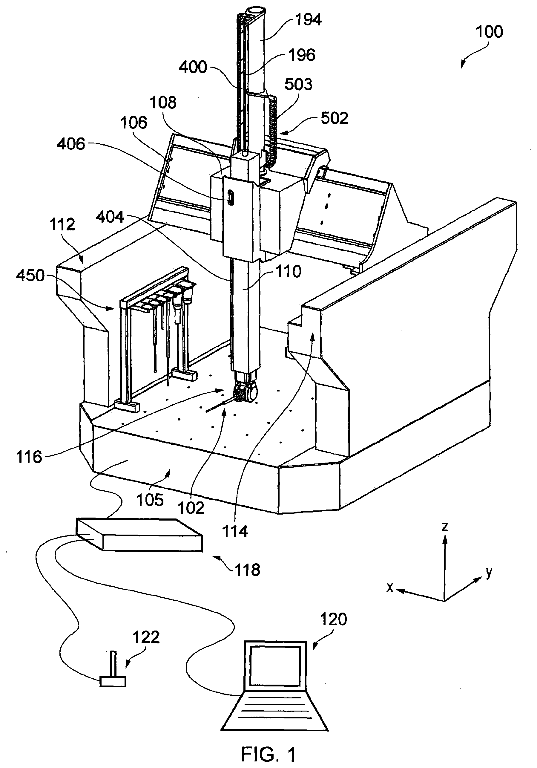
12. A positioning apparatus as claimed in claim 1, in which the change in the pneumatic counterbalance mechanism's pressure is determined from a look-up table and/or function.
13. A positioning apparatus as claimed in claim 1, configured to automatically adapt the pneumatic counterbalance mechanism's pressure in response to an expected or measured change in the load on the quill.
14. A positioning apparatus as claimed in claim 1, in which the positioning apparatus comprises a Cartesian coordinate positioning apparatus.
15. A method of operating a positioning apparatus comprising a quill on which a probe apparatus can be mounted, at least one motor for moving the quill in a substantially vertical dimension, a pneumatic counterbalance mechanism for the quill, the method comprising automatically effecting a change in the pneumatic counterbalance mechanism's pressure so as to thereby adapt the counterbalance force on the quill provided by the pneumatic counterbalance mechanism, based on the quill's status.
16. A positioning apparatus, comprising: first and second members relatively moveable in a substantially vertical degree of freedom, in which an energy conduit is connected to at least one of the first and second members, wherein the load, in the degree of freedom of the first and second members, imparted by the energy conduit on at least one of the members it is connected to varies dependent on the relative position of the first and second members, and further comprising a pneumatic counterbalance configured to apply a load, in the degree of freedom of the first and second members, that varies, dependent on the relative position of the first and second members, inversely to the load applied by the energy conduit, such variation in load being achieved by varying the air pressure of the pneumatic counterbalance.
Description
[0001] This invention relates to a counterbalance for a positioning apparatus such as a coordinate measuring machine (CMM). In particular, the invention relates to a counterbalance for the quill of a Cartesian coordinate positioning apparatus,
[0002] Positioning apparatus can comprise one or more moveable members for positioning a tool and/or an object relative to each other. For example, a CMM traditionally comprises a plurality of moveable members, e.g. linearly moveable members arranged in series. Generally, positioning apparatus are configured to facilitate relative motion of a tool and/or object in at least two or three mutually orthogonal dimensions, e.g. X, Y and Z. Such positioning apparatus are commonly known as "Cartesian" positioning apparatus (or Cartesian CMM). Typical Cartesian coordinate positioning apparatus include Bridge, Portal, Cantilever, Horizontal Arm, and Gantry type machines.
[0003] Often, the tool is mounted on a vertically moveable member. This member is typically known as a "quill", but is also known as z-ram or z-axis. As will be understood, the tool could be mounted directly to the quill, or via another member, such as an articulated head member which enables the tool to be repositioned about one or more rotational axes.
[0004] In order to reduce the requirements on the motor, it is known to provide a counterbalance mechanism for counterbalancing the weight of the quill. An example of such a counterbalance mechanism for a quill is described in U.S. Pat. Nos. 3,818,596 and 6,397,485. It is also known to provide pneumatic counterbalance mechanisms, for example as described in DE4408912, US875594, U.S. Pat. Nos. 4,389,781, 4,507,868, 4,799,316, 4,213,244 and 4,207,680.
[0005] The present invention relates to an improved pneumatic counterbalance system for a quill of a positioning apparatus.
[0006] According to a first aspect of the invention there is provided a positioning apparatus comprising a quill on which a probe apparatus can be mounted, at least one motor for positioning the quill in a substantially vertical dimension, and a pneumatic counterbalance mechanism for the quill. The positioning apparatus can be configured, on the basis of at least one factor relating to the quill, to automatically effect (i.e. cause/bring about) a change in the pneumatic counterbalance mechanism's pressure. Such a change in the pneumatic counterbalance mechanism's pressure could adapt the counterbalance force on the quill provided by the pneumatic counterbalance mechanism. Accordingly, the positioning apparatus of the present invention can be configured to automatically effect/cause a change in the pneumatic counterbalance mechanism's pressure so as to at least partially (and optionally substantially) compensate for any assumed/expected or actual/measured change quill circumstance, e.g. to compensate for any assumed/expected or actual/measured change in load on the quill, in the substantially vertical dimension.
[0007] The present invention has been found to improve the performance of the positioning apparatus, for example its metrological performance. In particular, automatically changing the pneumatic counterbalance mechanism's pressure can reduce variation in the power required of the motor for positioning (e.g. moving and/or holding) the quill in the substantially vertical dimension. This in turn can reduce variations in heat produced by the motor. Reducing variations in heat produced by the motor can improve the metrological performance of the positioning apparatus. As explained in more detail, the present invention can be used to automatically change the pneumatic counterbalance mechanism's pressure depending on a variety quill factors/circumstances, including, for example, the (expected/assumed or actual/measured) vertical position of the quill, the (expected/assumed or actual/measured) direction of travel of the quill in a vertical dimension, what module(s), such as a probe, is or are to be mounted on the quill, the quill's motor power requirement (e.g. expected/assumed or actual/measured), and/or a particular operation performed by the apparatus/quill (e.g. such as loading or unloading a probe to/from the quill). In summary, the present invention can be used to automatically change the pneumatic counterbalance mechanism's pressure depending on the expected/assumed or actual/measured load, current or future, on the quill.
[0008] As will be understood, the counterbalance mechanism can be configured to partially counterbalance the load on the quill. Optionally, the counterbalance mechanism can be configured to substantially counterbalance the load on the quill. Either way, preferably the apparatus is configured, based on the at least one factor relating to the quill, to automatically cause a change in the pneumatic pressure of the pneumatic counterbalance mechanism, so as to adapt the counterbalance force on the quill, e.g. so as to reduce (and for example to avoid substantial) variations in the power required by the motor (i.e. reduce compared to what would otherwise be required if the change in pressure is not made). For instance, the invention can be used to reduce (and for example to avoid substantial) variations in the power required by the motor to hold the quill at different vertical positions, and/or to reduce (and for example to avoid substantial) variations in the power required by the motor to hold the quill at any given vertical position but with different modules loaded thereon, and/or to reduce (and for example to avoid substantial) variations in the power required by the motor depending on whether the quill is being moved either up or down.
[0009] As will be understood, the pneumatic counterbalance mechanism could comprise a cylinder and associated piston. Pressurised gas (e.g. gas above atmospheric pressure) could act on the cylinder and/or piston in order to provide a counterbalance force. The cylinder and/or piston may or may not be provided by the quill (e.g. inside or on the quill). For example, the cylinder and/or piston may be provided separately and attached to the quill, e.g. via wire/cord, pulling system, rod or other linking mechanism/means.
[0010] The positioning apparatus could comprise a counterbalance controller. This could comprise a system. The positioning apparatus (for example the counterbalance controller) could for example be configured to monitor one or more aspects/factors/inputs regarding the quill. The positioning apparatus (for example the counterbalance controller) could be configured to automatically control the counterbalancing effect of the counterbalance mechanism on the quill based on said monitoring. The positioning apparatus (for example the counterbalance controller) could be configured to continuously monitor the aspect(s)/factor(s)/input(s) regarding the quill and control/adapt the pneumatic pressure of the pneumatic counterbalance mechanism instantaneously. Optionally the positioning apparatus (for example the counterbalance controller) is configured to control/adapt the pneumatic pressure of the pneumatic counterbalance mechanism at intervals, e.g. regular intervals and/or at predetermined instances (such as when changing a probe). The positioning apparatus (for example the counterbalance controller) could be configured to receive at least one input regarding the quill (e.g. its status) and be configured to automatically effect/cause said change in the pneumatic counterbalance mechanism's pressure. The positioning apparatus (for example the counterbalance controller) could be configured to monitor (or respond to) the input continuously or could be configured to monitor (or respond to) the input at intervals (e.g. at regular intervals and/or at predetermined instances).
[0011] The positioning apparatus could comprise at least one energy conduit connected/mounted to the quill. As will be understood, an energy conduit can comprise one or more wires and/or pipes (e.g. fluid lines), for supplying power, carrying signals and/or fluid to and/or from various parts of the apparatus. An energy conduit can comprise at least one wire and/or at least one pipe. An energy conduit can comprise at least one group/bunch of wires and/or pipes. The energy conduit could comprise a mix of wires and pipes. The wires and/or pipes could be tied together, e.g. using cable ties. An energy conduit can comprise a support track, e.g. for supporting at least one cable and/or at least one pipe. The support track could comprise an articulated support track. For example, an articulated support track could comprise a chained arrangement of pivotally connected links. Optionally, the support track could comprise a band of material which bends with the relative movement (e.g. comprise a continuous ribbon-like band of material).
[0012] The load/force in the substantially vertical dimension imparted by an energy conduit on the quill could vary dependent on the vertical position of the quill (e.g. due to the proportion of the energy conduit's mass which the quill carries varying with position). Accordingly, the positioning apparatus could be configured to effect/cause a change in the pressure of the pneumatic counterbalance mechanism so as to compensate for said change in load imparted by the at least one energy conduit on the quill.
[0013] As will be understood, the pneumatic counterbalance mechanism could be considered to be an active compensatory member e.g. which compensates at least partially for any (e.g. varying) load on the quill (e.g. in the vertical dimension). For example, the pneumatic counterbalance mechanism/compensatory member could be part of a system (e.g. which can comprise the counterbalance controller) which monitors at least one (e.g. system) input/variable (e.g. load applied to the quill, position of the quill, and/or direction of motion of the quill) and adapt/change the load the pneumatic counterbalance mechanism/compensatory member applies so as to at least partially counteract any change in load applied (e.g. applied by an energy conduit). Accordingly, the pneumatic counterbalance mechanism/compensatory member could be part of a servo system, which controls the pneumatic counterbalance mechanism/compensatory member in response to an input. The positioning apparatus could be configured to (e.g. dynamically) vary the counterbalance force provided by the pneumatic counterbalance mechanism in response to at least one input/variable (e.g. load applied on the quill, and/or position of the quill). For example, the positioning apparatus could be configured to (e.g. dynamically) vary the air pressure of the pneumatic counterbalance mechanism in response to at least one factor/input/variable (e.g. load applied on the quill, and/or position of the quill).
[0014] The positioning apparatus (e.g. the counterbalance controller) can be configured to determine how to change the pneumatic counterbalance mechanism's pressure.
[0015] As will be understood, the positioning apparatus (e.g. the counterbalance controller) can comprise a device. As will be understood, the device could comprise circuitry, such as any or a combination of a processor, microprocessor, central processing unit, field-programmable gate array (fpga), and memory/storage, which is configured, based on at least one factor relating to the quill, to automatically effect a change in the pneumatic counterbalance mechanism's pressure. As will be understood, the invention could be implemented at least partly in software, for example running on such a device. That is, the positioning apparatus could comprise software which is configured, based on at least one factor relating to the quill, to automatically effect a change in the pneumatic counterbalance mechanism's pressure.
[0016] The positioning apparatus could comprise a controller for controlling the position of the quill. For example, the controller could be configured to execute a computer program and control the at least one motor in accordance with the computer program (e.g. by controlling a motor power amplifier, optionally in conjuction with quill position information, such as from a position encoder). Optionally, the controller is configured to automatically effect said change in the pneumatic counterbalance mechanism's pressure based on said at least one factor relating to the quill. For example, optionally, the controller comprises the aforementioned counterbalance controller.
[0017] The at least one motor could comprise a direct drive motor. Optionally the at least one motor comprises a linear motor. It has been found that the invention is particularly useful in overcoming metrology problems caused by heating of direct drive motors, and in particular linear motors. Optionally, the linear motor comprises an elongate linear stator and an armature. Optionally, the armature is mounted to the quill.
[0018] The at least one factor (e.g. aspect/input) can relate to the actual or expected vertical position of the quill. The expected position could be a position that the quill is expected or assumed to be at. Such an expected position could, for example, be derived from a computer program (such as an inspection program or a calibration program, for example) being used to control the positioning apparatus (e.g. so as to inspect an artefact or calibrate the positioning apparatus or a sensor mounted thereon). The actual position of the quill could be the position the quill is measured to be at. For example, the actual position could be determined from one or more sensors, e.g. mounted on the positioning apparatus. For example, a sensor could comprise an accelerometer or a position encoder, e.g. a linear position encoder. For example, the actual vertical position of the quill could be determined via a readhead mounted on one part of the positioning apparatus reading a scale mounted on another part of the positioning apparatus. Optionally, the scale is mounted on the quill. Accordingly, the apparatus could comprise one or more position encoders for measuring the vertical position of the quill. The at least one factor (e.g. aspect/input) can comprise the output from at least one of said one or more position encoders.
[0019] As will be understood, the positioning apparatus (e.g. the counterbalance controller) may or may not determine how to change the pneumatic counterbalance mechanism's pressure based on the current/present (e.g. instantaneous) position of the quill (which could be expected/assumed or actual/measured). For example, it could do so based on an expected (e.g. near) future position of the quill. For example, it could predict or determine the future position of the quill and based thereon change the counterbalance mechanism's pressure (e.g. slightly) in advance.
[0020] The at least one factor (e.g. aspect/input) can relate to the actual/measured or expected/assumed power requirement of the at least one motor. Such an expected power requirement could, for example, be derived from a computer program (such as an inspection program or a calibration program, for example) being used to control the positioning apparatus (e.g. so as to inspect an artefact or calibrate the positioning apparatus or a sensor mounted thereon). The actual power requirement could be determined, for example from a motor power amplifier used to power the motor. The at least one factor (e.g. aspect/input) can relate to the current/present (e.g. instantaneous) power requirement of the at least one motor. As will be understood, the positioning apparatus (e.g. the counterbalance controller) may or may not determine how to change the pneumatic counterbalance mechanism's pressure based on the current/present (e.g. instantaneous) power requirement of the at least one motor. For example, it could do so based on an expected (e.g. near) future power requirement of the at least one motor. For example, it could predict or determine the future power requirement of the at least one motor and based thereon change the counterbalance mechanism's pressure (e.g. slightly) in advance.
[0021] The at least one factor (e.g. aspect/input) can relate to the actual or expected direction of travel of the quill. Such an expected direction of travel could, for example, be derived from a computer program (such as an inspection program or a calibration program, for example) being used to control the positioning apparatus (e.g. so as to inspect an artefact or calibrate the positioning apparatus or a sensor mounted thereon). The actual direction of travel could be determined, for example, from one or more sensors, such as an accelerometer or position encoder, e.g. a linear position encoder. As will be understood, the positioning apparatus (e.g. the counterbalance controller) may or may not determine how to change the pneumatic counterbalance mechanism's pressure based on the current/present (e.g. instantaneous) direction of travel. For example, it could do so based on an expected (e.g. near) future direction of travel. For example, it could predict or determine the direction of travel and based thereon change the counterbalance mechanism's pressure (e.g. slightly) in advance.
[0022] Accordingly, in accordance with the above embodiments, the positioning apparatus could be configured to change the pneumatic counterbalance mechanism's pressure based on a (expected) future quill load/status. For example, it could predict or determine the future quill load/status and based thereon cause a change the counterbalance mechanism's pressure (e.g. slightly) in advance.
[0023] The positioning apparatus (e.g. the counterbalance controller) could be configured to adapt the pneumatic counterbalance mechanism's pressure so as to assist the motor in moving the quill in the direction of travel.
[0024] The at least one factor (e.g. aspect/input) can relate to at least one module, such as a probe, loaded or to be loaded on the quill. The at least one factor (e.g. aspect/input) can relate to the weight (or mass) of the at least one module loaded or to be loaded on the quill. The at least one factor (e.g. aspect/input) relating to the at least one module could, for example, be a predetermined factor (e.g. aspect/input) associated with the module loaded or to be loaded on the quill. For example, the at least one factor (e.g. aspect/input) could be a module identifier. In such a case, the unique module identifier could be used to look up the weight of the module for example. Optionally, the predetermined factor (e.g. aspect/input) associated with the module loaded or to be loaded on the quill could comprise a value (e.g. the weight of the probe) or setting which can be used to determine how to control the pneumatic counterbalance mechanism's pressure.
[0025] Optionally, the at least one factor (e.g. aspect/input) can be determined by the assessing the effect the module loaded on the quill has on the positioning apparatus. Optionally, the at least one factor (e.g. aspect/input) can be determined by controlling the apparatus (e.g. the quill) in a predetermined manner and monitoring how the apparatus (e.g. the quill) behaves. For example, the at least one factor (e.g. aspect/input) could be determined by determining the motor power required to hold the quill in a stationary vertical position. For example, this can comprise moving the quill with a given force, and measuring its acceleration. Alternatively, this can comprise moving the quill up and/or down and determining the power requirement for such motion.
[0026] The positioning apparatus (e.g. the counterbalance controller) could be configured such that the pneumatic counterbalance mechanism's pressure is set to be maintained at a given (e.g. set/target) pressure. For example, the positioning apparatus (e.g. the pneumatic counterbalance mechanism) can comprise a pressure regulator which is configured to maintain the pneumatic counterbalance mechanism's pressure at a set pressure. The positioning apparatus (e.g. the counterbalance controller) could be configured to alter the set pressure based on the at least one factor (e.g. aspect/input). As will be understood, another term for a pressure regulator is an air regulator or gas regulator. As will also be understood, the pressure regulator could be a digital regulator.
[0027] Optionally, the change in the pneumatic counterbalance mechanism's pressure is determined from a look-up table and/or function. For example, the positioning apparatus (e.g. the counterbalance controller) could be configured to refer to a look-up table and/or function to determine the change in the pneumatic counterbalance mechanism's pressure. For example, the apparatus (e.g. the counterbalance controller) could be configured to refer to a look-up table and/or function to determine at least one parameter related to the pneumatic counterbalance mechanism's pressure and/or counterbalance force to be applied based on at least one factor relating to the quill (e.g. such as the expected/assumed or actual/measured position of the quill). It might be that the pneumatic counterbalance mechanism's pressure and/or counterbalance force to be applied does not vary linearly with the vertical position of the quill. Such a look-up table or function could be machine specific. Such a look-up table or function could be determined via a calibration routine. Such a look-up table or function could be specific to the module loaded on the quill.
[0028] Accordingly, as described, the positioning apparatus (e.g. the counterbalance controller) could be configured to automatically adapt the counterbalancing force of the counterbalance mechanism on the quill in response to an assumed/expected or actual/measured change in the load on the quill. This could be so as to at least partially (and optionally substantially) compensate for any assumed/expected or actual/measured change in load.
[0029] The positioning apparatus could comprise a Cartesian coordinate positioning apparatus. The positioning apparatus could be a coordinate positioning apparatus, for example a coordinate measuring machine (CMM), for example a Cartesian CMM.
[0030] According to a second aspect of the invention there is provided a method of operating a positioning apparatus comprising a quill on which a probe apparatus can be mounted, at least one motor for moving the quill in a substantially vertical dimension, a pneumatic counterbalance mechanism for the quill, the method comprising automatically effecting a change in the pneumatic counterbalance mechanism's pressure so as to thereby adapt the counterbalance force on the quill provided by the pneumatic counterbalance mechanism, based on the quill's status.
[0031] This application also describes positioning apparatus, comprising: first and second members relatively moveable in a substantially vertical degree of freedom (e.g. for effecting relative movement of an inspection device and a workpiece in said vertical degree of freedom). A (first) energy conduit is connected/mounted to at least one of the first and second members. The load/force (in the degree of freedom of the first and second members) imparted by the (first) energy conduit on at least one of the members it is connected/mounted to could vary dependent on the relative position of the first and second members. There can also be provided a compensatory member (e.g. a pneumatic counterbalance mechanism) configured to apply a load/force (in the degree of freedom of the first and second members) that varies dependent on the relative position of the first and second members inversely to the load applied by the (first) energy conduit, so as to at least partially counteract the change in load applied by the (first) energy conduit on said at least one of the members.
[0032] As will be understood, the compensatory member could comprise an active system. For example, the compensatory member could be part of a system which monitors at least one (e.g. system) input/variable (e.g. load applied the first and/or second member, and/or position of the first and/or second member) and adapt/change the load the compensatory member applies so as to at least partially counteract any change in load applied by the energy conduit. Accordingly, the compensatory member could be part of a servo system, which controls the compensatory member in response to an input. The compensatory member could comprise a counterbalance mechanism for the member (e.g. the quill) to which the energy conduit is connected/mounted, for instance a pneumatic counterbalance. The apparatus could be configured to (e.g. dynamically) vary the counterbalance force provided by the counterbalance in response to at least one input/variable (e.g. load applied on the first and/or second member, and/or position of the first and/or second member). For example, the apparatus could be configured to (e.g. dynamically) vary the air pressure of the pneumatic counterbalance in response to at least one input/variable (e.g. load applied on the first and/or second member, and/or position of the first and/or second member).
[0033] The compensatory member could be configured such that the load it applies (in the degree of freedom of the first and second members) varies substantially equally and oppositely to the variation in load applied by the (first) energy conduit. Accordingly, the compensatory member could be configured such that the net load applied by the (first) energy conduit and compensatory member (in the degree of freedom of the first and second members) is substantially constant for a range of relative positions; for example, substantially constant across at least 75% of the range of motion of the first and second members, optionally across at least 90% of the range of motion of the first and second members.
[0034] The first and second relatively moveable members could bear against each other. In other words, the first and second relatively moveable members could comprise respective parts of a bearing arrangement which cooperate so as to facilitate relative movement between them. The bearing arrangement could comprise an air bearing and/or mechanical bearing arrangement, for example. For instance, one of the first and second relatively moveable members could comprise at least one air bearing pad and the other comprise an air bearing surface.
[0035] Optionally, the first member is moveable in the substantially vertical degree of freedom. Optionally, the second member is fixed/immovable in the vertical degree of freedom (e.g. relative to the rest of the apparatus).
[0036] The (first) energy conduit could be connected/mounted to the first and second members, e.g. at/towards a first end to the first member and at/towards a second end to the second member.
[0037] Accordingly, this application also describes a positioning apparatus, comprising: first and second members relatively moveable in a substantially vertical degree of freedom (e.g. for effecting relative movement of an inspection device and a workpiece in said vertical degree of freedom), in which a (first) energy conduit is connected/mounted to at least one of the first and second members, wherein the load/force (in the degree of freedom of the first and second members) imparted by the (first) energy conduit on at least one of the members it is connected/mounted to varies dependent on the relative position of the first and second members, and further comprising a pneumatic counterbalance configured to apply a load/force (in the degree of freedom of the first and second members) that varies dependent on the relative position of the first and second members inversely to the load applied by the (first) energy conduit, e.g. by varying the air pressure of the pneumatic counterbalance in response to at least one input/variable (e.g. load applied on the first and/or second member, and/or position of the first and/or second member).
[0038] There can also be provided a compensatory member (e.g. a pneumatic counterbalance mechanism) configured to apply a load/force (in the degree of freedom of the first and second members) that varies dependent on the relative position of the first and second members inversely to the load applied by the (first) energy conduit,
[0039] Embodiments of the invention will now be described, by way of example only, with reference to the following drawings, in which:
[0040] FIG. 1 is a schematic isometric view of the front of a gantry-type CMM according to a first embodiment of the present invention;
[0041] FIG. 2 is an enlarged view of the top of the quill of the CMM of FIG. 1;
[0042] FIG. 3 schematically shows the quill of the CMM of FIG. 1 in cross-section, and also the possible units involved in controlling the quill's counterbalance mechanism;
[0043] FIG. 4 is an enlarged view of the top of the quill of the CMM of FIG. 1 according to another embodiment of the invention; and
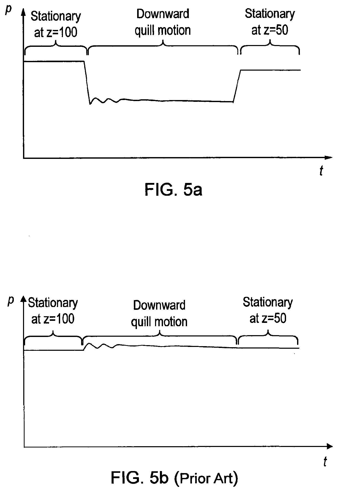
[0044] FIG. 5a is a graph illustrating how the counterbalance mechanism's pneumatic pressure might vary over time during a downward quill motion in accordance with one aspect of the invention and FIG. 5b is a graph illustrating how the counterbalance mechanism's pneumatic pressure might vary over time during the same downward quill motion in a system of the art.
[0045] An overview of an example embodiment of how the invention can be implemented will be described below. In this case, the invention is implemented as part of a CMM 100. FIG. 1 shows a CMM 100 with its protective housings/covers (e.g. "main" covers/"hard" covers) removed so that the relevant components of the CMM 100 can be seen. FIG. 2 shows an enlarged view of the top end of the quill 110 of CMM 100.
[0046] As shown, a tool, for example an inspection device such as a probe 102 for inspecting a workpiece, can be mounted on the CMM 100. In the embodiment shown, the probe 102 is a contact probe, in particular a contact analogue scanning probe, for measuring the workpiece by a stylus of the probe contacting the workpiece. However, as will be understood the CMM 100 could carry any sort of inspection device, including touch-trigger probes, non-contact (e.g. optical) probes, or another type of instrument if desired.
[0047] In the embodiment shown, the CMM 100 is a gantry-style Cartesian CMM and comprises a platform 105 on which an artefact to be inspected can be placed, and a movement system which provides for repeatable and accurate control of the position of the probe 102 relative to the platform 105 in three orthogonal degrees of freedom X, Y and Z.
[0048] In particular, the movement system comprises a cross-beam 106, a carriage 108, and a quill 110. The cross-beam 106 extends between first 112 and second 114 raised rail members and is configured to move along the rails along a Y axis via a bearing arrangement (in this embodiment an air bearing arrangement--not shown), and powered by a motor, such as a linear motor (not shown). The carriage 108 sits on and is carried by the cross-beam 106, and is moveable along the cross-beam along an X axis via a bearing arrangement (in this embodiment an air bearing arrangement--not shown) and powered by a motor, such as a linear motor (not shown). The quill 110 is held by the carriage 108, and is moveable relative to the carriage 108 along a Z axis via a bearing arrangement (again, in this embodiment via an air bearing arrangement--not shown), and powered by a motor, such as a linear motor. The stator 400 of the quill's linear motor is visible in FIGS. 1 and 2, but the armature 402 (see FIG. 3) is not visible in FIGS. 1 and 2. As will be understood, the stator 400 is fixed relative to the carriage 108 (e.g. it can be anchored at a lower end to the carriage 108 and at an upper end to a tower 194 which is mounted to the carriage 108 so as to move therewith), and the armature 402 can be fixed and mounted to the quill 110 so as to move therewith.
[0049] A pneumatic counterbalance mechanism for the quill is provided for counterbalancing the weight of the quill 110 so as to reduce the work required of the quill's motor. In particular, the pneumatic counterbalance is configured to provide an opposing force substantially equal to the weight of the quill 110 (and the articulated head 116 and probe 102) such that substantially zero force is required by the quill's motor to keep it at a stationary position. The quill 110 is hollow and the pneumatic counterbalance comprises a piston 300 within a counterbalance cylinder 302 located inside the quill 110 (see FIG. 3). The piston 300 is anchored to a tower 194 (in this case a carbon-fibre tube) via a cable 196. The tower 194 is mounted to the carriage 108 so as to move therewith. As described in more detail below, in accordance with the invention, the apparatus is configured to adapt the pneumatic counterbalance automatically in response to certain circumstances so as to alter the counterbalance force provided.
[0050] As will be understood, motors, for example direct drive motors such as linear motors, can be provided for effecting the relative motion of the various members along their axis (of which the stator 400 of the quill's linear motor is shown in FIGS. 1 and 2). Also, position encoders can be provided for reporting the position of the cross-beam 106, carriage 108 and/or quill 110. The scale 404 and readhead 406 of the quill's linear encoder are visible in FIGS. 1 and 2. The linear motor and encoder arrangement for driving and monitoring the position of the quill 110 is also schematically shown and described in more detail below in connection with FIG. 3.
[0051] In the particular example shown, an articulated head 116 is provided on the lower free end of the quill 110 for carrying the probe 102. In this case, the articulated head 116 comprises two orthogonal rotational axes. Accordingly, in addition to the three orthogonal linear degrees of freedom X, Y and Z, the probe 102 can be moved about two orthogonal rotational axes (e.g. A and B axes). A machine configured with such an articulated head is commonly known as a 5-axis machine.
[0052] Articulated heads for tools and inspection devices are well known, and for example described in WO2007/093789. As will be understood, an articulated head need not necessarily be provided, and for example the probe 102 could be mounted to the quill assembly 110 via a fixed head which does not provide any rotational degrees of freedom. Optionally, the probe itself can comprise an articulated member so as to facilitate rotation about at least one axis.
[0053] An energy conduit 502 is provided between the quill 110 and the carriage 108. The energy conduit 502 comprises one or more electrical wires and/or pipes for providing power, communications, and/or gas, to and/or from the quill 110, the articulated probe head 116, and the probe 102. For example, the pipe(s) could supply gas for the quill's air bearings (not shown) and/or for the pneumatic counterbalance. For the sake of clarity, most of the wires and pipes are not shown in the Figures; only the pipe 420 for supplying air to the inside of the quill 110 for the pneumatic counterbalance mechanism is shown in FIGS. 2 and 3. In any case, in this embodiment, in addition to the wires and pipes, the energy conduit 502 comprises a support track 503 which flexes with relative movement of the quill 110 and carriage 108. The support track 503 is configured to keep the wires and pipes associated with it tidy and to control how they flex with the relative movement of the quill 110 and carriage 108. A first end of the support track 503 of the energy conduit 502 is connected to the carriage 108 (in this case to the carriage's tower 194, via bracket 195), and a second end of the support track 503 of the energy conduit 502 is connected to the quill 110 (in this case via a bracket 198).
[0054] As is standard with measuring apparatus, a controller 118 can be provided which is in communication with the CMM's motors and position encoders, the articulated head 116 (if present) and the probe 102 so as to send and/or receive signals to and/or from them so as to control the motion of the relatively moveable members as well as receive feedback and measurement data. A computer 120, e.g. a personal computer (which can be separate to or integrated with the controller 118) can be provided which is in communication with the controller 118. The computer 120 can provide a user-friendly interface for an operator to, for example, program and initiate measurement routines. Suitable computers and associated control/programming software is widely available and well known. Furthermore, a joystick 122 or other suitable input device can be provided which enables an operator to manually control the motion of the probe 102. Again, such joysticks are well known and widely available.
[0055] A variety of tools/inspection devices could be stored in a rack 450 located within the CMM's working volume. Furthermore, the probe 102 mounted on the CMM 100 could be automatically changed to/from the rack 450 in a known manner.
[0056] Referring now to FIG. 3, a cross-section of the CMM's quill 110 is schematically shown. As shown, a linear motor and encoder apparatus are provided for effecting and monitoring movement of the quill 110 along the z-axis relative to the carriage 108 (which is not shown in FIG. 3). In particular, in this embodiment, the linear motor comprises an elongate stator 400 fixed relative to the carriage 108 (not shown) (in particular, the linear motor is fixed at a bottom end to the carriage's box structure, and at a top end to the carriage's tower 194--neither shown in FIG. 3) and an armature 402 fixed to the quill 110. In this embodiment the encoder comprises a scale 404 fixed to the quill 110 and a readhead 406 fixed to the carriage 108 for reading the scale. As will be understood, the stator 400 and armature 402 could be mounted the other way around (i.e. the armature could be mounted to the carriage, and the stator to the quill), and likewise for the scale 404 and readhead 406.
[0057] FIG. 3 also schematically shows various parts of an example controller 118. In particular, in this example, there is shown a main processing unit (e.g. main processing board) 410, an encoder interface 412, a motor power amplifier 414 and a counterbalance controller 416. As will be understood, these various units/interfaces/amplifiers could be provided as separate or as combined components (e.g. on the same or different boards and/or via the same or different processors/circuitry) and need not all be provided in or by the controller 118 (e.g. the counterbalance controller could be located separate from the controller 118. As will also be understood, the circuitry for such units/interfaces/amplifiers could comprise bespoke or generic processor units, e.g. microprocessors, central processing units (CPU), Field-Programmable Gate Arrays (FPGAs), or the like.
[0058] As also shown, a pressurised gas supply 418 such as a pneumatic pump or, for example, a compressed gas supply is provided which provides supply of pressurised gas (e.g. air) to the inside of the quill 110, e.g. via pipe 420 (which is supported by the support track of the energy conduit 502). The pressurised gas inside the counterbalance cylinder 302 acts against the piston 300 and the inside walls of the counterbalance cylinder 302 so as to provide an upwards force along the z-axis, thereby supporting at least some (and preferably substantially all) of the weight of the quill 110 and any components mounted thereon, such as the articulated probe head 116 and the probe 102. The pressurised gas supply 418 could be configured to try to maintain a set pressure within the counterbalance cylinder 302, e.g. the apparatus, for example the pressurised gas supply, could comprise a pressure regulator, such as a digital pressure regulator.
[0059] According to an example embodiment, during normal use, the controller 118 is configured to control the x, y and z axes of the CMM 100, and for example the rotational positions of the articulated head's 116 rotational axes. For example, this could be in response to signals received from an input device, such as the joystick 122 and/or computer 120. Optionally, the controller 118 (e.g. the main processing unit 410) could execute a program comprising a predefined course of motion, and control the axes of the CMM 100 and articulated head 116 accordingly. As shown in FIG. 3 in connection with the z-axis, the controller 118 can effect movement of the z-axis by way of the main processing unit 410 instructing commands to the motor power amplifier 414 which in turn powers the armature 402 so as to operate the linear motor. The controller 118, by way of the main processing unit 410, readhead 406, encoder interface 412 and the motor power amplifier 414, can operate to implement a servo loop, so as to ensure that the quill 110 is moving toward or at the desired position.
[0060] As briefly mentioned above, in accordance with the invention, the apparatus is configured to adapt the pneumatic counterbalance automatically in response to certain circumstances so as to alter the counterbalance force it provides. This has been found to be particularly beneficial to CMMs where a direct drive, such as a linear motor, is used to control the z-axis position of the quill 110. This is because the effect of the heat generated by such motors on the metrological performance of the CMM can be more pronounced due to direct drive, and in particular linear motors, typically being mounted closer to the CMM's metrology structure. Also, in contrast to other types of motors, such as ball-screw or geared systems, which cannot be back-driven, it is often necessary to power a direct drive/linear motor, to hold a given position should the counterbalance mechanism not counterbalance the load on the quill, thereby producing heat even when stationary. If the power required to hold position is different for different positions, then the amount of heat generated may be different for different positions, thereby affecting metrology differently in different positions. Accordingly, avoiding significant changes in the power requirement of a direct drive/linear motor (and hence avoiding significant changes heat generated by the motor) can be more important to the metrological performance of the CMM compared to belt driven, ball-screw, or geared DC motors.
[0061] Accordingly, in one embodiment, the apparatus is configured to adapt the pneumatic counterbalance's pneumatic pressure automatically depending on the z-axis position of the quill 110. The mass, and hence weight, carried by the quill 110 can vary depending on the z-axis position, for example due to the proportion of the energy conduit 502 that is carried by the quill 110. For example, in this embodiment, this could be due to the proportion of the energy conduit 502 that is carried by the quill 110 being greater in a relatively raised/higher position compared to which it is in a relatively lowered position. Accordingly, the linear motor will have to work harder just to hold position at a first vertical/z-axis position compared to a second vertical/z-axis position. This means that the linear motor will generate more heat at the first vertical/z-axis position compared to when it is the second vertical/z-axis position. Such variation in heat output can adversely affect metrology. As will be understood, the first vertical/z-axis position could be higher than the second vertical/z-axis position, or the first vertical/z-axis position could be lower than the second vertical/z-axis position.
[0062] It might also be that irrespective of the energy conduit 502 (e.g. even if the energy conduit 502 is substantially balanced by a corresponding second energy conduit 504 as in FIG. 4), the power requirement of the motor could vary depending on the z-axis position, due to, for example, hysteresis in the energy conduit, varying cable tension, etc. Accordingly, such variations could be determined (e.g. mapped) during a calibration stage and subsequently used by the counterbalance controller 416 to control the pressurised gas supply 418 accordingly. For example, a function or map could be determined during the calibration stage. Such a function/map could be configured so as to try to ensure that substantially the same motor power (which could be substantially zero motor power) is required to hold the quill 110 at all z-axis position, or at least for a significant proportion of the quill's z-axis position (e.g. for at least 50%, preferably at least 75% of the quill's z-axis travel range).
[0063] According to one aspect of the invention, the counterbalance controller 416 receives an input from the encoder interface 412 which indicates the current z-axis position of the quill 110. The counterbalance controller 416 can then use this input to determine how to control the pressurised gas supply 418 so as to vary the pressure of the gas within the counterbalance cylinder 302 accordingly. For example, based on the input from the encoder interface 412, the counterbalance controller 416 can be configured such that it controls the pressurised gas supply 418 to ensure a relatively greater pressure inside the counterbalance cylinder 302 for relatively higher positions of the quill 110, and to control the pressurised gas supply 418 to ensure a relatively lower pressure inside the counterbalance cylinder 302 for relatively lower positions of the quill 110, or vice versa. If the pressurised gas supply 418 comprises a pressure regulator, the counterbalance controller 416 could be configured to change the pressure which the pressure regulator is set to try to maintain.
[0064] The counterbalance controller 416 could be configured to control the pressurised gas supply 418 (e.g. via changing the pressure a pressure regulator is set to achieve) so as to at least reduce any variation in the linear motor power required for holding a stationary position along the z-axis. If desired, the counterbalance controller 416 could be configured to control the pressurised gas supply 418 so as to ensure that the linear motor power required for holding a stationary position is substantially constant for a significant proportion of the z-axis. Either way, this could be achieved, for example, by the counterbalance controller 416 using the input from the encoder interface 412 to, for example, look up in a pre-calibrated table, or determine via a predetermined function, a particular setting (e.g. a particular gas pressure), which is then used to automatically determine how to control the pressurised gas supply 418.
[0065] As will be understood, in an alternative embodiment, the counterbalance controller 416 could automatically determine how to control the pressurised gas supply 418 based on an input from the main processing unit 410 (or the motor power amplifier 414). The input from the main processing unit could indicate the actual and/or demanded position of the quill 110. This could be rather than, or in addition to, an input of the position of the quill 110 from the encoder interface 412.
[0066] In another embodiment, the apparatus is configured to adapt the pneumatic counterbalance automatically depending on what is mounted on the end of the quill 110 (e.g. depending on the tool/probe mounted on the quill 110). This could be so as to adjust the pressure of the gas inside the counterbalance cylinder 302 automatically so as to adjust for any change in weight caused by the change in probe loaded on the quill 110, and therefore avoid a change in the work required of the linear motor (e.g. to ensure that counterbalance continues to substantially counterbalance the total weight of the quill and what it carries). This can be particularly significant when an optical probe, such as a camera or video probe is loaded on the quill 110, because such probes can have relatively heavy imaging optics.
[0067] For example, when a new probe is mounted on the articulated head 116 from the rack 450, the counterbalance controller 416 can receive an input indicative of the change. For instance, the counterbalance controller 416 could receive an input from the main processing unit 410 which indicates what probe is now (or is about to be) loaded on the quill 116. The counterbalance controller 416 could then use this input to look up in a preconfigured table, one or more parameters related to the weight of the probe, and then instruct the pressurised gas supply 418 to change the pressure of the gas inside the counterbalance cylinder 302 accordingly. In an alternative embodiment, the main processing unit 410 could provide the counterbalance controller 416 one or more parameters related to the weight of the probe (rather than the counterbalance controller 416 having to look it up).
[0068] In another alternative embodiment, in response to the counterbalance controller 416 receiving an input which indicates that a probe change has taken place, the counterbalance controller 416 could determine the effect of the module on the coordinate positioning apparatus and thereby determine how to control the pressurised gas supply 418 so as to change the pressure of the gas inside the quill 110 accordingly adjust the pressure accordingly. For example, the counterbalance controller 416 could initiate a "weighing operation" to determine a parameter relative to the weight of the probe loaded on the quill 110. For example, this could comprise the main processing unit 410 controlling the quill's z-axis position in a particular predetermined way (such as keeping the quill 110 in a stationary position, moving the quill up and/or down, and/or for accelerating the quill 110 over a known distance) and determining from the motor power amplifier 414 what the power requirement is for performing such control. The power requirement (or one or more parameters indicative of the power requirement) can be input to the counterbalance controller 416 (e.g. optionally via the main processing unit 410) to determine a parameter related to weight of the probe. As another example, the main processing unit 410 could control the motor power amplifier 414 to move the quill 110 with a particular force. The acceleration of the quill 110 could be measured. This would enable the mass/load of the quill (or a parameter related thereto) to be determined. In any case, the counterbalance controller 416 could then use the information from any or a combination of such above described routines to determine how to control the pressurised gas supply 418 so as to change the pressure of the gas inside the counterbalance cylinder 302 accordingly.
[0069] The above described embodiment requires determining a parameter related to the weight of the probe. Such a parameter could be the weight of the probe (e.g. in a unit of weight, such as grams). However, as will be understood, this need not necessarily be the case. For example, a parameter which is dependent on/indicative of the weight could be identified instead. For example, rather than using a look-up table to determine the weight of a probe loaded (or to be loaded) on the quill 110, the look-up table could be used to determine what setting (e.g. what air pressure) the pressurised gas supply 418 should be set to depending on the probe loaded (or to be loaded) on the quill 110. As another example, the "weighing operation" could merely determine a particular setting (e.g. what air pressure) the pressurised gas supply 418 should be set to, rather than actually determining the weight (in a unit of weight) of the probe.
[0070] In another embodiment, the counterbalance controller 416 could be configured to automatically control the pressurised gas supply 418 so as to adjust the pressure inside the counterbalance cylinder 302 depending on the direction motion of the quill 110. For instance, in the described embodiment when the quill 110 is moving upward gas the pressure within the counterbalance cylinder 302 could be increased, and when the quill 110 is moving downward the pressure within the counterbalance cylinder 302 could be reduced, thereby assisting the linear motor. Accordingly, the counterbalance controller 416 could receive an input from the controller 410 indicating a direction in which the quill 110 is moving, and the counterbalance controller 416 could control the pressurised gas supply 418 so as to adjust the supply of pressurised gas accordingly (e.g. by adjusting the pressure a pressure regulator of the pressurised gas supply 418 is set to maintain). For instance, if the counterbalance controller 416 receives an input from the controller 410 indicating that the quill 110 is moving, or is about to move, upwards, the counterbalance controller 416 can control the pressurised gas supply 418 so as to increase the pressure inside the counterbalance cylinder 302, whereas if the counterbalance controller 416 receives an input from the controller 410 indicating that the quill 110 is moving downwards, the counterbalance controller 416 can control the pressurised gas supply 418 so as to decrease the pressure inside the counterbalance cylinder 302. As will be understood, rather than waiting for the movement to occur before adjusting the pressure, the counterbalance controller 416 could pre-empt a future motion by adjusting the pressure shortly before the motion is due to occur.
[0071] An example of how pressure within the counterbalance cylinder 302 might vary over time when implementing this aspect of the invention is illustrated in FIG. 5a. As shown, when the quill 110 is stationary at a notional axial position of Z=100, the pressure is maintained at a first constant set (i.e. target) pressure (e.g. 5 bar). However, when the quill is about to be moved downwards, the counterbalance controller 416 (on the basis of an input from the controller 410) can know in advance that such motion is to take place and thereby control the pressurised gas supply 418 so as to decrease the set (i.e. target) pressure inside the counterbalance cylinder 302 during such motion (e.g. 4.5 bar) so as to assist the linear motor (e.g. to reduce the motor power requirement, or to increase the travel speed for a given motor power/current). On returning to a stationary position, the counterbalance controller 416 (on the basis of an input from the controller 410) can bring the pressurised gas supply 418 back up to a level where it substantially counterbalances the total load on the quill. As shown, in this case (and in accordance with the other above described aspect of the invention), the counterbalance controller 416 does not return the pressure back to the same set (i.e. target) pressure, but instead to a slightly different set (i.e. target) pressure (e.g. 4.9 bar) because the total load on the quill is different at this different z-axis position (e.g. because the quill 100 is carrying less of the energy track at this new z-axis position). As also shown, during the motion there might be some small fluctuation in the actual pressure within the counterbalance cylinder 302 due to lag/hysteresis in the pressure regulator which is trying to maintain the pressure at the new set level of 4.5 bar.
[0072] The graph of FIG. 5a is to be contrasted with the graph of FIG. 5b which illustrates the how pressure within the counterbalance cylinder 302 might vary over time when using a known pressure regulator which is configured to maintain a set (i.e. target) pressure of a pneumatic counterbalance system. As shown, in this case, the system is configured such that the at all times (i.e. when stationary and during motion), the same pressure is maintained within the counterbalance cylinder 302. As shown, there might be some initial fluctuations during the motion due to lag/hysteresis in the pressure regulator, but nominally the pressure is the same, and in contrast to the present invention, as illustrated in FIG. 5a, the system is configured such that the pressure is maintained constant in all circumstances.
[0073] In the above described embodiments, the counterbalance controller 416 is shown as having dedicated inputs from the various other units/interfaces/amplifiers in the controller 118. However, as will be understood, this need not necessarily be the case and other configurations are possible. For example, the counterbalance controller 416 could receive a single input from the main processing unit 410 (e.g. which could relay signals from the encoder interface 412 and/or amplifier 412). Optionally, the counterbalance controller is provided by the main processor unit 410 (i.e. in which case the unit 416 as a separate entity need not exist).
[0074] Optionally, the main processing unit 410 communicates with, and controls, the pressurised gas supply 418 directly (this could be the case when the unit 416 as a separate entity does or does not exist).
* * * * *
D00000
D00001
D00002
D00003
D00004
D00005
XML
uspto.report is an independent third-party trademark research tool that is not affiliated, endorsed, or sponsored by the United States Patent and Trademark Office (USPTO) or any other governmental organization. The information provided by uspto.report is based on publicly available data at the time of writing and is intended for informational purposes only.
While we strive to provide accurate and up-to-date information, we do not guarantee the accuracy, completeness, reliability, or suitability of the information displayed on this site. The use of this site is at your own risk. Any reliance you place on such information is therefore strictly at your own risk.
All official trademark data, including owner information, should be verified by visiting the official USPTO website at www.uspto.gov. This site is not intended to replace professional legal advice and should not be used as a substitute for consulting with a legal professional who is knowledgeable about trademark law.