Air Conditioning System And Air Conditioner
HONG; Zhirong ; et al.
U.S. patent application number 16/620017 was filed with the patent office on 2020-05-14 for air conditioning system and air conditioner. The applicant listed for this patent is GD MIDEA HEATING & VENTILATING EQUIPMENT CO., LTD. MIDEA GROUP CO., LTD.. Invention is credited to Zhirong HONG, Yiyang MO, Ming SONG, Fudang WEI, Yuzhao ZHANG.
| Application Number | 20200149789 16/620017 |
| Document ID | / |
| Family ID | 59836410 |
| Filed Date | 2020-05-14 |

| United States Patent Application | 20200149789 |
| Kind Code | A1 |
| HONG; Zhirong ; et al. | May 14, 2020 |
AIR CONDITIONING SYSTEM AND AIR CONDITIONER
Abstract
A novel air conditioning system includes a compressor; an outdoor heat exchanger; an indoor heat exchanger; and a four-way valve arranged among the compressor, the outdoor heat exchanger, and the indoor heat exchanger and configured to switch to a cooling mode and a heating mode; a first separator connected between the outdoor heat exchanger and the indoor heat exchanger; an auxiliary branch connected to the indoor heat exchanger in parallel and arranged between the gas-liquid separator and the four-way valve. With the first separator, the gaseous refrigerant and the liquid refrigerant is separated, and the gaseous refrigerant is directly bypassed to an outlet of the evaporator by means of the auxiliary branch between the first separator 108 and the four-way valve, thereby reducing the resistance to the refrigerant flowing in the evaporator and raising the energy efficiency of the system.
| Inventors: | HONG; Zhirong; (Foshan, CN) ; SONG; Ming; (Foshan, CN) ; ZHANG; Yuzhao; (Foshan, CN) ; WEI; Fudang; (Foshan, CN) ; MO; Yiyang; (Foshan, CN) | ||||||||||
| Applicant: |
|
||||||||||
|---|---|---|---|---|---|---|---|---|---|---|---|
| Family ID: | 59836410 | ||||||||||
| Appl. No.: | 16/620017 | ||||||||||
| Filed: | January 10, 2018 | ||||||||||
| PCT Filed: | January 10, 2018 | ||||||||||
| PCT NO: | PCT/CN2018/072043 | ||||||||||
| 371 Date: | December 6, 2019 |
| Current U.S. Class: | 1/1 |
| Current CPC Class: | F24F 1/0007 20130101; F25B 30/02 20130101; F25B 41/046 20130101; F25B 43/00 20130101; F25B 41/06 20130101; F25B 2400/0409 20130101; F25B 41/067 20130101; F25B 2313/02741 20130101; F25B 2400/23 20130101; F25B 41/043 20130101; F25B 13/00 20130101; F24F 1/32 20130101 |
| International Class: | F25B 30/02 20060101 F25B030/02; F24F 1/0007 20060101 F24F001/0007; F24F 1/32 20060101 F24F001/32; F25B 41/04 20060101 F25B041/04; F25B 43/00 20060101 F25B043/00; F25B 41/06 20060101 F25B041/06 |
Foreign Application Data
| Date | Code | Application Number |
|---|---|---|
| Jun 12, 2017 | CN | 201710436846.3 |
Claims
1. An air conditioning system, comprising: a compressor (102); an outdoor heat exchanger (112); an indoor heat exchanger (120); a four-way valve (114) arranged among the compressor (102), the outdoor heat exchanger (112), and the indoor heat exchanger (120) and configured to switch to a cooling mode and a heating mode; a first separator (108) connected between the outdoor heat exchanger (112) and the indoor heat exchanger (120) and having a first port connected to a line of the outdoor heat exchanger (112) and a second port (106) connected to a line of the indoor heat exchanger (120); and an auxiliary branch connected to the indoor heat exchanger in parallel and arranged between a gas-liquid separator and the four-way valve (114) and having an end connected to a third port (122) of a gas-liquid separator, the third port (122) of the gas-liquid separator being configured as an outlet for a gaseous phase.
2. The air conditioning system according to claim 1, wherein the auxiliary branch comprises a capillary (116) and a the one-way valve (118) connected to each other in series, when the refrigerant flows from the gas-liquid separator to the four-way valve (114), the one-way valve (118) is in communication.
3. The air conditioning system according to claim 2, further comprises a second separator (104) arranged between the four-way valve (114) and the compressor (102), the second separator (104) implement gas-liquid separation to the refrigerant flowing into the compressor (102).
4. The air conditioning system according to claim 3, wherein the four-way valve (114) comprises: a first valve port connected to a discharge port line of the compressor (102); a second valve port connected to the outdoor heat exchanger (112); a third valve port connected to an inlet of the second separator (104), wherein the refrigerant is discharged into a return port of the compressor (102) after passing through an outlet of the second separator (104) and a line; and the fourth valve port connected to the indoor heat exchanger (120).
5. The air conditioning system according to claim 4, further comprising a microcontroller electrically coupled with the four-way valve (114), wherein when the air conditioning system is in the cooling mode, the microcontroller controls the first valve port and the second valve port of the four-way valve (114) to be in communication with each other, and controls the third valve port and the fourth valve port of the four-way valve (114) to be in communication with each other; and when the air conditioning system is in the heating mode, the microcontroller controls the first valve port and the fourth valve port of the four-way valve (114) to be in communication with each other, and controls the second valve port and the third valve port of the four-way valve (114) to be in communication with each other,
6. The air conditioning system according to claim 1, wherein the auxiliary branch comprises a one-way throttle valve arranged on the auxiliary branch, the one-way throttle valve makes the refrigerant flow in one direction from the first separator (108) to the four-way valve (114).
7. The air conditioning system according to claim 1, further comprises a throttle member (110) arranged on a line connecting the outdoor heat exchanger (112) to the first port of the first separator (108), the throttle member (110) cools and depressurizes the refrigerant flowing in the line connecting the outdoor heat exchange (112) to the first separator (108).
8. An air conditioner, comprising the air conditioning system according to claim 1.
9. The air conditioner according to claim 8, further comprising a signal receiver electrically coupled with a microcontroller in the air conditioning system, the signal receiver receives an external signal and sends a control signal to the microcontroller, and the microcontroller switches an operation mode of the air conditioner in response to the control signal.
10. The air conditioner according to claim 9, wherein the signal receiver comprises an infrared sensor, a Bluetooth receiver, and a WIFI receiver.
11. The air conditioning system according to claim 2, further comprises a throttle member (110) arranged on a line connecting the outdoor heat exchanger (112) to the first port of the first separator (108), the throttle member (110) cools and depressurizes the refrigerant flowing in the line connecting the outdoor heat exchanger (112) to the first separator (108).
12. An air conditioner, comprising the air conditioning system according to claim 2.
13. The air conditioning system according to claim 3, further comprises a throttle member (110) arranged on a line connecting the outdoor heat exchanger (112) to the first port of the first separator (108), the throttle member (110) cools and depressurizes the refrigerant flowing in the line connecting the outdoor heat exchanger (112) to the first separator (108).
14. An air conditioner, comprising the air conditioning system according to claim 3.
15. The air conditioning system according to claim 4, further comprises a throttle member (110) arranged on a line connecting the outdoor heat exchanger (112) to the first port of the first separator (108), the throttle member (110) cools and depressurizes the refrigerant flowing in the line connecting the outdoor heat exchanger (112) to the first separator (108).
16. An air conditioner, comprising the air conditioning system according to claim 4,
17. The air conditioning system according to claim 5, further comprises a throttle member (110) arranged on a line connecting the outdoor heat exchanger (112) to the first port of the first separator (108), the throttle member (110) cools and depressurizes the refrigerant flowing in the line connecting the outdoor heat exchanger (112) to the first separator (108).
18. An air conditioner, comprising the air conditioning system according to claim 5.
19. The air conditioning system according to claim 7, further comprises a throttle member (110) arranged on a line connecting the outdoor heat exchanger (112) to the first port of the first separator (108), the throttle member (lit)) cools and depressurizes the refrigerant flowing in the line connecting the outdoor heat exchanger (112) to the first separator (108).
20. An air conditioner, comprising the air conditioning system according to claim 7.
Description
FIELD
[0001] The present disclosure relates to a technical field of temperature control apparatuses, and particularly, to an air conditioning system and an air conditioner.
BACKGROUND
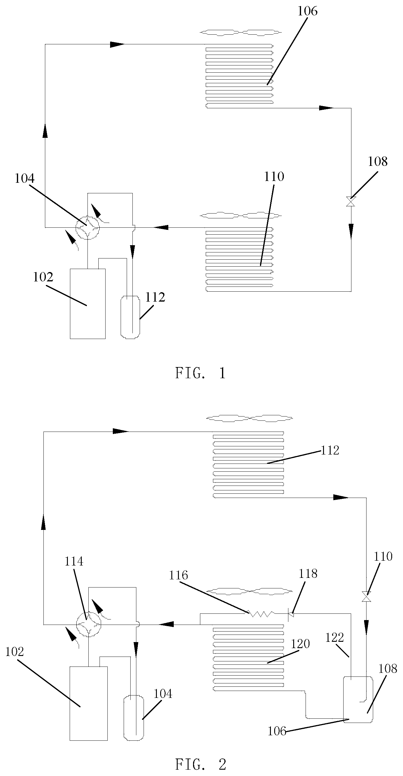
[0002] At present, a common air conditioning system is consist of a compressor 101, a four-way valve 104, an outdoor heat exchanger 106, a throttle component 108, an indoor heat exchanger 110, and a low-pressure tin 112, as shown in FIG. 1. Most of refrigerant is located in a condenser, and a few of the refrigerant is located in an evaporator during operation of the system due to differences between status parameters of the refrigerant, such as pressures, temperatures, etc.
[0003] Regarding the air conditioning system, the condenser is the outdoor heat exchanger 106 and the evaporator is the indoor heat exchanger 110 during cooling, while the condenser is the indoor heat exchanger 110 and the evaporator is the outdoor heat exchanger 106 during heating.
[0004] According to characteristics of heating and heating switching of a heat-pump air conditioner, a certain relation between sizes of inside volumes of an indoor heat exchanger and an outdoor heat exchanger is required. If the inside volume of the indoor heat exchanger 110 is undersized, too much refrigerant is charged during heating, resulting in undesirable operation of the system.
SUMMARY
[0005] The present disclosure seeks to solve at least one of the problems existing in the prior art or the related art.
[0006] To this end, an objective of the present disclosure is to provide an air conditioning system.
[0007] Another objective of the present disclosure is to provide an air conditioner.
[0008] To achieve the above objectives, technical schemes of a first aspect of the present disclosure provide an air conditioning system including: a compressor; an outdoor heat exchanger; an indoor heat exchanger; a four-way valve arranged among the compressor, the outdoor heat exchanger, and the indoor heat exchanger and configured to switch to a cooling mode and a heating mode; a first separator connected between the outdoor heat exchanger and the indoor heat exchange and having a first port connected to a line of the outdoor heat exchanger and a second port connected to a line of the indoor heat exchanger; and an auxiliary branch connected to the indoor heat exchanger in parallel and arranged between a gas-liquid separator and the four-way valve and having an end connected to a third port of a gas-liquid separator, the third port of the gas-liquid separator being configured as an outlet for a gaseous phase.
[0009] In the technical scheme, by arranging the first separator between the outdoor heat exchanger and the indoor heat exchanger, during cooling operation the compressor discharges high-temperature high-pressure vapor, and the high-temperature high-pressure vapor flows into the outdoor heat exchanger through the four-way valve, a refrigerant in the outdoor heat exchanger has a part condensed into liquid and another part in a gaseous state, and the refrigerant in two phases, i.e. a gaseous phase and a liquid phase, is separated into a gaseous refrigerant and a liquid refrigerant in the first separator. After separation, the gaseous refrigerant reaches an outlet of the indoor heat exchanger through the second port of the first separator, and the liquid refrigerant enters an evaporator through the first port of the first separator for heat exchanging by means of evaporation, and is mixed with the gaseous refrigerant coming from bypass at an outlet of the evaporator. After mixing, the refrigerant vapor enters a low-pressure tin through the four-way valve and return to the compressor. Since the gaseous refrigerant is large in specific volume, a large flow resistance is caused, the energy efficiency of the system is greatly raised by means of the auxiliary branch. In addition, during heating operation, the refrigerant entering the first separator through the indoor heat exchanger is in the liquid state, meanwhile the first separator can store a great amount of the refrigerant, the possibility that too much refrigerant is charged during heating due to the indoor heat exchanger of a small volume is reduced.
[0010] In addition, the air conditioning system in the above technical scheme provided by the present disclosure also can have the additional technical features as follows.
[0011] In the above technical scheme, preferably, the auxiliary branch includes a capillary and a the one-way valve connected to each other in series, when the refrigerant flows from the gas-liquid separator to the four-way valve, the one-way valve is in communication.
[0012] In this technical scheme, with the capillary and the one-way valve connected in series, when the refrigerant flows from the gas-liquid separator to the four-way valve, that more refrigerant in the gas-liquid separator is evaporated into the gaseous state and goes to the outlet of the evaporator through a bypass branch due to excessive-low loss of pressure in the bypass branch can be prevented by the one-way valve in communication, which otherwise results in extra loss of refrigeration capacity. During heating, the compressor discharges high-temperature high-pressure refrigerant vapor, and the high-temperature high-pressure refrigerant vapor flows to the indoor heat exchanger through the four-way valve, the high-temperature high-pressure vapor cannot enter the gas-liquid separator through the auxiliary branch because of the characteristic of one-way communication of the one-way valve, thereby reducing waste in heat energy.
[0013] In any one of the above technical schemes, preferably, a second separator is further provided and arranged between the four-way valve and the compressor, the second separator implement gas-liquid separation to the refrigerant flowing into the compressor.
[0014] In this technical scheme, by arranging the second separator between the four-way valve and the compressor, the gaseous refrigerant and the liquid refrigerant which flow into the compressor are separated, the unnecessary liquid is stored, so as to reduce a great amount of liquid flowing into the compressor, and thereby regulating the flow.
[0015] In any one of the above technical schemes, preferably, the four-way valve includes: a first valve port connected to a discharge port line of the compressor; a second valve port connected to the outdoor heat exchanger; a third valve port connected to an inlet of the second separator, wherein the refrigerant is discharged into a return port of the compressor after passing through an outlet of the second separator and a line; and the fourth valve port connected to the indoor heat exchanger.
[0016] In this technical scheme, switching of cooling and heating can be completed quickly by opening and closing the four valve ports of the four-way valve, raising the efficiency and simplifying operation. During a cooling cycle, the high-temperature high-pressure vapor discharged from the compressor enters the outdoor heat exchanger through the first valve port and the second valve port, and the first separator separates gas and liquid after condensation. The liquid refrigerant enters the evaporator from the first separator for heat exchanging and is mixed with the gaseous refrigerant from the auxiliary branch, and then returns to the compressor through the third valve port and the fourth valve port of the four-way valve to complete the cooling cycle. During a heating cycle, the high-temperature high-pressure vapor discharged from the compressor enters the indoor heat exchanger through the first valve port and the fourth valve port, and the first separator separates gas and liquid after condensation. The refrigerant enters the evaporator and is evaporated through absorption of heat, and after evaporation the refrigerant vapor is mixed with the gaseous refrigerant flowing through an auxiliary branch of the four-way valve, enters the second separator through the second valve port and the third valve port of the four-way valve, and finally enters the compressor to complete the heating cycle.
[0017] In any one of the above technical schemes, preferably, a microcontroller is further provided and electrically coupled with the four-way valve, when the air conditioning system is in the cooling mode, the microcontroller controls the first valve port and the second valve port of the four-way valve to be in communication with each other, and controls the third valve port and the fourth valve port of the four-way valve to be in communication with each other; and when the air conditioning system is in the heating mode, the microcontroller controls the first valve port and the fourth valve port of the four-way valve to be in communication with each other, and controls the second valve port and the third valve port of the four-way valve to be in communication with each other.
[0018] In this technical scheme, with the microcontroller electrically coupled with the four-way valve, during the cooling mode, the first valve port and the second valve port of the four-way valve are controlled to be in communication with each other, the high-temperature high-pressure vapor discharged from the compressor flows into the outdoor heat exchanger to be condensed; and the third valve port is in communication with the fourth valve port, such that after vapor heat exchanging the refrigerant flows from the evaporator into the second separator. During the heating mode, the microcontroller controls the first valve port and the fourth valve port of the four-way valve to be connected to each other, such that the high-temperature high-pressure vapor discharged from the compressor flows into the indoor heat exchanger to be condensed, and the second valve port is connected to the third valve port, such that after evaporation through absorption of heat the refrigerant flows from the evaporator into the second separator.
[0019] In any one of the above technical schemes, preferably, the auxiliary branch includes a one-way throttle valve arranged on the auxiliary branch, the one-way throttle valve makes the refrigerant flow in one direction from the first separator to the four-way valve
[0020] In this technical scheme, by providing the one-way throttle valve on the auxiliary branch, the refrigerant is made flow in one direction from the first separator to the four-way valve, during the cooling mode, the gaseous refrigerant is made flow from the one-way valve to the four-way valve, thereby reducing flow resistance to the liquid refrigerant when the liquid refrigerant flows through the evaporator, and raising the energy efficiency of the system. During the heating mode, the high-temperature high-pressure refrigerant vapor discharged from the compressor flows to the indoor heat exchanger through the four-way valve, the one-way valve capable of communicating in one direction prevents the high-temperature high-pressure vapor refrigerant from entering the gas-liquid separator, thereby reducing waste in heat energy.
[0021] In any one of the above technical schemes, preferably, a throttle member is further provided and arranged on a line connecting the outdoor heat exchanger to the first port of the first separator, the throttle member cools and depressurizes the refrigerant flowing in the line connecting the outdoor heat exchanger to the first separator.
[0022] In this technical scheme, with the throttle member, the high-temperature high-pressure liquid refrigerant condensed in the outdoor heat exchanger becomes a low-temperature low-pressure refrigerant of two phases after passing through the throttle member, which is of benefit to heat exchanging of the vapor, thereby raising the energy efficiency of the system.
[0023] Technical schemes of a second aspect of the present disclosure provide an air conditioner including the air conditioning system according to any one of the above technical schemes.
[0024] In this technical scheme, by employing he air conditioning system according to any one of the above schemes, the possibility of poor operation of the system caused by that too much refrigerant is charged during heating due to an indoor heat exchanger of a small volume of a common air conditioner is reduced, and the whole energy efficiency of the air conditioner can also be raised.
[0025] In any one of the above technical schemes, preferably, a signal receiver is further provided and electrically coupled with a microcontroller in the air conditioning system, the signal receiver receives an external signal and sends a control signal to the microcontroller, and the microcontroller switches an operation mode of the air conditioner in response to the control signal.
[0026] In this technical scheme, with the signal receiver electrically coupled with the microcontroller in the air conditioning system, the external signal can be received and the control signal can be sent to the microcontroller, the microcontroller switches the operation mode in response to the control signal, thereby remotely controlling the air conditioner, providing more convenient and customer oriented adjustment and operation of the air conditioner.
[0027] In any one of the above technical schemes, preferably, the signal receiver includes an infrared sensor, a Bluetooth receiver, and a WIFI receiver.
[0028] In this technical scheme, with the different signal receivers, i.e. the infrared sensor, the Bluetooth receiver, and the WIFI receiver, various kinds of remote control can be achieved, such as remote control by means of a remote controller, remote control by voices, and remote control by means of a mobile phone, etc., which further simplifies control of the air conditioner, and improves convenience and comfort of control.
[0029] Additional aspects and advantages of embodiments of present disclosure will be given in part in the following descriptions, become apparent in part from the following descriptions, or be learned from the practice of the embodiments of the present disclosure.
BRIEF DESCRIPTION OF THE DRAWINGS
[0030] These and/or other aspects and advantages of embodiments of the present disclosure will become apparent and more readily appreciated from the following descriptions made with reference to the drawings, in which:
[0031] FIG. 1 illustrates a schematic view of a common air conditioning system in the related art.
[0032] FIG. 2 illustrates a schematic view of an air conditioning system in a cooling cycle according to an embodiment of the present disclosure.
[0033] FIG. 3 illustrates a schematic view of an air conditioning system in a heating cycle according to an embodiment of the present disclosure.
[0034] FIG. 4 illustrates a schematic view according to an embodiment of the present disclosure with an microchannel heat exchanger.
[0035] Correspondence between reference numerals in FIG. 1 and components is: 102 compressor, 104 four-way valve, 106 outdoor heat exchanger, 108 throttle component, 110 indoor heat exchanger, 112 low-pressure tin.
[0036] Correspondence between reference numerals in FIG. 2 to FIG. 4 and components is: 102 compressor, 114 four-way valve, 112 outdoor heat exchanger, 110 throttle member, 120 indoor heat exchanger, 104 second separator, 108 first separator, 118 one-way valve, 122 third port, 106 second port, 116 capillary.
DETAILED DESCRIPTION
[0037] A further detailed description is hereinafter given to the present disclosure with reference to accompanying drawings and embodiments so as to more clearly understand the above objectives, features and advantages thereof. It should be noted that, the embodiments of the application and the characteristics of the embodiments can be mutually combined under the condition of no conflict.
[0038] In the following detailed description, numerous specific details are set forth to provide a thorough understanding of the disclosure. The present disclosure may be embodied in various other embodiments different from the described embodiment. Therefore it is not intended that the scope of the disclosure be limited to the specific embodiment described hereinafter.
[0039] Air conditioning systems according to some embodiments of the present disclosure are described hereinafter referring to FIG. 2 to FIG. 4.
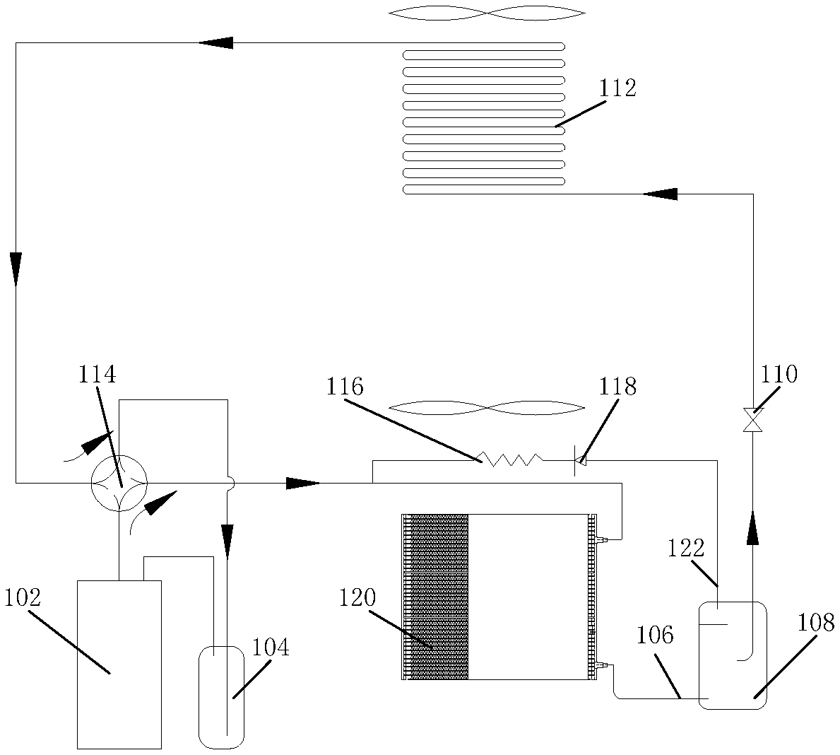
[0040] As shown in FIG. 2, an air conditioning system according to an embodiment of the present disclosure includes a compressor 102, an outdoor heat exchanger 112, an indoor heat exchanger 120, and a four-way valve 114 arranged among the compressor 102, the outdoor heat exchanger 112, and the indoor heat exchanger 120 for switching of a cooling mode and a heating mode. The air conditioning system further includes a first separator 108 connected between the outdoor heat exchanger 112 and the indoor heat exchanger 120, the first separator 108 has a first port connected to a line of the outdoor heat exchanger 112 and a second port 106 connected to a line of the indoor heat exchanger 120; and an auxiliary branch connected in parallel with the indoor heat exchanger 120, arranged between a gas-liquid separator and the four-way valve 114, and having an end connected to a third port 122 of the gas-liquid separator. The third port 122 of the gas-liquid separator is an outlet for gaseous phase.
[0041] In this embodiment, by arranging the first separator 108 between the outdoor heat exchanger 112 and the indoor heat exchanger 120, during cooling operation the compressor 102 discharges high-temperature high-pressure vapor, and the high-temperature high-pressure vapor flows into the outdoor heat exchanger 112 through the four-way valve 114, a refrigerant in the outdoor heat exchanger 112 has a part condensed into liquid and another part in a gaseous state, and the refrigerant in two phases, i.e. a gaseous phase and a liquid phase, is separated into a gaseous refrigerant and a liquid refrigerant in the first separator 108. After separation, the gaseous refrigerant reaches an outlet of the indoor heat exchanger 120 through the second port 106 of the first separator 108, and the liquid refrigerant enters an evaporator through the first port of the first separator 108 for heat exchanging by means of evaporation, and is mixed with the gaseous refrigerant coming from bypass at an outlet of the evaporator. After mixing, the refrigerant vapor enters a low-pressure tin through the four-way valve 114 and return to the compressor 102. Since the gaseous refrigerant is large in specific volume, a large flow resistance is caused, the energy efficiency of the system is greatly raised by means of the auxiliary branch. In addition, during heating operation, the refrigerant entering the first separator 108 through the indoor heat exchanger 120 is in the liquid state, meanwhile the first separator 108 can store a great amount of the refrigerant, the possibility that too much refrigerant is charged during heating due to the indoor heat exchanger 120 of a small volume is reduced.
[0042] In addition, the air conditioning system of the above embodiment provided by the present disclosure can further have the additional features as follows.
[0043] In the above embodiment, preferably, the auxiliary branch includes a capillary 116 and a one-way valve 118 connected in series, and the one-way valve 118 is in communication when the refrigerant flows from the gas-liquid separator to the four-way valve 114.
[0044] In this embodiment, with the capillary 116 and the one-way valve 118 connected in series, when the refrigerant flows from the gas-liquid separator to the four-way valve 114, that more refrigerant in the gas-liquid separator is evaporated into the gaseous state and goes to the outlet of the evaporator through a bypass branch due to excessive-low loss of pressure in the bypass branch can be prevented by the one-way valve 118 in communication, which otherwise results in extra loss of refrigeration capacity. During heating, the compressor 102 discharges high-temperature high-pressure refrigerant vapor, and the high-temperature high-pressure refrigerant vapor flows to the indoor heat exchanger 120 through the four-way valve 114, the high-temperature high-pressure vapor cannot enter the gas-liquid separator through the auxiliary branch because of the characteristic of one-way communication of the one-way valve 118, thereby reducing waste in heat energy.
[0045] In any one of the above embodiments, preferably, a second separator 104 is further provided between the four-way valve 114 and the compressor 102, the second separator 104 separates the gaseous refrigerant and the liquid refrigerant which flow into the compressor 102.
[0046] In this embodiment, by arranging the second separator 104 between the four-way valve 114 and the compressor 102, the gaseous refrigerant and the liquid refrigerant which flow into the compressor 102 are separated, the unnecessary liquid is stored, so as to reduce a great amount of liquid flowing into the compressor 102, and thereby regulating the flow.
[0047] In any one of the above embodiments, preferably, the four-way valve 114 includes a first valve port connected to a discharge port line of the compressor 102, a second valve port connected to the outdoor heat exchanger 112, a third valve port connected to an inlet of the second separator 104, in which the refrigerant is discharged into a return port of the compressor 102 through an outlet of the second separator 104 and a line, and a fourth valve port connected to the indoor heat exchanger 120.
[0048] In this embodiment, switching of cooling and heating can be completed quickly by opening and closing the four valve ports of the four-way valve 114, raising the efficiency and simplifying operation. During a cooling cycle, the high-temperature high-pressure vapor discharged from the compressor 102 enters the outdoor heat exchanger 112 through the first valve port and the second valve port, and the first separator 108 separates gas and liquid after condensation. The liquid refrigerant enters the evaporator from the first separator 108 for heat exchanging and is mixed with the gaseous refrigerant from the auxiliary branch, and then returns to the compressor 102 through the third valve port and the fourth valve port of the four-way valve 114 to complete the cooling cycle. During a heating cycle, the high-temperature high-pressure vapor discharged from the compressor 102 enters the indoor heat exchanger 120 through the first valve port and the fourth valve port, and the first separator 108 separates gas and liquid after condensation. The refrigerant enters the evaporator and is evaporated through absorption of heat, and after evaporation the refrigerant vapor is mixed with the gaseous refrigerant flowing through an auxiliary branch of the four-way valve 114, enters the second separator 104 through the second valve port and the third valve port of the four-way valve 114, and finally enters the compressor 102 to complete the heating cycle.
[0049] In any one of the above embodiments, preferably, a microcontroller is further included and electrically coupled with the four-way valve 114. When the air conditioning system is in a cooling mode, the microcontroller controls the first valve port and the second valve port of the four-way valve 114 to be in communication with each other, and controls the third valve port and the fourth valve port of the four-way valve 114 to be in communication with each other. When the air conditioning system is in a heating mode, the microcontroller controls the first valve port and the third valve port of the four-way valve 114 to be in communication with each other, and controls the second valve port and the fourth valve port of the four-way valve 114 to be in communication with each other.
[0050] In this embodiment, with the microcontroller electrically coupled with the four-way valve 114, during the cooling mode, the first valve port and the second valve port of the four-way valve 114 are controlled to be in communication with each other, the high-temperature high-pressure vapor discharged from the compressor 102 flows into the outdoor heat exchanger 112 to be condensed; and the third valve port is in communication with the fourth valve port, such that after vapor heat exchanging the refrigerant flows from the evaporator into the second separator 104. During the heating mode, the microcontroller controls the first valve port and the fourth valve port of the four-way valve 114 to be connected to each other, such that the high-temperature high-pressure vapor discharged from the compressor 102 flows into the indoor heat exchanger 120 to be condensed, and the second valve port is connected to the third valve port, such that after evaporation through absorption of heat the refrigerant flows from the evaporator into the second separator 104.
[0051] In any one of the above embodiments, preferably, the auxiliary branch includes a one-way throttle valve arranged on the auxiliary branch, the one-way throttle valve makes the refrigerant flow in one direction from the first separator 108 to the four-way valve 114.
[0052] In this embodiment, by providing the one-way throttle valve on the auxiliary branch, the refrigerant is made flow in one direction from the first separator 108 to the four-way valve 114, during the cooling mode, the gaseous refrigerant is made flow from the one-way valve 118 to the four-way valve 114, thereby reducing flow resistance to the liquid refrigerant when the liquid refrigerant flows through the evaporator, and raising the energy efficiency of the system. During the heating mode, the high-temperature high-pressure refrigerant vapor discharged from the compressor 102 flows to the indoor heat exchanger 120 through the four-way valve 114, the one-way valve 118 capable of communicating in one direction prevents the high-temperature high-pressure vapor refrigerant from entering the gas-liquid separator, thereby reducing waste in heat energy.
[0053] In any one of the above embodiments, preferably, a throttle member 110 is further provided on a line connecting the outdoor heat exchanger 112 to the first port of the first separator 108, the throttle member 110 cools and depressurizes the refrigerant flowing in the line connecting the outdoor heat exchanger 112 to the first separator 108.
[0054] In this embodiment, with the throttle member 110, the high-temperature high-pressure liquid refrigerant condensed in the outdoor heat exchanger 112 becomes a low-temperature low-pressure refrigerant of two phases after passing through the throttle member 110, which is of benefit to heat exchanging of the vapor, thereby raising the energy efficiency of the system. Embodiments of the present disclosure further provide an air conditioner, and the air conditioner includes the air conditioning system according to any one of the above schemes.
[0055] In this embodiment, by employing he air conditioning system according to any one of the above schemes, the possibility of poor operation of the system caused by that too much refrigerant is charged during heating due to an indoor heat exchanger 120 of a small volume of a common air conditioner is reduced, and the whole energy efficiency of the air conditioner can also be raised.
[0056] In any one of the above embodiments, preferably, a signal receiver is provided and electrically coupled with the microcontroller of the air conditioning system, the signal receiver receives an external signal and sends a control signal to the microcontroller, the microcontroller switches an operation mode in response to the control signal.
[0057] In this embodiment, with the signal receiver electrically coupled with the microcontroller in the air conditioning system, the external signal can be received and the control signal can be sent to the microcontroller, the microcontroller switches the operation mode in response to the control signal, thereby remotely controlling the air conditioner, providing more convenient and customer oriented adjustment and operation of the air conditioner.
[0058] In any one of the above embodiments, preferably, the signal receiver includes an infrared sensor, a Bluetooth receiver, and a WIFI receiver.
[0059] In this embodiment, with the different signal receivers, i.e. the infrared sensor, the Bluetooth receiver, and the WIFI receiver, various kinds of remote control can be achieved, such as remote control by means of a remote controller, remote control by voices, and remote control by means of a mobile phone, etc., which further simplifies control of the air conditioner, and improves convenience and comfort of control.
Specific Embodiments
[0060] In a specific embodiment of the present disclosure, the air conditioning system as shown in FIG. 3 includes the compressor 102, the outdoor heat exchanger 112, the indoor heat exchanger 120, and the four-way valve 114a, the four-way valve is arranged among the compressor 102, the outdoor heat exchanger 112, and the indoor heat exchanger 120, controlled by the microcontroller, and used to switch to the cooling mode and the heating mode. The air conditioning system further includes the first separator 108 connected between the outdoor heat exchanger 112 and the indoor heat exchanger 120, in which the first port of the first separator 108 is connected to the line of the outdoor heat exchanger 112, the second port 106 of the first separator 108 is connected to the line of the indoor heat exchanger 120; the auxiliary branch connected to the indoor heat exchanger 120 in parallel and arranged between the gas-liquid separator and the four-way valve 114, in which the auxiliary branch has an end connected to the third port 122 of the gas-liquid separator, and the third port 122 of the gas-liquid separator is the output for a gaseous phase; the throttle member 110 connected between the first separator 108 and the outdoor heat exchanger 112; and the second separator 104 connected between the four-way valve 114 and the compressor 102.
[0061] In the specific embodiment, the indoor heat exchanger is configured as a microchannel heat exchanger which has an inside volume greatly less than an inside volume of a conventional heat exchanger. During the cooling mode, the high-pressure high-temperature vapor discharged from the compressor 102 flows into the outdoor heat exchanger 112 through the four-way valve 114, and the refrigerant is condensed into liquid in the outdoor heat exchanger 112. The high-temperature high-pressure liquid refrigerant becomes a low-temperature low-pressure refrigerant of two phases, i.e. a gaseous phase and a liquid phase, after throttling by means of the throttle member 110. The low-temperature low-pressure refrigerant of two phases, i.e. a gaseous phase and a liquid phase, is separated into a gaseous refrigerant and a liquid refrigerant in the first separator 108. After separation, the gaseous refrigerant reaches an outlet of the indoor heat exchanger 120 after passing through the auxiliary branch and the one-way valve 118, and the liquid refrigerant enters an evaporator from the first separator 108 for heat exchanging by means of evaporation, and is mixed with the gaseous refrigerant coming from bypass at an outlet of the evaporator. Since the gaseous refrigerant is large in specific volume, a large flow resistance is caused, a resistance to the liquid refrigerant when the liquid refrigerant enters the evaporator is reduced by flowing through the auxiliary branch, and the energy efficiency of the system is raised.
[0062] After mixing, the refrigerant vapor enters the second separator 104 through the four-way valve 114 and then returns to the compressor 102. During the heating operation, the high-pressure high-temperature refrigerant vapor discharged from the compressor 102 flows to the indoor heat exchanger 120 through the four-way valve 114, at this time, since the one-way valve 118 is capable of communicating only in one direction, the high-pressure high-temperature refrigerant vapor cannot enter the gas-liquid separator through a bypass branch, reducing waste in heat energy. The high-pressure high-temperature refrigerant vapor becomes the liquid refrigerant after condensation by the indoor heat exchanger 120, and the liquid refrigerant flows to the throttle member 110 through the gas-liquid separator. After throttling, the low-temperature low-pressure refrigerant is evaporated by absorbing heat from the surrounding in the outdoor heat exchanger 112. After evaporation, the refrigerant vapor enters the second separator 104 through the four-way valve 114 and then returns to the compressor 102. Since the first separator 108 is located between the indoor heat exchanger 120 and the throttle member 110, during the heating operation the refrigerant entering the first separator 108 is in the liquid state, such that the first separator 108 can store a great amount of refrigerant, and the possibility of disproportion of refrigerant charge during cooling and heating due to an undersized indoor heat exchanger 120 in a heat pump air conditioner can be reduced.
[0063] The technical scheme of the present disclosure is described in detail in the above referring to the drawings. The present disclosure provides the air conditioning system and the air conditioner, with the first separator connected between the outdoor heat exchanger and the indoor heat exchanger and the auxiliary branch connected between the first separator and the four-way valve, the gaseous refrigerant and the liquid refrigerant separately flow, the resistance to the liquid refrigerant during flowing is reduced, and the energy of the air conditioning system is raised. Meanwhile, during the heating cycle, the first separator can store a great amount of liquid refrigerant, on the premise of without enlarging the inside volume of the indoor heat exchanger, the problem of disproportion of refrigerant charge during cooling and heating due to an undersized indoor heat exchanger in a heat pump air conditioner is solved, the cost is reduced, and the space is saved.
[0064] In the present disclosure, terms such as "first," "second," and "third" are used herein for purposes of description and are not intended to indicate or imply relative importance or significance. Term "a plurality of" means two or more than two, unless specified otherwise. The terms "mounted," "connected," "coupled," "fixed" and the like are used broadly, and may be, for example, fixed connections, detachable connections, or integral connections; may also be direct connections or indirect connections via intervening structures; which can be understood by those skilled in the art according to specific situations.
[0065] In the specification, it is to be understood that terms such as "upper," "lower," "left," "right," "front," "rear," etc. should be construed to refer to the orientation as then described or as shown in the drawings under discussion. These relative terms are for convenience of description, but do not alone indicate or imply that the device or unit referred to must have a particular orientation and is constructed or operated in a particular orientation, which cannot be construed to limit the present disclosure.
[0066] Reference throughout this specification to "an embodiment," "some embodiments," "a specific example," etc. means that a particular feature, structure, material, or characteristic described in connection with the embodiment or example is included in at least one embodiment or example of the present disclosure. Expressions of the phrases throughout this specification are not necessarily referring to the same embodiment or example of the present disclosure. Furthermore, the particular features, structures, materials, or characteristics may be combined in any suitable manner in one or more embodiments or examples.
[0067] The above embodiments of the present disclosure are only preferable and cannot be construed to limit the present disclosure. It would be appreciated by those skilled in the art that various alterations and changes can be made to the present disclosure. Changes, alternatives, and modifications can made without departing from spirit and principles of the present disclosure all fall in the scope of the present disclosure.
* * * * *
D00000
D00001
D00002
XML
uspto.report is an independent third-party trademark research tool that is not affiliated, endorsed, or sponsored by the United States Patent and Trademark Office (USPTO) or any other governmental organization. The information provided by uspto.report is based on publicly available data at the time of writing and is intended for informational purposes only.
While we strive to provide accurate and up-to-date information, we do not guarantee the accuracy, completeness, reliability, or suitability of the information displayed on this site. The use of this site is at your own risk. Any reliance you place on such information is therefore strictly at your own risk.
All official trademark data, including owner information, should be verified by visiting the official USPTO website at www.uspto.gov. This site is not intended to replace professional legal advice and should not be used as a substitute for consulting with a legal professional who is knowledgeable about trademark law.