Well Plugging Apparatus And Temporary Well Plugging Method
YOSHIDA; Hiroaki ; et al.
U.S. patent application number 16/480043 was filed with the patent office on 2020-05-14 for well plugging apparatus and temporary well plugging method. The applicant listed for this patent is Kureha Corporation. Invention is credited to Takuma KOBAYASHI, Hiroaki YOSHIDA.
| Application Number | 20200149368 16/480043 |
| Document ID | / |
| Family ID | 63919219 |
| Filed Date | 2020-05-14 |


| United States Patent Application | 20200149368 |
| Kind Code | A1 |
| YOSHIDA; Hiroaki ; et al. | May 14, 2020 |
WELL PLUGGING APPARATUS AND TEMPORARY WELL PLUGGING METHOD
Abstract
An object of the present invention is to provide a well plugging apparatus configured to reduce an expense and shorten a process for well drilling and a temporal plugging method of a well using the well plugging apparatus. The well plugging apparatus according to the present invention is a well plugging apparatus that includes a downhole plug, a setting tool (2) to operate and install the downhole plug, and an obstacle that plugs a flow path in the downhole plug. Since the setting tool (2) internally includes the obstacle, after the downhole plug is installed inside the well, and the setting tool (2) is removed, the flow path in the downhole plug can be reliably plugged in a short time. Additionally, the use of the well plugging apparatus of the present invention allows temporarily plugging the well reliably in a short time.
| Inventors: | YOSHIDA; Hiroaki; (Tokyo, JP) ; KOBAYASHI; Takuma; (Tokyo, JP) | ||||||||||
| Applicant: |
|
||||||||||
|---|---|---|---|---|---|---|---|---|---|---|---|
| Family ID: | 63919219 | ||||||||||
| Appl. No.: | 16/480043 | ||||||||||
| Filed: | April 17, 2018 | ||||||||||
| PCT Filed: | April 17, 2018 | ||||||||||
| PCT NO: | PCT/JP2018/015857 | ||||||||||
| 371 Date: | July 23, 2019 |
| Current U.S. Class: | 1/1 |
| Current CPC Class: | E21B 33/1293 20130101; E21B 33/128 20130101; E21B 33/134 20130101; E21B 23/06 20130101 |
| International Class: | E21B 33/128 20060101 E21B033/128; E21B 23/06 20060101 E21B023/06 |
Foreign Application Data
| Date | Code | Application Number |
|---|---|---|
| Apr 28, 2017 | JP | 2017-090649 |
Claims
1. A well plugging apparatus for plugging a well comprising: a downhole plug; a setting tool disposed on a rear end side of the downhole plug, the setting tool operating and installing the downhole plug; and one or more obstacles that plug a flow path in the downhole plug, wherein the downhole plug includes a hollow mandrel that opens at least in a rear end, the setting tool includes a setting rod and a setting sleeve, the setting rod is directly or indirectly connected to a front end side of the mandrel, and the setting sleeve is disposed to cover at least a part of the setting rod and at least a part of the downhole plug, the setting rod is inserted from the opening in the rear end of the mandrel into the hollow portion of the mandrel, and the obstacle is internally included in a space inside the setting tool.
2. The well plugging apparatus according to claim 1, wherein the mandrel contains a resin as a main component.
3. The well plugging apparatus according to claim 1, wherein the mandrel contains a degradable metal as a main component.
4. The well plugging apparatus according to claim 1, wherein the mandrel contains a degradable resin as a main component.
5. The well plugging apparatus according to claim 1, wherein the downhole plug includes a seat that receives the obstacle.
6. The well plugging apparatus according to claim 1, wherein the obstacle is a ball, a dart, or a disk.
7. The well plugging apparatus according to claim 1, wherein the obstacle at least partially contains a degradable material.
8. The well plugging apparatus according to claim 7, wherein the degradable material is a degradable resin or a degradable metal.
9. The well plugging apparatus according to claim 1, wherein the mandrel has a rear end having a notch structure configured to internally include the obstacle in a space inside the setting tool.
10. The well plugging apparatus according to claim 1, wherein at least one of the setting rod or the setting sleeve has a groove or a notch structure with respect to an axial direction configured to internally include the obstacle in a space inside the setting tool.
11. The well plugging apparatus according to claim 10, wherein at least one of the setting rod or the setting sleeve has the sector-shaped notch structure with respect to the axial direction configured to internally include the obstacle in the space inside the setting tool.
12. The well plugging apparatus according to claim 10, wherein the setting rod has the groove or the notch structure with respect to the axial direction.
13. The well plugging apparatus according to claim 10, wherein the setting sleeve has a groove in an inner surface.
14. (canceled)
15. A well plugging apparatus for plugging a well comprising: a downhole plug; a setting tool disposed on a rear end side of the downhole plug, the setting tool operating and installing the downhole plug; and one or more obstacles that plug a flow path in the downhole plug, wherein the downhole plug includes a hollow portion that opens at least in a rear end, the setting tool includes a setting rod and a setting sleeve, the setting rod is directly or indirectly connected to the downhole plug, and the setting sleeve has a tubular shape surrounding one end of a long shaft of the setting rod, the setting rod is inserted from the opening in the rear end of the downhole plug into the hollow portion of the downhole plug, and the obstacle is internally included in a space formed by an inner wall of the setting sleeve, the setting rod, and the downhole plug.
16. The well plugging apparatus according to claim 15, wherein the downhole plug includes a seat that receives the obstacle.
17. A method for temporarily plugging a well using a well plugging apparatus, wherein the well plugging apparatus includes: a downhole plug; a setting tool disposed on a rear end side of the downhole plug, the setting tool operating and installing the downhole plug; and one or more obstacles plugging a flow path in the downhole plug, wherein the downhole plug includes a hollow portion at least opening in a rear end, the setting tool includes a setting rod and a setting sleeve, the setting rod is directly or indirectly connected to the downhole plug, and the setting sleeve has a tubular shape surrounding one end of a long shaft of the setting rod, the setting rod is inserted from the opening in the rear end of the downhole plug into the hollow portion of the downhole plug, and the obstacle is internally included in a space formed by an inner wall of the setting sleeve, the setting rod, and the downhole plug, wherein the method comprises steps a) to c): a) moving the well plugging apparatus to any position in the well and operating and installing the downhole plug; b) disconnecting the setting tool and the downhole plug to pull out the setting rod; and c) moving the obstacle in the setting tool to plug the flow path in the hollow portion of the downhole plug.
Description
TECHNICAL FIELD
[0001] The present invention relates to a well plugging apparatus used in enhanced oil recovery of a well to produce hydrocarbon resources such as petroleum or natural gas and a method for temporary well plugging using the same.
BACKGROUND ART
[0002] A "fracturing method" or a "hydraulic fracturing" is one of enhanced oil recoveries of hydrocarbon resources and is a method to generate fractures in a production reservoir (reservoir that produces hydrocarbon resources, such as petroleum such as shale oil or natural gas such as shale gas) in deep subterranean by hydraulic pressure from fracturing fluid. Using this method, a predetermined section of a wellbore (downhole) drilled in a subterranean formation several thousand meters underground is partially plugged sequentially from a distal end portion of the wellbore, and the fracturing fluid is delivered into the plugged section at high pressure, thus performing the fracturing, which generates fractures in the production reservoir. Then, the next predetermined section (typically ahead of the preceding section, i.e., a section closer to the ground surface) is plugged, and the fracturing is performed. After that, this process is repeated until the required isolation and fracturing are completed.
[0003] Various methods have been known as methods for plugging the wellbore sequentially from the distal end portion of the wellbore. An example of the method includes a method using a downhole tool referred to as downhole plug (sometimes also referred to as "frac plug," "bridge plug," "packer," or the like). For example, Patent Documents 1 to 4 disclose downhole plugs configured to plug and fix wellbores as the downhole plugs.
[0004] Patent Document 1 discloses a downhole plug for well drilling (sometimes also simply called "plug" hereinafter), and specifically discloses the plug including a mandrel (main body) having a hollow portion in an axial direction, a ring or annular member along an axial direction on an outer peripheral surface orthogonal to the axial direction of the mandrel, a first conical member and a slip, a malleable element formed from elastomer, rubber, or the like, a second conical member and a slip, and an anti-rotation feature. Isolation of the wellbore by a downhole plug for well drilling is performed as follows.
[0005] In other words, moving the mandrel in the axial direction decreases a gap between the ring or the annular member and the anti-rotation feature. In association with this, the slip abuts on an inclined surface of the conical member and advances along the conical member, radially expands outward, abuts on an inner wall of a wellbore, and is fixed to the wellbore. Furthermore, the malleable element expands in diameter and deforms, abuts on the inner wall of the wellbore, and seals the wellbore, thus sealing the wellbore. The mandrel has the hollow portion in the axial direction, and the wellbore can be sealed by setting a ball or the like therein.
[0006] Metal materials (aluminum, steel, stainless steel, and the like), fibers, wood, composite materials, plastics, and the like are widely exemplified as materials that form plugs, and it is described that composite materials containing a reinforcing material such as carbon fibers, especially composite materials containing polymer such as epoxy resin or phenol resin are preferred, and that the mandrel is formed from aluminum or a composite material. On the other hand, Patent Document 1 describes that, in addition to the previously described materials, a material that degrades depending on temperature, pressure, pH (acidic, basic), and the like is usable as the ball or the like.
[0007] Patent Document 2 discloses a packer assembly for well drilling in which each packer is detachably connected to an adjacent packer.
[0008] Patent Document 3 describes a packer including a mandrel having a hollow portion in an axial direction, slips, slip wedges, resilient packer elements, extrusion limiters, and the like along an axial direction on an outer peripheral surface orthogonal to the axial direction of the mandrel.
[0009] Patent Document 3 discloses a disposable downhole tool (meaning a downhole plug or the like) or a member thereof containing a degradable material that degrades when exposed to the environment inside a well, and as a biodegradable material, discloses a degradable polymer such as an aliphatic polyester such as polylactic acid. Additionally, Patent Document 3 describes a combination of a tubular body element having an axial-direction flow bore, a packer element assembly including an upper sealing element, a center sealing element, and a lower sealing element along an axial direction on an outer peripheral surface orthogonal to the axial direction of the tubular body element, and a slip and a mechanical slip body. Furthermore, Patent Document 3 discloses that fluid flow in only one direction is allowed due to the fact that a ball is set in the flow bore of the tubular body element.
[0010] Patent Document 4 discloses a downhole plug including a flag plug, a mandrel having a hollow portion present in an axial direction of the flag plug, and a setting rod passing through the hollow portion of the mandrel. The setting rod disclosed in Patent Document 4 is connected to a front end of the downhole plug.
[0011] As the downhole plug, a downhole plug having an opening at the center and including a seat that receives an obstacle is generally used. In the use of a ball as the obstacle, to plug a wellbore using a downhole plug with a ball seat, the downhole plug is installed at a predetermined position using a setting tool and the downhole plug is operated. Thereafter, the obstacle is supplied and disposed on the seat of the downhole plug and an opening of the seat is plugged, thus completing the plugging of the wellbore (for example, Patent Document 5).
[0012] However, in the use of, for example, the ball as the obstacle, to supply and dispose the ball having a predetermined size from the ground to the ball seat of the downhole plug installed underground at a depth from 1000 to 5000 m, the ball needs to be transported taking a certain amount of time by high-pressure water flow. At this time, the use of the high-pressure water flow deforms the ball due to, for example, a collusion with a reservoir formation during transportation or generates breakage such as cracking or chipping, possibly deteriorating a seal performance.
[0013] In contrast, Patent Document 6 discloses a mandrel present in an axial direction of a frac plug and a tubular metallic sleeve installed inside the mandrel and describes a downhole plug including a ball in this metallic sleeve.
[0014] While downhole plugs are sequentially disposed in a well until welling is completed, the downhole plugs need to be removed at a stage where recovery of hydrocarbon resources starts. Because the plug is typically not designed so as to release the plugging to be retrievable after use, the plug is removed by destruction or by making it into small fragments by any method including fracturing or perforation, but substantial cost and time are required for fracturing, perforation, and the like. There are also plugs specially designed to be retrievable after use (retrievable plugs), but since plugs are placed in deep subterranean, substantial cost and time are required to recover all of them.
[0015] Furthermore, under circumstances where excavation conditions such as high depth are becoming demanding and diverse more and more, it has been requested to provide a well plugging apparatus and a method for temporary well plugging that allow reliably causing an obstacle to be seated on a seat of a downhole plug in a short time to ensure cost reduction and shorting of a process for well drilling.
CITATION LIST
Patent Document
[0016] Patent Document 1: US 2011/0,277,989 A specification [0017] Patent Document 2: US 2003/0,183,391 A specification [0018] Patent Document 3: US 2005/0,205,266 A specification [0019] Patent Document 4: US 2011/0,277,987 A specification [0020] Patent Document 5: US 2015/0,252,643 A specification [0021] Patent Document 6: US 2002/0,189,822 A specification
SUMMARY OF INVENTION
Technical Problem
[0022] Under circumstances where excavation conditions such as high depth are becoming demanding and diverse more and more, an object of the present invention is to provide a well plugging apparatus configured to reliably supply an obstacle that plugs a flow path in a downhole plug in a short time and a temporary plugging method of a well using the well plugging apparatus.
Solution to Problem
[0023] As a result of diligent research to solve the problems, the inventors of the present invention have found the following. By including an obstacle to plug a flow path in a downhole plug in a setting tool used for installation of the downhole plug, the obstacle is provided to the downhole plug in a short time without introducing the obstacle from the ground and with damage reduced. This allows solving the problems, thus completing the present invention.
[0024] That is, the present invention provides a well plugging apparatus for plugging a well that includes a downhole plug, a setting tool, and one or more obstacles. The setting tool is disposed on a rear end side of the downhole plug. The setting tool operates and installs the downhole plug. The one or more obstacles plug a flow path in the downhole plug. The downhole plug includes a hollow mandrel that opens at least to a rear end. The setting tool includes a setting rod and a setting sleeve. The setting rod is directly or indirectly connected to a front end side of the mandrel. The setting sleeve is disposed to cover all or a part of the setting rod and at least a part of the downhole plug. The setting rod is inserted from the opening in the rear end of the mandrel into the hollow portion of the mandrel. The obstacle is internally included in a space inside the setting tool.
[0025] Note that the setting tool itself or a part of the setting tool of the present invention may be referred to as an adapter kit, and the adapter kit includes a setting rod and a setting sleeve.
[0026] Here, "front end" and "rear end" in this specification refer to ends forward and rearward in an orientation in which the downhole plug advances from an inlet of the well into the well. Additionally, "front end side" and "rear end side" refer to front and rear with respect to a midpoint of a length in a longitudinal axial direction.
[0027] There is provided a method for temporarily plugging a well using a well plugging apparatus including a downhole plug, a setting tool, and one or more obstacles. The setting tool is disposed on a rear end side of the downhole plug. The setting tool operates and installs the downhole plug. The one or more obstacles plug a flow path in the downhole plug. The downhole plug includes a hollow mandrel at least opening in a rear end. The setting tool includes a setting rod directly or indirectly connected to a front end side of the mandrel and a setting sleeve having a shape to cover a part or all of the setting rod and at least a part of the downhole plug. The setting tool is inserted from the opening in the rear end of the mandrel into the hollow portion of the mandrel. The obstacle is internally included in a space inside the setting tool. The method includes the following steps a) to d): a) moving the well plugging apparatus to any position in the well and operating and installing the downhole plug; b) disconnecting the setting tool and the downhole plug to pull out the setting rod; c) moving the obstacle in the setting tool to plug the flow path in the hollow portion of the mandrel; and d) after an elapse of a predetermined period, removing the obstacle to recover the flow path.
Advantageous Effects of Invention
[0028] Under circumstances where excavation conditions such as high depth are becoming demanding and diverse more and more, the present invention can provide the well plugging apparatus including the setting tool and the downhole plug. The well plugging apparatus is configured to cause the obstacle to plug the flow path in the downhole plug to be internally included in the setting tool adjacent to the downhole plug to supply the obstacle to the downhole plug safely in a short time. Additionally, the method that temporarily plugs the well using the well plugging apparatus can also be provided.
BRIEF DESCRIPTION OF THE DRAWINGS
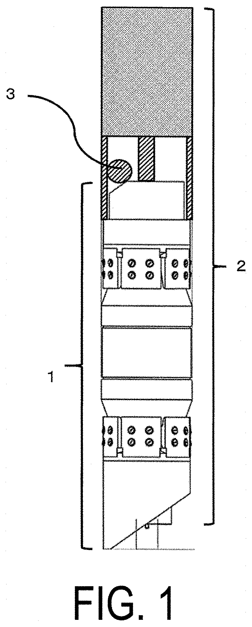
[0029] FIG. 1 is a diagram illustrating a specific example of a well plugging apparatus of the present invention.
[0030] FIG. 2 is a schematic front cross-sectional diagram illustrating a specific example of the well plugging apparatus of the present invention.
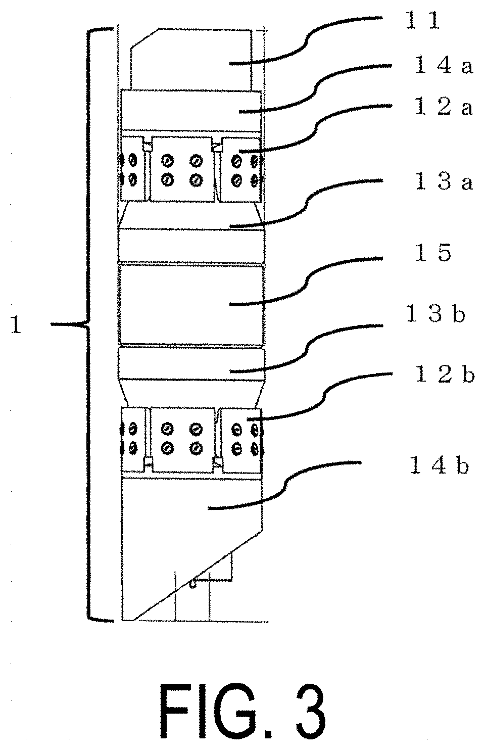
[0031] FIG. 3 is a diagram illustrating an appearance of a frac plug as a specific example of a downhole plug included in the well plugging apparatus of the present invention.
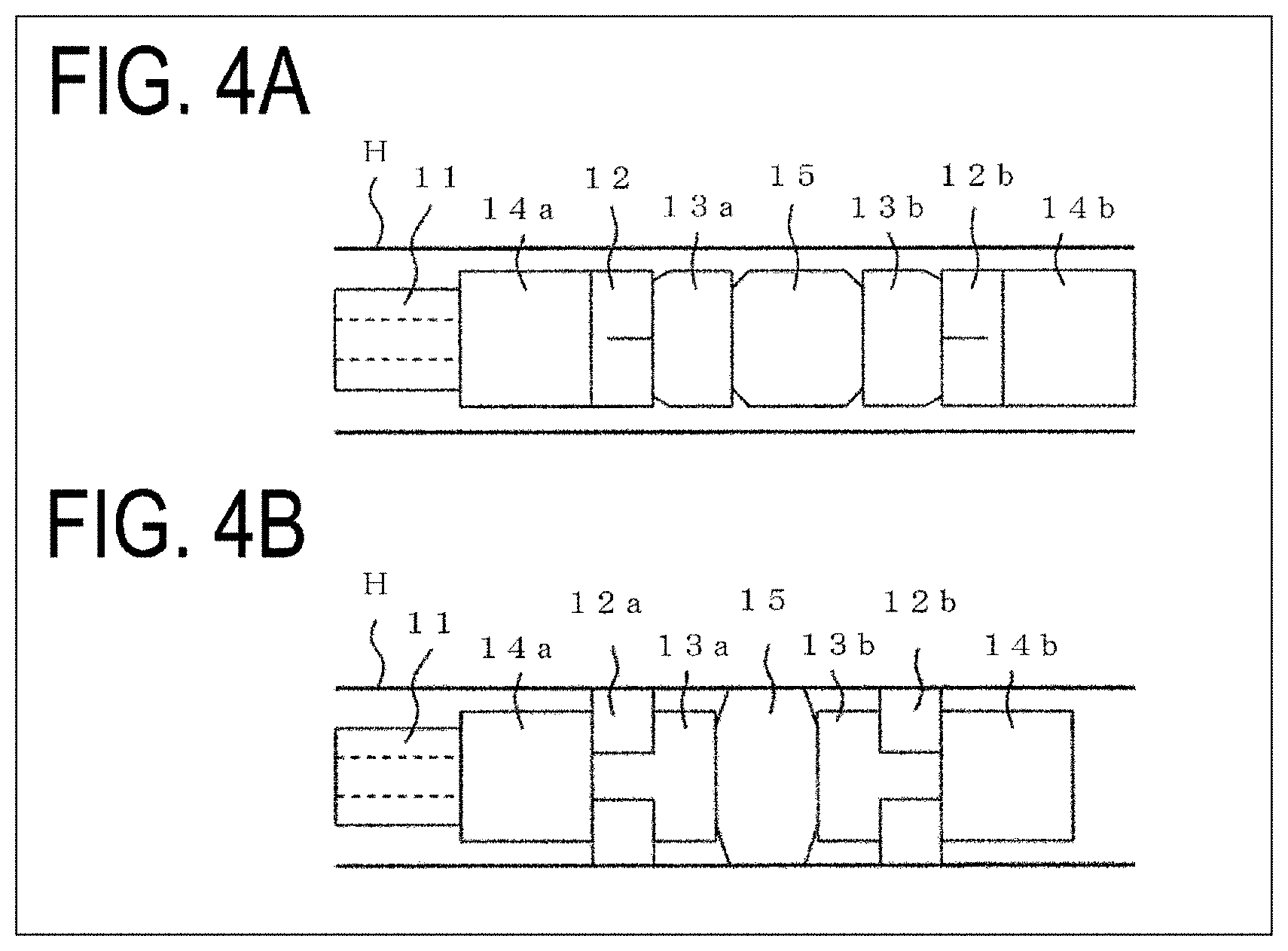
[0032] FIG. 4A is a schematic front cross-sectional diagram illustrating the frac plug as a specific example of the downhole plug included in the well plugging apparatus of the present invention, and FIG. 4B is a schematic front cross-sectional diagram illustrating a state where the downhole plug of FIG. 4A is installed and fixed in a wellbore.
[0033] FIG. 5A is a diagram illustrating a circumferential cross-section of a setting rod of FIG. 2 partially cut off into a straight line shape, FIG. 5B is a diagram illustrating a circumferential cross-section of the setting rod of FIG. 2 partially cut off into a curvilinear shape, and FIG. 5C and FIG. 5C' are diagrams illustrating circumferential cross-sections of the setting rods of FIG. 2 partially cut off into angular shapes.
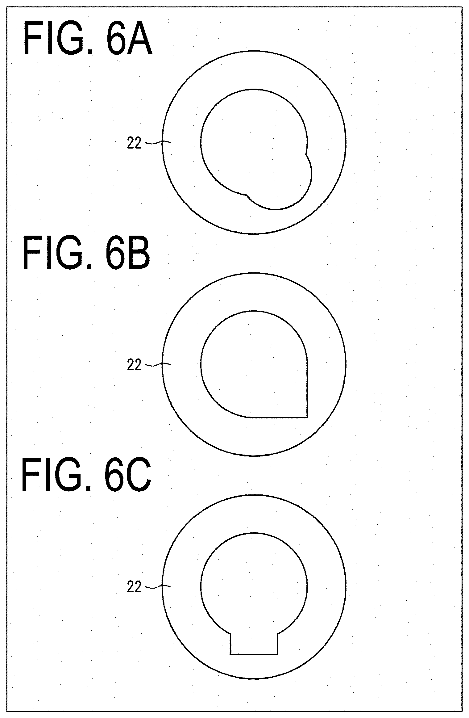
[0034] FIG. 6A is a diagram illustrating a circumferential cross-section of the setting sleeve of FIG. 2 with an inner surface having a curvilinear groove, and FIG. 6B and FIG. 6C are diagrams illustrating circumferential cross-sections of the setting sleeves of FIG. 2 with inner surfaces having angular grooves.
DESCRIPTION OF EMBODIMENTS
[0035] The present invention relates to a well plugging apparatus including a downhole plug, a setting tool for installing the downhole plug, and an obstacle to plug a flow path in the downhole plug and a method for temporarily plugging a well using the same. The following describes the well plugging apparatus and the plugging method according to one embodiment of the present invention.
1. Well Plugging Apparatus
[0036] The following describes the well plugging apparatus according to the present embodiment with reference to the drawings. The well plugging apparatus of the present embodiment includes a downhole plug 1, a setting tool 2, and an obstacle 3 to plug a flow path in the downhole plug. Note that FIG. 1 is a specific example of means to solve the problems of the present invention, and the scope of the present invention is not limited to the well plugging apparatus with the aspect illustrated in FIG. 1.
(1) Downhole Plug
[0037] The downhole plug, which is referred to as frac plug, bridge plug, packer, or the like, is a device installed into a wellbore to plug a part of the well. The downhole plug includes at least one mandrel and one or more members mounted on an outer peripheral surface orthogonal to an axial direction of the mandrel. The following describes the frac plug 1 in the aspect illustrated in FIG. 1 as one example of the downhole plug. FIG. 3 illustrates an appearance of the frac plug 1. As illustrated in FIG. 3, the frac plug 1 includes a mandrel 11 and members mounted on an outer peripheral surface orthogonal to an axial direction of the mandrel 11.
1) Mandrel
[0038] The mandrel 11 provided with the frac plug 1 is a member that has an approximately round shape in cross-section and has a length sufficiently long relative to a diameter of the cross-section to ensure strength of the frac plug 1. The diameter of the cross-section of the mandrel 11 is appropriately selected according to the size of the wellbore. This diameter configured slightly smaller than an inner diameter of the wellbore allows the frac plug 1 to move inside the wellbore. Meanwhile, the diameter of the mandrel 11 and the inner diameter of the wellbore have a difference in diameter to the extent that the wellbore can be plugged by expanding a diameter of a diameter-expandable, circular rubber member 15 described later and the like. While the mandrel 11 has the length, for example, approximately 5 to 20 times of the diameter of the cross-section, the length is not limited to this. The diameter of the cross-section of the mandrel 11 is typically in a range approximately from 5 to 30 cm.
[0039] Although the mandrel 11 may be a solid, from perspectives of securing the flow path at an early stage of fracturing, reduction in weight of the mandrel, and the like, the mandrel 11 is preferably a hollow mandrel at least partially including a hollow portion along the axial direction. That is, the hollow portion may be configured so as to penetrate the mandrel 11 along the axial direction or to not penetrate the mandrel 11 along the axial direction. In addition, to push the frac plug 1 into the well using a fluid for transportation, the mandrel 11 preferably has the hollow portion along the axial direction. When the mandrel 11 has the hollow portion along the axial direction, the cross-sectional shape of the mandrel 11 is a circular ring shape formed by two concentric circles defining the diameter (outer diameter) of the mandrel 11 and the outer diameter of the hollow portion (corresponding to the inner diameter of the mandrel 11). A ratio of the diameters of the two concentric circles, that is, the ratio of the outer diameter of the hollow portion to the diameter of the mandrel 11 is preferably at most 0.7. The magnitude of this ratio has a reciprocal relationship with the magnitude of a ratio of a thickness of the hollow mandrel 11 to the diameter of the mandrel 11, so determining the upper limit of this ratio can be considered equivalent to determining a preferable lower limit of the thickness of the hollow mandrel. When the thickness of the hollow mandrel is too thin, the strength (in particular, the tensile strength) of the hollow mandrel may be insufficient when the frac plug 1 is disposed inside the wellbore or at the time of plugging the wellbore or fracturing, which may damage the frac plug 1 in extreme cases. Therefore, the ratio of the outer diameter of the hollow portion to the diameter of the mandrel 11 is more preferably at most 0.6 and even more preferably at most 0.5.
[0040] The diameter of the mandrel 11 and the outer diameter of the hollow portion may be uniform along the axial direction of the mandrel 11, but may also vary along the axial direction. That is, by varying the outer diameter of the mandrel 11 along the axial direction, the outer peripheral surface of the mandrel 11 may include a bent part such as a convex portion, a step, a flange portion, a recess portion (groove portion), and further a screw portion (typically a male screw-thread structure), or meshing portions of a ratchet mechanism described later. In addition, the outer diameter of the hollow portion (inner diameter of the mandrel 11) may vary along the axial direction to provide a bent part, such as a convex portion, a step, a groove portion, and further a screw portion (a male screw-thread structure or a female screw-thread structure) in the inner peripheral surface of the mandrel 11. Further, the bent part can have a tapered portion.
[0041] Additionally, as described below, since the obstacle is disposed in a space (hereinafter, this space may also be referred to as "space inside the setting tool") formed by a setting sleeve inner wall, a setting rod, and a mandrel rear end in the well plugging apparatus of the present embodiment, the mandrel rear end may be cut out such that the obstacle can be disposed. The cutout preferably has a shape approximately identical to the surface shape of the obstacle.
[0042] The convex portion, step, flange portion, and recessed portion (groove portion), which can be provided in the outer peripheral surface or the inner peripheral surface of the mandrel 11, are usable as supporting parts when the frac plug 1 is transported in the well, or are usable as parts for mounting and fixation of another member to the outer peripheral surface or the inner peripheral surface of the mandrel 11. In addition, when the mandrel 11 has the hollow portion, the part can serve as a seat to hold the obstacle to plug the flow path. In a case where the hollow portion of the mandrel 11 is present at least in the rear end, the mandrel 11 is open. Configuring this opening into a seat having the shape configured to hold the obstacle allows the obstacle to be seated more reliably and plugging the flow path more reliably as a result. Note that, as the seat, in addition to configuring the opening of the mandrel 11 into the seat shape, a seat member having an open center part may be attached to the mandrel 11. For example, in the use of a ball as the obstacle, appropriately selecting the size of the opening in the seat (ball seat) of the downhole plug prevents cracking and escape of the ball, thereby ensuring plugging the flow path more reliably. Furthermore, the ring-shaped ratchet mechanism orthogonal to the axial direction of the mandrel may be configured in the outer peripheral surface of the mandrel 11. In cooperation with an inner peripheral surface of a member mounted on the outer peripheral surface orthogonal to the axial direction of the mandrel 11, the ratchet mechanism permits one-way movement of this member along the axial direction of the mandrel and forms the plurality of meshing portions restricting a movement in the opposite direction.
Material Forming Mandrel
[0043] The material forming the mandrel 11 provided in the downhole plug is not particularly limited. Materials conventionally used as materials to form a mandrel provided with a downhole plug are usable. Examples of the material can include a metal material (aluminum, steel, stainless steel, and the like), fiber, wood, a composite material, resin, and the like. Specifically, the material can include a composite material containing a reinforcing material such as carbon fiber, particularly a composite material containing polymer such as epoxy resin and phenol resin, and the like. Since the downhole plug of the present embodiment allows cost reduction and shortening of the process for well drilling through ease of removal of the downhole plug and securing the flow path, the mandrel 11 is preferably made of a degradable material.
Degradable Material
[0044] In the mandrel 11 made of the degradable material in the downhole plug used for the present embodiment, as the degradable material, a degradable material having biodegradability or hydrolyzability, and further a degradable material that can be chemically degraded by any other method are usable.
[0045] Note that a material physically degraded by applying a large mechanical force, such as destruction and disintegration, like a metal material such as aluminum, which is generally used as the mandrel provided in the downhole plug conventionally, is not applied as the degradable material forming the mandrel 11 provided in the downhole plug. However, as seen in a composite material of degradable resin and a metal material or an inorganic substance, a material that reduces strength possessed by the original resin due to reduction in degree of polymerization and the like and embrittles, and as a result, is easily disintegrated and loses its shape by an application of an extremely small mechanical force is classified as the degradable material. Specifically, the degradable material configured as follows is included. A recess portion such as a depression having a predetermined shape is provided in a base material made of a degradable material such as degradable resin including polyglycolic acid (hereinafter also sometimes referred to as "PGA"), metal (such as a metal piece) or an inorganic substance having a shape matching with the shape of this recess portion is fitted, and these members are fixed with an adhesive. Alternatively, a wire, fiber, or the like is wound around to be fixed such that the metal piece or the inorganic material and the base material can maintain the fixed state.
[0046] In the downhole plug used in the present embodiment, in the case of the mandrel 11 made of the degradable material, the degradable material is preferably a hydrolyzable material degraded with water at a predetermined temperature or more. Preferably, the degradable material mainly contains PGA. Among PGAs, polyglycolic acid having a weight average molecular weight of 150000 or greater is preferable, and high molecular weight polyglycolic acid having a weight average molecular weight of 180000 or greater is especially preferable because of its high strength. That is, a downhole plug with the mandrel 11 made of PGA with high molecular weight is desirable. Furthermore, the degradable material may contain a reinforcing material or can contain another ingredient. Degradable metal is also usable as the degradable material forming the mandrel 11. Because of having high strength, Mg alloy is preferable as the degradable metal used for the mandrel 11.
2) Members Mounted on Outer Peripheral Surface Orthogonal to Axial Direction of Mandrel
[0047] The downhole plug used in the present embodiment includes the mandrel and the members mounted on the outer peripheral surface orthogonal to the axial direction of the mandrel. That is, in the downhole plug, for efficiently and reliably performing the transport and installation of this plug, plugging of the wellbore, and fracturing, various members are typically mounted on the outer peripheral surface of the mandrel additionally for the purpose of improving ease of handling and the like. The members mounted on the outer peripheral surface orthogonal to the axial direction of the mandrel are not particularly limited as long as the members are conventionally used in the downhole plug. In particular, as illustrated in FIG. 3, regarding the frac plug 1, at least one of members selected from a group of a slip 12, a wedge 13, a pair of ring-shaped fixing members 14, and the diameter expandable circular rubber member 15 is preferable. Note that these members are referred to as members in the meaning including mounting members for mounting of the respective members to the mandrel.
Material Forming Member Mounted on Outer Peripheral Surface Orthogonal to Axial Direction of Mandrel
[0048] The material forming the member mounted on the outer peripheral surface of the mandrel used in the present embodiment is not particularly limited, and a material conventionally used as a material forming this member provided in the downhole plug is usable. Examples of the material can include a metal material (aluminum, steel, stainless steel, and the like), fiber, wood, a composite material, resin, and the like. Specifically, the material can include a composite material containing a reinforcing material such as carbon fiber, particularly a composite material containing polymer such as epoxy resin and phenol resin, and the like. From a perspective that the cost reduction and the shortening of process for well drilling can be achieved through ease of release of the plugging and securing of the flow path after use, at least one of the members is preferably made of a degradable material, similarly as previously described regarding the mandrel.
Degradable Material
[0049] In the downhole plug used in the present embodiment, as the degradable material forming at least one of the members, similarly as previously described regarding the mandrel, the degradable material having biodegradability or hydrolyzability, additionally a degradable material that can be chemically degraded by any other method, and a degradable material that can be embrittled and easily disintegrated are usable. With the member being a diameter expandable circular rubber member, as the degradable material, for example, degradable rubber such as aliphatic polyester-based rubber, polyurethane rubber, natural rubber, polyisoprene, acrylic rubber, aliphatic polyester rubber, polyester-based thermoplastic elastomer, and polyamide-based thermoplastic elastomer are usable.
3) Operating and Installing Downhole Plug and Plugging Wellbore
[0050] The downhole plug used in the present embodiment is operated by the setting tool described later and installed in the wellbore. For example, in the frac plug 1, an application of a force that reduces a distance between the pair of ring-shaped fixing members 14 in the axial direction of the mandrel causes the slip 12 to climb on an inclined top surface of the wedge 13 and to move outward orthogonal to the axial direction of the mandrel. Then, the outermost circumferential surface of this slip 12 orthogonal to the axial direction of the mandrel abuts on the inner wall of the wellbore, and thus the plug can be installed at a predetermined position in the wellbore. Additionally, in association with the diameter expandable circular rubber member 15 being compressed in the axial direction of the mandrel to decrease the axial distance (decrease in diameter), the diameter expandable circular rubber member 15 expands in diameter in the direction orthogonal to the axial direction of the mandrel. This circular rubber member 15 expands in diameter and the outward portion in the direction orthogonal to the axial direction abuts on the inner wall of the wellbore and further the inward portion in the direction orthogonal to the axial direction abuts on the outer peripheral surface of the mandrel, thereby ensuring plugging (sealing) the space between the plug 1 and the wellbore (plugging of wellbore). Then, in the state where the space between the plug and the wellbore has been plugged (sealed), fracturing can be performed.
(2) Setting Tool
[0051] The setting tool used in the well plugging apparatus of the present embodiment has an approximately columnar shape and includes the setting rod and the setting sleeve. The setting rod typically has a rod shape and is centered in a cross-section of the setting tool (cross-section parallel to the bottom surface of the approximate column). That is, the setting rod is inserted into the hollow portion of the setting tool. The setting sleeve has a tubular shape surrounding one end of a long shaft of the setting rod.
[0052] The setting tool itself or a part of the setting tool of the present embodiment is sometimes referred to as an adapter kit, and the adapter kit includes a setting rod and a setting sleeve.
[0053] The setting tool used in the present embodiment is disposed from the rear with respect to the rear end of the downhole plug to the rear end side in the hollow portion, and the setting rod and the setting tool are each in contact with the downhole plug. That is, the setting rod is directly or indirectly connected to the mandrel, and the setting sleeve is installed adjacent to the member mounted on the outer peripheral surface orthogonal to the axial direction of the mandrel. When the setting tool is operated, while the setting sleeve suppresses the movement of the member mounted on the outer peripheral surface of the mandrel in the rear end direction, the setting rod moves in the rear end direction and transmits the force in the rear end direction to the mandrel to pull out the mandrel in the rear end direction, and the downhole plug operates as described above. An example includes a setting tool that includes a setting sleeve and a setting rod operated by gas generated by explosion.
1) Setting Rod
[0054] In the well plugging apparatus of the present embodiment, while the setting rod is connected to the mandrel, the setting rod is typically directly or indirectly connected to the mandrel at the end portion on the side opposite to the end portion surrounded by the setting sleeve. The setting rod is inserted into the hollow portion of the mandrel from the opening at the rear of the mandrel. Although the connecting position of the mandrel with the setting rod may be the rear end side, the center, or the front end side of the mandrel in the longitudinal axial direction, in a case where compressive strength is insufficient due to the mandrel made of resin or the like, the setting rod is preferably connected to the front end side of the mandrel. In this case, the setting rod is connected to the front end side from the rear end side of the mandrel through the hollow portion. The following describes an example of connecting the setting rod to the front end of the mandrel with reference to FIG. 2 and FIG. 3.
[0055] A setting rod 21 in FIG. 2 is connected to the downhole plug 1 with a connection portion 23. A method for connecting the connection portion 23 includes a method for directly connecting and fixing the connection portion 23 to the front end of the mandrel 11 and a method for indirectly connecting and fixing the connection portion 23 via a connection member (not illustrated) installed on the front end of the mandrel 11 and installed on the mandrel 11. A method for fixing the connection portion 23 to the downhole plug 1 includes a method for fixing the connection portion 23 to the downhole plug 1 using a screw engraved on the outer periphery of the connection portion 23 and a method for fixing the connection portion 23 with a pin. The screw and the pin are preferably damaged due to a force applied in the axial direction of the mandrel to disconnect the downhole plug and the setting tool.
[0056] As described later, in the well plugging apparatus of the present embodiment, the obstacle is disposed in a space formed by the setting sleeve inner wall, the setting rod, and the mandrel rear end or the member mounted on the rear end. Accordingly, the setting rod may be deformed by, for example, recessing, bending, or shaving a part of the rod into a sector shape in the axial direction such that the setting sleeve can internally include the obstacle (ball). In other words, the setting rod may have a groove or a notch structure to the axial direction.
[0057] Specific examples of the deformation of the setting rod include: a part of a round shape as a cross-section of the setting rod being cut off into a straight line shape (FIG. 5A), cut off into a curvilinear shape (FIG. 5B), cut off into angular shapes (FIGS. 5C and 5C'), or the like.
[0058] Although a position and a length of the deformation in the entire length of the setting rod are not particularly limited as long as the function of the setting rod is not inhibited, the deformed parts illustrated in FIGS. 5A to 5C' are preferably on the front end side in the length from the distal end (front end) of the setting rod not connected to the downhole plug to the rear end of the downhole plug. Additionally, the length of the deformed part is preferably 10 mm or more in the axial direction of the setting rod.
2) Setting Sleeve
[0059] A setting sleeve 22 of the present embodiment is positioned adjacent to the rear end side of the member mounted on the outer peripheral surface of the mandrel 11, and has a function of suppressing the movement of the member on the outer peripheral surface of the mandrel to the rear side.
[0060] In addition, similarly to the setting rod, the setting sleeve may have a groove or a notch structure in the inner wall such that the setting sleeve can internally include the obstacle (ball). Specific examples of the groove in the setting sleeve inner wall include a curvilinear groove (FIG. 6A) or angular grooves (FIGS. 5B and 6C) in the cross-section of the setting sleeve.
[0061] The groove in the setting sleeve inner wall only needs to have a shape that the setting sleeve can internally include the obstacle and the position, the length, and the depth are not particularly limited. However, the grooves illustrated in FIGS. 6A to 6C preferably have a length (in the axial direction of the setting sleeve) of 10 mm or greater, a width of 5 mm or greater, and a depth of 1 mm or greater.
Material Forming Setting Tool
[0062] The material forming the setting tool used in the present embodiment is not particularly limited, and conventionally used materials are usable.
(3) Obstacle for Plugging Flow Path in Downhole Plug
[0063] The obstacle for plugging the flow path in the downhole plug used in the present embodiment is disposed in the space formed by the setting sleeve inner wall and the setting rod of the setting tool, and the mandrel rear end or the member mounted on the rear end. The obstacle for plugging the flow path in the downhole plug has a function to plug the flow path in the downhole plug after the downhole plug is installed in the well and the setting rod is removed. As long as the flow path in the downhole plug can be plugged and the obstacle has the size and the shape that can be fallen into the space in the above-described setting tool, the shape of the obstacle is not particularly limited and, for example, includes shapes such as a ball, a dart, or a disk. Among these obstacles, the ball can plug the opening of the seat regardless of the seated direction and the flow path can be plugged reliably and therefore is preferable.
Material Forming Obstacle to Plug Flow Path in Downhole Plug
[0064] The material forming the obstacle to plug the flow path in the downhole plug used in the present embodiment is not particularly limited, and materials conventionally used as materials forming this obstacle are usable. Examples of the material can include a metal material (aluminum, steel, stainless steel, or the like), fiber, wood, a composite material, resin, and the like. Specifically, the materials can include a composite material containing a reinforcing material such as carbon fiber, and particularly a composite material containing polymer such as epoxy resin and phenol resin, and the like. From a perspective that the cost reduction and the shortening of process for well drilling can be achieved through ease of release of the plugging and securing of the flow path after the use of the downhole plug, at least a part of the obstacle is preferably made of a degradable material, similarly as previously described regarding the mandrel. The degradable material mainly containing PGA is more preferred. In a case of the use of PGA as the main component, the weight average molecular weight of PGA is preferably large from a perspective of increasing strength, for example, 50000 or greater is preferable, 100000 or greater is more preferable, and 150000 or greater is further preferable.
Degradable Material
[0065] As the degradable material forming the obstacle to plug the flow path in the downhole plug used in the present embodiment, similarly as previously described regarding the mandrel, the degradable material having biodegradability or hydrolyzability, additionally a degradable material that can be chemically degraded by any other method, and a degradable material that can be embrittled and easily disintegrated are usable. Among the materials, degradable resin or degradable metal features ease of adjustment of a degradation rate, and thus is preferable as the degradable material used for the obstacle. In particular, because of its high strength, polyglycolic acid is preferable as the degradable resin, and Mg alloy is preferable as the degradable metal.
[0066] With the well plugging apparatus of the above-described present embodiment, the obstacle to plug the flow path in the downhole plug can be reliably supplied in a short time. Thus, damage in the obstacle accompanied by the transport of the obstacle can be avoided and a fluid volume to transport the obstacle can be saved. This allows reducing the cost for well drilling and allows shortening the process for well drilling.
2. Method for Plugging Well
[0067] The well plugging apparatus of the present embodiment is usable regardless of the depth of the well and whether a vertical hole or a horizontal hole.
[0068] The method for plugging the well using the well plugging apparatus of the present embodiment is as follows. First, the well plugging apparatus of the present embodiment is moved to any position inside the well using a fluid or the like (FIG. 4A). After that, when the setting tool is operated, the annular rubber member and the slip are expanded in diameters to install and fix the downhole plug to the inner wall of the wellbore (FIG. 4B). Then, the setting tool and the downhole plug are disconnected, and the setting rod is removed from the hollow portion of the mandrel. The obstacle internally included in the setting sleeve is supplied and disposed at a position to plug the flow path in the downhole plug, for example, the seat installed in the mandrel, thus completing the plugging.
[0069] When the obstacle is made of, for example, the degradable material having hydrolyzability, exposure of the obstacle under water for a predetermined period degrades the obstacle, and disintegrating, dissolving, or exiting the obstacle from the opening of the seat (receptacle) allows recovering the plugged flow path.
3. Summary
[0070] A well plugging apparatus for plugging a well that includes a downhole plug, a setting tool, and one or more obstacles. The setting tool is disposed on a rear end side of the downhole plug. The setting tool operates and installs the downhole plug. The one or more obstacles plug a flow path in the downhole plug. The downhole plug includes a hollow mandrel that opens at least in a rear end. The setting tool includes a setting rod directly or indirectly connected to a front end side of the mandrel and a setting sleeve disposed to cover at least a part of the setting rod and at least a part of the downhole plug. The setting rod is inserted from the opening in the rear end of the mandrel into the hollow portion of the mandrel. The obstacle is internally included in a space inside the setting tool.
[0071] Additionally, preferably the mandrel contains a resin as a main component.
[0072] Additionally, preferably the mandrel contains a degradable metal as a main component.
[0073] Additionally, preferably the mandrel contains a degradable resin as a main component.
[0074] Additionally, preferably the downhole plug includes a seat that receives the obstacle.
[0075] Additionally, preferably the obstacle is a ball, a dart, or a disk.
[0076] Additionally, preferably the obstacle at least partially contains a degradable material.
[0077] Additionally, preferably the degradable material is a degradable resin or a degradable metal.
[0078] Additionally, preferably the mandrel has a rear end having a notch structure configured to internally include the obstacle in a space inside the setting tool.
[0079] Additionally, preferably at least one of the setting rod or the setting sleeve has a groove or a notch structure with respect to an axial direction configured to internally include the obstacle in a space inside the setting tool.
[0080] Preferably at least one of the setting rod or the setting sleeve has the sector-shaped notch structure with respect to the axial direction configured to internally include the obstacle in the space inside the setting tool.
[0081] Additionally, the setting rod has the groove or the notch structure with respect to the axial direction.
[0082] Additionally, preferably the setting sleeve has a groove in an inner surface.
[0083] There is provided a method for temporarily plugging a well using a well plugging apparatus including a downhole plug, a setting tool, and one or more obstacles. The setting tool is disposed on a rear end side of the downhole plug. The setting tool operates and installs the downhole plug. The one or more obstacles plug a flow path in the downhole plug. The downhole plug includes a hollow mandrel at least opening in a rear end. The setting tool includes a setting rod directly or indirectly connected to a front end side of the mandrel and a setting sleeve having a shape to cover at least a part of the setting rod and at least a part of the downhole plug. The setting rod is inserted from the opening in the rear end of the mandrel into the hollow portion of the mandrel. The obstacle is internally included in a space inside the setting tool. The method includes the following steps a) to d): a) moving the well plugging apparatus to any position in the well and operating and installing the downhole plug; b) disconnecting the setting tool and the downhole plug to pull out the setting rod; c) moving the obstacle in the setting tool to plug the flow path in the hollow portion of the mandrel; and d) after an elapse of a predetermined period, removing the obstacle to recover the flow path.
INDUSTRIAL APPLICABILITY
[0084] The present invention is the well plugging apparatus including the setting tool and the downhole plug that causes the obstacle to plug the flow path in the downhole plug to be internally included in the setting tool adjacent to the downhole plug. Accordingly, the well plugging apparatus that can supply the obstacle to the downhole plug in a short time and safely, avoid damage in the obstacle, reduce the cost for well drilling including saving of a fluid volume for transporting the obstacle, and shorten the process is provided, bringing a high industrial applicability. Additionally, the method for temporarily plugging the well using the well plugging apparatus is provided, bringing a high industrial applicability.
REFERENCE SIGNS LIST
[0085] 1 Frack plug [0086] 2 Setting tool [0087] 3 Ball [0088] 12a, 12b Slip [0089] 13a, 13b Wedge [0090] 14a, 14b Ring-shaped fixing member [0091] 15 Diameter expandable circular rubber member [0092] 21 Setting rod [0093] 22 Setting sleeve [0094] 23 Connecting portion between setting tool and frac plug [0095] H Inner wall of wellbore
* * * * *
D00000
D00001
D00002
D00003
D00004
D00005
D00006
XML
uspto.report is an independent third-party trademark research tool that is not affiliated, endorsed, or sponsored by the United States Patent and Trademark Office (USPTO) or any other governmental organization. The information provided by uspto.report is based on publicly available data at the time of writing and is intended for informational purposes only.
While we strive to provide accurate and up-to-date information, we do not guarantee the accuracy, completeness, reliability, or suitability of the information displayed on this site. The use of this site is at your own risk. Any reliance you place on such information is therefore strictly at your own risk.
All official trademark data, including owner information, should be verified by visiting the official USPTO website at www.uspto.gov. This site is not intended to replace professional legal advice and should not be used as a substitute for consulting with a legal professional who is knowledgeable about trademark law.