Razor Mesh Panel
COCHRANE; Richard Bruce
U.S. patent application number 16/682193 was filed with the patent office on 2020-05-14 for razor mesh panel. The applicant listed for this patent is COCHRANE STEEL PRODUCTS (PTY) LTD. Invention is credited to Richard Bruce COCHRANE.
| Application Number | 20200149308 16/682193 |
| Document ID | / |
| Family ID | 70551040 |
| Filed Date | 2020-05-14 |

| United States Patent Application | 20200149308 |
| Kind Code | A1 |
| COCHRANE; Richard Bruce | May 14, 2020 |
RAZOR MESH PANEL
Abstract
Disclosed is a fence panel including a rectangular mesh body which includes a plurality of lengths of razor wire arranged to form a plurality of diamond-shaped mesh apertures, each aperture having a major axis of length L and a minor axis of length L/2, and wherein the lengths of razor wire are fixed to one another at respective junctions, wherein L.ltoreq.200 mm.
| Inventors: | COCHRANE; Richard Bruce; (Kempton Park, ZA) | ||||||||||
| Applicant: |
|
||||||||||
|---|---|---|---|---|---|---|---|---|---|---|---|
| Family ID: | 70551040 | ||||||||||
| Appl. No.: | 16/682193 | ||||||||||
| Filed: | November 13, 2019 |
| Current U.S. Class: | 1/1 |
| Current CPC Class: | E04H 17/04 20130101 |
| International Class: | E04H 17/04 20060101 E04H017/04 |
Foreign Application Data
| Date | Code | Application Number |
|---|---|---|
| Nov 13, 2018 | ZA | 2018/07605 |
Claims
1. A fence panel which comprises a rectangular mesh body with first and second opposed parallel edges, and third and fourth opposed parallel edges, wherein the body comprises a plurality of lengths of razor wire arranged to form a plurality of diamond-shaped mesh apertures, each aperture having a major axis of length L and a minor axis of length L/2, wherein the lengths of razor wire are fixed to one another at respective junctions, and wherein the junctions which are closest to the first edge are spaced apart from one another and located on a line which is parallel to and spaced from the first edge by a distance D, and wherein D.ltoreq.0.25 L and L.ltoreq.200 mm.
2. A fence panel according to claim 1 wherein the body comprises a first array of a first plurality of elongate parallel and spaced apart first lengths of razor wire and a second array of a second plurality of elongate parallel and spaced apart second lengths of razor wire, wherein the first array transversely overlies the second array thereby forming a plurality of diamond-shaped mesh apertures, each aperture having a major axis of length L and a minor axis of length L/2, the first lengths being respectively fixed to the second lengths at each junction at which a first length overlies and contacts a second length.
3. A fence panel according to claim 1 wherein L=200 mm.
4. A fence panel according to claim 1 wherein L/2=100 mm.
5. A fence panel according to claim 1 wherein D.ltoreq.40 mm.
6. A fence panel according to claim 1 wherein, in use of the panel, the mesh body is positioned with the first edge uppermost and horizontal, and with the major axis of each mesh aperture extending vertically.
7. A fence panel according to claim 2 wherein L=200 mm.
8. A fence panel according to claim 2 wherein L/2=100 mm.
9. A fence panel according to claim 2 wherein D.ltoreq.40 mm.
10. A fence panel according to claim 2 wherein, in use of the panel, the mesh body is positioned with the first edge uppermost and horizontal, and with the major axis of each mesh aperture extending vertically.
Description
BACKGROUND OF THE INVENTION
[0001] This invention relates to a fence panel which is formed from razor wire.
[0002] A razor mesh fence panel is formed by welding together, at respective points of contact, two arrays of transversely disposed and parallel lengths of razor wire which are positioned to form diamond-shaped mesh apertures. To a considerable extent, in some markets, the mesh panels have been standardized in that each aperture has a major axis with a length of the order of 300 mm and a minor axis with a length of the order of 150 mm.
[0003] Edges of the mesh panel are defined by relatively short ends of the razor wires which project from adjacent welding points. It has been found that, at the time of manufacture, the mesh panel, along its edges, has a regular and acceptable appearance. However, due to forces which are exerted during storage, transport and erection of the fence panels, it frequently occurs that the projecting ends, at the edges of a panel, are easily bent. The deformation of the razor wires at the edges of the panel detract from the appearance of an erected fence. To address this drawback a stiffening component is attached to the edges of the panel. For example, strip material has been welded to the projecting ends of the razor wire. This remedial action can however be cumbersome to undertake and adds unnecessarily to the cost of the final product.
[0004] A mesh panel with an aperture of this size does present a formidable deterrent but, nonetheless, the panel can be scaled by a person with adequate protection who can place a foot into each diamond mesh aperture and thereby climb over the panel. The deterrent effect can be improved if two of the panels are used with a first panel superimposed over a second panel but being displaced in a lateral sense so that effectively the wires in one panel divide each mesh aperture in the adjacent panel into four smaller, diamond-shaped apertures. The resulting combination of panels is however expensive and heavy and difficult to handle. Apart therefrom the projecting ends of the razor wire exhibit the drawback referred to.
[0005] An object of the present invention is to provide a fence panel which, at least to some extent, addresses the aforementioned factors.
SUMMARY OF INVENTION
[0006] The applicant has found that, surprisingly, the tendency of the razor wires at the edges of the panel, to be deformed during transport, erection etc can be prevented, to a substantial extent, if the size of each mesh aperture is reduced. To achieve this the invention provides a fence panel which comprises a rectangular mesh body with first and second opposed parallel edges, and third and fourth opposed parallel edges, wherein the body comprises a plurality of lengths of razor wire arranged to form a plurality of diamond-shaped mesh apertures, each aperture having a major axis of length L and a minor axis of length L/2, wherein the lengths of razor wire are fixed to one another at respective junctions, and wherein the junctions which are closest to the first edge are spaced apart from one another and located on a line which is parallel to and spaced from the first edge by a distance D, and wherein D.ltoreq.0.25 L and L.ltoreq.200 mm.
[0007] The body of the fence panel may comprise a first array of a first plurality of elongate parallel and spaced apart first lengths of razor wire and a second array of a second plurality of elongate parallel and spaced apart second lengths of razor wire, wherein the first array transversely overlies the second array thereby forming a plurality of diamond-shaped mesh apertures, each aperture having a major axis of length L and a minor axis of length L/2, the first lengths being respectively fixed to the second lengths at each junction at which a first length overlies and contacts a second length.
[0008] Preferably L=200 mm. Thus L/2=100 mm.
[0009] Preferably D.ltoreq.0.2.times.L, i.e. D.ltoreq.40 mm.
[0010] In use of the panel the mesh body is preferably positioned with the first edge uppermost and horizontal, and with the major axis of each mesh aperture extending vertically.
BRIEF DESCRIPTION OF THE DRAWINGS
[0011] The invention is further described by way of example with reference to the accompanying drawings in which:
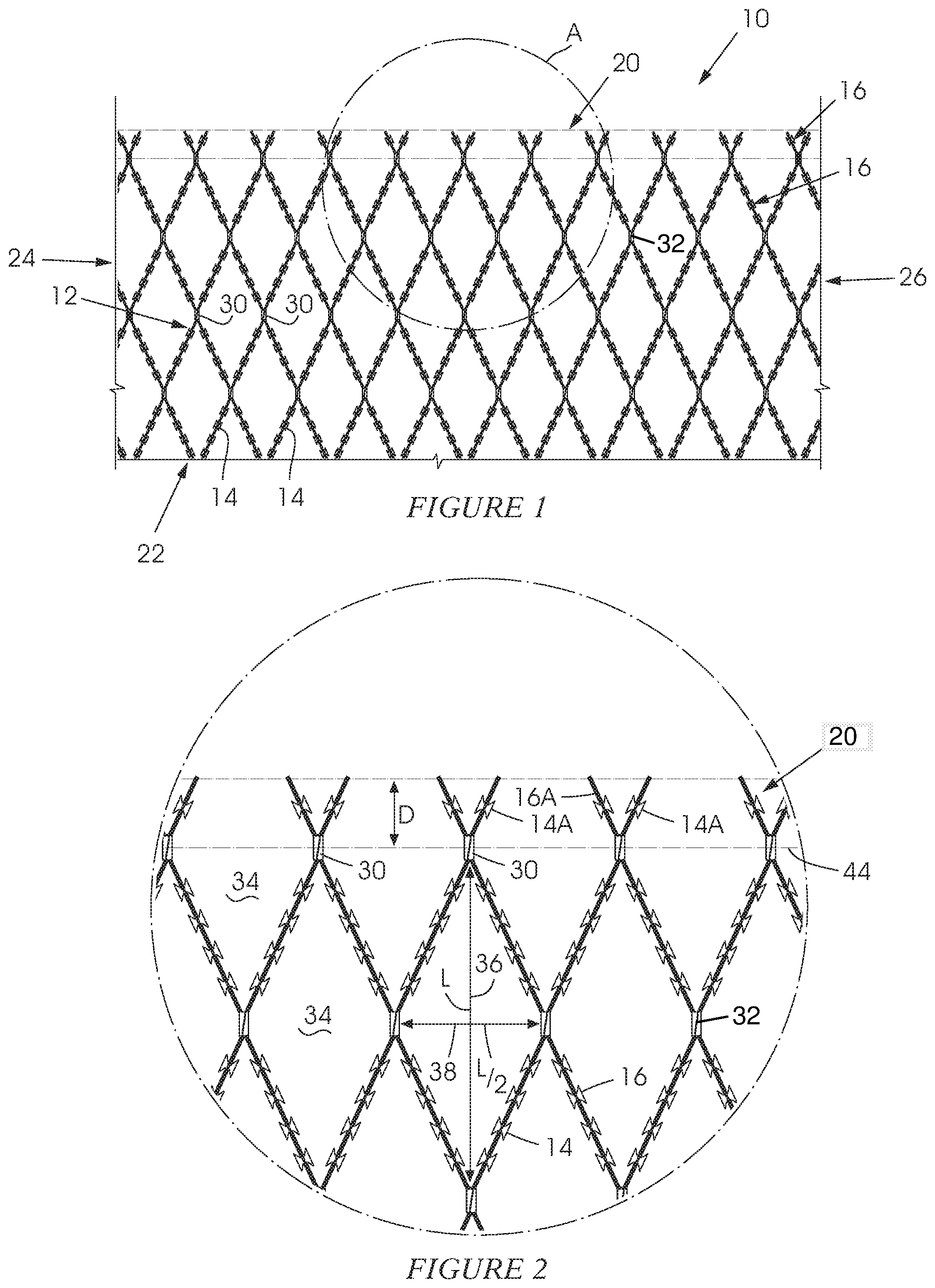
[0012] FIG. 1 shows a fence panel according to the invention which is made from a plurality of lengths of razor wire fixed together; and
[0013] FIG. 2 illustrates a portion of the fence panel in FIG. 1, on a larger scale than what is shown in FIG. 1.
DESCRIPTION OF PREFERRED EMBODIMENT
[0014] FIG. 1 of the accompanying drawings illustrates a fence panel 10 according to the invention. The panel 10 comprises a rectangular body 12 formed from transverse lengths 14 and 16 of razor wire arranged to form a diamond mesh configuration. The body 12 has opposed first and second parallel edges 20 and 22 respectively and opposed third and fourth parallel edges 24 and 26 respectively. The edges 24 and 26 are at a right angle to the edges 20 and 22.
[0015] The lengths 14 of razor wire are parallel to and are equally spaced apart from one another, and are arranged in a first array. The lengths 16 of razor wire are parallel to and are equally spaced apart from one another and are in a second array extending transversely to the first array. At junctions 30 at which the lengths 16 overlie and are in contact with the lengths 14, the wires are fixed together. The drawings illustrate that, in this respect, clips 32 are used to secure adjacent lengths of wire together. It is also possible though to weld the wires together at the respective points of intersection.
[0016] FIG. 2 is a view on an enlarged scale of a portion of the razor mesh panel shown in FIG. 1 enclosed in a circle marked A. The razor wire lengths 14 and 16 form diamond-shaped mesh apertures 34 each of which has a major axis 36 of length L and a minor axis 38 of length L/2. FIG. 2 shows the first edge 20 and those junctions 30 at which the contacting razor wire lengths 16 and 14 are secured together and which are closest to the first edge 20. These junctions are on a line 44 (shown as a dotted line) which is parallel to, and spaced from, the edge 20 by a distance D between the first edge 20 and the junction line 44. The lengths 14 and 16 have respective projecting portions 14A and 16A.
[0017] In the "standardized" razor mesh panel referred to hereinbefore L is of the order of 300 mm. Thus L/2, i.e. the minor axis 38, is of the order of 150 mm. What the applicant has found is that if L is reduced to 200 mm, i.e. the diamond aperture 34 has a major axis 36 of 200 mm and a minor axis 38 of 100 mm, the deterrent effect of the fence panel is significantly enhanced but, almost of equal importance, is the fact that with D.ltoreq.0.25 L i.e. .ltoreq.50 mm there is a reduced tendency for the projecting portions 14A and 16A of the razor wires adjacent the first edge 20 to be deformed or bent during handling or erection of a fence panel. Thus in a preferred embodiment L=200 mm, L/2=100 mm and D is of the order of 40 mm.
[0018] The enhanced deterrent effect does however require more razor wire to be included in the panel than in the standardized panel, referred to hereinbefore, but far less razor wire is used than if two standardized panels were to be fixed together.
* * * * *
D00000
D00001
XML
uspto.report is an independent third-party trademark research tool that is not affiliated, endorsed, or sponsored by the United States Patent and Trademark Office (USPTO) or any other governmental organization. The information provided by uspto.report is based on publicly available data at the time of writing and is intended for informational purposes only.
While we strive to provide accurate and up-to-date information, we do not guarantee the accuracy, completeness, reliability, or suitability of the information displayed on this site. The use of this site is at your own risk. Any reliance you place on such information is therefore strictly at your own risk.
All official trademark data, including owner information, should be verified by visiting the official USPTO website at www.uspto.gov. This site is not intended to replace professional legal advice and should not be used as a substitute for consulting with a legal professional who is knowledgeable about trademark law.