Architectual Climbing System With Improved Structural Stability
LEE; Myong Lae ; et al.
U.S. patent application number 16/603422 was filed with the patent office on 2020-05-14 for architectual climbing system with improved structural stability. The applicant listed for this patent is Myong Lae LEE LEE. Invention is credited to Chang Hun LEE, Chang Min LEE, Myong Lae LEE.
| Application Number | 20200149301 16/603422 |
| Document ID | / |
| Family ID | 60383158 |
| Filed Date | 2020-05-14 |


View All Diagrams
| United States Patent Application | 20200149301 |
| Kind Code | A1 |
| LEE; Myong Lae ; et al. | May 14, 2020 |
ARCHITECTUAL CLIMBING SYSTEM WITH IMPROVED STRUCTURAL STABILITY
Abstract
The present invention relates to a construction climbing system with improved structural stability and, more specifically, to a construction climbing system with improved structural stability, and having an improved form, the system being capable of more stably operating the attachment and detachment of a gang form provided in the climbing system without shaking, enabling the vertical movement of the climbing system to be smooth without stopping so as to ensure structural stability, and enabling a working space of an operator to be ensured as wide as possible by using an auxiliary extension platform, thereby enabling work stability of the operator to be improved.
| Inventors: | LEE; Myong Lae; (Incheon, KR) ; LEE; Chang Hun; (Incheon, KR) ; LEE; Chang Min; (Incheon, KR) | ||||||||||
| Applicant: |
|
||||||||||
|---|---|---|---|---|---|---|---|---|---|---|---|
| Family ID: | 60383158 | ||||||||||
| Appl. No.: | 16/603422 | ||||||||||
| Filed: | April 8, 2018 | ||||||||||
| PCT Filed: | April 8, 2018 | ||||||||||
| PCT NO: | PCT/KR2018/004108 | ||||||||||
| 371 Date: | October 7, 2019 |
| Current U.S. Class: | 1/1 |
| Current CPC Class: | E04G 21/3247 20130101; E04G 7/02 20130101; E04G 11/28 20130101; E04G 2003/286 20130101; E04G 3/28 20130101 |
| International Class: | E04G 11/28 20060101 E04G011/28; E04G 3/28 20060101 E04G003/28; E04G 7/02 20060101 E04G007/02 |
Foreign Application Data
| Date | Code | Application Number |
|---|---|---|
| Apr 11, 2017 | KR | 10-2017-0046672 |
Claims
1. A construction climbing system with improved structural stability, the construction climbing system comprising a cage (100) having a gang form (200) and a workspace thereon in a state where a pair of climbing rails (30) are assembled to move up and down with a shoe (300) provided on a structure by being attached to an outer surface of the structure to pour concrete to an upper part of the cage, wherein the cage (100) comprises: a frame (10) provided to have a height, a depth, and a width corresponding to one floor or more floors of the structure to be built; a working scaffold (20) having a plurality of support bars (21) connected to the frame (10) at a lower part of a perforated scaffold (27), which is provided inside the frame (10) and has a protruding hole (271) protruding by bending an edge part of a hole (not shown) to the top thereof; and a climbing rail (30) assembled to one side of the frame (10) and assembled in a sliding movable form with the shoe (300) provided on the structure, and the gang form (200) comprises: a fixed base (220) fixed to the frame (10), wherein a pair of C-shaped steel beams (224) is positioned to face to each other, a protruding part (221) is being locked by the shoe (300) on one side of the fixed base, a spacing plate (222) is connected to the frame (10) on the other side of the fixed base, and a part of a rack gear (223) is protruding upward in the middle of the fixed base; and a moving base (230) rotatably connected to the fixed base (220), wherein a first connection part (234) is rotatably assembled with a lower part of a moving frame (240) on one side of a plurality of fixed plates (233) with an insertion groove (232) at an outer side of the pair of C-shaped steel beams (231), a second connection part (235) is rotatably assembled with an inclined support strut (250) connected to the moving frame (240) on the other side of the moving base, a gear (236) is meshed with the rack gear (223) at a central part of the moving base and rotatably assembled inside the pair of C-shaped steel beams (231), and a locking protrusion (237) protrudes from outside of the pair of C-shaped steel beam (231).
2. The construction climbing system of claim 1, further comprising: an auxiliary scaffold (24) connected to one side of the working scaffold (20) by an extension bracket (23) and comprising an auxiliary support bar (241) and an auxiliary perforated scaffold (242), wherein the extension bracket (23) is integrally provided with a first fitting groove (261) in which the frame (10) is fitted at a lower part of the extension bracket, a second fitting groove (262) in which a support bar (21) of the working scaffold (20) and the auxiliary support bar (241) of the auxiliary scaffold (24) are fitted in an upper part of the extension bracket, and a plurality of fastening holes (263), wherein the frame (10) is inserted into the first fitting groove (261) and then the support bar (21) and the auxiliary support bar (241) are inserted into the second fitting groove (262) to be fastened thereto by bolts.
3. The construction climbing system of claim 1, wherein the climbing rail (30) comprises: a pair of C-shaped steel beams (31) having a connection hole (311) and a housing groove (312) on one side of the pair of C-shaped steel beams (31); and a locking rack (32) provided between the pair of C-shaped steel beams (31) and in which the protrusion (322) provided with a connection hole (321) is protruding at one side thereof and teeth of a wedge shape thereof inclined to one side in the longitudinal direction are exposed, wherein the exposed protrusion (322) of the locking rack (32) is inserted into the housing groove (312) of an adjacent climbing rail (30') and fastened thereto by a fastening member (33).
4. The construction climbing system of claim 1, wherein the cage (100) further comprises a finishing cage (400) at a lower part thereof having an extended scaffold (410) for performing external work on the structure.
Description
TECHNICAL FIELD
[0001] The present invention relates to a construction climbing system with improved structural stability and, more specifically, to a construction climbing system with improved structural stability, and having improved form, the system being capable of more stably operating the attachment and detachment of a gang form provided in the climbing system without shaking, enabling the vertical movement of the climbing system to be smooth without stopping so as to ensure structural stability, and enabling a working space of an operator to be ensured as wide as possible by using an auxiliary extension platform, thereby enabling work stability of the operator to be improved.
BACKGROUND ART
[0002] In general, in order to build a reinforced concrete building, a framework of the building is constructed by arranging reinforcing bars to form a frame of the building, installing a plurality of formwork on outsides of the frame, pouring concrete, and then curing the concrete for a specified period.
[0003] Such a formwork composed of a plurality of wood panels is not only time-consuming to manufacture, but is also impossible to reuse because most of the formwork is broken in the process of removing the formwork after curing the concrete. Also, it is impossible for a scaffold, separately installed for building-exterior work and reinforcing-bar work, to be recycled once the use of the scaffold is finished.
[0004] Therefore, in recent years, large formwork called gang form cages, which are installed outside of buildings during concrete pouring, have been developed and necessarily used in constructing high-rise buildings. The gang form cage is made of a gang form providing a concrete pouring surface and a working platform connected to the gang form to provide a workspace.
[0005] The gang form cage is set to be temporarily fixed by bolt-fastening, to outer wall surfaces corresponding to each floor while being moved to a specified height by a tower crane so that the outer wall of the upper floor is lifted in consecutive order and constructed starting from the lower floor of the concrete structure.
[0006] Meanwhile, in recent years, efforts have been made to eliminate the work load of the tower crane by providing a cylinder for lifting the cage integrally equipped with the cage on one side of the gang form cage.
[0007] As an exemplary embodiment of the gang form cage as described above, there is a construction climbing system with a climbing shoe or a guide shoe, which was registered with Korean patent No. 10-1152963 (Registration Date: May 29, 2012).
[0008] This construction climbing system includes: at least one climbing bracket 12 for supporting a formwork; at least one climbing profile 14 disposed in the climbing direction with respect to the building; and at least one climbing shoe or guide shoe 10 which may be installed in a building or the climbing bracket 12, and interacts with the climbing profile 14 for a climbing operation.
[0009] The climbing shoe or guide shoe 10 is characterized as having at least one brake 18 acting on the climbing profile 14, and in that the brake is coupled at all times to the climbing profile by receiving transferred pretension for the climbing profile 14.
[0010] In another embodiment, the climbing system with Utility Model Registration No. 20-0445741 (Registration Date: Aug. 20, 2009) is characterized as including
[0011] a shoe 200 attached to the building wall 100;
[0012] a rail 300 connected to the shoe 200 and provided with a plurality of locking protrusions 320;
[0013] a cylinder 500 coupled to the shoe 200;
[0014] a support member 600 connected to a hinge shaft 630 on the top of the cylinder 500,
[0015] whereby a rotation limiting groove 675 is provided adjacent to the hinge shaft 630 and a support member 600 is provided with a protrusion 640 located in the rotation limiting groove 675,
[0016] and the support member 600, which is moved downward as the cylinder 500 is reduced, is pivoted about the hinge shaft 630 when colliding with the locking protrusion 320.
[0017] However, in the conventional gang form cage as described above, connecting bolts protrude to both sides in the process of connecting a plurality of rails connected to the shoe attached to the building. Accordingly, in the process of lifting the gang form cage upward through a lifting device, the connection bolts protruding from the shoe are easily caught, and thus lifting work may not be performed smoothly.
[0018] In addition, in the case of the gang form installed in the cage, demolding work is not easily performed in the process of the demolding after pouring and curing the concrete. Accordingly, as the workers perform the demolding work in narrow cages, the demolding process is very difficult and dangerous, and thus the work stability of the workers is not guaranteed.
[0019] Also, in an effort to ensure the work stability of the worker as described above, an auxiliary scaffold is installed in the front part of a working scaffold installed in the cage and tries to improve work stability by expanding the working range of the worker. However, since the auxiliary scaffold to be installed does not have strong support due to connecting to the existing working platform by hooking or bundling with wire, there is a problem that a severe industrial accident such as falling of a worker may occur when the connection state of the wire is poor.
DISCLOSURE
Technical Problem
[0020] The present invention has been made in consideration of the above circumstances, and an objective of the present invention is achieved by minimizing the protrusion of the connecting part of the plurality of climbing rails installed on one side of the building climbing system. Accordingly, the movement process of the guidance rail connected to the shoe may be made stable by minimizing jamming in the process of moving, and also the forward and backward movement of the gang form installed in the climbing system may be made stable. Therefore, the demolding work of the gang form may be safely performed, and the worker may secure the maximum working space for demolding and installing the gang form, thereby providing the construction climbing system with improved structural stability in an enhanced form so as to improve worker safety.
[0021] In order to achieve the object of the present invention described above, there is a construction climbing system with improved structural stability, the construction climbing system including a cage 100 having a gang form 200 and a workspace thereon in a state where a pair of climbing rails 30 are assembled to move up and down with a shoe 300 provided on a structure by being attached to an outer surface of the structure to pour concrete to an upper part of the cage, wherein
[0022] the cage 100 includes:
[0023] a frame 10 provided to have a height, a depth, and a width corresponding to one floor or more floors of the structure to be built;
[0024] a working scaffold 20 having a plurality of support bars 21 connected to the frame 10 at a lower part of a perforated scaffold 27, which is provided inside the frame 10 and has a protruding hole 271 protruding by bending an edge part of a hole (not shown) to the top thereof; and
[0025] a climbing rail 30 assembled to one side of the frame 10 and assembled in a sliding movable form with the shoe 300 provided on the structure, and
[0026] the gang form 200 includes:
[0027] a fixed base 220 fixed to the frame 10, wherein a pair of C-shaped steel beams 224 is positioned to face to each other, a protruding part 221 is being locked by the shoe 300 on one side of the fixed base, a spacing plate 222 is connected to the frame 10 on the other side of the fixed base, and a part of a rack gear 223 is protruding upward in the middle of the fixed base; and
[0028] a moving base 230 rotatably connected to the fixed base 220, wherein a first connection part 234 is rotatably assembled with a lower part of a moving frame 240 on one side of a plurality of fixed plates 233 with an insertion groove 232 at an outer side of the pair of C-shaped steel beams 231, a second connection part 235 is rotatably assembled with an inclined support strut 250 connected to the moving frame 240 on the other side of the moving base, a gear 236 is meshed with the rack gear 223 at a central part of the moving base and rotatably assembled inside the pair of C-shaped steel beams 231, and a locking protrusion 237 protrudes from outside of the pair of C-shaped steel beam 231.
[0029] Accordingly, the object of the present invention may be achieved by the construction climbing system with improved structural stability.
[0030] The construction climbing system may further include an auxiliary scaffold 24 connected to one side of the working scaffold 20 by an extension bracket 23 and including an auxiliary support bar 241 and an auxiliary perforated scaffold 242, wherein
[0031] the extension bracket 23 is integrally provided with a first fitting groove 261 in which the frame 10 is fitted at a lower part of the extension bracket, a second fitting groove 262 in which a support bar 21 of the working scaffold 20 and the auxiliary support bar 241 of the auxiliary scaffold 24 are fitted in an upper part of the extension bracket, and a plurality of fastening holes 263, wherein
[0032] the frame 10 is inserted into the first fitting groove 261 and then the support bar 21 and the auxiliary support bar 241 are inserted into the second fitting groove 262 to be fastened thereto by bolts.
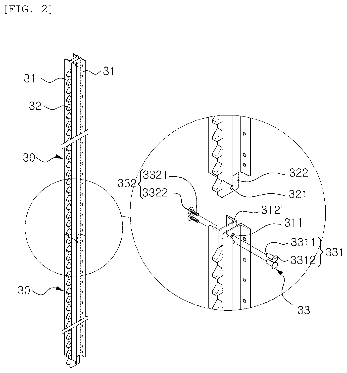
[0033] The climbing rail 30 may include a pair of C-shaped steel beams 31 having a connection hole 311 and a housing groove 312 on one side of the pair of C-shaped steel beams 31 and
[0034] a locking rack 32 provided between the pair of C-shaped steel beams 31 and in which the protrusion 322 provided with a connection hole 321 is protruding at one side thereof and teeth of a wedge shape thereof inclined to one side in the longitudinal direction are exposed, wherein
[0035] the exposed protrusion 322 of the locking rack 32 is inserted into the housing groove 312 of an adjacent climbing rail 30' and fastened thereto by a fastening member 33.
[0036] The cage 100 may further include a finishing cage 400 at a lower part thereof having an extended scaffold 410 for performing external work on the structure.
Advantageous Effects
[0037] As described above, the construction climbing system with improved structural stability according to the present invention minimizes the protruding part for connecting the climbing rails. The structural stability is achieved by improving the assembly structure of the climbing rails installed to have a similar length to the cage by connecting a plurality of climbing rails. Therefore, there is an effect that the construction climbing system moving in a vertical direction may move in a more stable state. The effect is achieved by preventing the cage movement from being obstructed due to the protruding part being caught by the shoe during the vertical movement of the cage.
[0038] In addition, the gang form is connected to the upper part of the cage in a structure capable of reversing, in other words, the lower surface of the gang form frame is contacted with upper surface of the cage frame with each other, so that the gang form has a structure to be moved back and forth by the gear coupling of the rack and the pinion. Accordingly, there is an effect that the gang form may be removed or installed in a state where left and right balances are maintained without biasing to one side, so that the gang form may be removed and moved stably.
[0039] In addition, when the worker is demolding and installing the gang form or working in the cage, an auxiliary scaffold that may be installed in close proximity to the position of the building on one side of a working scaffold is provided, and an improved bracket is also provided so that the installation state of the auxiliary scaffold may be firmly maintained. As a result, the work environment of the worker may be safely secured by providing the working radius for the worker as wide as possible, thereby preventing accidents such as falling of a worker or s working tool that may occur during the work.
DESCRIPTION OF DRAWINGS
[0040] FIG. 1 is a side view of a state in which a construction climbing system with improved structural stability according to the present invention is provided in a building.
[0041] FIG. 2 is a perspective view of the climbing rail of the construction climbing system with improved structural stability according to the present invention.
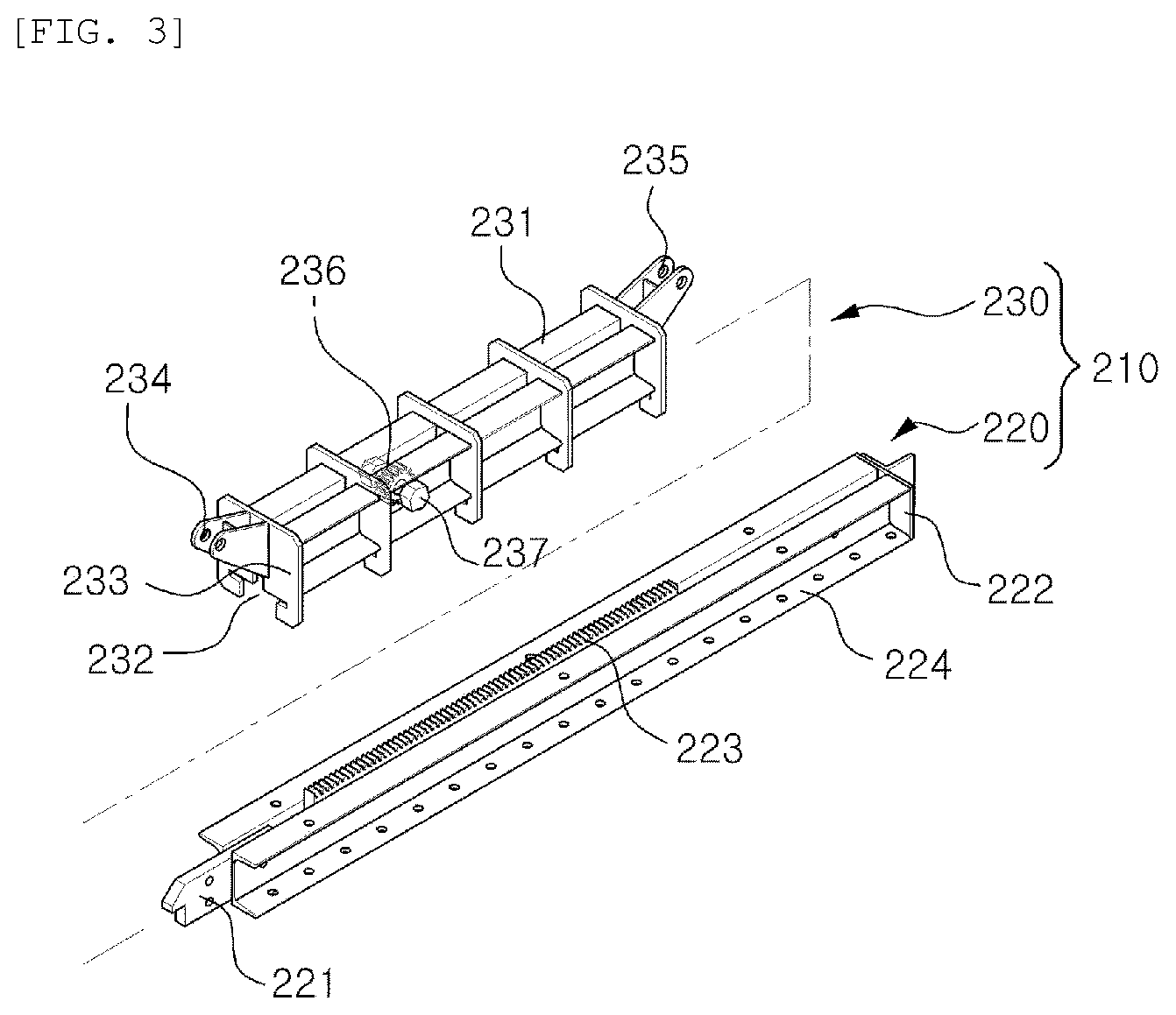
[0042] FIG. 3 is an exploded perspective view of the gang form moving-means part of the construction climbing system with improved structural stability according to the present invention.
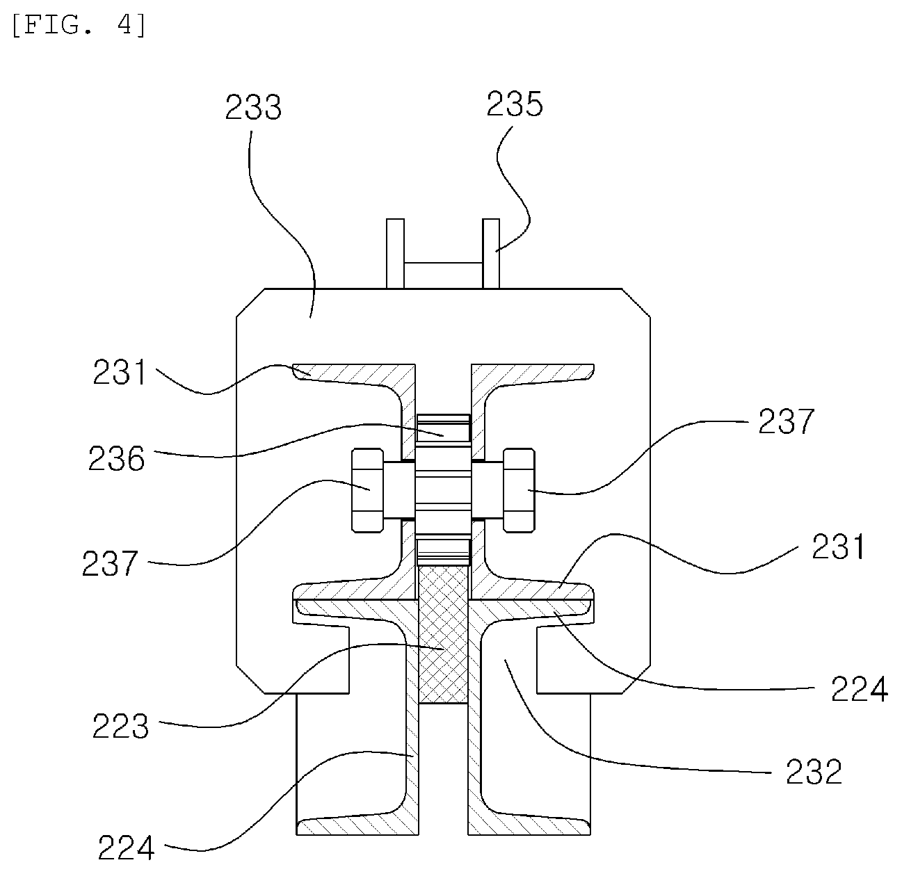
[0043] FIG. 4 is a cross-sectional view of the combined state of the gang form moving-means part of the construction climbing system with improved structural stability according to the present invention.
[0044] FIG. 5 is an enlarged view of part A of FIG. 1.
[0045] FIG. 6 is an enlarged view of part A of FIG. 1 and illustrates a state in which the gang form is moved backward.
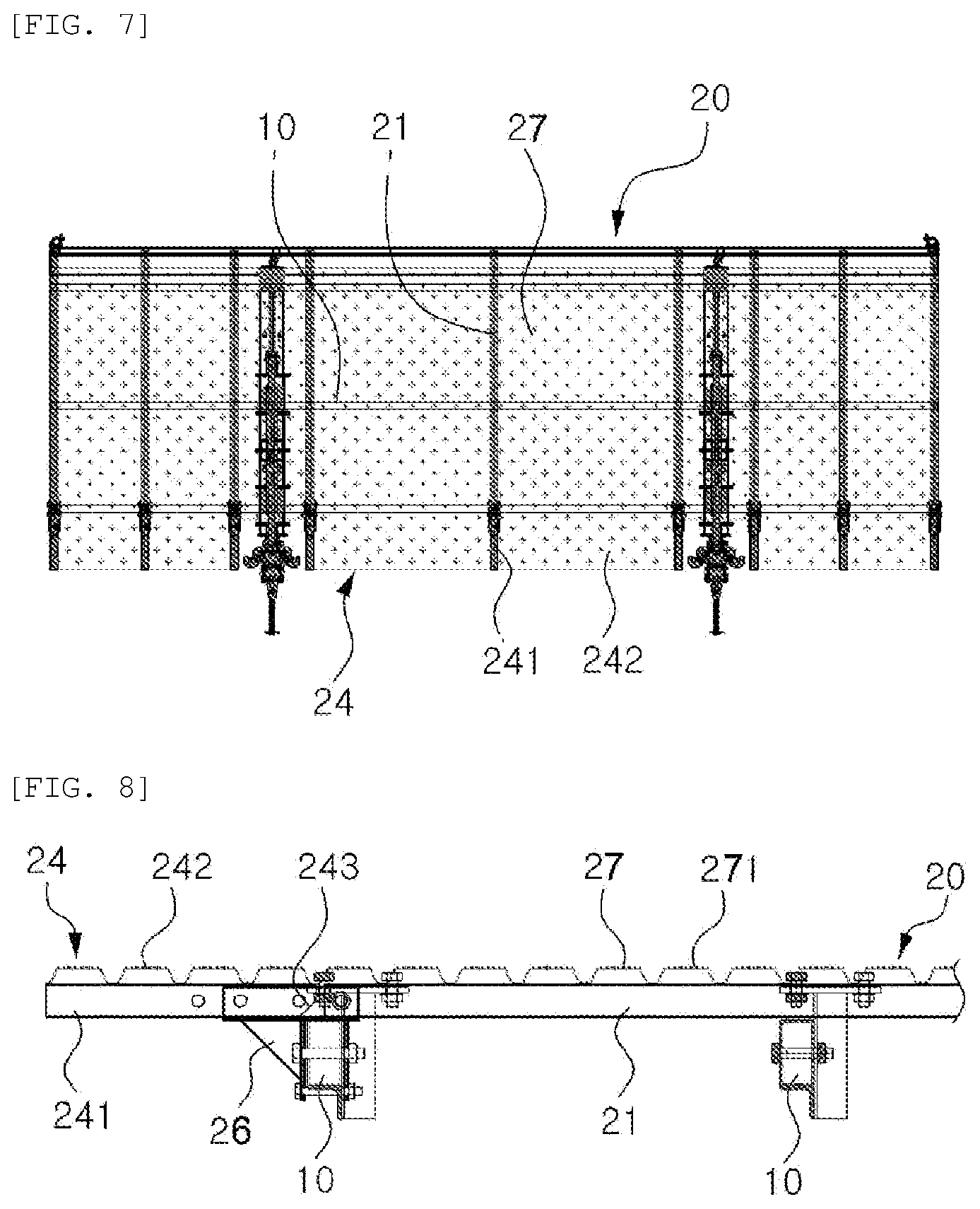
[0046] FIG. 7 is a plan view of a working scaffold part of the construction climbing system with improved structural stability according to the present invention.
[0047] FIG. 8 is a side view of a state in which an auxiliary scaffold is installed on one side of the working scaffold in the construction climbing system with improved structural stability according to the present invention.
[0048] FIG. 9 is a perspective view of a bracket for connection of the working scaffold and the auxiliary scaffold in the construction climbing system with improved structural stability according to the present invention.
[0049] FIG. 10 is a view of a modified state of the construction climbing system with improved structural stability according to the present invention.
[0050] FIG. 11 is a view showing a modified embodiment of the cage of the construction climbing system with improved structural stability according to the present invention.
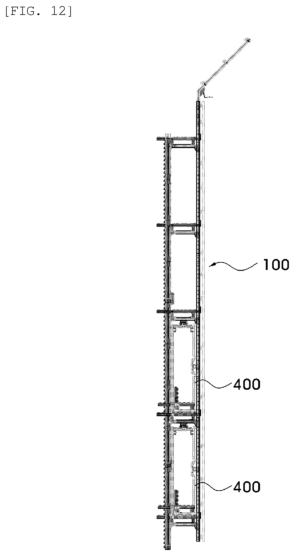
[0051] FIG. 12 is a view showing another modified embodiment of the cage of the construction climbing system with improved structural stability according to the present invention.
BEST MODE
[0052] Hereinafter, exemplary embodiments of the present invention will be described in detail with reference to the accompanying drawings.
[0053] The embodiments to be described below are intended to be described in detail so that those skilled in the art to which the present invention pertains may easily carry out the invention, and thus it does not mean that the technical spirit and scope of the present invention are limited.
[0054] In addition, the size or shape of the components shown in the drawings may be exaggerated for clarity and convenience of description, terms specifically defined in consideration of the configuration and operation of the present invention will vary depending on the intention or custom of the user or operator, and it should be understood that definitions of these terms should be made on the basis of the contents throughout the specification.
[0055] FIG. 1 is a side view of a state in which a construction climbing system with improved structural stability according to the present invention is provided in a building, and FIG. 2 is a perspective view of a climbing rail from the construction climbing system with improved structural stability according to the present invention. FIG. 3 is an exploded perspective view of the gang form moving-means part of the construction climbing system with improved structural stability according to the present invention, and FIG. 4 is a cross-sectional view of the combined state of the gang form moving-means part of the construction climbing system with improved structural stability according to the present invention. FIG. 5 is an enlarged view of part A of FIG. 1, and FIG. 6 is an enlarged view of part A of FIG. 1. FIG. 7 is a plan view of a working scaffold part of the construction climbing system with improved structural stability according to the present invention, FIG. 8 is a side view of an auxiliary scaffold in a state is installed on one side of the working scaffold of the construction climbing system with improved structural stability according to the present invention, and FIG. 9 is a perspective view of the bracket for the connection of the working scaffold and the auxiliary scaffold in the construction climbing system with improved structural stability according to the present invention.
[0056] As shown in the drawings, the construction climbing system with improved structural stability according to the present invention (hereinafter, referred to as a "climbing system") 1 largely includes a cage 100 provided in a structure or a building so as to be movable in the vertical movement, and a gang form 200 installed in a structure capable of moving forward and backward on the top of the cage 100.
[0057] The cage 100 has a frame 10 designed to have a height corresponding to one or two or more floors of a structure or building to be constructed, and a predetermined width and depth; a plurality of working scaffolds 20 installed inside the frame 10; a shoe 300 installed at one side of the frame to be installed in a building; and a climbing rail 30 assembled in a sliding-movable form.
[0058] The frame 10 is made as a unit of a predetermined standard to form an overall outer shape of the cage 100 of the present invention. That is, the frame may be assembled into a grid-like form by using a conventional steel frame, for example, a square pipe, including channel-shaped steel beam or H-shaped steel beam and the like.
[0059] In addition, the size of the frame 10 may be manufactured in an appropriate size in consideration of various site conditions, such as the size of the building to be constructed. In the case of a general building, it is proper that the width may be about 6 m to 15 m, and in the case of height, the height may be to cover about 2 to 4 floors, and the depth may be about 0.6 to 1.2 m.
[0060] In addition, the guidance rail 30 is assembled to one side of the frame 10 and a protective screen (not shown) such as a PE net, a wire mesh, or a tent is attached to the other side of the frame 10 to prevent falling the workers or falling objects, or to prevent dust or foreign substances generated during operation from flying into the air.
[0061] In addition, although the frame is shown to cover the height of the two floors of the building in the illustrated embodiment, a specific size may be adjusted in discretion according to conditions of a construction site. In addition, although not shown, it may be sufficiently considered for the frame 10 provided in a lattice shape to be structurally reinforced by a turn buckle or bracing as necessary.
[0062] The working scaffold 20 is to provide a space in which the worker working inside the cage 100 may safely work, and is assembled to the frame 10 as shown in FIGS. 7 to 9. Also, the working scaffold includes: a plurality of support bars 21 made of the same pipe or channel section steel, the same as the frame 10; a perforated scaffold 27 assembled to the upper part of the support bar 21; and an extension bracket 23 to which the auxiliary scaffold 24 is assembled to one side thereof and coupled to the frame 10 and the support bar 21.
[0063] The perforated scaffold 27 provides a protruding hole 271 protruding from the edge of the hole (not shown) to the upper part to prevent the worker from slipping during the work on the perforated scaffold.
[0064] The extension bracket 23 are integrally provided with a first fitting groove 261 to which the frame 10 is fitted at the bottom thereof and a second fitting groove 262 to which an auxiliary support bar 241 of the auxiliary scaffold 24 and the support bar 21 of the working scaffold 20 is fitted at the top thereof, and a plurality of fastening holes 263. Accordingly, the support bar 21 and the auxiliary support bar 241 are bolted to the second fitting groove 262 in a state in which the frame 10 is fitted into the first fitting groove 261 to be firmly fixed with a bolt (not shown). Therefore, the auxiliary scaffold 24 is connected to the frame 10 and the working scaffold 20 to maintain a firmly provided state.
[0065] In addition, the auxiliary scaffold 24 includes the auxiliary support bar 241 in which one side thereof is fastened to the second fitting groove 262 of the extension bracket 23 and an auxiliary perforated scaffold 242 assembled on the upper part of the auxiliary support bar 241.
[0066] Particularly, as an inclined surface 243 is provided at the end connected to the extension bracket 23 of the auxiliary support bar 241, the auxiliary scaffold 24 is rotatably provided without being caught upward in a state assembled to the extension bracket 23. Accordingly, when not being in use, the auxiliary scaffold 24 may be eliminated by removing it from the extension bracket 23 or by removing only a part of the fastening bolt and rotating the upper part to prevent the cage 100 in motion from being caught by the auxiliary scaffold 24.
[0067] Before being assembled and provided on one side of the frame 10, the climbing rail 30 is provided in such a manner that the climbing rail 30 has the same or similar height as that of the frame 10 by connecting a plurality of climbing rails to each other, like a prefabricated frame 10.
[0068] That is, the climbing rail 30 integrally provides a locking rack 32 having a wedge-shaped tooth inclined to one side between a pair of C-shaped steel beam 31 as shown in FIG. 2.
[0069] At this time, the locking rack 32 coupled between the C-shaped steel beam 31 protrudes from the end part thereof to the lower part of the C-shaped steel beam 31 to form a protrusion 322 having a connection hole 321. Also, the climbing rail provides a housing groove 312 having connection holes 311 at both sides with the same depth as the length of the protrusion 322 on the upper part thereof to connect to the protrusion 322 of the locking gear 32. Accordingly, the protrusion 322 is inserted into the housing groove 312' of the climbing rail 30' so that each of the connection holes 311' and 321 is located in the same line, and then climbing rail 30 and 30' are firmly connected to each other by being fastened with a fastening member 33.
[0070] In addition, since the fastening member 33 minimizes the part protruding to the outside while maintaining a firm connection state in connecting the plurality of climbing rails 30, the climbing rail 30 is not blocked in movement by minimizing jamming with the shoe 300 when the shoe 300 is in close contact with the outer surface of the climbing rail 30 afterward.
[0071] That is, the fastening member 33 penetrates the respective connection holes 311' and 321, and includes a female coupler 331 composed of a female screw hole 3311 and a convex lens-shaped female screw head 3312, and a male coupler 332 composed of a male screw body 3321 screwed into the female screw hole 3311 and a convex lens-shaped male screw head 3322. The fastening member 33 is to screw the male screw body 3321 of the male coupler 332 to the female screw hole 3311 in a state that the female coupler 331 is inserted into the connection hole 311 and 321 so as to expose the screw heads 3312 and 3322 of the male coupler 332 and the female coupler 331 to the outside of the connection hole 311'. Accordingly, when the climbing rail 30 moves while being connected to the shoe 300, only the convex-type screw heads 3312 and 3322 are exposed in minimum to ensure stable movement of the climbing rail without shaking due to the locking. Accordingly, when the climbing rail 30 is connected to the shoe 300 only the convex lens-shaped screw heads 3312 and 3322 are at least exposed, thereby ensuring stable movement of the climbing rail without shaking due to the locking.
[0072] Meanwhile, the gang form 200 is provided in a form that is movable forward and backward in the upper part of the cage 100, and includes: a base 210 assembled in a slidable form with the frame 10 in the lower part thereof; a moving frame 240 assembled with the frame 10 in a vertical direction; and an inclined support strut 250 which maintains the fastening state between the base 210 and the moving frame 240.
[0073] The base 210 is composed of a fixed base 220 fixed to the cage 100 and a moving base 230 assembled to be slidably movable with the fixed base 220. Since the moving frame 240 in which the formwork is installed on one side of the moving base 230 is assembled with the fixed base 220 by the inclined support strut 250 and installed in a form in which the inclination is adjustable, the base 210 ensures that the wall surface is being built in a state exactly perpendicular to the floor surface.
[0074] The fixed base 220 has a pair of C-shaped steel beam 224 facing to each other, and includes: a protruding part 221 positioned on one side thereof, and which may be caught by the shoe; a spacing plate 222 on the other side thereof; a part of the rack gear 223 protruding upwards in the middle thereof.
[0075] The moving base 230 is fixedly spaced apart at regular intervals by a method such as welding a plurality of fixed plates 233 having an insertion groove 232 in the lower part in a state in which the pair of C-shaped steel beam 231 is faced to each other. Also, the moving base may include: a first connection part 234 rotatably assembled with a lower part of the moving frame 240 on one side thereof; and a second connection part 235 rotatably assembled with the inclined support strut 250 on the other side thereof; and a gear 236 meshed with the rack gear 223 at a central part thereof, and rotatably assembled inside the pair of C-shaped steel beams 231, and a locking protrusion 237 protrudes outside the pair of C-shaped steel beam 231.
[0076] The fixed base 220 and the moving base 230 configured as described above are inserted into the insertion groove 232 of the moving base 230 by the upper part of the fixed base 220, so that the gear 236 of the moving base 230 is meshed with the rack gear 223 of the fixed base 220. At the same time, the lower surface of the C-shaped steel beam 231 of the moving base 230 is in close contact with the upper surface of the C-shaped steel beam 224 of the fixed base 220. Accordingly, in a state in which the moving base 230 is in surface contact with the upper surface of the fixed base 220 and stably supported, a wrench (not shown) is connected to the locking protrusion 237 protruding to both sides of the gear 236. Also, by manually rotating the gear 236, the moving base 230 is moved back and forth from the fixed base 220.
[0077] Moreover, the rotation of the gear 236 may be driven manually through a wrench (not shown) as described above, and in another embodiment, the gear 236 may be automatically controlled through a connection with a drive motor (not shown).
[0078] Also, the gang form 200 is fastened due to a protruding part 221 protruding on one side of the fixed base 220 by being caught by the shoe 300 installed on the building, thereby preventing workers from falling and ensuring the stable driving of the gang form 200.
MODE FOR INVENTION
[0079] Meanwhile, FIG. 10 is a view of a modified aspect of the construction climbing system with improved structural stability according to the present invention. In this embodiment, the finishing cage 400 having an extended working scaffold 410 for the finishing work of the building is integrally provided at the lower part of the cage 100. Accordingly, since it is not necessary to provide a separate temporary facility for external work of a building, the overall construction period of the building may be shortened, thereby reducing the temporary construction cost and construction period.
[0080] Meanwhile, FIG. 11 is a view showing a modified embodiment of the cage of the construction climbing system with improved structural stability according to the present invention. In the present embodiment, a configuration of the gang form among configurations of the climbing system is removed, and the climbing system is reconfigured with only the cage to perform an external finishing work of the structure.
[0081] In addition, FIG. 12 shows a modified mode of the cage shown in FIG. 11. As shown the above, an auxiliary cage 400 is provided to slidably move to both sides in the cage so as to expand the workspace to a wider form, thereby securing an exterior working space more efficient.
[0082] Although the present invention has been described in association with the above-mentioned preferred embodiments, it will be readily apparent to those skilled in the art that various modifications and variations may be made without departing from the spirit and scope of the invention, it is obvious that all such modifications and variations belong to the scope of the claims being attached.
INDUSTRIAL AVAILABILITY
[0083] As described above, the climbing system 1 according to the present invention includes the cage 100 built by utilizing the frame 10 designed to have a height corresponding to one or more floors, and to have a predetermined width and depth. Thus, the problem of load during maintenance and lifting may be improved due to light weight of the cage. Also, the climbing system 1 according to the present invention provides a stable working environment due to the expansion of the working space through a configuration of an auxiliary scaffold provided to the front side of the working scaffold. At the same time, by fastening the auxiliary scaffold using a separate bracket, a stable installation state may be maintained. In particular, the climbing system 1 according to the present invention minimizes the protrusion due to the assembly of the climbing rail installed in front of the cage 100 so as to make the vertical movement more smoothly and stably in connection with the shoe, thereby improving the stability of the work environment and the risk of falling.
[0084] In addition, in the case of the gang form installed in the upper cage, the moving base is connected to the fixed base firmly installed to the cage, in a form capable of moving forward and backward. In this case, by moving fixed base and moving base whose surfaces are contacted with each other, the bias of shifting to one side is prevented and the weight of the moving base is not transmitted to the meshing of the gear, thereby ensuring a stable movement of the gang form.
* * * * *
D00000
D00001
D00002
D00003
D00004
D00005
D00006
D00007
D00008
D00009
D00010
D00011
XML
uspto.report is an independent third-party trademark research tool that is not affiliated, endorsed, or sponsored by the United States Patent and Trademark Office (USPTO) or any other governmental organization. The information provided by uspto.report is based on publicly available data at the time of writing and is intended for informational purposes only.
While we strive to provide accurate and up-to-date information, we do not guarantee the accuracy, completeness, reliability, or suitability of the information displayed on this site. The use of this site is at your own risk. Any reliance you place on such information is therefore strictly at your own risk.
All official trademark data, including owner information, should be verified by visiting the official USPTO website at www.uspto.gov. This site is not intended to replace professional legal advice and should not be used as a substitute for consulting with a legal professional who is knowledgeable about trademark law.