Decoupling Sheet
KAISER; Uwe ; et al.
U.S. patent application number 16/604455 was filed with the patent office on 2020-05-14 for decoupling sheet. The applicant listed for this patent is EWALD DORKEN AG. Invention is credited to Thomas BACHON, Vasco GERACE, Ulrich GOERKE, Uwe KAISER, Tim Simon KROFFGES, Heinz Peter RAIDT, Birgit STRIEDER.
| Application Number | 20200149291 16/604455 |
| Document ID | / |
| Family ID | 62245211 |
| Filed Date | 2020-05-14 |
View All Diagrams
| United States Patent Application | 20200149291 |
| Kind Code | A1 |
| KAISER; Uwe ; et al. | May 14, 2020 |
DECOUPLING SHEET
Abstract
The invention relates to a decoupling sheet (1) having a carrier plate (2) and a plurality of nubs (4) protruding from the carrier plate plane (3). According to the invention, a plurality of protrusions (21a) and/or recesses (21b) is provided on the side of the nub base (10) of at least one nub (4) facing toward the nub interior space (20) and/or a plurality of protrusions (21c) and/or recesses (21d) is provided on the side of the carrier plate (2) facing toward the nub interior space (20), especially wherein the protrusion (21a) and/or the recess (21b) on the nub base (10) and/or the protrusion (21c) and/or the recess (21d) on the carrier plate (2) has a height and/or a depth greater than 1 .mu.m, preferably greater than 100 .mu.m, further preferably between 100 and 1000 .mu.m and especially at least substantially between 300 and 500 .mu.m.
| Inventors: | KAISER; Uwe; (Herdecke, DE) ; GERACE; Vasco; (Hagen, DE) ; KROFFGES; Tim Simon; (Herdecke, DE) ; STRIEDER; Birgit; (Bochum, DE) ; RAIDT; Heinz Peter; (Dortmund, DE) ; GOERKE; Ulrich; (Herdecke, DE) ; BACHON; Thomas; (Dusseldorf, DE) | ||||||||||
| Applicant: |
|
||||||||||
|---|---|---|---|---|---|---|---|---|---|---|---|
| Family ID: | 62245211 | ||||||||||
| Appl. No.: | 16/604455 | ||||||||||
| Filed: | April 23, 2018 | ||||||||||
| PCT Filed: | April 23, 2018 | ||||||||||
| PCT NO: | PCT/EP2018/060325 | ||||||||||
| 371 Date: | October 10, 2019 |
| Current U.S. Class: | 1/1 |
| Current CPC Class: | E04F 15/182 20130101; E04F 15/0215 20130101; E04F 15/186 20130101; E04F 15/185 20130101; E04F 15/02194 20130101 |
| International Class: | E04F 15/02 20060101 E04F015/02 |
Foreign Application Data
| Date | Code | Application Number |
|---|---|---|
| Apr 26, 2017 | DE | 10 2017 004 002.8 |
Claims
1. A decoupling sheet having a carrier plate and a plurality of nubs protruding from the carrier plate plane, wherein a plurality of protrusions and/or recesses is provided on the side of the nub base of at least one nub facing toward the nub interior space and/or a plurality of protrusions and/or recesses is provided on the side of the carrier plate facing toward the nub interior space, especially wherein the protrusion and/or the recess on the nub base and/or the protrusion and/or the recess on the carrier plate has a height and/or a depth greater than 1 .mu.m, preferably greater than 100 .mu.m, further preferably between 100 and 1000 .mu.m and especially at least substantially between 300 and 500 .mu.m.
2. The decoupling sheet according to claim 1, wherein more than 20, preferably more than 100, further preferably more than 1000, preferably more than 10000 protrusions and/or recesses are provided, wherein the protrusions and/or recesses, are arranged in an irregular or unordered manner preferably on both the nub base and on the carrier plate.
3. The decoupling sheet according to claim 1, wherein at the protrusions and/or the recesses form a structured surface of the nub base and/or the carrier plate and/or the protrusions and/or recesses comprise different shapes and/or structures and/or at least one protrusion at least one recess comprises at least one shaping, especially a sickle shape and/or an arc segment shape and/or a crescent shape, to form an undercut.
4. The decoupling sheet according to claim 1, wherein the nub has multiple legs, especially wherein a plurality of protrusions and/or recesses is provided on the leg bottom of a leg and/or nubs immediately adjacent transversely to the lengthwise direction and in the lengthwise direction of the carrier plate have a triaxial nub base, especially one with at least three leg sides.
5. The decoupling sheet according to claim 1, wherein the protrusion and/or recess on the nub base is formed in the shape of a spiral and/or an arc segment and/or a protrusion in shape of a spiral and/or recess is provided in the middle region of the nub base.
6. The decoupling sheet according to claim 1, wherein protrusions and/or recesses in the shape of an arc segment are provided about the center point of the nub on the leg bottom, concentric to the middle region, and/or the protrusions and/or recesses of the nub base are web-like and/or have a rectangle shape and/or ellipse shape.
7. The decoupling sheet according to claim 1, wherein web-like and/or rectangular and/or elliptical protrusions and/or recesses on the nub base are oriented transversely and/or longitudinally to the lengthwise direction of the carrier plate and/or a plurality of protrusions and/or recesses are provided on the carrier plate and the protrusions and/or recesses are arranged in rows running longitudinally and transversely to the lengthwise direction of the carrier plate and/or the protrusions and/or recesses of the carrier plate are web-like and/or of rectangle and/or ellipse shape and/or the protrusions and/or recesses of the carrier plate are elongated and oriented by their longitudinal extension solely transversely and/or longitudinally to the lengthwise direction of the carrier plate and/or protrusions and/or recesses running in a row transversely and/or longitudinally to the lengthwise direction of the carrier plate are arranged in alternating orientation.
8. The decoupling sheet according to claim 1, wherein at least one nub having a triaxial nub base is provided with three long sides and the middle region of the triaxial nub base is defined by a circle which all the long sides contact tangentially.
9. The decoupling sheet according to claim 1, wherein the nub has a concave shape on at least one long side.
10. The decoupling sheet according to claim 1, wherein at least one shaping especially in the form of a sickle and/or an arc segment and/or a crescent is formed in the region of the long side and/or leg side of the nub in order to form an undercut on the interior of the nub, wherein the shaping is particularly formed by a protrusion protruding out from the nub interior space.
11. The decoupling sheet according to claim 1, wherein the protrusion is provided in the region of the nub base, in particular that it passes directly into the nub base and/or the shaping extends for at least 40%, preferably between 50% and 100% and especially between 60% and 90%, of the long side and/or the leg side.
12. The decoupling sheet according to claim 1, wherein the end region formed by two converging long sides is free of undercuts and/or the nub is formed rounded and without corners at least at one end region resulting from two converging long sides and/or the radius of a long side is multiple times longer than the radius of an end region, preferably the radius of a long side is twice as large as the radius of an end region.
13. The decoupling sheet according to claim 1, wherein the nub and/or the triaxial nub base has mirror symmetry with respect to a center axis running at least substantially parallel to the lengthwise direction and/or three spaced-apart legs are provided, emerging from the middle region, wherein the angle of spaced-apart leg axes is at least 90.degree. and/or the leg length of one leg, especially that of the leg running parallel to the center axis, is less than the other two leg lengths, and/or the angle of the leg axis of the shorter leg with respect to the leg axis of the adjacent leg is greater than 120.degree. and especially less than 130.degree..
14. The decoupling sheet according to claim 1, wherein nubs running transversely to the lengthwise direction of the carrier plate are arranged such that no straight line running transversely to the lengthwise direction of the carrier plate is formed continuously on the carrier plate and/or nubs running in the lengthwise direction of the carrier plate are arranged such that no straight line running in the lengthwise direction the carrier plate is formed continuously on the carrier plate and/or nubs running longitudinally and transversely to the lengthwise direction of the carrier plate are arranged such that no straight line running at a slant to the lengthwise direction of the carrier plate is formed continuously on the carrier plate.
15. The decoupling sheet according to claim 1, wherein the nubs are arranged in rows running in the lengthwise direction and transverse direction, wherein the center points of the nubs running in the lengthwise direction are arranged on a line running at least substantially parallel to the lengthwise direction and/or the center points of the nubs running transversely to the lengthwise direction are arranged on a line running at least substantially perpendicular to the lengthwise direction.
16. The decoupling sheet according to claim 1, wherein the shorter leg of the nubs arranged in a row of successively arranged nubs running at least substantially parallel to the lengthwise direction is oriented in the lengthwise direction and the shorter leg of the nubs arranged in the immediately adjacent row of successively arranged nubs running at least substantially parallel to the lengthwise direction is oriented opposite to the lengthwise direction.
17. The decoupling sheet according to claim 1, wherein a flat connection means is provided, in particular fastened, on the outside of the nub base for connecting to the ground, and preferably the connection means is embodied as a nonwoven and/or a textile and/or paper and/or a scrim and/or a lattice, especially across the entire surface and/or in a lattice shape.
18. The decoupling sheet according to claim 1, wherein the nub has a height between 1 and 5 mm, preferably between 1 and 4 mm, further preferably between 2.5 and 3.5 mm, and/or the clear gap between adjacent nubs is greater than 2 mm, in particular, there is a clear gap between 3 mm and 9 mm, preferably between 4 and 8 mm, further preferably between 5 and 6 mm, and/or the ratio of the area of the nub bases of all the nubs to the area of the carrier plate is between 40% and 70%, preferably between 45% and 55% and especially at least substantially 50%.
19. A method for production of a decoupling sheet having a carrier plate and a plurality of nubs protruding from the carrier plate plane, wherein a plurality of protrusions and/or recesses is placed in the side of the nub base of at least one nub facing toward the nub interior space and/or a plurality of protrusions and/or recesses is placed in the side of the carrier plate facing toward the nub interior space.
20. The method for production of a decoupling sheet according to claim 19, wherein in that the nub bases immediately adjacent nubs have a triaxial shape transversely to the lengthwise direction and in the lengthwise direction of the carrier plate.
21. The method according to claim 19, wherein the protrusion and/or the recess is made by a laser process, a plasma process, a machining process, preferably blasting, especially using sand and/or nutshells, and/or by embossing during and/or after the production of the decoupling sheet.
Description
CROSS REFERENCE TO RELATED APPLICATIONS
[0001] This application is a national stage application under 35 U.S.C. 371 of PCT Application No. PCT/EP2018/060325 having an international filing date of 23 Apr. 2018, which designated the United States, which PCT application claimed the benefit of German Application No. 10 2017 004 002.8, filed 26 Apr. 2017, each of which are incorporated herein by reference in their entirety.
SUMMARY
[0002] The invention relates to a decoupling sheet having a carrier plate and a plurality of nubs protruding from the carrier plate plane.
[0003] In the present application, the term "decoupling" is understood to mean the reduction of shear stresses and/or stress peaks between two layers arranged in a fixed laminate. An effective decoupling thus prevents shear stresses and/or stress peaks which are present in one of the layers from being transmitted to the other layer of the laminate structure and possibly causing damage there.
[0004] Decoupling sheets of the aforementioned kind are used for example in the construction industry when laying floors, especially for decoupling, sealing, and/or vapor pressure equalization. The decoupling sheets are installed, in particular glued, on an ground and form the bearing layer for flooring elements such as ceramic tiles. The installation of tiles is performed in particular on young screed in the thin-bed method. If no decoupling sheet is installed between the tiling and the young screed, upon shrinkage of the screed the tiles might not follow the movement of the screed especially on account of their low coefficient of expansion, so that shear stresses will be created, ultimately leading to the detachment or even the breaking of the tiles. Decoupling sheets are also required when installing flooring on especially critical grounds, such as old wooden floors. A decoupling sheet of the aforementioned kind compensates for these shear stresses by deforming, so that no damage to the laminate structure is to be feared. Usually the decoupling sheets are made from filmlike plastic, i.e., from a flexible plastic layer, which is deformed under the action of external forces. The material is generally chosen to be low in emissions, especially as regards harmful substances.
[0005] For the attachment of the flooring elements to the decoupling sheet, a thin layer of a tile adhesive, also known as adhesive mortar or a bonding layer, is usually applied to the bearing plane of the decoupling sheet. It is understood that, in place of a tile adhesive, an equally suitable adhesive or fastening layer and/or a corresponding material can also be provided. Tile adhesives are usually combed with a notched trowel or a toothed smoothing trowel, and a different tile adhesive will be used according to the area of application and/or the ground. For example, a reactive resin adhesive, a thin-bed cement mortar, a casein tile adhesive or a dispersion adhesive will be used as the tile adhesive.
[0006] After applying the tile adhesive to a decoupling sheet, the individual flooring elements and/or tiles will be installed on the tile adhesive. During this application, the tile adhesive penetrates into the recesses of the decoupling sheet and becomes hardened.
[0007] In decoupling sheets of this kind, the joined flooring elements are separated from the ground and mechanically decoupled. Thanks to the arrangement of the nubs transversely to the lengthwise direction and in the lengthwise direction of the carrier plate, channels arise which extend over the entire carrier plate. These channels interact with the nubs so that they intercept and compensate for mechanical loadings and particularly shear stresses. This loading of the flooring elements can be created by means of temperature and moisture influences and/or by the application of weight.
[0008] In the manufacture of decoupling sheets of this kind, a molding die having protrusions corresponding to the recesses and/or nubs is used. The stripping of the molding die from the decoupling sheet is usually problematic, however. Furthermore, the decoupling sheet may become damaged during the mold stripping, especially if the protrusions of the die have sharp edges which cut into the usually still-soft decoupling sheet material and/or rip it open. There have been attempts to solve the latter problem in practice by providing the corners of the mold protrusions with a radius.
[0009] Decoupling sheets of the aforementioned kind are known for example from EP 2 372 041 B1 and from EP 2 246 467 B1.
[0010] EP 2 372 041 B1 relates to a method for the production of a carrier plate as well as to a carrier plate for a sheet-clad floor, wall or ceiling assembly in order to achieve a decoupling between the ground and the surface covering to be placed on top of the filmlike sheet, the carrier plate comprising a filmlike sheet with a plurality of chambers formed by recesses from one plane of the filmlike sheet, whose end faces form a first sheet side and opposite to this a second sheet side. A bond-strengthening layer of a sheet-like material is placed at least on one sheet side, lining at least the recesses of the chambers. The bond-strengthening layer is supposed to aid in better decoupling and, furthermore, to aid in better attachment of the tile adhesive. The recesses serve to receive the tile adhesive, which is placed on the top side on the bond-strengthening layer of the decoupling sheet. In the known decoupling sheet, round, cylindrical and/or pot-shaped shapings are provided as the recesses.
[0011] Instead of a bond-strengthening layer and/or in addition to this, it is known from EP 2 246 467 B1 that an improved adherence of the tile adhesive should be possible by applying a multitude of fibers to the top side of the decoupling sheet, facing toward the tile adhesive. The nubs and/or recesses of this known decoupling sheet have a round, cylindrical and/or pot-like shape and are accordingly rounded. The fibers applied to the top surface of the decoupling sheet are permanently joined to this surface. The tile adhesive in this case is placed into the recesses of the carrier plate.
[0012] The decoupling sheets known from EP 2 372 041 B1 and EP 2 246 467 B1 have regularly arranged round, cylindrical shapings which are arranged in rows and columns. Thanks to the arrangement, channels are formed between the rows of nubs, extending over the entire decoupling sheet. These channels are open toward the ground and intersect with other channels. When the tile adhesive is applied, the channels are only partly covered with a thin coat of the tile adhesive, so that they form a weakening line which favors a deformation of the decoupling sheet along this weakening line. In an unfavorable arrangement, the lay of the joint of adjacent flooring elements would coincide with a weakening line and/or predetermined breaking point, so that hairline cracks and/or larger damaged areas will arise in the tile mortar layer and/or in the joint itself.
[0013] The drawback to the known decoupling sheets is that they have deficient decoupling properties between the flooring elements and the ground without the use of the additional bond-strengthening layer and/or without additional fibers. The production of such decoupling sheets is costly, since an additional step of applying the bond-strengthening layer and/or additional fibers is provided in order to increase the adherence between the tile adhesive and the surface of the decoupling sheet facing toward the tile adhesive layer.
[0014] Now, the problem which the present invention proposes to solve is to provide a decoupling sheet which achieves an improved grip of the tile adhesive on the decoupling sheet.
[0015] Furthermore, the problem which the present invention in particular proposes to solve is to provide a simple and efficient method for the production of a decoupling sheet.
[0016] The aforementioned problem is essentially solved according to the invention in a decoupling sheet of the kind mentioned above in that a plurality of protrusions and/or recesses is provided on the side of the nub base of at least one nub facing toward the nub interior space and/or a plurality of protrusions and/or recesses is provided on the side of the carrier plate facing toward the nub interior space.
[0017] Preferably, the structuring and/or the recesses and/or the protrusions of the nub base and/or of the carrier plate has a height and/or a depth greater than 1 .mu.m, preferably greater than 100 .mu.m, further preferably between 100 and 1000 .mu.m and especially at least substantially between 300 and 500 .mu.m. If a protrusion directly adjoins a recess, with the protrusion protruding from the plane of the nub base and/or the carrier plate and the recess protruding into the nub base and/or the carrier plate, the spacing between the lowest point of the recess and the highest point of the protrusion is preferably greater than 50 .mu.m, further preferably greater than 100 .mu.m, further preferably between 100 and 300 .mu.m and especially at least substantially between 300 and 800 .mu.m.
[0018] In another advantageous embodiment of the idea of the invention, it is provided that the protrusions and/or the recesses on the nub base form a structured surface of the nub base and/or the carrier plate.
[0019] Preferably more than 20, preferably more than 100, further preferably more than 1000, preferably more than 10000 protrusions and/or recesses are provided on the nub base and/or on the carrier plate, wherein the protrusions and/or recesses are arranged irregularly and/or without order preferably on both the nub base and on the carrier plate. Thanks to a large number of protrusions and recesses, a structured surface of the decoupling sheet is produced.
[0020] Advantageously in this context, the most diverse forms and/or structures of the recesses and/or protrusions are provided, in particular wherein the shapes and/or structures of the protrusions and/or recesses result from the manner of producing the protrusions and/or recesses.
[0021] Finally, it is preferably provided according to the invention that a structured surface is formed for better anchoring of the tile adhesive, wherein a structuring of the surface results by virtue of protrusions and/or recesses. As is explained below, the protrusions and/or recesses may have a fixed geometrical shape, in particular being embossed during the manufacturing of the decoupling sheet, and/or they comprise the most diverse structures and/or shapes, it being essential to the invention that the protrusions and/or recesses have a maximum height and/or depth of more than 1 .mu.m.
[0022] In another preferred variant embodiment, a shaping is provided in order to form an undercut on the protrusions and/or recesses. This shaping forms the undercut, especially wherein the undercut serves for better anchoring of the tile adhesive to the surface of the carrier plate and/or of the nub base, wherein the tile adhesive preferably takes hold in the region of the undercut and becomes anchored there.
[0023] Advantageously, it is provided for a structuring of the nub base and/or the carrier plate that at least 30% of the free surface of the nub base and/or the carrier plate is structured and/or comprises recesses and/or protrusions. Preferably, over 50% of the carrier plate and/or over 50%, preferably over 70%, further preferably 80%+/-5%, of the overall surface of all nub bases is structured and/or comprises recesses and/or protrusions. This structured surface ensures a better anchoring of the tile adhesive and an increased bond strength for the entire decoupling sheet. Preferably, the surface of the carrier plate and/or the nub bases is entirely roughened and/or structured.
[0024] Hence, it is provided that a plurality of projecting protrusions are present on the nub base and/or the carrier plate, between which recesses are provided, serving for the gripping/bonding with the tile adhesive being applied to the decoupling sheet on the tile side. The protrusions are simply elevations and/or outcroppings of material. The recesses do not involve breaches in the nub base and/or the carrier plate allowing an exchange of air and/or moisture from the bottom side to the tile side. The same holds for the protrusions, which likewise have no openings or breaches and therefore likewise do not allow any exchange of air or moisture from the bottom side to the tile side.
[0025] The aforementioned embodiment of the invention enlarges the exposed surface of the nub bases and the surface of the carrier plate facing away from the nub bases, i.e., the surface of the webs provided on the carrier plate between the individual nub openings protruding into the nub interior spaces. The protrusions and/or recesses and the accordingly enlarged surface provide an improved grip of the tile adhesive. The protrusions and/or recesses according to the invention also improve the mold stripping of the overall decoupling sheet. The protrusions and/or recesses result in particular in the decoupling sheet having increased bending stiffness and/or torsional stiffness.
[0026] In the course of the creation of the invention, it was ascertained in experiments which were conducted that the protrusions and/or recesses in the nub base and/or in the carrier plate produce an improved bond strength of up to 40% as compared to the known decoupling sheet and consequently a significantly improved grip of the tile adhesive to the decoupling sheet.
[0027] The aforementioned realization of the protrusions and/or recesses and/or the structured surface of the carrier plate and/or the nub base can be realized in the above-described manner on basically every nub base and/or nub, regardless of the kind of configuration of the nub and/or nub base. Thus, the nub looking down on it in a top view may have for example an elliptical, especially a round, or also a quadrangular, especially rectangular and/or square, shape.
[0028] Preferably, adjacent nubs are arranged transversely to the lengthwise direction of the carrier plate and in the lengthwise direction of the carrier plate, especially in rows.
[0029] In an especially advantageous embodiment, it is provided that the nub is multi-legged. The multi-legged formation of the nub in combination with the arrangement of adjacent nubs transversely to the lengthwise direction of the carrier plate and in the lengthwise direction of the carrier plate enables in particular an optimal distribution between the exposed surface of the carrier plate and the nub surface. This ratio is critical to determining the drainage and decoupling properties. With a multi-legged formation of the nub, it has been established in the experiments conducted that the decoupling properties can be improved many times over. Preferably, a plurality of protrusions and/or recesses is provided on the leg bottom of a leg.
[0030] Furthermore, in one advantageous embodiment of the idea of the invention there is provided an arrangement of immediately adjacent nubs transversely to the lengthwise direction and in the lengthwise direction of the carrier plate, wherein immediately adjacent nubs have a triaxial nub base, especially one with at least three leg sides.
[0031] By a triaxial formation of the nub base is meant a three-legged formation in a two-dimensional extension. The nub base and/or the nub accordingly has three legs. For the three-dimensional forming of the nub, it is provided that at least one side wall adjoins the nub base in order to form the nub interior space.
[0032] The triaxial nub shape is seen in a top view looking down on the decoupling sheet.
[0033] First of all, the triaxial formation of the nub base is distinguished in that a simple manufacturing of the decoupling sheet according to the invention is ensured. This manufacturing makes it possible in particular to accomplish high processing speed, preferably by a so-called inline process, wherein the decoupling sheet is manufactured continuously with a relatively high production speed. The increased production speed is made possible in particular by providing a quick and easy mold stripping of the decoupling sheet according to the invention. An increased processing speed results in particular in a decrease in the production time and thus a savings on production costs.
[0034] The nubs according to the invention and the nub arrangement according to the invention furthermore afford the possibility of an easy buttering of the decoupling sheet with tile adhesive. This buttering is especially simplified in that a triaxial form of the nubs is chosen, so that the tile adhesive can be well distributed within this nub form when applying the adhesive and placing it in the nubs and the air can easily escape from the recesses.
[0035] In addition, a good drying and a very good vapor pressure equalization is ensured, since the channels formed between adjacent nubs in the decoupling sheet according to the invention are joined together directly and/or indirectly over the entire nub sheet. Thanks to the triaxial nub shape of the nub base, the channels are preferably rounded and/or wavy, yielding a full-surface vapor pressure equalization without interruption and at the same time a good dehumidification and ventilation. Thanks to the configuration of the decoupling sheet according to the invention, the decoupling sheet can be placed in particular on a moist and possibly not fully hardened ground without the moisture still present in the ground becoming trapped and/or preventing or excessively delaying the desired drying of the ground, especially thanks to the very good vapor pressure equalization. Consequently, the decoupling sheet can be installed soon after the production of the ground. This produces the advantage in particular that the installation time of the overall floor cover can be drastically reduced, a rapid work sequence is ensured, and the production costs of the flooring are accordingly reduced.
[0036] Furthermore, the nub sheet according to the invention has improved decoupling properties, since an improved load distribution is achieved by a triaxial nub shape of the nub base, preferably in combination with the orientation of the nubs in rows in the lengthwise direction and transversely to the lengthwise direction of the carrier plate, with a middle region which is defined by a circle. Furthermore, stress peaks are reduced or entirely avoided in some cases. The shear stresses are transmitted to the decoupling sheet and distributed in particular on the surface of the carrier plate facing toward the nubs. The distinctly improved load distribution is additionally achieved advantageously by the channel structure. The decoupling effect is advantageously such that, on the one hand, no cracks are created in the surface of the flooring facing away from the decoupling sheet and on the other hand possible cracks in the ground, which only arise in particular after the installation of the decoupling sheet, do not become evident in the tile adhesive layer and/or on the flooring elements.
[0037] In experiments that were conducted it was established that the decoupling properties were improved by up to 30% when using the nub having the triaxial nub base as compared to the decoupling sheet known in the prior art.
[0038] Besides a distinctly improved mold stripping and enhanced decoupling properties, the nub shape according to the invention furthermore ensures a greater strength of the tile bonding, since the tile adhesive is distributed very well in the recess produced in this way and in the recesses between the protrusions, and an interaction between the carrier plate and the nubs results in greater strength. Along with this, the bond strength of the overall decoupling sheet is increased. In particular, no additional bond-strengthening layer or supplemental fibers are required, so that in particular the production costs and/or the production time can be reduced.
[0039] The bond strength serves as a parameter of the adhesion of layers to grounds, especially concrete surfaces. It is determined by means of special testing, also known as a bond strength test and/or pull-off test. DIN EN 1348 contains instructions for determining the bond strength under defined conditions.
[0040] Thanks to the increased strength of the tile bonding and the improved decoupling properties, a lower overall layer assembly height of the decoupling sheets according to the invention can be selected as compared to the decoupling sheet known in the prior art. This smaller overall layer assembly means, among other things, that less tile adhesive is needed during the installation for the bonding of the flooring elements to the decoupling sheet, so that there are lower production costs for the flooring being laid.
[0041] The decoupling sheet according to the invention furthermore has a high torsional strength, preferably while preserving a good winding capability. The high torsional strength and/or torsional stiffness means that the decoupling sheet cannot bend and/or twist, especially by 90.degree.. Yet the preserved winding capability means that the decoupling sheet can be rolled up, preferably for transport.
[0042] In a further embodiment, it is provided that the decoupling sheet has a low torsional strength, so that the decoupling sheet can kink and/or twist in particular. Preferably, a rectangular shape of the nub is chosen in this variant embodiment.
[0043] Furthermore, it has been established in experiments that were conducted that, besides its excellent decoupling properties, the decoupling sheet according to the invention also has very good footfall muffling. This effect as well is a result of the special nub shape and arrangement.
[0044] In an especially advantageous embodiment, it is provided that the protrusion and/or recess on the nub base is formed in the shape of a spiral and/or an arc segment. It has been established that the spiral and/or rounded form of the protrusion and/or recess in particular results in an improved grip of the tile adhesive. Finally, it has been determined during experiments that it is especially advantageous when the protrusion in the shape of a spiral and/or recess is provided in the middle region of the nub base.
[0045] Moreover, it is understood that a plurality of protrusions and/or recesses can be provided on the nub base, so that the bond strength between the decoupling sheet and the flooring elements is increased.
[0046] Accordingly, in a further preferred embodiment in connection with the three-legged nub and/or the nub having a three-legged nub base, it is provided that the leg bottom of a leg of the nub has a plurality of protrusions and/or recesses.
[0047] In another preferred embodiment of the invention, the protrusions and/or recesses are arranged concentric to the middle region and/or to the center point of the nub on the leg bottom.
[0048] Furthermore, it has been established that it is especially advantageous for the protrusions and/or recesses of the nub base to be web-like and/or have a rectangular and/or elliptical shape. In this regard, it is especially preferable for the web-like and/or rectangular and/or elliptical protrusions and/or recesses on the nub base to be oriented transversely and/or longitudinally to the lengthwise direction of the carrier plate. This arrangement of the protrusions and/or recesses on the nub base enables in particular an easy buttering of the decoupling sheet with the tile adhesive along with good stripping of the nub sheet from the mold.
[0049] It is understood that not only can protrusions and/or recesses be placed on the nub base, but also in a further preferred embodiment protrusions and/or recesses may also be provided alternatively or additionally to the protrusions and/or recesses on the nub base likewise on the carrier plate and/or the carrier plate webs between the nub openings protruding into the nub interior spaces, and this both in the lengthwise direction of the carrier plate and in the transverse direction of the carrier plate. This arrangement of the protrusions and/or recesses on the carrier plate produces good bond strength, especially in combination with a preferred embodiment of the protrusions in web-like and/or rectangular and/or elliptical shape.
[0050] Furthermore, in another preferred embodiment of the invention it is provided that the protrusions and/or recesses of the carrier plate are elongated and oriented by their longitudinal extension solely transversely and/or longitudinally to the lengthwise direction of the carrier plate. This orientation in combination with the elongated shape brings about in particular a better grip of the tile adhesive on the carrier plate.
[0051] In an especially preferred embodiment of the invention, a special arrangement of the protrusions and/or recesses is provided by which they run in rows transversely and/or longitudinally to the lengthwise direction of the carrier plate and are arranged in alternating orientation. Precisely such a formation and arrangement produces a good grip of the tile adhesive on the carrier plate.
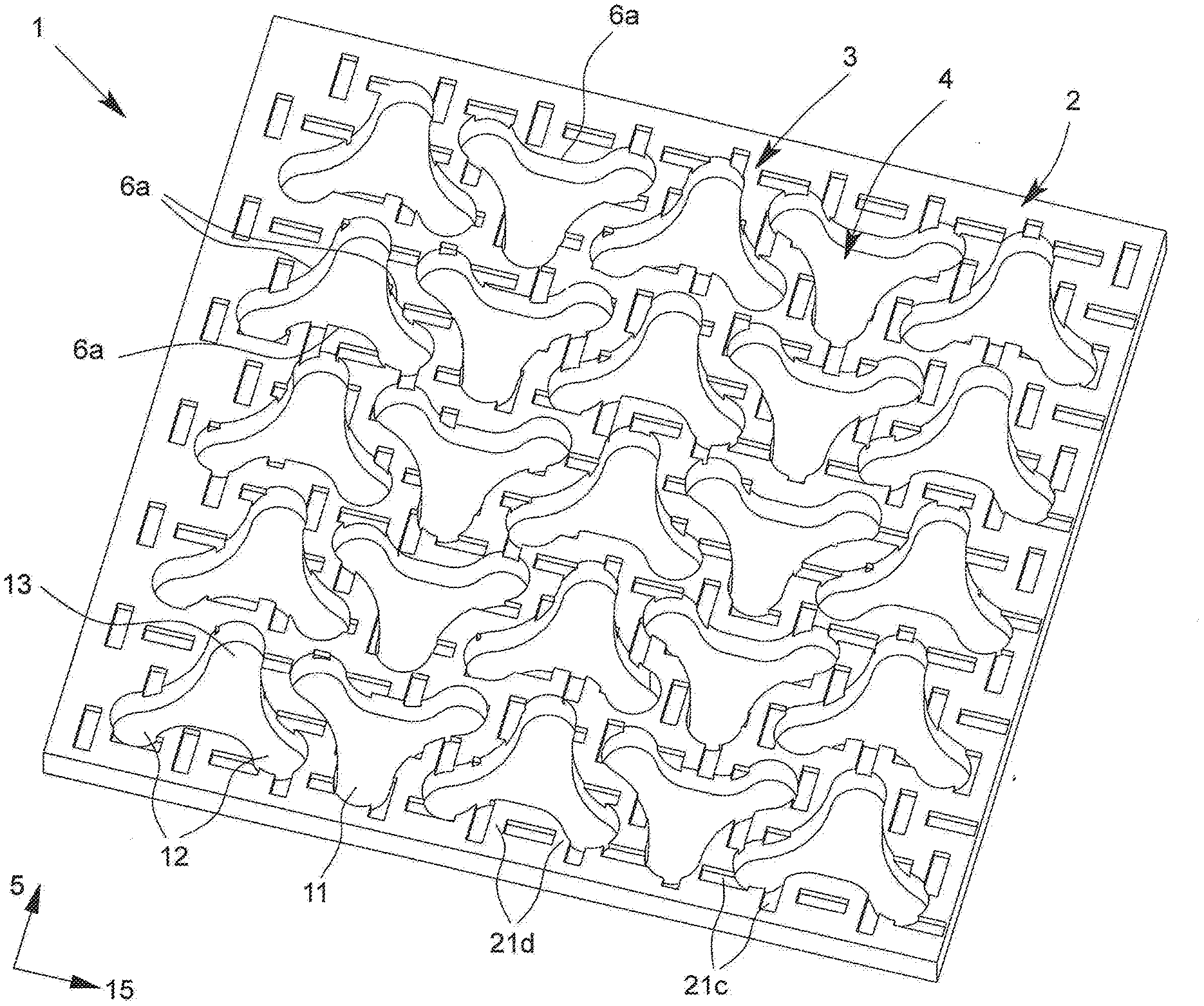
[0052] Preferably, at least one nub having a triaxial nub base is provided with three long sides and the middle region of the triaxial nub base is defined by a circle which all the long sides contact tangentially. This geometrical configuration of the nub and/or the nub base enables especially good decoupling properties with an excellent drainage function at the same time.
[0053] In one advantageous embodiment of the idea of the invention, the nub and/or the nub base has a concave shape on at least one long side. This concave shape of the long side means that an improved mold stripping can occur, since in particular no corners are present between the long sides. An improved mold stripping means an easier and/or improved manufacturing process.
[0054] Furthermore, in one preferred embodiment of the decoupling sheet according to the invention at least one shaping is provided in the region of the long side and/or leg side of the nub and/or the nub base in order to form an undercut on the interior side of the nub. It is understood that the long side is formed for example by two and/or one leg side. The tile adhesive penetrates into the undercut during the buttering, so that a better grip is produced. This, in turn, results in a securing of the tile set and/or flooring elements to be applied on the decoupling mat.
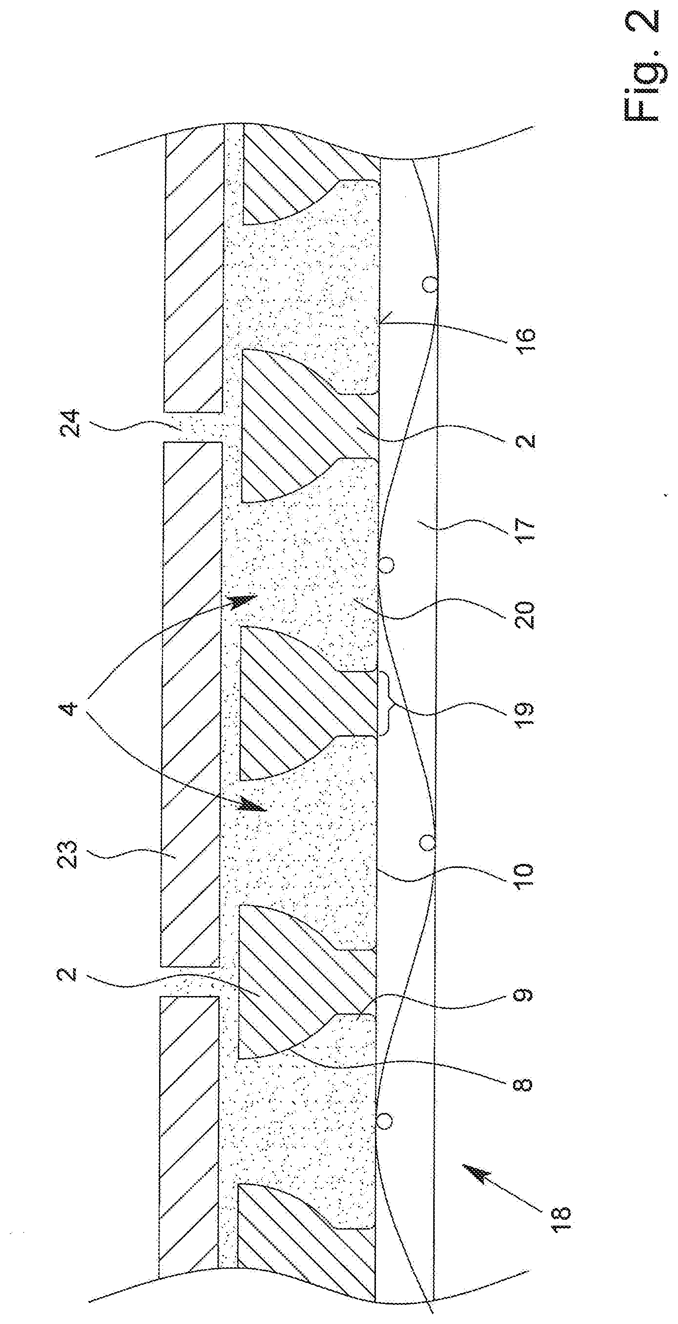
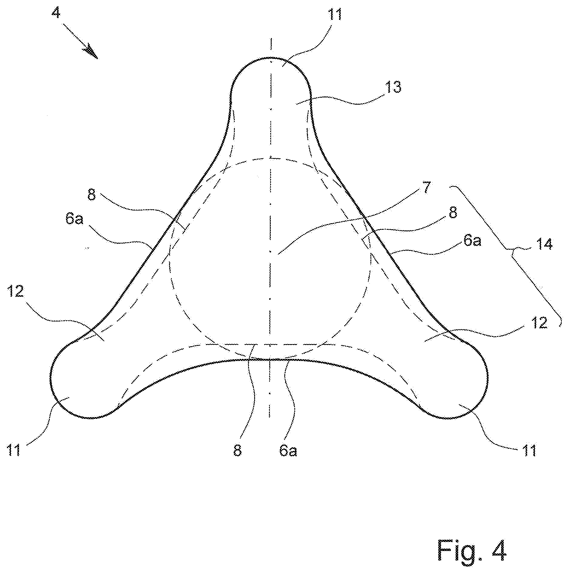
[0055] In one especially advantageous embodiment of the idea of the invention, the shaping to form the undercut on the interior side of the nub is in the form of a sickle and/or an arc segment and/or a crescent. This arc segment formation results in particular in an improved mold stripping during the manufacturing of the decoupling sheet. By contrast with angular undercuts, in the case of a rounded and/or sickle shape of the undercut there is advantageously ensured an easier separation between the molding die and the decoupling sheet. Thus, in particular, the decoupling sheet will not be damaged when stripped from the mold. Moreover, the rounded undercuts preferably serve for reducing the stress peaks of the shear stress of the flooring elements and/or distributing them evenly on the decoupling sheet.
[0056] In another embodiment according to the invention, the shaping is formed by a protrusion protruding from the nub interior space. In an especially advantageous embodiment, the protrusion is provided in the area of the nub base, with the protrusion in particular passing directly into the nub base. This immediate passing of the protrusion into the nub base results in an improved mold stripping, so that the molding die can be removed from the decoupling sheet with no problem, especially even when the state of the decoupling sheet material is not yet completely hardened, with no fear of damaging the decoupling sheet during the mold stripping.
[0057] This advantage also results in particular when the shaping extends for at least 40%, preferably for between 50% and 100% and especially for between 60% and 90% of the length of the long side and/or the leg side. These dimensions mean that the end region of the nub and/or the triaxial nub base formed by two converging long sides is undercut-free and/or has no shaping in this region. In this embodiment, the molding die may have sharp-edged corners in the end region without causing damage to the decoupling sheet during the mold stripping.
[0058] In another embodiment of the idea of the invention, it is provided that the end region of the nub and/or the triaxial nub base formed by two converging long sides is rounded and without corners. In one preferred configuration of the embodiment of the decoupling sheet, the radius of a concave long side is multiple times longer than the radius of an end region, with the radius of a concave long side preferably twice as large as the radius of an end region. Thanks to the concave long sides and the rounded and/or convex end regions of the long sides, a curved nub shape is produced, which significantly reduces and/or in some cases totally prevents stress peaks from arising. These end regions, which in particular are free of undercuts, work against air inclusions and thus make the buttering easier.
[0059] Moreover, it has been established in experiments that were conducted that it is especially advantageous for the nub and/or the triaxial nub base to have mirror symmetry with respect to a center axis running substantially parallel to the lengthwise direction. This mirror-symmetrical nub axis is advantageous not only in terms of manufacturing technology, but also decisively advantageous in regard to the product properties of the decoupling sheet, as shall be discussed in the following.
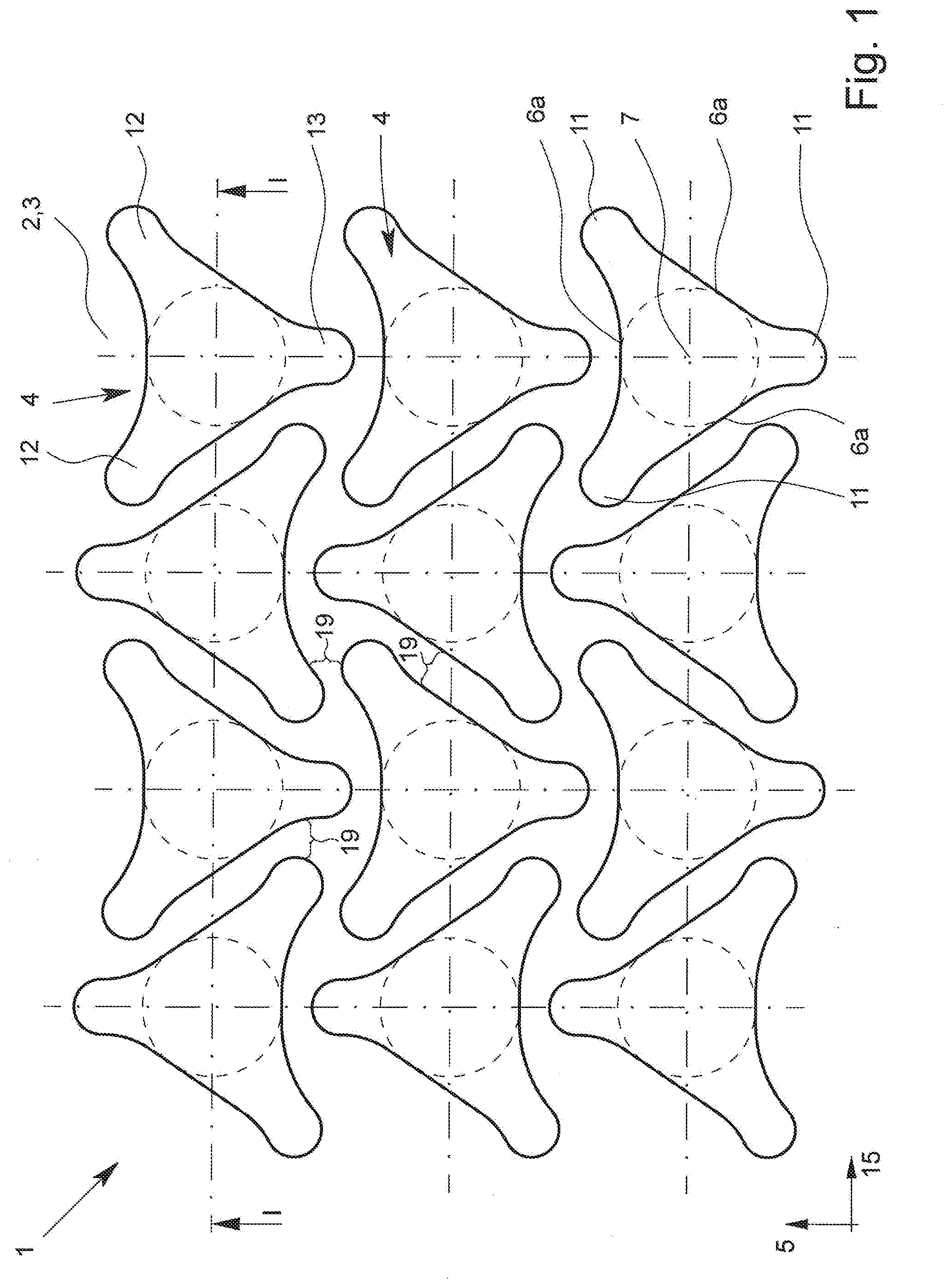
[0060] In another advantageous embodiment of the idea of the invention, it is provided that the angle of the leg emerging from the middle region between the respectively adjacent, spaced-apart leg axes is at least 90.degree..
[0061] In order to ensure an optimized arrangement of the nubs on the decoupling sheet, it is provided in another embodiment according to the invention that the leg length of one leg, especially that of the leg running parallel to the lengthwise direction of the decoupling sheet, is less than the other two leg lengths. It is especially advantageous when the angle situated between the leg axis of the shorter leg and the leg axis of the adjacent leg is greater than 120.degree. and especially less than 130.degree.. Thanks to a preferred mirror-symmetry arrangement, two larger angles are provided for the nub and/or for the triaxial nub base and the angle which is enclosed between the leg axes of the longer legs is accordingly less than 120.degree.. As compared to the usual rectangular and/or rotationally symmetrical geometries customary in the prior art, this geometry affords the benefit in particular of improved decoupling properties of the entire decoupling sheet when using the nub with the aforementioned properties.
[0062] It should be pointed out in this context that especially improved decoupling properties result when there is provided on the decoupling sheet a plurality of nubs according to the invention with the triaxial nub base. In one preferred exemplary embodiment, it is provided that the nubs running transversely to the lengthwise direction of the carrier plate are arranged such that no straight line running transversely to the lengthwise direction of the carrier plate is formed continuously on the carrier plate, and/or nubs running in the lengthwise direction of the carrier plate are arranged such that no straight line running in the lengthwise direction of the carrier plate is formed continuously on the carrier plate, and/or nubs running longitudinally and transversely to the lengthwise direction of the carrier plate are arranged such that no straight line running at a slant to the lengthwise direction of the carrier plate is formed continuously on the carrier plate. The term "continuously" here means a connection from one edge of the decoupling sheet to the opposite edge of the decoupling sheet on the other lengthwise or transverse side of the decoupling sheet. According to the invention, this is accomplished in particular in that a nub having a triaxial nub base with the aforementioned properties is used and thus makes possible this configuration thanks to the arrangement and thus the interaction of the nubs.
[0063] Thanks to the aforementioned configuration, weakening lines and/or predetermined breaking edges of the nub track exceeding the overall nub diameter, especially exceeding it by a multiple, are avoided. The arrangement of the nubs in the aforementioned manner produces channel segments between the nubs which have a trend, especially a meandering trend, in right and left curves, so that the channel segments extend over the carrier plate in a preferably wavy manner. By avoiding a straight trend of the individual channels, one can advantageously prevent the formation of weakening lines running straight across the decoupling sheet. Finally, it is not relevant how the decoupling sheet is installed in a room, so that in any given direction a channel segment running in this direction will come up against a nub if extended in a straight line, so that the weakening line segment formed by the respective channel segment will be interrupted, thus preventing in particular the formation of longer weakening lines. Accordingly, regardless of the orientation of the decoupling sheet during its installation, it can be ensured that the joints formed in the installed floor covering will always extend across nubs for a segment, so that no joints will be congruent with a longer channel segment of the decoupling sheet.
[0064] The carrier plate according to the invention, especially when using the triaxial nub, preferably has only such channels as extend from one side edge to another side edge of the carrier plate and run in right and left curves, relative to the transverse direction of the decoupling sheet and/or the carrier plate. Each space between two adjacent nubs represents a channel segment and is part of a channel, so that weakening lines and/or predetermined breaking edges between spaced-apart nubs running in a straight line across the carrier plate are precluded.
[0065] Finally, it is understood that, in a further embodiment, especially when using a square and/or elliptical and/or rectangular nub, such weakening lines and/or predetermined breaking edges of the decoupling sheet may arise.
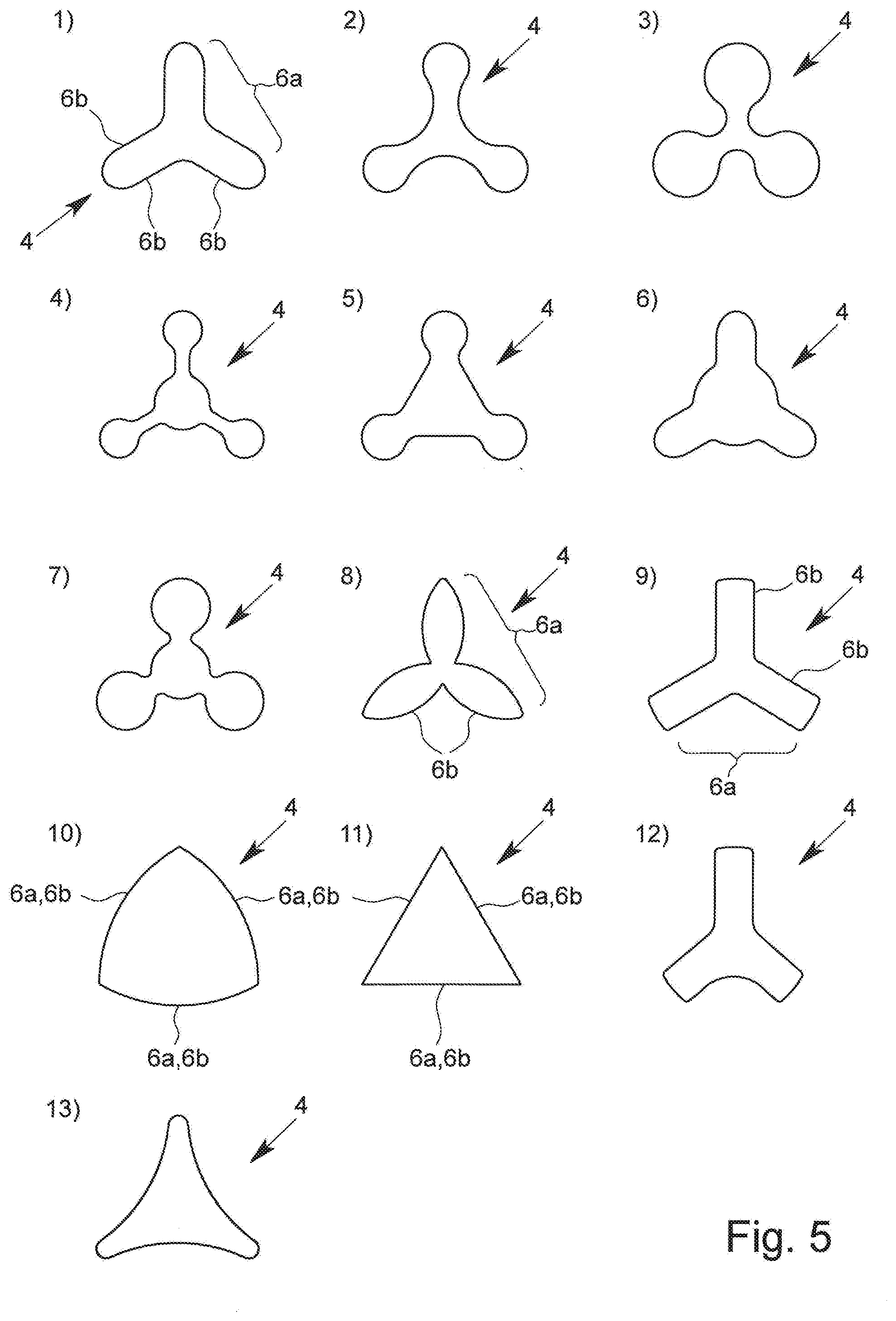
[0066] In another preferred embodiment, the nubs are arranged in rows running in both the lengthwise direction and transverse direction, wherein the center points of the nubs running in the lengthwise direction are arranged on a line running at least substantially parallel to the lengthwise direction of the decoupling sheet and wherein the center points of the nubs running transversely to the lengthwise direction are arranged on a line running at least substantially perpendicular to the lengthwise direction. This arrangement of the nubs results in manufacturing technology benefits, since this preferably symmetrical arrangement of the nubs can be produced by an embossing mechanism, preferably a nub roller, by means of molding dies in a filmlike material which is fed to the embossing mechanism as the base material of the decoupling mat. The molding dies are arranged on the nub roller, so that the embossing of the nubs can occur in a continuous manufacturing process.
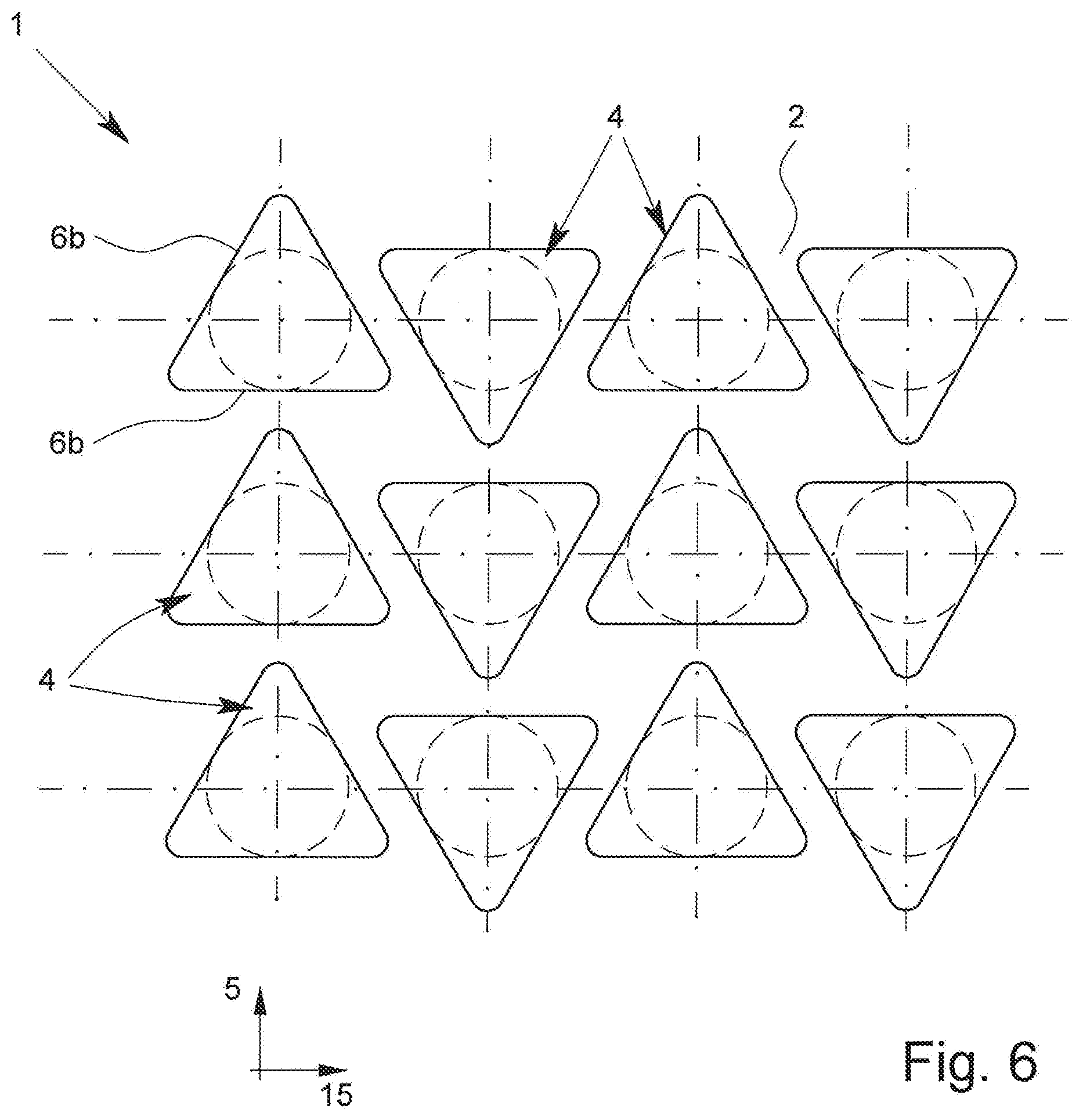
[0067] Another possible and supplemental aspect of the present invention is that the shorter leg of the nubs and/or the nub base arranged in a row of successively arranged nubs running substantially parallel to the lengthwise direction is oriented in the lengthwise direction. In an immediately adjacent row of nubs running at least substantially parallel to the lengthwise direction, the shorter legs of the nubs are oriented opposite to the lengthwise direction. In particular, it is possible in this case to avoid the aforementioned weakening lines across the decoupling sheet by not having the resulting channel segments in a straight line between the adjacent nubs. The shorter legs according to the invention ensure in this case that the nubs are arranged in lengthwise and transverse rows to the carrier plate, yet without having and/or forming a weakening line.
[0068] Preferably, in another embodiment of the idea of the invention, it is provided that the arrangement of the nubs on the carrier plate is embodied such that the shortest distance between two adjacent nubs is always roughly equally large, especially with a deviation of +/-20%, preferably +/-10%. This creates in particular an identical or approximately identical channel width, wherein thanks to the nub shape the channels extend in meandering fashion across the carrier plate. Advantageously, one leg of the nubs is to be configured shorter in order to form identical channel widths and/or to ensure an at least substantially shortest constant segment between two adjacent nubs.
[0069] In another preferred embodiment of the idea of the invention, it is provided that the nubs are arranged and/or configured such that roughly the same flow cross section results in the channels, especially with a deviation of +/-20%, preferably +/-10%.
[0070] Basically, it is understood that a flat connection means can be provided on the outside of the nub bases for connecting between the decoupling sheet and the ground. Preferably, this connection means is fastened to the nub bases, and the connection means is preferably embodied as a nonwoven and/or a textile and/or a scrim and/or a lattice and/or paper, especially formed over the entire surface and/or in a lattice shape. The connection means according to the invention ensures that the nub base is fixedly joined via the connection means to the ground, so that in particular its bond strength is increased. Preferably, the connection means is directly incorporated into the outside of the nub bases during the manufacturing process of the decoupling sheet. Thanks to the fixed connection of the decoupling sheet to the ground by means of the connection means, a shifting between the flooring layer and the decoupling sheet is preferably avoided.
[0071] The arrangement of the connection means on the nub bases is preferably designed so that the channels and/or channel segments are produced between the outsides of the nubs and the connection means, by which a dehumidification and/or a ventilation is possible. The connection means is usually facing toward the ground on which the decoupling sheet is placed. The openings into the individual nubs are oriented toward the installation side, so that the tile adhesive can be placed into the nubs and/or the nub interior spaces.
[0072] In another preferred embodiment of the present invention, the height of the nubs is between 1 and 5 mm, preferably between 2 and 4 mm, further preferably between 2.5 and 3.5 mm. This relatively low nub height enables a low overall layered structure and entails a reduced amount of tile adhesive needed for the bonding between the decoupling sheet and the flooring elements. However, due to the special nub shape and formation, a firm bond is achieved between the tile adhesive and the decoupling sheet while at the same time accomplishing an excellent decoupling effect.
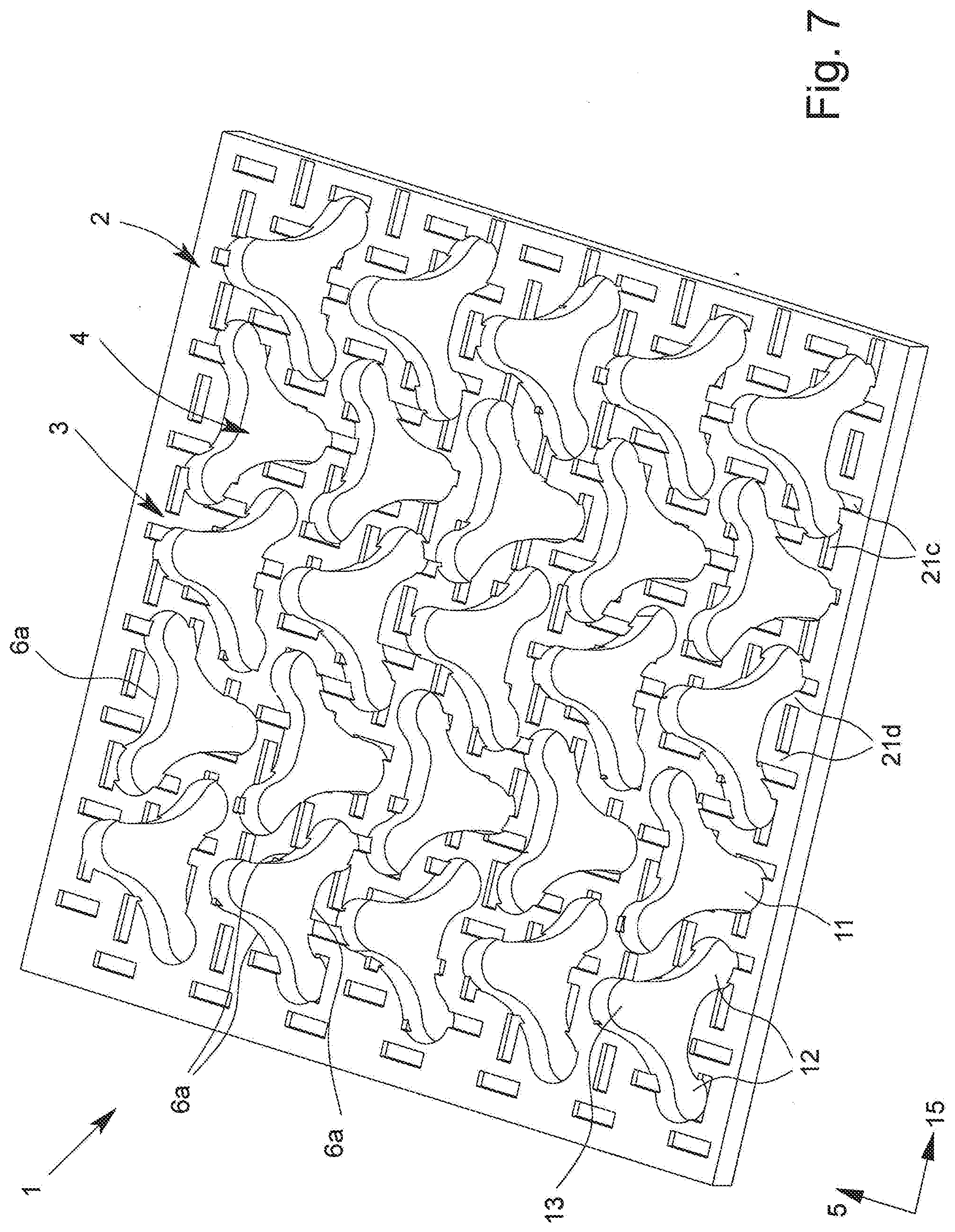
[0073] In another preferred embodiment, the clear gap between adjacent nubs has a width greater than 2 mm, in particular, between 3 mm and 9 mm, preferably between 4 and 8 mm, further preferably between 5 and 6 mm. This clear gap also determines the width of the channel segment and thus defines the free space between adjacent nubs. The channel segment in this case, due to the width which is present, accomplishes not only a good dehumidification and ventilation of the subfloor, but also a uniform heat distribution, especially in system designs with underfloor heating.
[0074] Furthermore, in another preferred embodiment it is provided that the ratio of the area of the nub bases of all the nubs to the carrier plate is preferably between 40% and 70%, further preferably between 45% and 55% and especially at least substantially 50%. It has been established in experiments that were conducted that, by observing the aforementioned ratio, especially good decoupling values are achieved at the same time as an especially firm attachment of the tile adhesive to the decoupling sheet. Along with the nub height, the aforementioned ratio also critically defines the required amount of tile adhesive used for the joining of the decoupling sheet and the flooring element. In particular, a load distribution of the occurring shear stress on the carrier plate is made possible by the channels, wherein preferably a compensation of the occurring stresses is accomplished. Finally, it has been established in experiments that the ratio of 40% to 60%, preferably 45% to 55%, is especially advantageous and has good decoupling properties as well as a good bond strength.
[0075] Furthermore, a method is provided for production of a decoupling sheet having a carrier plate and a plurality of nubs protruding from the carrier plate plane. In the method according to the invention, it is provided that a plurality of protrusions and/or recesses is placed in the side of the nub base of at least one nub facing toward the nub interior space and/or a plurality of protrusions and/or recesses is placed in the side of the carrier plate facing toward the nub interior space, especially wherein the surface is roughened.
[0076] Preferably, therefore, a structured and/or roughened surface is created. The structured surface may comprise protrusions and recesses which are arranged in an irregular and unorganized manner.
[0077] Preferably, the nub bases of immediately adjacent nubs have in particular a triaxial shape transversely to the lengthwise direction and in the lengthwise direction of the carrier plate. Ultimately, however, it is understood that other nub structures may be provided according to the invention.
[0078] In one preferred design of the process according to the invention, it is provided that the protrusion is made by a laser process, a plasma process, a machining process, preferably blasting, especially using sand and/or nutshells, and/or by embossing during and/or after the production of the decoupling sheet. It has been established that the aforementioned processes produce an ideally roughened surface for the later processing of the decoupling sheet.
[0079] Finally, it is understood that the protrusions and/or recesses can be placed into the decoupling sheet and/or the carrier plate and/or the nub base after the production of the decoupling sheet, in particular in a separate step.
[0080] In terms of manufacturing technology, it is convenient to perform the embossing of the protrusions and/or recesses in the decoupling sheet directly during the production of the decoupling sheet, so that the protrusions and/or recesses are positioned directly by means of recesses and/or elevations on the molding dies and/or the embossing mechanism and/or the nub roller.
[0081] In another embodiment, it is provided that the embossing is performed after the production of the decoupling sheet by an additional and/or further embossing roller, one which is heated in particular. This additional embossing roller is adjacent in the production direction to the actual nub roller by which the decoupling sheet per se is created.
[0082] The surface modification or structuring may alternatively be done by mechanical methods, such as blasting, for example when using sand and/or nutshells. A roughening of the surface during mechanical methods can be done by using brushes and/or abrasive paper, for example.
[0083] The drawback to a mechanical roughening by means of sandpaper, brushes and/or a material ablation by means of abrasive paper is the relatively large material ablation, which results in a weakening of the nubs and the decoupling sheet as a whole. Surprisingly, it has been found that the manufacturing methods of laser radiation, plasma radiation, embossing and/or blasting can reduce the material ablation as compared to sandpaper and/or brushes by up to 30%. In particular, the structured surface can be specifically designed and implemented by the production methods according to the invention, which is not possible with brushes and sandpaper.
[0084] The aforementioned methods result in a structured surface and/or a profiling of the surface, so that in particular an increased roughness is produced. The roughening and/or structuring of the surface by means of nutshell blasting has proven to be especially advantageous in the experiments that were conducted.
[0085] In the plasma method, high-energy electrons and ions are generated in particular directly from the surrounding atmosphere by means of strong electric fields and used to generate a plasma. In this way, the surface structure of the decoupling sheet is attacked accordingly. The laser method preferably involves treatment of the surface of the decoupling sheet with a pulsed laser beam source, which can be directed preferably with high beam intensity onto the surface of the decoupling sheet.
[0086] When installing the decoupling mat on an ground, a bond-strengthening layer can be placed between the decoupling sheet and the flooring elements, preferably by spreading and/or spraying and/or brushing it onto the decoupling sheet. Basically, it is also conceivable to apply a bond-strengthening layer to the decoupling sheet by spreading and/or spraying and/or brushing it on already during the manufacturing of the decoupling sheet.
[0087] Hence, the invention relates to a decoupling sheet with a carrier plate and a plurality of nubs protruding from the carrier plate, wherein adjacent nubs are arranged transversely to the lengthwise direction of the carrier plate and in the lengthwise direction of the carrier plate, wherein to improve the decoupling properties and to increase the bond strength a plurality of protrusions and/or recesses is provided on the nub bases and/or the surface of the carrier plate facing away from the nub bases. Finally, the invention also relates to a method for production of a decoupling sheet, especially one having the protrusions and/or recesses according to the invention.
[0088] Moreover, it is understood that the aforementioned intervals and range limits include any intermediate intervals and individual values and are to be seen as being disclosed as essential to the invention, even if these intermediate intervals and individual values are not specifically indicated.
BRIEF DESCRIPTION OF THE DRAWINGS
[0089] Further features, benefits and application possibilities of the present invention will emerge from the following description of exemplary embodiments with the aid of the drawing, and from the drawing itself. All of the described and/or depicted features in themselves or in any given combination form the subject matter of the present invention, regardless of their statement in the claims or their reference back to the claims.
[0090] FIG. 1 shows a schematic top view of a portion of a decoupling sheet,
[0091] FIG. 2 shows a schematic cross sectional view along line I-I of FIG. 1,
[0092] FIG. 3 shows a schematic top view of a nub having a triaxial nub base,
[0093] FIG. 4 shows a schematic top view of another embodiment of a nub,
[0094] FIG. 5 shows schematic top views of further nubs having a triaxial nub base,
[0095] FIG. 6 shows a schematic top view of another variant embodiment of a decoupling sheet,
[0096] FIG. 7 shows a perspective schematic view of one embodiment of a decoupling sheet according to the invention,
[0097] FIG. 8 shows a perspective schematic view of another embodiment of a decoupling sheet according to the invention,
[0098] FIG. 9 shows a perspective schematic view of another embodiment of a decoupling sheet according to the invention,
[0099] FIG. 10 shows a perspective schematic view of another embodiment of a decoupling sheet according to the invention,
[0100] FIG. 11 shows a perspective schematic view of another embodiment of a decoupling sheet according to the invention,
[0101] FIG. 12 shows a perspective schematic view of another embodiment of a decoupling sheet according to the invention,
[0102] FIG. 13 shows a schematic cross sectional view of a decoupling sheet according to the invention along line II-II of FIG. 11,
[0103] FIG. 14 shows a schematic top view of another variant embodiment of a decoupling sheet,
[0104] FIG. 15 shows a perspective schematic view of another embodiment of a decoupling sheet according to the invention,
[0105] FIG. 16 shows a perspective schematic view of another embodiment of a decoupling sheet according to the invention,
[0106] FIG. 17 shows a perspective schematic view of another embodiment of a decoupling sheet according to the invention, and
[0107] FIG. 18 shows a schematic cross sectional view of a decoupling sheet according to the invention per FIG. 17.
DETAILED DESCRIPTION
[0108] FIG. 1 shows a portion of a decoupling sheet 1 with a carrier plate 2 and a plurality of nubs 4 protruding from the carrier plate plane 3. Adjacent nubs 4 are arranged transversely to the lengthwise direction 5 (in the transverse direction 15) of the carrier plate 2 and in the lengthwise direction 5 of the carrier plate 2. Furthermore, FIG. 1 illustrates that immediately adjacent nubs 4 transversely to the lengthwise direction 5 (in the transverse direction 15) and in the lengthwise direction 5 of the carrier plate 2 have a triaxial nub base 10.
[0109] FIG. 14 shows that other shapes and/or structures can also be provided for the nub 4 in other variant embodiments. FIG. 14 illustrates that an elliptical, especially a cylindrical nub 4, and a diamond-shaped nub 4 are provided on a decoupling sheet 1. Finally, it is understood that only cylindrical and/or only diamond-shaped and/or only rectangular nubs 4 are present in other variant embodiments on the decoupling sheet 1. However, it is not shown in FIG. 14 that the decoupling sheet 1 comprises protrusions 21a, 21c and/or recesses 21b, 21d. These protrusions 21a, 21c and/or recesses 21b, 21d may have different shapes and structures in other variant embodiments (not shown), in particular forming a structured surface of the nub base 10 and/or the carrier plate 2. Moreover, it is not shown that the protrusions 21a, 21c and/or recesses 21b, 21d may be present on decoupling sheets 1 together with different shapes of the nub 4. Further, it is not shown that the nub 4 may have multiple legs, wherein it may have two or more legs. In the variant embodiments of FIGS. 1 to 13, the three-legged shape of the nub 4 and/or the nub base 10 is provided.
[0110] The triaxial formation of the nub 4 and/or the nub base 10 means that three legs 12, 13 are provided. The triaxial formation of the nub base 10 is evident in the top view looking down on the decoupling sheet 1 and hence in a top view looking down on the nub 4. The immediate proximity of the nubs 4 in the lengthwise direction 5 and in the transverse direction 15 occurs in the case of a group of at least three nubs 4. This means that at least three immediately adjacent nubs 4 comprise a triaxially shaped nub base 10 in the lengthwise direction 5 and in the transverse direction 15. In the arrangement of the nubs 4 on the carrier plate 2 it is provided that the nubs 4 and the nub bases 10 neither intersect nor overlap. Finally, it is understood that in an embodiment of the decoupling sheet 1 according to the invention (not shown), it may be provided that different nub shapes and/or forms of the nub base 10 both triaxial and any given shapes may be used on the decoupling sheet 1. In this variant embodiment (not shown), a group of at least three immediately adjacent nubs 4 with a triaxial nub base 10 is preferably formed.
[0111] Alternatively and/or additionally to the triaxial formation of immediately adjacent nubs 4 in the lengthwise direction 5 and in the transverse direction 15, it is provided that at least one nub 4 having a triaxial nub base 10 with three long sides 6a is present on the decoupling sheet 1. FIGS. 3 and 4 show that the middle region 7 of the nub 4 and/or the nub base 10 is defined by a circle which all the long sides 6 contact tangentially.
[0112] FIGS. 3 and 4 show various embodiments of the triaxial nub shape with different triaxial nub bases 10 having three long sides 6a.
[0113] Moreover, FIG. 1 shows the arrangement of the nubs 4 per FIG. 4 on a decoupling sheet 1, wherein all the nubs 4 have a triaxial nub base 10.
[0114] In a variant embodiment (not shown), only one nub shape having a triaxial nub base 10 with three long sides 6a per FIG. 3 or 4 is provided and placed in a carrier plate 2, with the other nubs 4 having familiar nub structures, such as cylindrical and/or pot-shaped.
[0115] Moreover, FIGS. 3 and 4 show that the long side 6 of the nub 4 and/or the nub base 10 is concave. In a variant embodiment (not shown), only one long side 6a of the nub 4 or two long sides 6a of the nub 4 are concave.
[0116] A nub interior space 20 is formed by the nub base 10 and at least one side wall adjoining the nub base 10, wherein the at least one side wall produces the three-dimensional shape of the nub 4.
[0117] FIG. 2 shows that in the exemplary embodiment illustrated, an undercut 8 is present at the nub interior side. This nub interior undercut 8 is formed by the shaping 8, wherein the shaping 8 in the exemplary embodiment shown is sickle-shaped and/or shaped as an arc segment and/or as a crescent. The shaping 8 is furthermore formed by a protrusion 9 sticking out from the nub interior space 20. The shaping 8 in FIGS. 3 and 4 is provided in the area of the long side 6a of the nub 4. It is clear with the aid of FIG. 2 that the protrusion 9 in the exemplary embodiment shown is arranged in the area of the nub base 10 and passes into the nub base 10. Moreover, FIGS. 3 and 4 show that the shaping 8 extends for around 90% of the long side 6a. In an embodiment (not shown), it is provided that the shaping 8 extends for at least 40%, preferably in further embodiments between 50 and 100% and especially between 60 and 90%, of the long side 6a.
[0118] Further, FIGS. 3 and 4 show that the end region 11 produced by two converging long to sides 6a is undercut-free and thus has neither an undercut 8 nor a protrusion 9 to form the undercut 8. In addition, in the exemplary embodiment shown, the resulting end region 11 is rounded and formed without corners, with the rounding being described by means of a circular arc segment. The radius characterizing the concavity of the long side 6a is multiple times larger than the radius determining the circular arc segment of the end region 11.
[0119] In addition, FIGS. 3 and 4 show that the nub 4 and/or the triaxial nub base 10 has mirror symmetry with respect to a center axis running at least substantially parallel to the lengthwise direction 5. This mirror symmetry is also clearly shown by FIG. 1. In the triaxial nub shape of the nub base 10 per FIGS. 3 and 4, three legs 12, 13 are provided spaced apart from each other and emerging from the middle region 7.
[0120] FIGS. 3 and 4 make it clear that a leg length 14 of one leg 13 running parallel to the center axis is shorter than the other two leg lengths 14 of the leg 12. Furthermore, in the exemplary embodiment shown, different angles of the leg axes are also provided. Basically, in all nub shapes shown for the nub 4, angles between two adjacent leg axes greater than 90.degree. are provided. In the configuration of the nub 4 according to the invention in FIGS. 3 and 4, it is provided that the angle of the leg axis of the shorter leg 13 with respect to the leg axis of the adjacent leg 12 is greater than 120.degree., being around 123.degree. in the exemplary embodiment shown. Consequently, the angle between the leg axes of the legs 12 is less than 120.degree., around 114.degree..
[0121] The configuration of the nub 4 with a triaxial nub base 10 makes possible the nub arrangement of FIG. 1. In this exemplary embodiment, it is provided that the nubs 4 running transversely to the lengthwise direction 5 of the carrier plate 2 are arranged such that no continuous straight line running transversely to the lengthwise direction 5 of the carrier plate 2 and thus in the transverse direction 15 of the carrier plate 2 is formed on the carrier plate 2 and/or the carrier plate plane 3. Furthermore, it is also provided that the nubs 4 running in the lengthwise direction 5 of the carrier plate 2 are arranged such that no continuous straight line running in the lengthwise direction 5 of the carrier plate 2 is formed on the carrier plate 2. However, not only are straight lines avoided in the lengthwise direction 5 and in the transverse direction 15, but also the nubs 4 running longitudinally and transversely to the lengthwise direction 5 of the carrier plate 2 are arranged such that no continuous straight line running at a slant to the lengthwise direction 5 of the carrier plate 2 is formed on the carrier plate 2. Consequently, no straight line is produced on the decoupling sheet 1, since respective individual line segments are interrupted by the nubs 4. The channel segment with the clear gap 19 occurring between two nubs 4 is arranged such that it extends in a meandering manner per FIG. 1 across the decoupling sheet 1. The lines possibly produced in the channel segment cannot continue in a straight line across the carrier plate 2. In each case, a leg 12, 13 of an adjacent nub 4 protrudes into the channel segment between two nubs 4.
[0122] Furthermore, it is understood that this can also be realized when using a different nub shape. Other triaxial nub shapes of the nub base 10 of the nub 4 are represented by FIG. 5 and denoted as variant embodiments 1 to 13. The arrangement of these possible nub shapes on the carrier plate 2 can be embodied such that the aforementioned continuous straight lines do not occur on the carrier plate 2. The triaxial embodiments 1 to 13 of FIG. 5 each exhibit at least three leg sides 6b, whereby it is understood that the long side 6a is formed by at least one leg side. It is not shown that the variant embodiments 1 to 13 may have an undercut 8 in the area of the long side and/or that the shaping 8 may extend for at least 40% of the long side 6a and/or along the leg side 6b.
[0123] FIG. 6 shows that, when using a triangular nub shape for the nub base 10 of the nub 4, an arrangement on the carrier plate 2 is provided such that no continuous straight line of the channel segment of adjacent nubs 4 results on the carrier plate 2. The center points of the nubs 4 and/or the nub bases 10 per FIG. 3 are arranged on straight lines running parallel to the lengthwise direction 5 and on lines running parallel to the transverse direction 15.
[0124] Also in the triaxial configuration of the nub base 10 in FIGS. 3 and 4, these nubs 4 are arranged on the carrier plate 2 such that an arrangement per FIG. 1 is produced, wherein the nubs 4 are arranged running in rows in the lengthwise direction 5 and in the transverse direction 15. The center points of the nubs 4 running in the lengthwise direction 5 are arranged on a line running at least substantially parallel to the lengthwise direction 5. In addition, the center points of the nubs 4 running transversely to the lengthwise direction 5 are arranged on a line running at least substantially perpendicular to to the lengthwise direction 5 and thus in the transverse direction 15. This arrangement of the nubs 4 produces a symmetrical series of nubs within the respective row, wherein this arrangement in particular makes it possible for the aforementioned continuous straight lines and/or weakening lines not to occur on the carrier plate 2.
[0125] However, not only are the center points of the nubs 4 and/or the nub bases 10 arranged in rows on the decoupling sheet 1 of FIG. 1, but also the arrangement is such that the nubs 4 arranged in succession in a row running at least substantially parallel to the lengthwise direction 5 extend in such a way that the shorter leg 13 of the nubs 4 is oriented in the lengthwise direction 5. In an immediately adjacent row running at least substantially parallel to the lengthwise direction 5, the nubs 4 arranged in succession are oriented such that the shorter leg 13 of the nubs 4 is oriented opposite to the lengthwise direction 5. This produces an alternating nub orientation in a row running at least substantially parallel to the transverse direction 15.
[0126] For the arrangement of the decoupling sheet 1 on an ground 18, a connection means 17 is provided per FIG. 2. This connection means 17 is placed on the outside 16 of the nub bases 10. In the exemplary embodiment shown, the connection means 17 is secured to the outside 16 of the nub bases 10. A nonwoven has been used as the connection means 17 in the exemplary embodiment shown. It is understood that in further variant embodiments (not shown), one could also use a textile and/or paper and/or a scrim and/or a lattice. The connection means 17 is provided with a lattice-like configuration in the exemplary embodiment shown. In an embodiment (not shown), besides the lattice-like formation, a formation is also possible over the entire surface.
[0127] Furthermore, the nub 4 of FIG. 2 has a height of 3 mm. In further embodiments, which are not shown graphically, a height between 1 and 4 mm, further preferably between 2.5 and 3.5 mm, is provided. Further, the clear gap 19 between adjacent nubs 4 in the exemplary embodiment shown is greater than 2 mm. The clear gap 19 between the nubs 4 varies on the decoupling sheet 1 of FIG. 1, so that a clear gap 19 between roughly 3 mm and 9 mm can be provided, preferably between 4 and 8 mm, further preferably between 5 and 6 mm. Moreover, FIG. 1 shows that the ratio between the area of the nub bases 10 of all the nubs 4 and the area of the carrier plate 2 is at least substantially around 50%. In further embodiments, the ratio can be between 40% and 70%, preferably between 45% and 55%.
[0128] Moreover, FIG. 2 shows that tiles 23 are provided on top of the carrier plate 2. Joints 24 result between adjacent tiles 23. For connecting the tiles 23 to the decoupling sheet 1, a tile adhesive is provided, which is applied both in the nub interior space 20 and on the carrier plate 2. This catches inside the undercut 8 and/or penetrates into the protrusion 9. Regardless of the orientation of the decoupling sheet 1 on an ground 18, the joints 24 between the tiles 23 do not coincide with a weakening line and/or a continuous line on the carrier plate 2. The possible continuous line produced between two nubs 4 cannot continue across adjacent nubs 4.
[0129] In further exemplary embodiments per FIGS. 7 to 13, it is provided that protrusions 21a, 21c and/or recesses 21b, 21d may be present both on the nub base 10 and on the carrier plate 2. It is understood that recesses 21b, 21d are respectively provided between adjacent protrusions 21a, 21c. Ultimately, basically one recess is adjacent to a protrusion 21a, 21c and/or recess 21b, 21d.
[0130] FIGS. 7 to 12 show a carrier plate 2 and nubs 4, wherein the nub interior space 20 is open toward the carrier plate 2. The protrusions 21a and/or recesses 21b may be provided on the side of the nub base 10 facing toward the nub interior space 20 in FIGS. 9 to 11. In the exemplary embodiments shown, the protrusions 21a in FIGS. 9 to 11 are provided on all nub bases 10 shown for the decoupling sheet 1.
[0131] A perforation of the carrier plate 2 with the protrusions 21c and/or recesses 21d is shown in the exemplary embodiment of FIGS. 7 to 8 and FIGS. 11 to 12. The protrusions 21c here are provided on the side facing toward the nub interior space 20. Accordingly, recesses are provided on the side of the carrier plate 2 facing away from the nub interior space 20 and/or the nub base 10, corresponding to the protrusions 21c. Finally, it is understood that a recess 21d may be provided next to each protrusion 21c on the side of the carrier plate 2 facing toward the nub interior space 20.
[0132] In the exemplary embodiments, a plurality of protrusions 21c is provided on the carrier plate 2.
[0133] The exemplary embodiments show that more than 20, preferably more than 100, protrusions 21a, 21c and/or recesses 21b, 21d are provided. In further embodiments, further preferably more than 1000, preferably more than 10000 protrusions 21a, 21c and/or recesses 21b, 21d are provided.
[0134] FIGS. 15 to 17 show schematically that the protrusions 21a, 21c and/or recesses 21b, 21d are arranged in an irregular and/or unordered manner, preferably on both the nub base 10 and the carrier plate 2. FIG. 15 shows schematically a structured surface of the carrier plate 2, which is created by irregular and at least partly unequal protrusions 21a, 21c and/or recesses 21b, 21d. FIG. 16 shows a structuring of the nub base 10 wherein the surface of the nub base 10 has been roughened. Finally, FIG. 17 schematically shows a structured surface of the nub base 10 and the carrier plate 2, where all the nub bases 10 shown are structured and the structuring extends over the entire surface of the carrier plate 2.
[0135] The protrusions 21a, 21c and the recesses 21b, 21d are shown schematically in FIGS. 15 to 18, since the structuring of the nub base 10 and/or the carrier plate 2 is in part hardly noticeable by the naked eye on account of the relatively short height of the protrusions 21a, 21c and the recesses 21b, 21d of around 500+/-300 .mu.m.
[0136] The roughened surface of the carrier plate 2 and the nub base 10 in FIGS. 15 to 18 is accordingly shown schematically and extends preferably over the full surface of the nub bases 10 and/or the carrier plates 2.
[0137] FIGS. 15 to 18 schematically show that the protrusions 21a, 21c and the recesses 21b, 21d produce a structured and roughened surface wherein the protrusions 21a, 21c and the recesses 21b, 21d are arranged irregularly. In FIGS. 15 to 17, nubs 4 with a triaxial nub base 10 are shown exclusively. It is not shown that the decoupling sheet 1 may have an irregular structuring of the carrier plate 2 and/or the nub bases 10 with different nub shapes, such as cylindrical or cuboidal nubs 4.
[0138] FIG. 18 schematically shows a cross section along the decoupling sheet 1 represented in FIG. 17. The decoupling sheet 1 is irregularly structured on the nub base 10 and on the surface of the carrier plate and accordingly comprises protrusions 21a, 21c and/or recesses 21b, 21d. The recesses 21b on the nub base 10 are arranged on a connection means 17, while the tile adhesive for the connecting of the tiles 23 to the decoupling sheet 1 and/or the carrier plate 2 penetrates into the protrusions 21c of the carrier plate 2 and/or into the recesses 21b of the nub 4.
[0139] The protrusions 21a, 21c and/or recesses 21b, 21d may take on various geometrical shapes and structures. For example, several of the depicted embodiments shall be explained in the following. It is understood here that different protrusions 21a, 21c with different structures may be provided according to the invention in other embodiments (not shown). Ultimately, it is decisive for the protrusions 21c and/or recesses 21b that the tile adhesive for connecting the tiles 23 to the decoupling sheet 1 can penetrate into the protrusions 21c and/or recesses 21b and fill them up completely. This is illustrated with the aid of FIG. 13.
[0140] In the embodiments shown, a multitude and/or plurality of protrusions 21a, 21c and/or recesses 21b, 21d is provided either on the carrier plate 2 or on the nub base 10 or on both. The protrusion 21a on the nub base 10 is formed in the shape of a spiral and/or an arc segment according to FIGS. 9 and 11. This trend in the shape of a spiral of the protrusion 21a emerges from the middle region 7 of the nub base 10. A multitude of protrusions 21a per FIG. 10 may be provided not only on the nub base 10 itself, but also on the leg bottom 22 of a leg 12, 13.
[0141] Ultimately the protrusions 21a, 21c and/or recesses 21b, 21d act to produce a structured surface of the nub base 10 and/or carrier plate 2.
[0142] In FIG. 8, the protrusions 21c of the carrier plate 2 have a shaping designed to create an undercut. In a further embodiment not shown, it is provided that the protrusions 21a and/or the recesses 21b of the nub base 10 also have a shaping to create an undercut.
[0143] Moreover, in another embodiment (not shown), it is provided that the protrusions 21a, 21c and/or the recesses 21b, 21d have a height and/or a depth greater than 1 .mu.m, preferably greater than 100 .mu.m, further preferably between 100 and 1000 .mu.m and especially between 300 and 500 .mu.m.
[0144] Ultimately, it is understood that the protrusions 21a and/or recesses 21b of the nub base 10 may also pass directly into the protrusions 21c and/or recess 21d of the carrier plate 2, wherein in particular the structure and/or shape of the protrusions 21a, 21c and/or the recesses 21b, 21d can be interrupted when the carrier plate 2 has a recess on account of the nub 4 and/or when the carrier plate 2 passes into the nub 4. It is also understood that the protrusions 21a and/or the recesses 21b on the nub base 10 interrupt its geometrical structure, especially when the nub wall of the nub 4 passes into the protrusion 21a and/or the recess 21b of the nub base 10.
[0145] FIG. 9 shows that protrusions 21a in the shape of an arc segment are provided on the leg bottom 22 concentrically to the middle region 7 around the center point of the nub 4 and/or the nub base 10.
[0146] FIG. 10 shows a further geometrical shape of the protrusions 21a, wherein the protrusions 21a are formed on the nub base 10 as webs and/or at least as substantially rectangular and/or elliptical in shape. The web-like and/or at least substantially rectangular and/or elliptical protrusions 21a on the nub base 10 of FIG. 10 are provided transversely and/or longitudinally to the lengthwise direction 5 of the carrier plate 2.
[0147] In addition, FIG. 7 shows that a plurality of protrusions 21c and/or recesses 21d is present on the carrier plate 2 in the exemplary embodiment shown, wherein the protrusions 21c are arranged in rows running transversely to the lengthwise direction 5 of the carrier plate 2. FIG. 7 represents web-like and/or rectangular protrusions 21c on the carrier plate 2. The elongated protrusions 21c shown in FIG. 7 extend with their lengthwise dimension solely transversely and/or longitudinally to the lengthwise direction 5 of the carrier plate 2. The protrusions 21c in the exemplary embodiment of FIG. 7 are arranged in a row with alternating orientation, running longitudinally and/or transversely to the lengthwise direction 5 of the carrier plate 2.
[0148] FIG. 8 shows that the protrusions 21c are rectangular in shape. In an embodiment (not shown), the protrusions 21c of the carrier plate 2 are elliptical in shape. It is understood that ultimately recesses 21d may also have the geometrical shapes of the protrusions 21c.
[0149] FIG. 13 shows a cross sectional view along section II-II of FIG. 11, showing that the recesses 21b are arranged on the nub base 10 on a connection means 17, wherein the tile adhesive for connecting the tiles 23 to the decoupling sheet 1 and/or the carrier plate 2 penetrates into the protrusions 21c of the carrier plate 2 and/or into the recesses 21b of the nub 4.
[0150] Moreover, a method is also provided for the production of a decoupling sheet 1 in the exemplary embodiment shown, wherein the decoupling sheet 1 comprises a carrier plate 2 and a plurality of nubs 4 protruding from the carrier plate 2, wherein adjacent nubs 4 are provided transversely to the lengthwise direction 5 of the carrier plate 2 and in the lengthwise direction 5 of the carrier plate 2 per FIG. 1 and per FIGS. 6 to 12. It is provided, according to the embodiment shown, that the nub bases 10 of immediately adjacent nubs 4 are triaxial in shape and a plurality of protrusions 21a and/or recesses 21b is placed in the side of the nub base 10 of at least one nub 4 facing toward the nub interior space 20 and/or a plurality of protrusions 21c and/or recesses 21d is placed in the side of the carrier plate 2 facing toward the nub interior space 20. The protrusions 21a, 21c placed into the nub base 10 and/or the carrier plate 2 is illustrated by FIGS. 7 to 12. However, it is understood that in other embodiments (not shown) a different structure other than the triaxial formation of the nub base 10 of the nub 4 may be chosen within the method for production of a decoupling sheet 1.
[0151] In an embodiment (not shown), it is provided that the protrusions 21a, 21c and/or recesses 21b, 21d are made by a laser process, a plasma process, a machining process, preferably blasting, especially using sand and/or nutshells, and/or by embossing during and/or after the production of the decoupling sheet 1, wherein the protrusion 21a, 21c and/or the recess 21b, 21d is incorporated into the carrier plate 2 and/or into the nub 4 on the nub base 10.
LIST OF REFERENCE NUMBERS
[0152] 1 Decoupling sheet [0153] 2 Carrier plate [0154] 3 Carrier plate plane [0155] 4 Nubs [0156] 5 Lengthwise direction [0157] 6a Long side of nub [0158] 6b Leg side of nub [0159] 7 Middle region [0160] 8 Undercut/shaping [0161] 9 Protrusion to form the undercut [0162] 10 Nub base [0163] 11 End region [0164] 12 Leg [0165] 13 Short leg [0166] 14 Leg length [0167] 15 Transverse direction [0168] 16 Outside of nub base [0169] 17 Connection means [0170] 18 Ground [0171] 19 Clear gap [0172] 20 Nub interior space [0173] 21a Protrusion of nub [0174] 21b Recess of nub [0175] 21c Protrusion of carrier plate [0176] 21d Recess of carrier plate [0177] 22 Leg bottom [0178] 23 Tile [0179] 24 Joint
* * * * *
D00000
D00001
D00002
D00003
D00004
D00005
D00006
D00007
D00008
D00009
D00010
D00011
D00012
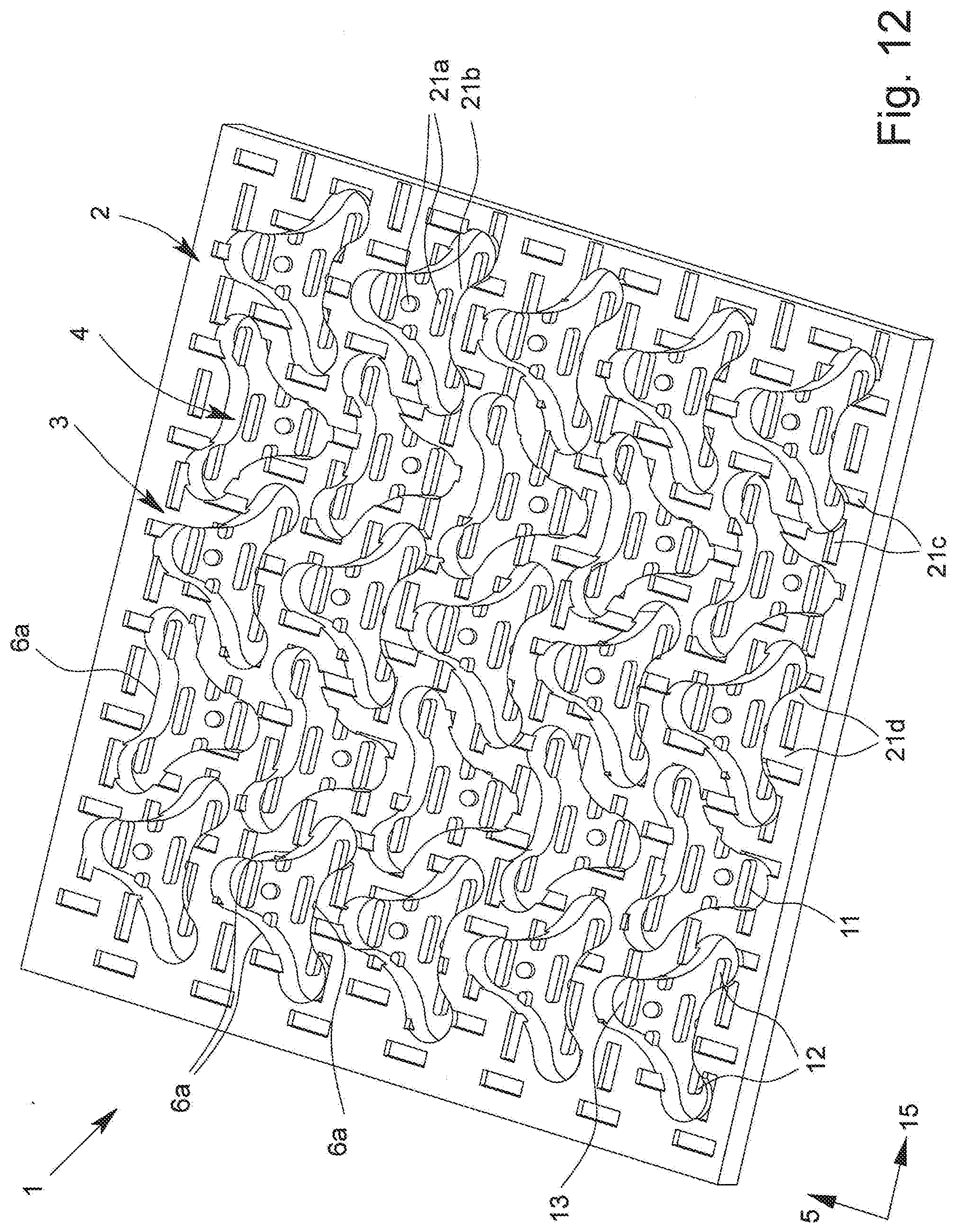
D00013
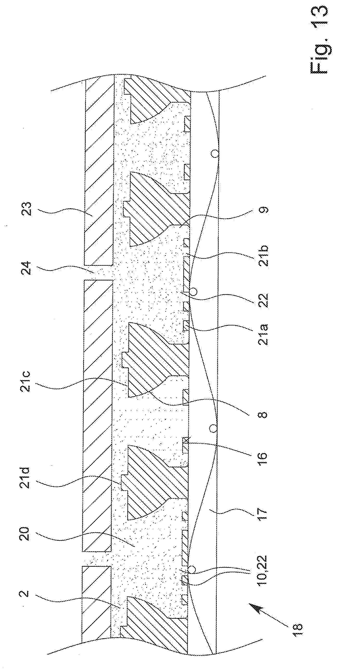
D00014
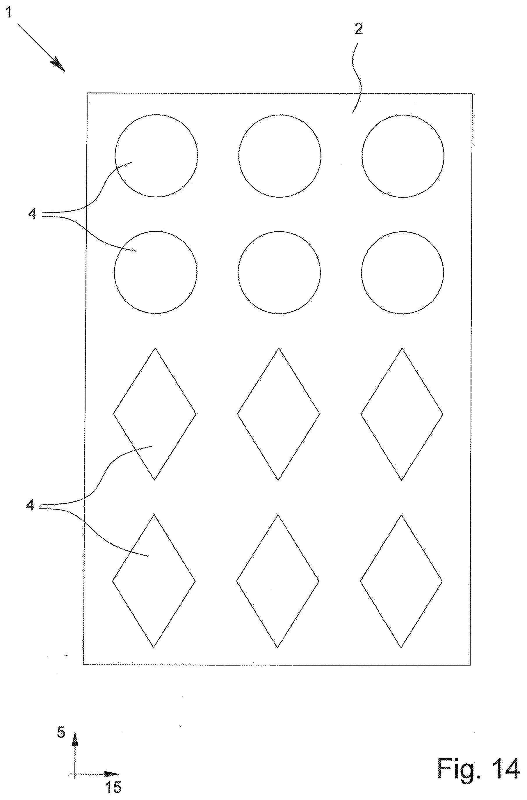
D00015
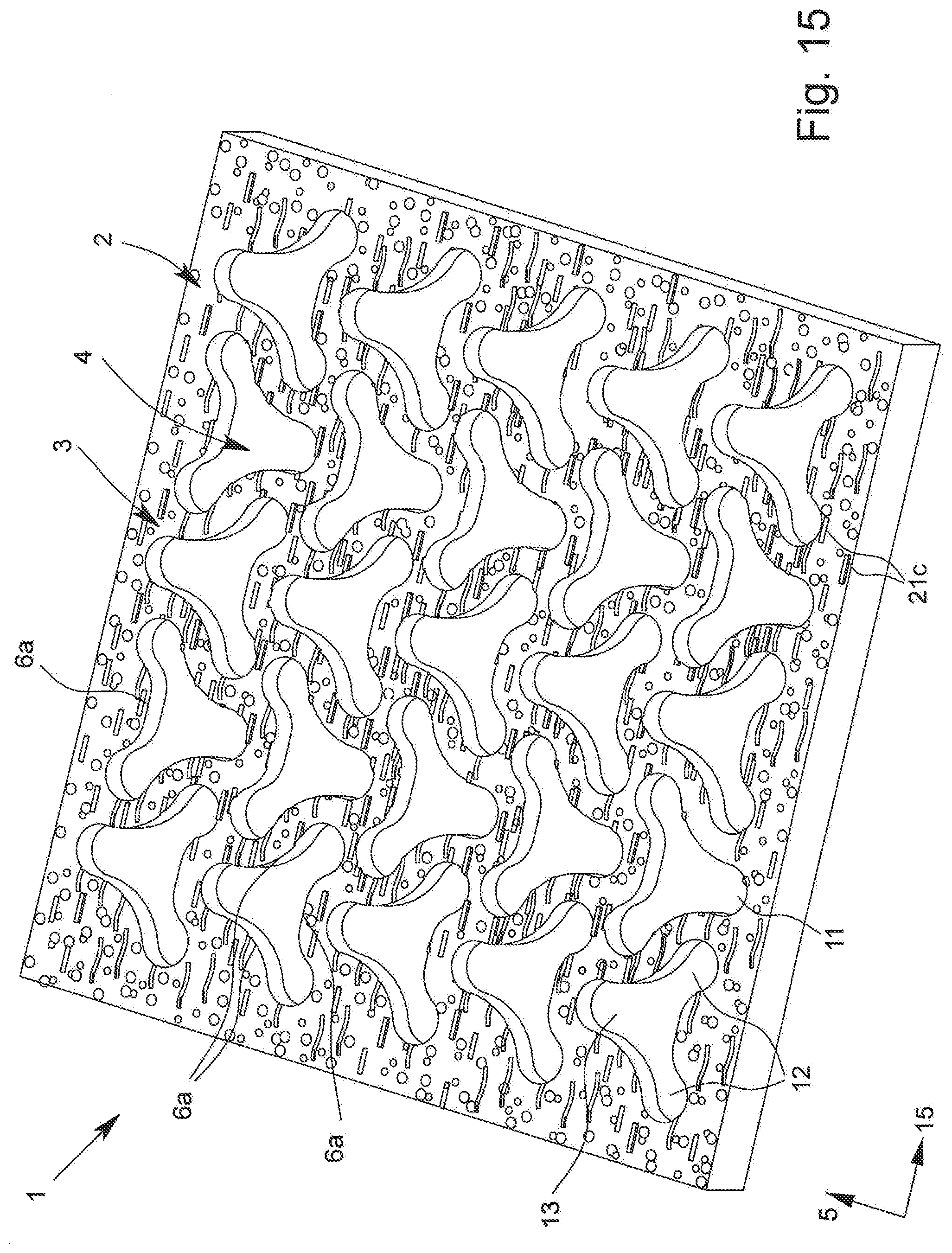
D00016
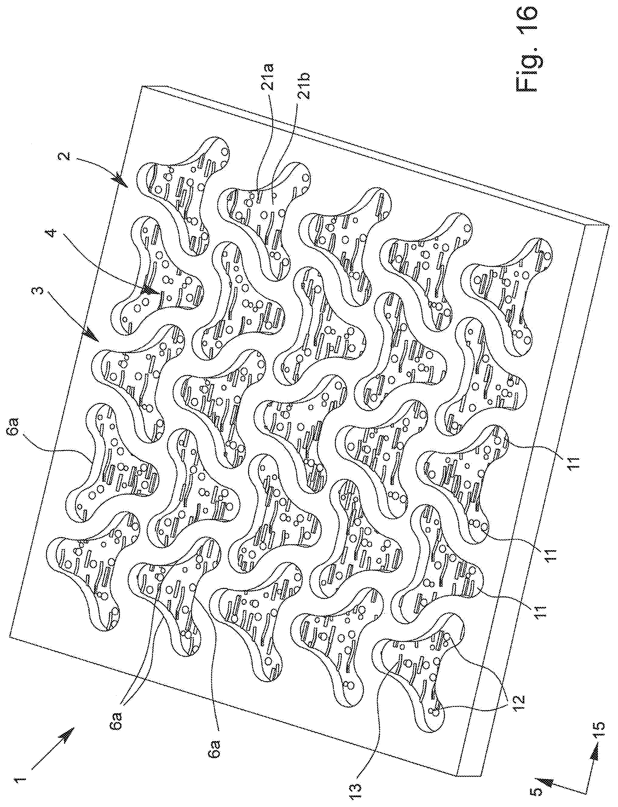
D00017
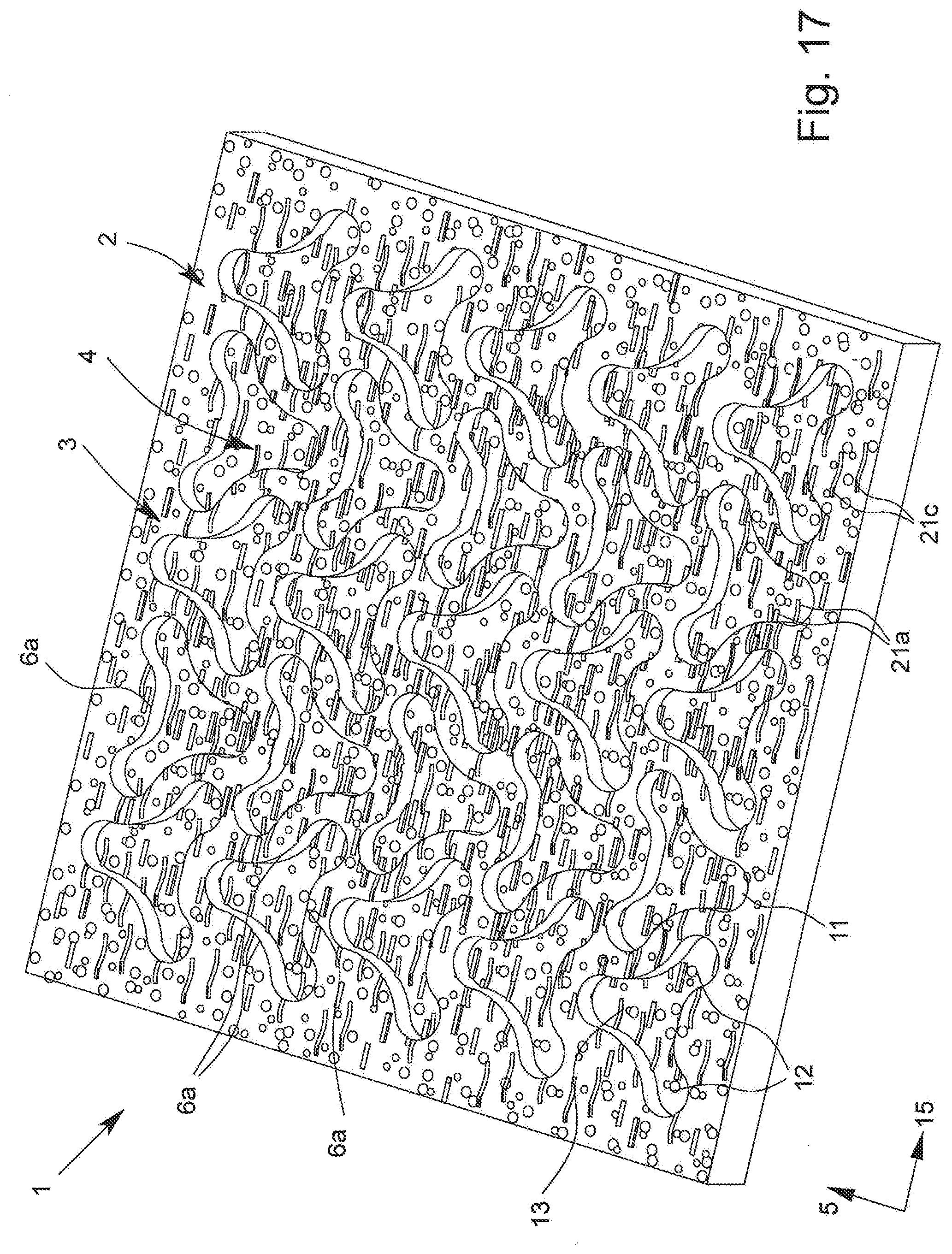
D00018
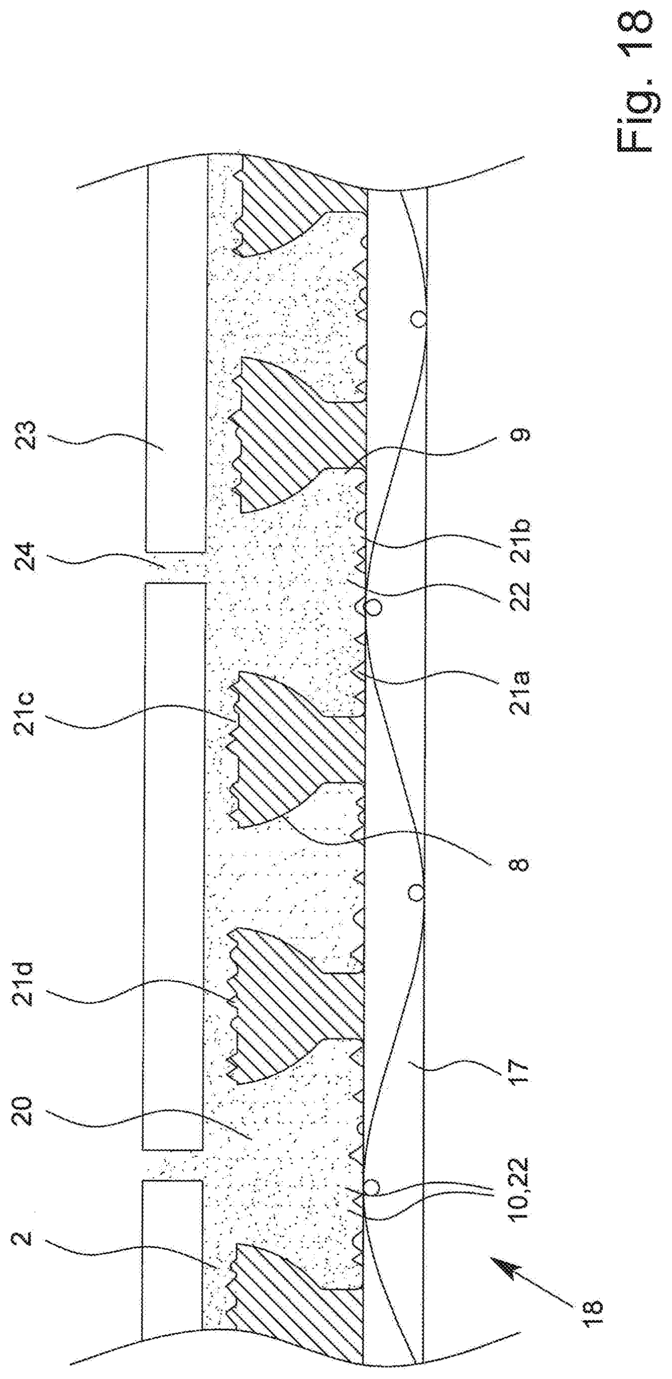
XML
uspto.report is an independent third-party trademark research tool that is not affiliated, endorsed, or sponsored by the United States Patent and Trademark Office (USPTO) or any other governmental organization. The information provided by uspto.report is based on publicly available data at the time of writing and is intended for informational purposes only.
While we strive to provide accurate and up-to-date information, we do not guarantee the accuracy, completeness, reliability, or suitability of the information displayed on this site. The use of this site is at your own risk. Any reliance you place on such information is therefore strictly at your own risk.
All official trademark data, including owner information, should be verified by visiting the official USPTO website at www.uspto.gov. This site is not intended to replace professional legal advice and should not be used as a substitute for consulting with a legal professional who is knowledgeable about trademark law.