Sheet Holding Device, Image Forming Apparatus, And Image Reading Device
Sugita; Junichi
U.S. patent application number 16/677952 was filed with the patent office on 2020-05-14 for sheet holding device, image forming apparatus, and image reading device. This patent application is currently assigned to Ricoh Company, Ltd.. The applicant listed for this patent is Junichi Sugita. Invention is credited to Junichi Sugita.
| Application Number | 20200148492 16/677952 |
| Document ID | / |
| Family ID | 70551800 |
| Filed Date | 2020-05-14 |


View All Diagrams
| United States Patent Application | 20200148492 |
| Kind Code | A1 |
| Sugita; Junichi | May 14, 2020 |
SHEET HOLDING DEVICE, IMAGE FORMING APPARATUS, AND IMAGE READING DEVICE
Abstract
A sheet holding device includes a sheet placement surface and a sheet regulating member. A sheet is to be placed on the sheet placement surface. The sheet regulating member is movable in a contacting direction to contact and a separating direction to separate from an edge of the sheet placed on the sheet placement surface. The sheet regulating member includes a grip portion and a non-grip portion. The grip portion is configured to be gripped by a user to move the sheet regulating member. The non-grip portion is lower in height from the sheet placement surface than the grip portion. The non-grip portion has, on at least one end face in the contacting direction, a slope whose height from the sheet placement surface increases toward a center of the non-grip portion in the contacting direction or the separating direction.
| Inventors: | Sugita; Junichi; (Tokyo, JP) | ||||||||||
| Applicant: |
|
||||||||||
|---|---|---|---|---|---|---|---|---|---|---|---|
| Assignee: | Ricoh Company, Ltd. Tokyo JP |
||||||||||
| Family ID: | 70551800 | ||||||||||
| Appl. No.: | 16/677952 | ||||||||||
| Filed: | November 8, 2019 |
| Current U.S. Class: | 1/1 |
| Current CPC Class: | B65H 5/36 20130101; B65H 1/04 20130101; B65H 2511/20 20130101; B65H 2402/64 20130101; B65H 2701/1315 20130101; B65H 2511/12 20130101; B65H 2407/21 20130101; B65H 3/06 20130101; B65H 2407/20 20130101; B65H 2511/12 20130101; B65H 2220/01 20130101; B65H 2511/20 20130101; B65H 2220/02 20130101 |
| International Class: | B65H 5/36 20060101 B65H005/36; B65H 3/06 20060101 B65H003/06 |
Foreign Application Data
| Date | Code | Application Number |
|---|---|---|
| Nov 13, 2018 | JP | 2018-212701 |
Claims
1. A sheet holding device comprising: a sheet placement surface on which a sheet is to be placed; and a sheet regulating member movable in a contacting direction to contact and a separating direction to separate from an edge of the sheet placed on the sheet placement surface, the sheet regulating member including: a grip portion configured to be gripped by a user to move the sheet regulating member; and a non-grip portion lower in height from the sheet placement surface than the grip portion, the non-grip portion having, on at least one end face in the contacting direction, a slope whose height from the sheet placement surface increases toward a center of the non-grip portion in the contacting direction or the separating direction.
2. The sheet holding device according to claim 1, wherein a whole of the at least one end face of the non-grip portion is the slope.
3. The sheet holding device according to claim 1, wherein the slope is a curved surface whose angle between the sheet placement surface and a tangent line to the slope decreases toward the center of the non-grip portion in the contacting direction or the separating direction.
4. The sheet holding device according to claim 1, wherein the non-grip portion has slopes on both end faces in the contacting direction.
5. The sheet holding device according to claim 4, wherein the contacting direction and the separating direction of the sheet regulating member are orthogonal to a sheet conveyance direction in which the sheet is conveyed from the sheet placement surface, wherein the sheet regulating member includes at least two of non-grip portions, including the non-grip portion, across the grip portion in the sheet conveyance direction, and wherein a non-grip portion of the at least two non-grip portions upstream of the grip portion in the sheet conveyance direction has the slopes on both end faces in the contacting direction.
6. The sheet holding device according to claim 1, wherein the non-grip portion has a sheet regulating surface extending in a normal direction of the sheet placement surface on an end face on a side to contact the edge of the sheet.
7. The sheet holding device according to claim 6, wherein the contacting direction and the separating direction of the sheet regulating member are orthogonal to a sheet conveyance direction in which the sheet is conveyed from the sheet placement surface, wherein the sheet regulating member includes at least two non-grip portions, including the non-grip portion, across the grip portion in the sheet conveyance direction, and wherein a non-grip portion of the at least two non-grip portions downstream of the grip portion in the sheet conveyance direction has the sheet regulating surface.
8. The sheet holding device according to claim 1, further comprising a single guide member extending in the contacting direction and configured to guide and move the sheet regulating member, and wherein the grip portion is disposed at a position overlapping with the single guide member.
9. The sheet holding device according to claim 1, further comprising: two sheet regulating members, including the sheet regulating member, configured to regulate both edges of the sheet placed on the sheet placement surface; and a moving mechanism configured to move, in conjunction with movement of one of the two sheet regulating members, another one of the sheet regulating members.
10. The sheet holding device according to claim 1, wherein at least one end face of the grip portion in the contacting direction has a recessed shape as viewed in a normal direction of the sheet placement surface.
11. The sheet holding device according to claim 1, wherein the sheet holding device is a sheet feeding tray.
12. An image forming apparatus comprising the sheet holding device according to claim 1.
13. An image reading device comprising the sheet holding device according to claim 1.
Description
CROSS-REFERENCE TO RELATED APPLICATION
[0001] This patent application is based on and claims priority pursuant to 35 U.S.C. .sctn. 119(a) to Japanese Patent Application No. 2018-212701, filed on Nov. 13, 2018, in the Japan Patent Office, the entire disclosure of which is incorporated by reference herein.
BACKGROUND
Technical Field
[0002] Aspects of the present disclosure relate to a sheet holding device, an image forming apparatus, and an image reading device.
Discussion of the Background Art
[0003] There has been known a sheet holding device in which a grip portion of a sheet regulating member movable in a contacting/separating direction toward and away from an edge of a sheet placed on a sheet placement surface is gripped by a user so that the sheet regulating member is moved.
[0004] For example, for a manual sheet feeding tray (sheet holding device), a user grips an operation section (grip portion) provided on a side fence (sheet regulating member) and manually moves the side fence.
SUMMARY
[0005] In an aspect of the present disclosure, there is provided a sheet holding device that includes a sheet placement surface and a sheet regulating member. A sheet is to be placed on the sheet placement surface. The sheet regulating member is movable in a contacting direction to contact and a separating direction to separate from an edge of the sheet placed on the sheet placement surface. The sheet regulating member includes a grip portion and a non-grip portion. The grip portion is configured to be gripped by a user to move the sheet regulating member. The non-grip portion is lower in height from the sheet placement surface than the grip portion. The non-grip portion has, on at least one end face in the contacting direction, a slope whose height from the sheet placement surface increases toward a center of the non-grip portion in the contacting direction or the separating direction.
[0006] In another aspect of the present disclosure, there is provided an image forming apparatus that includes the sheet holding device.
[0007] In still another aspect of the present disclosure, there is provided an image reading device that includes the sheet holding device.
BRIEF DESCRIPTION OF THE DRAWINGS
[0008] The aforementioned and other aspects, features, and advantages of the present disclosure would be better understood by reference to the following detailed description when considered in connection with the accompanying drawings, wherein:
[0009] FIG. 1 is a schematic view illustrating a copier according to an embodiment;
[0010] FIG. 2 is an external perspective view illustrating a manual sheet feeder of the copier;
[0011] FIG. 3 is an external perspective view of the copier when a sheet feeding tray is in a closed state in an upright posture;
[0012] FIG. 4 is an external perspective view of the copier when the sheet feeding tray is in an open state in an inclined posture;
[0013] FIG. 5 is a plan view of the sheet feeding tray;
[0014] FIG. 6 is a plan view of the sheet feeding tray on which a sheet is placed;
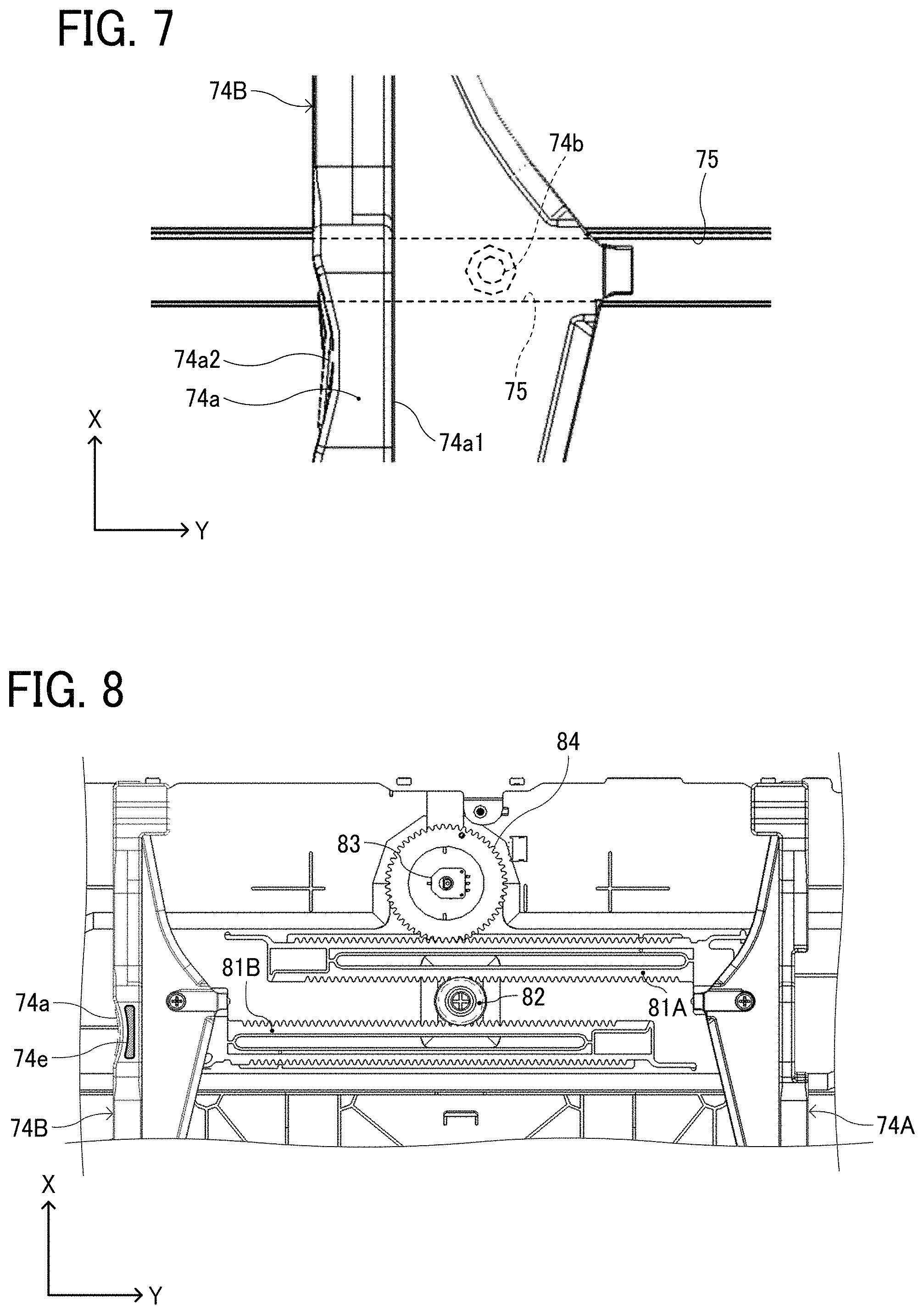
[0015] FIG. 7 is a partially enlarged view illustrating a guide pin of a side fence fitted into a guide rail;
[0016] FIG. 8 is a plan view illustrating a moving mechanism of the side fence in the sheet feeding tray;
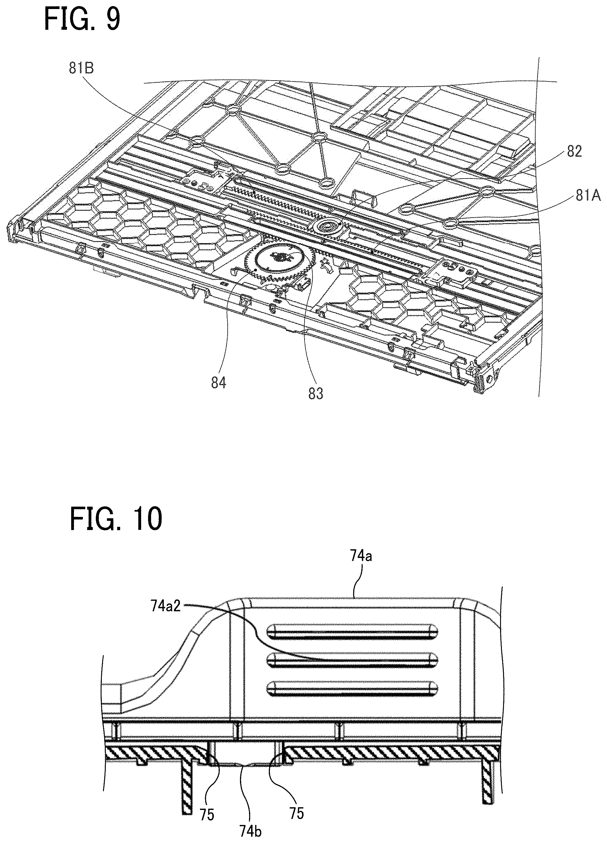
[0017] FIG. 9 is a perspective view illustrating the moving mechanism;
[0018] FIG. 10 is an enlarged view of a grip portion provided on one side fence as viewed from the outside in the sheet width direction;
[0019] FIGS. 11A and 11B are plan views illustrating how a user holds the grip portion with his/her fingers and moves the side fence along the sheet width direction;
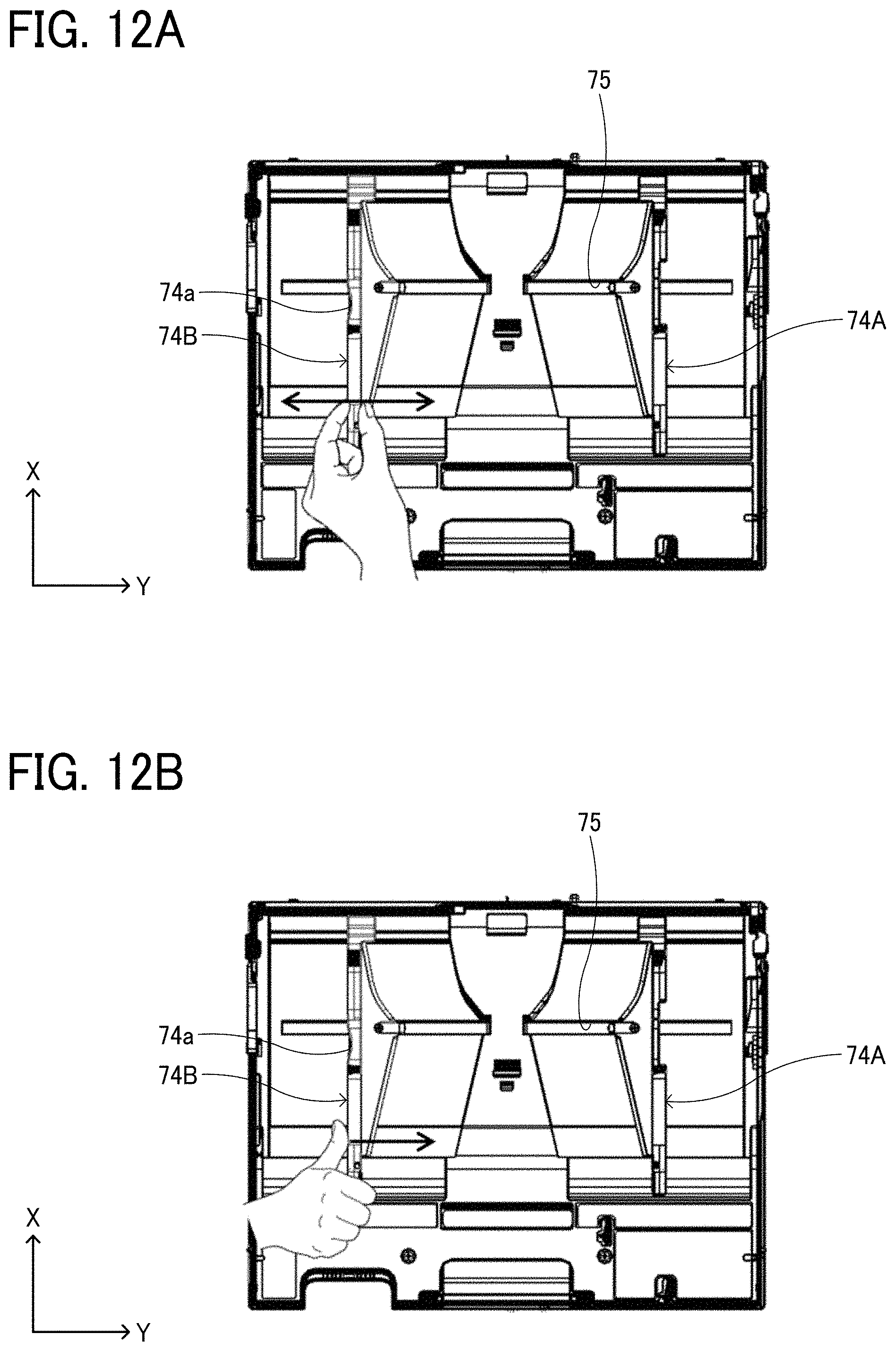
[0020] FIGS. 12A and 12B are plan views illustrating how the user holds a portion other than the grip portion on the side fence with his/her fingers and moves the side fence along the sheet width direction;
[0021] FIG. 13A is a perspective view of the side fence including the grip portion as viewed from the outside in the sheet width direction; FIG. 13B is a perspective view of the side fence as viewed from the inside in the sheet width direction;
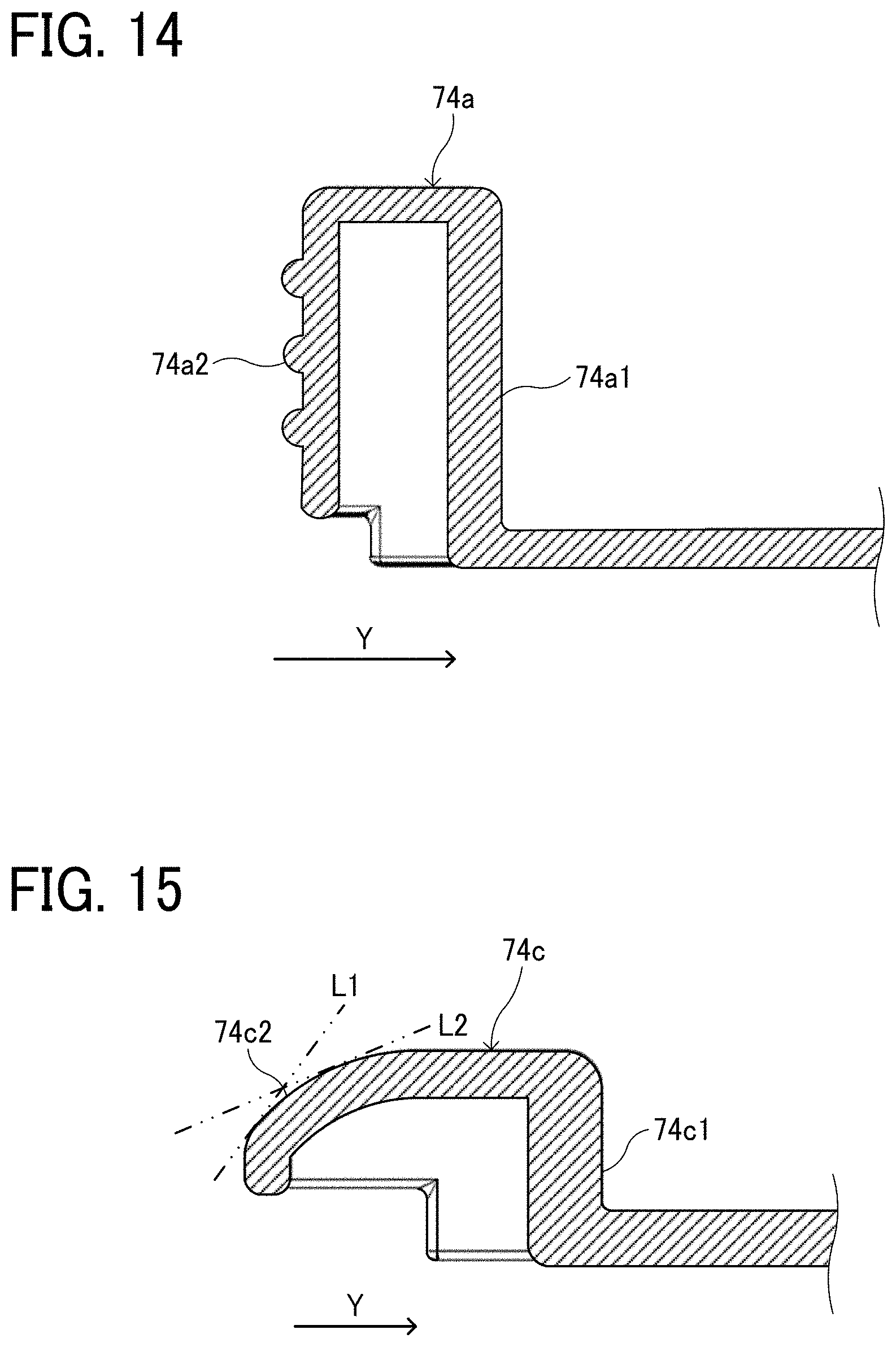
[0022] FIG. 14 is a cross-sectional view of the grip portion cut by a plane orthogonal to the sheet feeding direction;
[0023] FIG. 15 is a cross-sectional view of a non-grip portion adjacent to the downstream side of the grip portion in the sheet feeding direction, which is cut by a plane orthogonal to the sheet feeding direction;
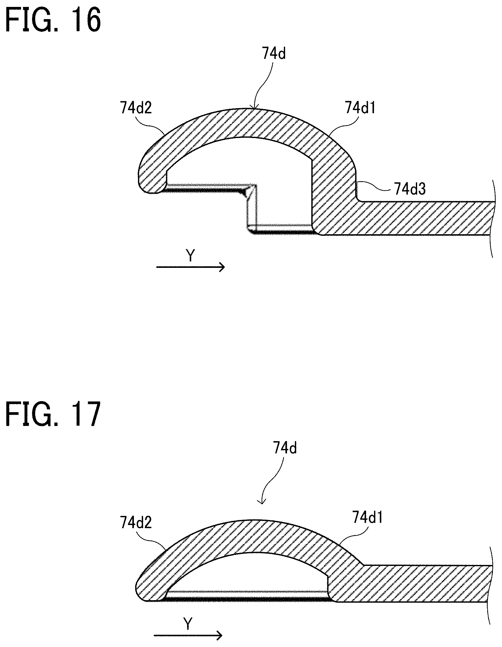
[0024] FIG. 16 is a cross-sectional view of a non-grip portion adjacent to the upstream side of the grip portion in the sheet feeding direction, which is cut by a plane orthogonal to the sheet feeding direction; and
[0025] FIG. 17 is a cross-sectional view illustrating a variation in which the inner end face of the non-grip portion is also formed so that the entire end face is a slope as well as the outer end face.
[0026] The accompanying drawings are intended to depict embodiments of the present disclosure and should not be interpreted to limit the scope thereof. The accompanying drawings are not to be considered as drawn to scale unless explicitly noted.
DETAILED DESCRIPTION
[0027] In describing embodiments illustrated in the drawings, specific terminology is employed for the sake of clarity. However, the disclosure of this patent specification is not intended to be limited to the specific terminology so selected and it is to be understood that each specific element includes all technical equivalents that operate in a similar manner and achieve similar results.
[0028] Although the embodiments are described with technical limitations with reference to the attached drawings, such description is not intended to limit the scope of the disclosure and all of the components or elements described in the embodiments of this disclosure are not necessarily indispensable.
[0029] Referring now to the drawings, embodiments of the present disclosure are described below. In the drawings for explaining the following embodiments, the same reference codes are allocated to elements (members or components) having the same function or shape and redundant descriptions thereof are omitted below.
[0030] Hereinafter, a sheet feeding tray of a copier as an image forming apparatus will be described as a sheet holding device according to an embodiment of the present disclosure.
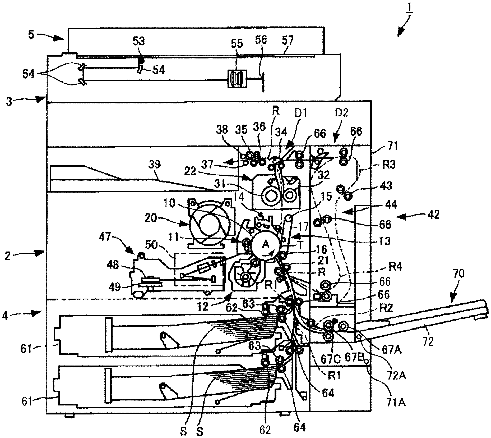
[0031] FIG. 1 is a schematic view illustrating a copier 1 as the image forming apparatus according to the present embodiment.
[0032] The copier 1 according to the present embodiment includes an image forming apparatus main body 2, an image reading device 3 disposed on the image forming apparatus main body 2, a table-shaped sheet feeder 4 disposed below the image forming apparatus main body 2, and an automatic document carrier 5 disposed on the image reading device 3 to be openable and closable. The copier 1 further includes a switchback device 42, and a manual sheet feeder 70.
[0033] The image forming apparatus main body 2 internally includes a drum-shaped photoconductor 10 as an image bearer. A charging device 11 is disposed on the left side in the drawing around the photoconductor 10, and a developing device 12, a transfer device 13, and a cleaning device 14 are disposed along the rotational direction (counterclockwise direction: arrow A in the drawing) of the photoconductor 10. The transfer device 13 includes a transfer belt 17 wound between upper and lower rollers 15 and 16, and the transfer belt 17 is pressed against the circumferential surface of the photoconductor 10 at a transfer position T.
[0034] A toner supply device 20 for supplying new toner to the developing device 12 is disposed on the left side of the charging device 11 and the cleaning device 14. Further, the image forming apparatus main body 2 internally includes a sheet conveyer D1 that feeds a sheet, such as a paper sheet and an overhead projector (OHP) sheet, from a supply position to be described later and conveys the sheet to a stack position through a transfer position T. The sheet conveyer D1 includes a supply path R1, a manual supply path R2, and a sheet conveying path R to be described later. The sheet conveying path R has a substantially L shape extending upward from the bottom of the drawing between the photoconductor 10 and the transfer device 13 and then turning to the left.
[0035] The sheet conveying path R has a registration roller 21 disposed at an upstream position of the photoconductor 10 in the sheet conveyance direction. Further, a fixing device 22 is disposed at a downstream position of the photoconductor 10 in the sheet conveyance direction. The fixing device 22 includes a pair of fixing rollers (fixing rotating bodies) 31 and 32. One of the fixing rollers 31 internally includes a fixing heater, and a pressure spring and a pressure arm are disposed around the other fixing roller 32. The pressure spring and the pressure arm cause one of the fixing rollers 31 to be pressed by the other fixing roller 32. One of the fixing rollers 31 further includes a thermistor and a thermostat.
[0036] The fixing heater turns on or off the fixing heater using the thermostat while measuring a temperature of the fixing roller 31 using the thermistor, thereby keeping one of the fixing rollers 31 at a predetermined temperature.
[0037] At further downstream of the fixing device 22 in the sheet conveyance direction, there are disposed an ejection bifurcating claw 34, an ejection roller 35, a first pressure roller 36, a second pressure roller 37, and a stiffening roller 38, and further ahead of those components, there is disposed an ejection stack section (ejection position) 39 for stacking sheets having been subject to image formation.
[0038] A laser writing device 47 is disposed on the left side of the developing device 12 in the drawing. The laser writing device 47 includes a laser light source, a rotary polygon mirror 48 for scanning, a polygon motor 49, a scanning optical system 50, such as an fO lens, and the like.
[0039] The image reading device 3 includes a light source 53, a plurality of mirrors 54, an imaging optical lens 55, an image sensor 56, such as a charge-coupled device (CCD), and the like, and a contact glass 57 is disposed on the upper surface.
[0040] One end of the automatic document carrier 5 is connected to one end of the upper surface of the image reading device 3 by a connector having a hinge structure. The automatic document carrier 5 is provided in such a manner that the lower surface is openable and closable in a state where the inclination angle with the upper surface of the contact glass 57 is, for example, 90 degrees at the maximum from the horizontal state of pressing a document sheet placed on the upper surface of the contact glass 57 from above. The automatic document carrier 5 includes, in addition to a placing table 5A at the document placing position and an ejection table 5B at the ejecting position, a sheet conveyer including a document conveying path for conveying a sheet, such as a document sheet, from the placing table 5A to the ejection table 5B through the reading position on the contact glass 57 of the image reading device 3. The sheet conveyer includes a plurality of sheet conveying rollers (sheet conveyance rotating body) for conveying a sheet, such as a document sheet.
[0041] The sheet feeder 4 internally includes sheet separating devices 61, which are supply positions of a sheet S, in multiple stages. Each of the sheet separating devices 61 includes a corresponding pickup roller (feeding roller) 62, a feed roller (feeding roller) 63, and a reverse roller (separating roller) 64. The supply path R1 communicating with the sheet conveying path R of the image forming apparatus main body 2 is formed on the right side of the sheet separating devices 61 disposed in multiple stages in the drawing. The supply path R1 includes a number of sheet conveying rollers (sheet conveyance rotating bodies) 66 for conveying a sheet.
[0042] The switchback device 42 is disposed on the right side of the image forming apparatus main body 2 in the drawing. The switchback device 42 includes a sheet conveyer D2 that branches from the position of the ejection bifurcating claw 34 of the sheet conveying path R. The sheet conveyer D2 includes a reverse path R3 leading to a switchback position 44 at which a pair of switchback rollers 43 is disposed, and a re-conveying path R4 leading to, from the switchback position 44, the registration roller 21 of the sheet conveying path R again. The sheet conveyer D2 further includes the plurality of sheet conveying rollers (sheet conveyance rotating bodies) 66 for conveying a sheet. In the present embodiment, the switchback device 42 is attached to an opening and closing member 71 to be described later.
[0043] The manual sheet feeder 70 is disposed on the right side of the image forming apparatus main body 2 in the drawing. The manual sheet feeder 70 includes a pickup roller (feeding roller) 67A, a feed roller (feeding roller) 67B, and a reverse roller (separating roller) 67C, and supplies the sheet S stacked on the sheet feeding tray 72 to the sheet conveying path R of the image forming apparatus main body 2.
[0044] Next, operation of the copier 1 will be described.
[0045] First, to generate a copy using the copier 1, a main switch is turned on and a document is set in the automatic document carrier 5. Alternatively, the automatic document carrier 5 is opened, a document is directly set on the contact glass 57 of the image reading device 3, and then the automatic document carrier 5 is closed to press the document.
[0046] Then, when a start switch is pressed, in the case where the document is set in the automatic document carrier 5, the document is moved through the document conveying path onto the contact glass 57 by the sheet conveying roller, the image reading device 3 is driven, the content of the document is read, and then the document is ejected onto the ejection table. On the other hand, in the case where the document is directly set on the contact glass 57, the image reading device 3 is driven immediately.
[0047] When the image reading device 3 starts driving, the light source 53 moves along the contact glass 57 while emitting light, and irradiates the document surface on the contact glass 57 with light. The plurality of mirrors 54 receives light reflected from the document surface, and reflects the light toward the imaging optical lens 55. The imaging optical lens 55 forms an image of the reflected light on the image sensor 56. The image sensor 56 reads the content of the document, accordingly.
[0048] At the same time, the photoconductor 10 is rotated by a photoconductor drive motor, and along with this, the surface of the photoconductor is uniformly charged by the charging device 11 using a charging roller, and then the laser writing device 47 irradiates the surface of the photoconductor with laser light according to the content of the document read by the image reading device 3 described above so that writing is performed on the surface of the photoconductor, thereby forming an electrostatic latent image on the surface of the photoconductor 10. Subsequently, toner is attracted to the surface of the photoconductor when the portion of the electrostatic latent image formed on the surface of the photoconductor faces the developing device 12, whereby the electrostatic latent image is made into a visible image.
[0049] Further, when the start switch is pressed, among the plurality of sheet separating devices 61 provided in multiple stages in the sheet feeder 4, a corresponding sheet separating device 61 is selected on the basis of sheet size selecting signals. Then, a pickup roller 62 corresponding to the sheet separating device 61 feeds one sheet S in the sheet separating device 61. The reverse roller 64 separates the uppermost sheet S when attempting to feed a plurality of sheets S, and blocks the conveyance of the remaining sheets S. Subsequently, the feed roller 63 inserts the sheet S into the supply path R1 while conveying the sheet S, the sheet conveying roller 66 successively conveys the sheet S and guides it to the sheet conveying path R, and the registration roller 21 abuts on the sheet S to stop the conveyance of the sheet S. Then, the registration roller 21 rotates in synchronization with the rotation of the photoconductor 10 described above, and feeds the sheet S to the right side of the photoconductor 10.
[0050] In the case of performing the manual sheet feeding, the sheet feeding tray 72 of the manual sheet feeder 70 is sifted from the closed state in the upright posture to the open state in the inclined posture as illustrated in FIG. 1, and a sheet is set on a sheet placement surface 72B of the sheet feeding tray 72. When the start switch is pressed, the pickup roller 67A feeds one sheet, and then the feed roller 67B successively feeds the sheet. The reverse roller 67C separates the uppermost sheet when attempting to feed a plurality of sheets, and blocks the conveyance of the remaining sheets. The sheet conveying roller 66 continues to convey the sheet supplied to the manual supply path R2, and guides it to the sheet conveying path R. Thereafter, in a similar manner to the sheet feeder 4 described above, the registration roller 21 feeds the sheet to the right side of the photoconductor 10 in synchronization with the rotation of the photoconductor 10.
[0051] Subsequently, the transfer device 13 transfers the toner image on the photoconductor 10 onto the sheet S to form an image when the sheet S fed to the right side of the photoconductor 10 comes to the transfer position T. The cleaning device 14 removes and cleans the residual toner on the photoconductor 10 after the image transfer, and then a static eliminator removes the residual potential on the photoconductor 10 to prepare for the next image formation starting from the charging device 11.
[0052] Next, the fixing device 22 conveys the sheet S bearing the above-described transferred toner image with the transfer belt 17 through the space between the pair of fixing rollers 31 and 32, and applies heat and pressure at the fixing position to fix the transferred image. The sheet S having been subject to the fixing is made into a flat surface and is stiffened in the process of passing through the first pressure roller 36, the ejection roller 35, the second pressure roller 37, and the stiffening roller 38, ejected onto the ejection stack section 39, and is stacked.
[0053] Note that the ejection bifurcating claw 34 is switched in the case of transferring the image onto both sides of the sheet S. Then, the sheet S bearing the image transferred to its surface is inserted from the sheet conveying path R to the reverse path R3, conveyed by the sheet conveying roller 66 to be inserted to the switchback position 44, and then switchback is carried out at the switchback position 44. Thereafter, the sheet is put into the re-conveying path R4 and is reversed, conveyed by the sheet conveying roller 66, guided to the sheet conveying path R again, and an image is transferred onto the back side of the sheet as well in a similar manner to the descriptions above.
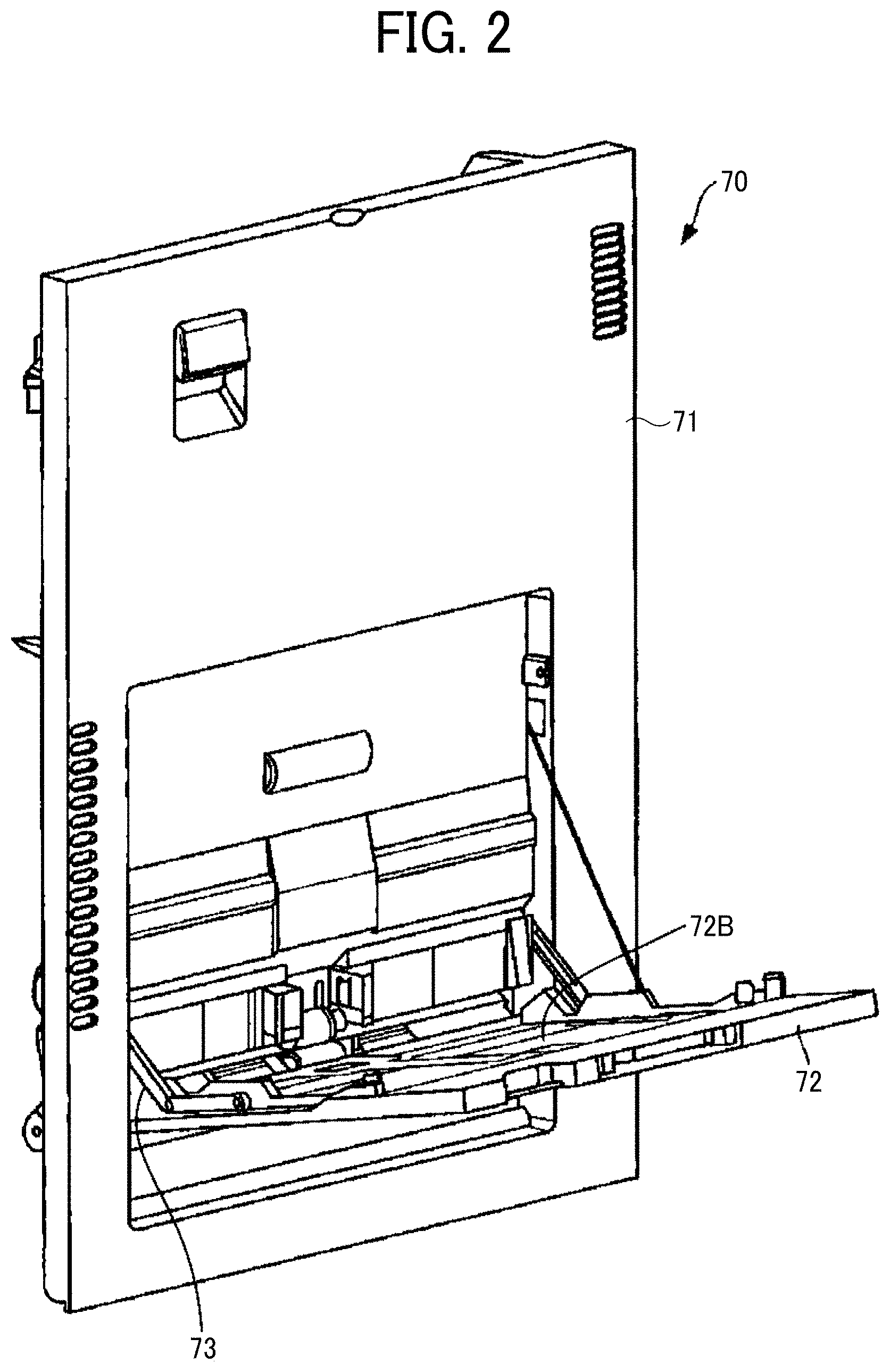
[0054] FIG. 2 is an external perspective view illustrating the manual sheet feeder 70.
[0055] As illustrated in FIG. 1, the manual sheet feeder 70 according to the present embodiment includes the opening and closing member 71 whose upper portion is opened and closed with a pivot fulcrum 71A being held at a lower part with respect to the image forming apparatus main body 2, and the sheet feeding tray 72 whose upper portion is opened and closed with a pivot fulcrum 72A being held at a lower part with respect to the opening and closing member 71. As illustrated in FIG. 2, the manual sheet feeder 70 further includes a link member 73 that connects the opening and closing member 71 to the image forming apparatus main body 2 in an openable/closable manner.
[0056] In order to easily remove paper jam sheets clogged in the sheet conveying path R or the re-conveying path R4, perform maintenance on the inside of the image forming apparatus main body 2, and the like, the opening and closing member 71 is made into the open state in the inclined posture, and the sheet conveying path R or the re-conveying path R4 is opened. That is, the manual sheet feeder 70 shifts the opening and closing member 71 from the closed state in the upright posture to the open state in the inclined posture, and opens the sheet conveying path R or the re-conveying path R4, whereby the removal of the paper jam sheets, the maintenance, and the like can be easily performed.
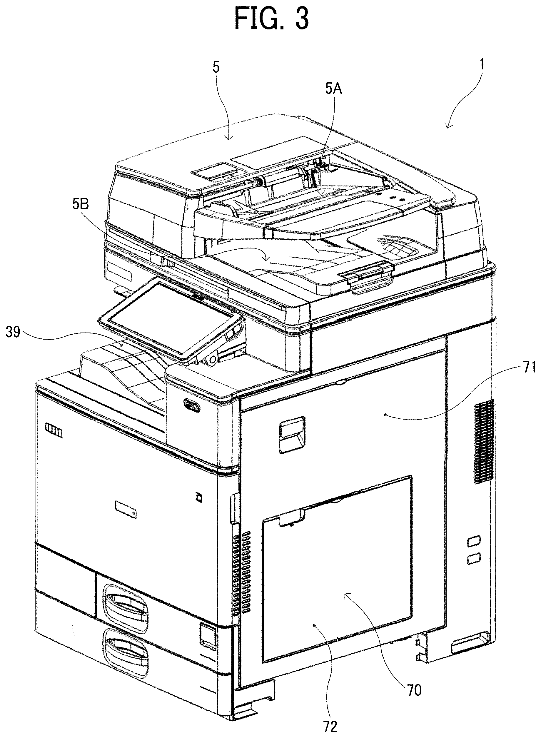
[0057] Furthermore, the manual sheet feeder 70 shifts the sheet feeding tray 72 from the closed state in the upright posture as illustrated in FIG. 3 to the open state in the inclined posture as illustrated in FIG. 4, and stacks sheets on the sheet placement surface 72B of the sheet feeding tray 72, whereby sheets for manual feeding can be supplied to the sheet conveying path R.
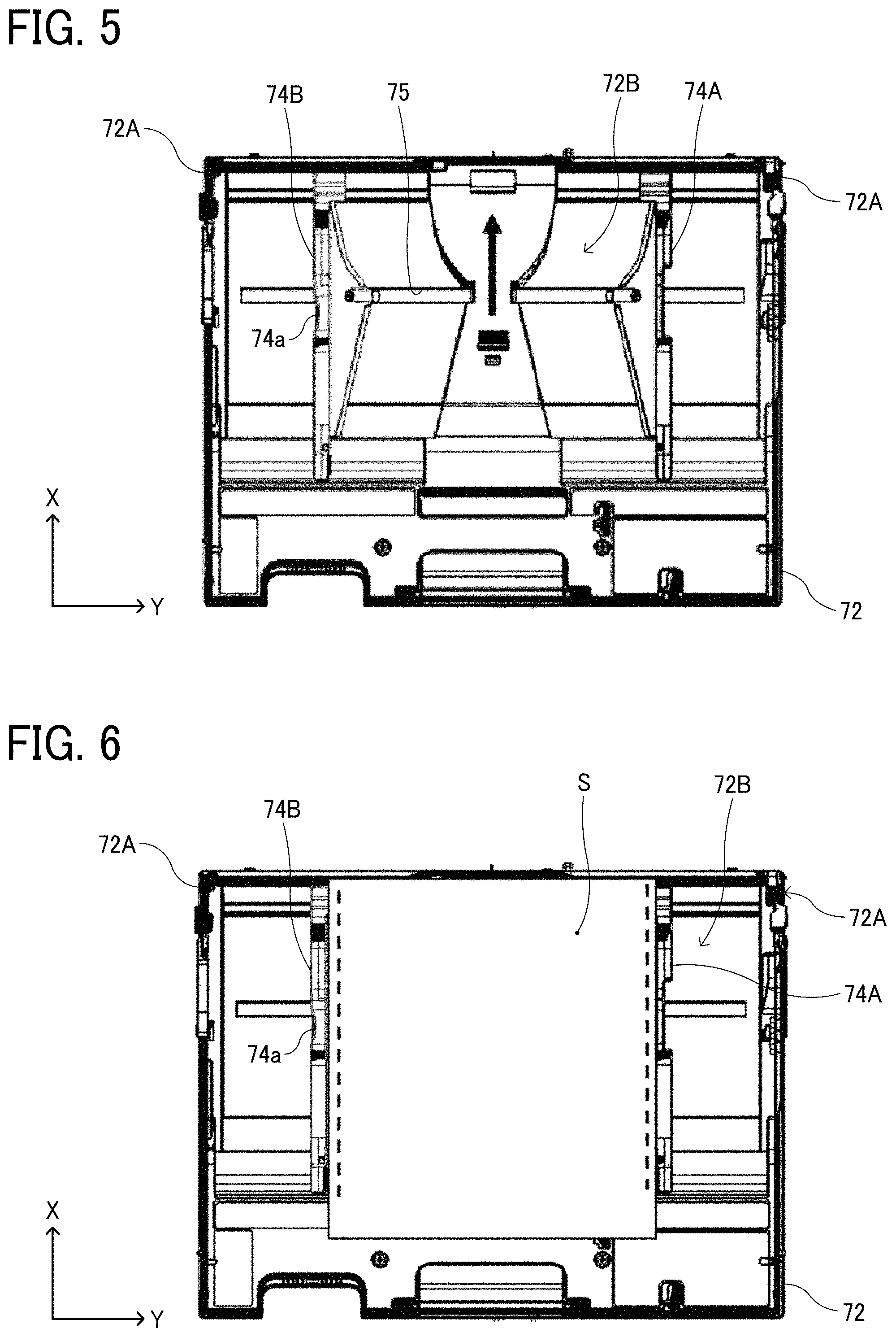
[0058] FIG. 5 is a plan view of the sheet feeding tray 72 according to the present embodiment.
[0059] FIG. 6 is a plan view of the sheet feeding tray 72 on which the sheet S is placed.
[0060] The sheet feeding tray 72, which is a sheet holding device, includes side fences 74A and 74B, and a guide rail 75. Two side fences 74A and 74B are installed in the sheet width direction (Y direction) in the space above the sheet placement surface 72B (loading space of the sheet S).
[0061] The sheet feeding tray 72 according to the present embodiment includes the guide rail 75 as a guide member extending in the sheet width direction (Y direction). As illustrated in FIG. 7, the pair of side fences 74A and 74B installed at both ends in the sheet width direction to sandwich the sheet S includes a guide pin 74b to be fitted in the guide rail 75. With the guide pin 74b being guided to the guide rail 75, the side fences 74A and 74B can be manually moved in the contacting/separating direction (sheet width direction) contacting or separated from the edge of the sheet S in the width direction along the guide rail 75, and are positioned corresponding to the size of the sheet S in the width direction. That is, the side fences 74A and 74B function as a sheet regulating member that regulates the position of the sheet S in the width direction.
[0062] In the sheet feeding tray according to the present embodiment, there may be provided an end fence on the upstream side in the sheet feeding direction (X direction) in the space above the sheet placement surface 72B (loading space of the sheet S). Specifically, the sheet feeding tray 72 includes a guide rail as a guide member extending in the sheet feeding direction (X direction), and an end fence is installed along the guide rail to be movable in the sheet feeding direction, for example. The end fence is positioned corresponding to the size of the sheet S placed on the sheet placement surface 72B in the feeding direction. That is, the end fence functions as a sheet regulating member that regulates the position of the edge of sheet S in the feeding direction.
[0063] In the present embodiment, the pair of side fences 74A and 74B interlocks to increase or decrease the interval in the width direction. That is, when one of the side fences 74A and 74B is manually moved in the +Y direction, in conjunction with that, the other one of the side fences 74B and 74A moves in the -Y direction. When one of the side fences 74A and 74B is manually moved in the -Y direction, in conjunction with that, the other one of the side fences 74B and 74A moves in the +Y direction.
[0064] Note that, although the feeding direction (sheet conveyance direction) of the sheet S is X direction and the sheet feeding tray 72 can be inserted/removed in the Y direction in FIGS. 5 and 6, embodiments of the present disclosure are not limited to those directional relationships.
[0065] FIG. 8 is a plan view illustrating a moving mechanism of the side fences 74A and 74B in the sheet feeding tray 72 according to the present embodiment. FIG. 9 is a perspective view illustrating the moving mechanism of the side fences 74A and 74B in the sheet feeding tray 72 according to the present embodiment. Note that FIG. 9 illustrates a state in which the side fences 74A and 74B are removed.
[0066] In the moving mechanism of the side fences 74A and 74B according to the present embodiment, the pair of side fences 74A and 74B moves in conjunction with each other so that the center of the sheet S in the width direction matches the center of the sheet placement surface 72B in the width direction even if the size of the sheet S in the width direction changes. In the present embodiment, a pinion rack mechanism is used as the moving mechanism of the side fences 74A and 74B.
[0067] Specifically, as illustrated in FIG. 8, each of the side fences 74A and 74B includes racks 81A and 81B. Each of the racks 81A and 81B is engaged with the pinion to sandwich the pinion 82 disposed at the approximate center in the sheet width direction from both sides. Accordingly, when one of the side fences 74A and 74B moves in the sheet width direction, the racks 81A and 81B of the side fences 74A and 74B interlock to move in the sheet width direction, thereby rotating the pinion 82. The rotation of the pinion 82 causes the other racks 81B and 81A to move in the passing direction along the sheet width direction, and in conjunction with that, the other one of the side fences 74B and 74A moves in the sheet width direction.
[0068] In the present embodiment, one of the racks 81A is engaged with a gear (rotating member) 84. The gear 84 has a rotation shaft 84a, which is fitted into an engagement hole 83b on a rotor (detected member) 83a of a rotary sensor 83 and connected. For example, when a user moves the side fence 74A in the sheet width direction, the rack 81A of the side fence 74A interlocks to move in the sheet width direction, thereby rotating the gear 84 engaged with the rack 81A. As a result, the rotor 83a of the rotary sensor 83 connected to the gear 84 rotates integrally with the gear 84, and the rotation amount of the rotor 83a is detected by the rotary sensor 83. The detection result (rotation amount of the rotor 83a) of the rotary sensor 83 is transmitted to a control unit of the image forming apparatus, and is used to determine, for example, the size of the sheet S set on the sheet feeding tray 72 in the width direction.
[0069] FIG. 10 is an enlarged view of the grip portion 74a provided on one of the side fences 74B as viewed from the outside in the sheet width direction.
[0070] The sheet feeding tray 72 according to the present embodiment is configured such that the user grips the grip portion 74a provided on one of the side fences 74B and moves the side fences 74A and 74B along a sheet width direction Y. Specifically, as illustrated in FIG. 11A, the user grips the grip portion 74a provided on one of the side fences 74B with his/her fingers in the sheet width direction Y, and moves the side fences 74A and 74B along the sheet width direction Y, for example. Alternatively, as illustrated in FIG. 11B, the user may push the outer surface of the grip portion 74a in the sheet width direction with his/her finger, thereby moving the side fences 74A and 74B in the sheet width direction Y, for example.
[0071] The sheet feeding tray 72 according to the present embodiment has a configuration in which the side fences 74A and 74B are guided by a single guide rail 75, and as illustrated in FIG. 10 and the like, the grip portion 74a is disposed at a position overlapping the guide rail 75. Accordingly, when the user grips the grip portion 74a and moves one of the side fences 74B in the sheet width direction Y, a rotational moment centered on a guide pin 74b of one of the side fences 74B does not occur, or its magnitude is small even if the rotational moment occurs. Therefore, the contact pressure between the guide pin 74b provided on one of the side fences 74B and the guide rail 75 is relatively small, and the frictional force at the time of sliding of both components is small. In addition, the rack 81B provided on one of the side fences 74B moves approximately straight along its longitudinal direction, a proper engagement state between the rack 81B and the pinion 82 is maintained, the pinion 82 can rotate smoothly, and the moving load received from the pinion 82 is also small. Therefore, one of the side fences 74B and the other one of the side fences 74A moving in conjunction with the side fence 74B can move smoothly.
[0072] However, there may be a case where, as illustrated in FIG. 12A, the user grips a portion other than the grip portion 74a on one of the side fences 74B, or as illustrated in FIG. 12B, the user pushes a portion other than the grip portion 74a with his/her finger to attempt to move the side fence 74B. In that case, the portion gripped or pushed by the user with his/her fingers is largely shifted in the sheet feeding direction from the guide pin 74b of one of the side fences 74B fitted into the guide rail 75, whereby a large rotational moment centered on the guide pin 74b occurs. Therefore, force to rotate around the guide pin 74b acts on one of the side fences 74B, and the rack 81B of one of the side fences 74B is pressed against the pinion 82 accordingly, whereby the contact pressure between the guide pin 74b of one of the side fences 74B and the guide rail 75 increases by receiving the reaction force. As a result, the frictional force between the guide pin 74b and the guide rail 75 increases, and one of the side fences 74B and the other one of the side fences 74A that moves in conjunction with the side fence 74B cannot move smoothly.
[0073] Also in a case where the user grips or pushes a portion where a rotational moment in the reverse direction occurs with his/her fingers, the frictional force between the guide pin 74b and the guide rail 75 increases similarly, whereby one of the side fences 74B and the other one of the side fences 74A that moves in conjunction with the side fence 74B cannot move smoothly. In addition, one of the side fences 74B tends to rotate in the direction in which the rack 81B is away from the pinion 82 so that the engagement between the rack 81B and the pinion 82 may be disengaged, and in such a case, the sheet S cannot match the center of the sheet placement surface 72B in the width direction. Furthermore, the size of the sheet S set on the sheet feeding tray 72 in the width direction cannot be properly determined from the detection result of the rotary sensor 83.
[0074] In view of the above, in the present embodiment, the configuration of the side fence 74B is devised in such a manner that the user does not grips a portion other than the grip portion 74a of the side fence 74B to move the side fence 74B.
[0075] FIG. 13A is a perspective view of the side fence 74B including the grip portion 74a as viewed from the outside in the sheet width direction.
[0076] FIG. 13B is a perspective view of the side fence 74B including the grip portion 74a as viewed from the inside in the sheet width direction.
[0077] FIG. 14 is a cross-sectional view of the grip portion 74a cut by a plane orthogonal to the sheet feeding direction.
[0078] The side fence 74B according to the present embodiment includes the grip portion 74a near the center of a sheet feeding direction X. As illustrated in FIG. 14, in the grip portion 74a, an end face 74al (hereinafter referred to as an "inner end face") on the side in contact with the edge of the sheet S is a sheet regulating surface extending in the normal direction of the sheet placement surface 72B, and the edge of the sheet stacked on the sheet placement surface 72B abuts on the inner end face 74al of the grip portion 74a, thereby regulating the position of a bundle of the sheets S in the width direction.
[0079] On the other hand, an end face 74a2 (hereinafter referred to as an "outer end face") opposite to the inner end face 74al of the grip portion 74a is an uneven surface in which unevenness is continuous in the vertical direction so that the user's finger does not slip in the vertical direction. As illustrated in FIGS. 7, 13A, and 13B, the outer end face 74a2 of the grip portion 74a is in a recessed shape as viewed in the normal direction of the sheet placement surface 72B. This makes it difficult for the user's finger to slip in the horizontal direction as well. Moreover, with such an uneven surface and a recessed shape, the user can easily recognize that the grip portion 74a is a portion to be gripped, and it is suppressed that the user grips a portion other than the grip portion 74a of the side fence 74B and moves the side fence 74B. In particular, as illustrated in FIG. 8, a mark 74e is silk-printed on the upper surface of the grip portion 74a to highlight the position of the grip portion, which serves as assistance for the user to easily recognize the position of the grip portion 74a when the user looks at the side fence 74B from above.
[0080] The grip portion 74a is formed to be higher in height from the sheet placement surface 72B than non-grip portions 74c and 74d adjacent to the upstream side and the downstream side in the sheet feeding direction. Therefore, the grip portion 74a is easier to grip with the user's finger than the non-grip portions 74c and 74d. Conversely, since the non-grip portions 74c and 74d are lower in height from the sheet placement surface 72B than the grip portion 74a, it is more difficult for the user to grip than the grip portion 74a. Therefore, it is suppressed that the user grips the non-grip portions 74c and 74d, which are other than the grip portion 74a of the side fence 74B, and moves the side fence 74B.
[0081] Moreover, in the non-grip portions 74c and 74d according to the present embodiment, at least one end face in the sheet width direction Y has a slope where a height from the sheet placement surface 72B increases as it goes inward from the outside in the sheet width direction Y. Specifically, as illustrated in FIG. 15, the non-grip portion 74c adjacent to the downstream side of the grip portion 74a in the sheet feeding direction has a slope 74c2 on the end face outside in the sheet width direction, and as illustrated in FIG. 16, the non-grip portion 74d adjacent to the upstream side of the grip portion 74a in the sheet feeding direction has slopes 74d1 and 74d2 on both end faces in the sheet width direction Y. As a result, the user's finger is less likely to be caught on the end face than in the case where the slope is a plane orthogonal to the sheet placement surface 72B.
[0082] In a case where the slopes 74c2, 74d1, and 74d2 are planes orthogonal to the sheet placement surface 72B like an inner end face (sheet regulating surface) 74c1 of the non-grip portion 74c in the sheet width direction as illustrated in FIG. 15, the user can push the planes straight in the normal direction with his/her finger to move the side fence 74B. Accordingly, a situation in which the user's finger slips on the planes is unlikely to occur, whereby the user can easily grip the non-grip portions 74c and 74d and move the side fence 74B.
[0083] Meanwhile, in the case of the slopes 74c2, 74d1, and 74d2 as in the present embodiment, the direction pushed by the user's finger (direction parallel to the sheet width direction) is inclined relative to the normal direction of the slopes 74c2, 74d1, and 74d2. In that case, force is generated in the direction in which the user's finger slides on the slope, whereby the user's finger is likely to slip on the slope. Accordingly, even if the user attempts to grip the non-grip portions 74c and 74d, which are portions other than the grip portion 74a of the side fence 74B, to move the side fence 74B, the finger slips and cannot successfully move the side fence 74B. As a result, it is suppressed that the user grips the non-grip portions 74c and 74d and moves the side fence 74B.
[0084] In particular, the entire outer end faces of the non-grip portions 74c and 74d according to the present embodiment are the slopes 74c2 and 74d2, whereby there is substantially no portion at which the user's finger can push the end face straight in the normal direction. Therefore, it is more reliably suppressed that the user grips the non-grip portions 74c and 74d and moves the side fence 74B.
[0085] As illustrated in FIG. 15, the slope 74c2 according to the present embodiment is a curved surface in which the angle between tangent lines L1 and L2 and the sheet placement surface 72B decreases as it goes inward from the outside in the sheet width direction Y. With such a curved surface, the contact area with the user's finger is made small, and the finger is further slippery, whereby it is suppressed that the user grips the non-grip portion 74c and moves the side fence 74B. The same applies to the slopes 74d1 and 74d2 of the non-grip portion 74d.
[0086] Meanwhile, as illustrated in FIGS. 15 and 16, the inner end faces of the non-grip portions 74c and 74d according to the present embodiment have sheet regulating surfaces 74c1 and 74d3 extending in the normal direction of the sheet placement surface 72B. Accordingly, the edge of the sheet S placed on the sheet placement surface 72B abuts on the sheet regulating surfaces 74c1 and 74d3 on the inner end faces of the non-grip portions 74c and 74d, whereby the position of the bundle of the sheets S in the width direction can be regulated.
[0087] In particular, in the present embodiment, the entire inner end face of the non-grip portion 74c adjacent to the grip portion 74a on the downstream side in the sheet feeding direction is the sheet regulating surface 74c1, and the inner end face has no slope, as illustrated in FIG. 15. In that case, when the user grips the non-grip portion 74c, the user can push the sheet regulating surface 74c1 straight in the normal direction with his/her finger, whereby the effect of suppressing the situation in which the user grips the non-grip portion 74c and moves the side fence 74B is reduced.
[0088] However, for the user, it is generally easier to operate at a position far from the outer wall surface of the image forming apparatus main body 2 with respect to the side fence 74B on the sheet feeding tray 72 protruding from the outer wall surface of the image forming apparatus main body 2. In view of the above, the non-grip portion 74c adjacent to the grip portion 74a on the downstream side in the sheet feeding direction is at a position near the image forming apparatus main body 2 on the sheet feeding tray 72, which is at a position difficult to be operated by the user within the side fence 74B. Therefore, it can be said that, even if the suppression effect is reduced, the non-grip portion 74c has less influence on the overall suppression effect.
[0089] Meanwhile, when the position of the sheet S placed on the sheet placement surface 72B of the sheet feeding tray 72 in the width direction is regulated, from the viewpoint of preventing skew of the sheet S, for example, positional regulation of the sheet S on the downstream side in the feeding direction is of higher level of importance than positional regulation on the upstream side. Therefore, in the present embodiment, the non-grip portion 74c adjacent to the grip portion 74a on the downstream side in the sheet feeding direction prioritizes the positional regulation even if the suppression effect is reduced, and the entire inner end face of the non-grip portion 74c serves as the sheet regulating surface 74c1 and has no slope.
[0090] In addition, the non-grip portion 74d adjacent to the grip portion 74a on the upstream side in the sheet feeding direction is at a position far from the image forming apparatus main body 2 on the sheet feeding tray 72, which is at a position easily operated by the user. Therefore, the entire inner end face of the non-grip portion 74d does not serve as the sheet regulating surface 74d3 so that the suppression effect is not reduced, and has the slope 74d1. In that case as well, in consideration of the effect of suppressing the situation in which the user grips the non-grip portion 74d and moves the side fence 74B, half or more of the inner end face of the non-grip portion 74d in the height direction is preferably the slope 74d1. Note that, as illustrated in FIG. 17, the inner end face of the non-grip portion 74d may be formed so that the entire end face is a slope in the same manner as the outer end face.
[0091] Note that, although the sheet feeding tray 72 has been described in the present embodiment, the sheet holding device according to an embodiment of the present disclosure is not limited to the sheet feeding tray 72 but may be, for example, a sheet container in the sheet separating device 61 of the sheet feeder 4, a placing table of the automatic document carrier 5 in the image reading device, or the like as long as sheets are held.
[0092] The descriptions above represent merely an example, and specific effects can be exerted in the following aspects.
[0093] First Aspect According to a first aspect, there is provided a sheet holding device (e.g., sheet feeding tray 72) in which the user grips a grip portion (e.g., grip portion 74a) of a sheet regulating member (e.g., side fences 74A and 74B) movable in a contacting direction (e.g., sheet width direction Y) to contact and a separating direction to separate from an edge of a sheet (e.g., sheet S) placed on a sheet placement surface (e.g., sheet placement surface 72B) and moves the sheet regulating member, in which a non-grip portion (e.g., non-grip portions 74c and 74d) of the sheet regulating member lower in height from the sheet placement surface than the grip portion has, on at least one end face in the contacting direction, a slope (e.g., slopes 74c2, 74d1, and 74d2) whose height from the sheet placement surface increases toward a center of the non-grip portion in the contacting direction or the separating direction.
[0094] In the present aspect, since the non-grip portion of the sheet regulating member is lower in height from the sheet placement surface than the grip portion, it is more difficult for the user to grip than the grip portion. Accordingly, the situation in which the user grips the non-grip portion, which is a portion other than the grip portion of the sheet regulating member, and moves the sheet regulating member is suppressed.
[0095] Furthermore, the non-grip portion has, on at least one end face in the contacting/separating direction, a slope in which the height from the sheet placement surface increases as it goes inward from the outside in the contacting/separating direction, whereby the user's finger is less likely to be caught than in the case where the end face is a plane orthogonal to the sheet placement surface.
[0096] If the slope is a plane orthogonal to the sheet placement surface, the user can push the plane straight in the normal direction with his/her finger and move the sheet regulating member. Accordingly, a situation in which the user's finger slips on the plane is unlikely to occur, whereby the user can easily grip the non-grip portion and move the sheet regulating member. Meanwhile, in the case where at least one end face in the contacting/separating direction is a slope as in the present aspect, the direction pushed by the user's finger (direction parallel to the contacting/separating direction) is inclined relative to the normal direction of the slope. In that case, force is generated in the direction in which the user's finger slides on the slope, whereby the user's finger is likely to slip on the slope. Accordingly, even if the user attempts to grip the non-grip portion, which is a portion other than the grip portion of the sheet regulating member, to move the sheet regulating member, the finger slips and cannot successfully move the sheet regulating member. As a result, the situation in which the user grips the non-grip portion and moves the sheet regulating member is suppressed.
[0097] Second Aspect
[0098] According to a second aspect, the whole of the at least one end face is the slope in the first aspect.
[0099] According to the present aspect, there is substantially no portion at which the user's finger can push the end face of the non-grip portion straight in the normal direction, whereby the situation in which the user grips the non-grip portion and moves the sheet regulating member can be more reliably suppressed.
[0100] Third Aspect
[0101] According to a third aspect, the slope is a curved surface in which the angle between the tangent line and the sheet placement surface decreases inward in the contacting/separating direction in the first or second aspect.
[0102] According to the present aspect, the contact area between the end face of the non-grip portion and the user's finger is smaller than in the case of a flat surface so that the finger is further slippery, whereby the situation in which the user grips the non-grip portion and moves the sheet regulating member is suppressed.
[0103] Fourth Aspect
[0104] According to a fourth aspect, the non-grip portion has slopes on both end faces in the contacting/separating direction in any one of the first to third aspects.
[0105] According to the present aspect, any finger of the user gripping the non-grip portion from both sides is slippery, whereby the situation in which the user grips the non-grip portion and moves the sheet regulating member is suppressed.
[0106] Fifth Aspect
[0107] According to a fifth aspect, in the fourth aspect, the contacting/separating direction of the sheet regulating member is a direction (e.g., sheet width direction Y) orthogonal to the sheet conveyance direction (e.g., sheet feeding direction X), at least two of the non-grip portions exist to sandwich the grip portion in the sheet conveyance direction, and the non-grip portion 74d positioned on the upstream side of the grip portion in the sheet conveyance direction has the slopes 74d1 and 74d2 on both of the end faces.
[0108] In general, the non-grip portion adjacent to the grip portion on the upstream side in the sheet conveyance direction is easier for the user to operate than the non-grip portion adjacent to the grip portion on the downstream side in the sheet conveyance direction. According to the present aspect, the non-grip portion has slopes on both of the end faces so that the non-grip portion, which tends to be operated by the user, is less likely to be gripped, whereby the situation in which the user grips the non-grip portion and moves the sheet regulating member can be effectively suppressed.
[0109] Sixth Aspect
[0110] According to a sixth aspect, in any one of the first to fifth aspects, the non-grip portion has the sheet regulating surfaces 74c1 and 74d3 extending in the normal direction of the sheet placement surface on the end face on the side in contact with the edge of the sheet.
[0111] With this arrangement, positional regulation of the sheet edge is made possible even at the portion of the non-grip portion on the sheet regulating member.
[0112] Seventh Aspect
[0113] According to a seventh aspect, in the sixth aspect, the contacting/separating direction of the sheet regulating member is the direction orthogonal to the sheet conveyance direction, at least two of non-grip portions exist to sandwich the grip portion in the sheet conveyance direction, and the non-grip portion 74c positioned on the downstream side of the grip portion in the sheet conveyance direction has the sheet regulating surface 74c1.
[0114] As described above, when the position of the sheet placed on the sheet placement surface in the width direction is regulated, from the viewpoint of preventing skew of the sheet, for example, positional regulation on the downstream side in the sheet conveyance direction is of higher level of importance than positional regulation on the upstream side. According to the present aspect, it is possible to perform the positional regulation in the sheet width direction with the non-grip portion adjacent to the grip portion on the downstream side in the sheet feeding direction.
[0115] Eighth Aspect
[0116] According to an eight aspect, in any one of the first to seventh aspects, the sheet regulating member moves while being guided by a single guide member (e.g., guide rail 75) extending in the contacting/separating direction, and the grip portion is disposed at a position overlapping the single guide member.
[0117] According to the present aspect, as described above, when the user grips the grip portion and moves the sheet regulating member in the contacting/separating direction, no rotational moment is generated centered on the portion (guide pin 74b) on the sheet regulating member guided by the single guide member, or its magnitude is small even if the rotational moment is generated. Accordingly, the contact pressure between the sheet regulating member and the guide member is relatively small, and frictional force at the time of sliding between the two components can be made small. Therefore, when the user grips the grip portion and moves the sheet regulating member, the sheet regulating member can be moved smoothly.
[0118] Ninth Aspect
[0119] According to a ninth aspect, in any one of the first to eight aspects, two of the sheet regulating members are provided to regulate both edges of the sheet placed on the sheet placement surface, the sheet holding device including a moving mechanism (e.g., pinion rack mechanism) for moving, in conjunction with movement of one of the two sheet regulating members, the other one of the sheet regulating members.
[0120] According to the present aspect, the user can move the other one of the sheet regulating members together by moving one of the sheet regulating members.
[0121] Tenth Aspect
[0122] According to a tenth aspect, in any one of the first to ninth aspects, at least one end face of the grip portion in the contacting/separating direction has a recessed shape as viewed in the normal direction of the sheet placement surface.
[0123] With this arrangement, when the user grips the grip portion, the user's finger is less likely to slip in the direction parallel to the sheet placement surface. The user can easily see and recognize that the grip portion is a portion to be gripped, whereby the situation in which the user grips a portion other than the grip portion of the sheet regulating member and moves the sheet regulating member is suppressed.
[0124] Eleventh Aspect
[0125] According to an eleventh aspect, in any one of the first to tenth aspects, the sheet holding device is a sheet feeding tray.
[0126] In the sheet feeding tray, sheets of various sizes tend to be placed in turn, and the frequency with which the user moves the sheet regulating member is high, whereby the situation in which the user grips a portion other than the grip portion of the sheet regulating member and moves the sheet regulating member occurs frequently. According to the present aspect, the situation in which the user grips a portion other than the grip portion of the sheet regulating member on such a sheet feeding tray and moves the sheet regulating member can be suppressed.
[0127] Twelfth Aspect
[0128] According to a twelfth aspect, there is provided an image forming apparatus (e.g., copier 1) including a sheet holding device (e.g., sheet feeding tray 72) in which a sheet holding device in any one of the first to eleventh aspects is used as the sheet holding device.
[0129] According to the present aspect, it is possible to provide an image forming apparatus in which the situation where the user grips a portion other than the grip portion of the sheet regulating member and moves the sheet regulating member is suppressed.
[0130] Thirteenth Aspect
[0131] According to a thirteenth aspect, there is provided an image reading device 3 including a sheet holding device (e.g., placing table 5A) in which a sheet holding device in any one of the first to eleventh aspects is used as the sheet holding device.
[0132] According to the present aspect, it is possible to provide an image reading device in which the situation where the user grips a portion other than the grip portion of the sheet regulating member and moves the sheet regulating member is suppressed.
[0133] Numerous additional modifications and variations are possible in light of the above teachings. It is therefore to be understood that, within the scope of the above teachings, the present disclosure may be practiced otherwise than as specifically described herein. With some embodiments having thus been described, it will be obvious that the same may be varied in many ways. Such variations are not to be regarded as a departure from the scope of the present disclosure and appended claims, and all such modifications are intended to be included within the scope of the present disclosure and appended claims.
* * * * *
D00000
D00001
D00002
D00003
D00004
D00005
D00006
D00007
D00008
D00009
D00010
D00011
D00012
XML
uspto.report is an independent third-party trademark research tool that is not affiliated, endorsed, or sponsored by the United States Patent and Trademark Office (USPTO) or any other governmental organization. The information provided by uspto.report is based on publicly available data at the time of writing and is intended for informational purposes only.
While we strive to provide accurate and up-to-date information, we do not guarantee the accuracy, completeness, reliability, or suitability of the information displayed on this site. The use of this site is at your own risk. Any reliance you place on such information is therefore strictly at your own risk.
All official trademark data, including owner information, should be verified by visiting the official USPTO website at www.uspto.gov. This site is not intended to replace professional legal advice and should not be used as a substitute for consulting with a legal professional who is knowledgeable about trademark law.