Lid For Drinking Container With Push Pull Lid Core Component
Lane; Marvin ; et al.
U.S. patent application number 16/681352 was filed with the patent office on 2020-05-14 for lid for drinking container with push pull lid core component. The applicant listed for this patent is THERMOS L.L.C.. Invention is credited to Dwayne Boroski, Marvin Lane.
| Application Number | 20200148433 16/681352 |
| Document ID | / |
| Family ID | 70551683 |
| Filed Date | 2020-05-14 |


| United States Patent Application | 20200148433 |
| Kind Code | A1 |
| Lane; Marvin ; et al. | May 14, 2020 |
LID FOR DRINKING CONTAINER WITH PUSH PULL LID CORE COMPONENT
Abstract
A lid assembly for a drinking bottle is described. The lid assembly includes a lid core component and a lid base. The lid core component extends and retracts relative to the lid base to open and close a flow of liquid through the lid assembly. The lid core component includes a fastening member that limits the extension of the lid core component.
| Inventors: | Lane; Marvin; (Wheeling, IL) ; Boroski; Dwayne; (Lake in the Hills, IL) | ||||||||||
| Applicant: |
|
||||||||||
|---|---|---|---|---|---|---|---|---|---|---|---|
| Family ID: | 70551683 | ||||||||||
| Appl. No.: | 16/681352 | ||||||||||
| Filed: | November 12, 2019 |
Related U.S. Patent Documents
| Application Number | Filing Date | Patent Number | ||
|---|---|---|---|---|
| 62766990 | Nov 12, 2018 | |||
| Current U.S. Class: | 1/1 |
| Current CPC Class: | B65D 47/243 20130101 |
| International Class: | B65D 47/24 20060101 B65D047/24 |
Claims
1. A lid assembly, comprising: a lid core component; a lid base; an upper wall of the lid base forms an opening, and the opening receives the lid core component; the lid core component is configured to extend to an open position relative to the lid base to permit a liquid to flow through the lid core component, and the lid core component is configured to retract to a closed position relative to the lid base to prevent the liquid from flowing through the lid core component; the lid core component includes one or more fastening members, the fastening members extend from the lid core component, the fastening members configured to hold the lid core component to the lid base; and, the lid core component includes one or more projecting members, the projecting members extend from the lid core component, the projecting members configured to releasably hold the lid core component in the closed position.
2. The lid assembly according to claim 1, wherein the lid core component is configured to extend from the lid base to the open position by pulling the lid core component from the lid base.
3. The lid assembly according to claim 1, the lid core component comprising an inner passage, a dispensing opening in fluidic connection with the inner passage, a lower opening in fluidic communication with the inner passage, and the dispensing opening opposite of the lower opening.
4. The lid assembly according to claim 1, wherein the lid base comprising an inner cylindrical passage and a base portion, the inner cylindrical passage formed by cylindrical walls, the cylindrical walls including fluid openings at least partially defined by a rim.
5. The lid assembly according to claim 4, wherein the fastening members extend from an outer surface of the lid core component, and the fastening members catch against the rim.
6. The lid assembly according to claim 5, wherein the fastening members catch against the rim to limit the extending of the lid core component to hold the lid core component to the lid base.
7. The lid assembly according to claim 1, wherein the lid base further includes an inner cylindrical passage that receives a lower portion of the lid core component.
8. The lid assembly according to claim 7, wherein the lid core component includes a lower opening, the inner cylindrical passage includes a base portion, and the lower opening seals against the base portion of the cylindrical passage.
9. The lid assembly according to claim 1, the lid base comprises a circular side wall, the circular side wall transitions into an upper wall, the upper wall forms the opening, the opening leads into an inner cylindrical passage having cylindrical walls, the cylindrical walls extend below the circular side wall, the cylindrical walls have a base portion, and the opening and the inner cylindrical passage receives the lid core component.
10. The lid assembly according to claim 1, wherein the fastening members are configured to hold the lid core component to the lid base by preventing further extension of the lid core component relative to the lid base.
11. The lid assembly according to claim 1, wherein the lid base comprising an inner cylindrical passage and a base portion, the inner cylindrical passage formed by cylindrical walls, the cylindrical walls including fluid openings.
12. The lid assembly according to claim 11, wherein, in the closed position, a bottom rim of the liquid core component seals against the base portion to prevent the liquid from flowing through the fluid openings.
13. The lid assembly according to claim 11, wherein, in the open position, a bottom rim of the liquid core component is spaced from the base portion to permit a liquid to flow through the fluid openings.
14. The lid assembly according to claim 1, wherein the fastening member includes a catch surface.
15. The lid assembly according to claim 14, wherein the catch surface extends in a generally perpendicular manner relative to an exterior side surface of the lid core component.
16. The lid assembly according to claim 14, wherein the fastening member includes an angled surface leading or transitioning into the catch surface.
17. The lid assembly according to claim 14, wherein the catch surface of the fastening member is between a bottom rim of the liquid core component and the projecting member.
18. A drinking bottle assembly comprising the lid assembly according to claim 1 and a bottle, wherein the lid assembly is configured to engage with the bottle.
19. A lid assembly, comprising: a lid core component; a lid base comprising a circular side wall, the circular side wall transitions into an upper wall, the upper wall forms an opening, the opening leads into an inner cylindrical passage having cylindrical walls, the cylindrical walls extend below the circular side wall, the cylindrical walls have a base portion, and the opening and the inner cylindrical passage receive the lid core component; the lid core component is configured to extend to an open position relative to the lid base to permit a liquid to flow through the lid core component, and the lid core component is configured to retract to a closed position relative to the lid base wherein a bottom rim of the liquid core component seals against the base portion to prevent the liquid from flowing through the lid core component; the lid core component includes one or more fastening members, the fastening members extend from the lid core component, the fastening members configured to catch against the lid base to hold the lid core component to the lid base.
20. A lid assembly, comprising: a lid core component, the lid core component comprising an inner passage, a dispensing opening in fluidic communication with the inner passage, a lower opening in fluidic communication with the inner passage, and the dispensing opening opposite of the lower opening; a lid base, the lid base comprising an inner cylindrical passage and a base portion, the inner cylindrical passage formed by cylindrical walls, the cylindrical walls including fluid openings at least partially defined by a rim; the lid core component configured to retract relative to the lid base to a closed position wherein the lower opening seals against the base portion; the lid core component configured to extend relative to the lid base to an open position wherein the lower opening is spaced from the base portion to permit a liquid to flow through the fluid openings; the lid core component includes a fastening member, the fastening member extends from an outer surface of the lid core component, and the fastening member catches against the rim to limit the extending of the lid core component.
Description
CROSS-REFERENCE TO RELATED APPLICATIONS
[0001] The present application claims priority to U.S. Provisional Application No. 62/766,990 filed Nov. 12, 2018.
FIELD OF INVENTION
[0002] The present invention is related to a lid for a drinking container with a push pull lid core component.
BACKGROUND OF INVENTION
[0003] Certain lid assemblies are known to include a spout that requires rotation of the spout in order to open the spout. Such rotation of the spout, which may require the use of two hands of the user, may be difficult for the user when the user is currently involved or performing another activity, such as playing a sport, riding a bike, driving a car, etc.
[0004] Prior lid assemblies with a push pull type of spout may suffer from leakage or accidental spillage. Such prior lid assemblies have no way to secure the spout to a closed position.
SUMMARY OF INVENTION
[0005] Certain aspects of a lid for drinking container with a push pull lid core component are shown and described. The lid includes a lid core component, which extends and retracts relative to a lid base to permit a liquid to flow through the lid. After use, the user may push the lid core component to a closed position. A fastening member on the lid core component normally prevents the removal of the lid core component from the lid base. When the lid core component is extended or pulled to its fully open position, the fastening member catches against a fluid opening of the lid base to normally prevent further extending movement of the lid core component. The fastening member generally prevents the lid core component from being totally pulled away from and separated from the lid core component. The fastening member allows the extending movement of the lid core component relative to the lid base, but the fastening member limits the travel and/or defines a maximum distance of extension of the lid core component.
[0006] A projecting member on the lid core component helps to keep the lid core component closed and may provide an audible or tactile sensation alerting the user that the lid core component is closed. When the lid core component is fully closed, the projecting member on the lid core component helps to maintain the lid core component in a closed position in order to reduce the likelihood of an inadvertent or accidental extension of the lid core component, and leaks and spills may be reduced.
[0007] The lid core component includes a liquid dispensing element, which may be configured as a spout, a straw, nozzle, mouthpiece, or other liquid outlet structure.
[0008] In one aspect, a lid assembly is described. The lid assembly includes a lid core component and a lid base. An upper wall of the lid base forms an opening, and the opening receives the lid core component. The lid core component is configured to extend to an open position relative to the lid base to permit a liquid to flow through the lid core component. The lid core component is configured to retract to a closed position relative to the lid base to prevent the liquid from flowing through the lid core component. The lid core component includes one or more fastening members. The fastening members extend from the lid core component. The fastening members are configured to hold the lid core component to the lid base. The lid core component includes one or more projecting members. The projecting members extend from the lid core component. The projecting members are configured to releasably hold the lid core component in the closed position.
[0009] In another aspect, a lid assembly is described. The lid assembly includes a lid core component. The lid base includes a circular side wall. The circular side wall transitions into an upper wall. The upper wall forms an opening. The opening leads into an inner cylindrical passage having cylindrical walls. The cylindrical walls extend below the circular side wall. The cylindrical walls have a base portion. The opening and the inner cylindrical passage receive the lid core component. The lid core component is configured to extend to an open position relative to the lid base to permit a liquid to flow through the lid core component. The lid core component is configured to retract to a closed position relative to the lid base wherein a bottom rim of the liquid core component seals against the base portion to prevent the liquid from flowing through the lid core component. The lid core component includes one or more fastening members. The fastening members extend from the lid core component. The fastening members are configured to catch against the lid base to hold the lid core component to the lid base.
[0010] In another aspect, a lid assembly is described. The lid assembly includes a lid core component. The lid core component includes an inner passage, a dispensing opening is in fluidic communication with the inner passage, and a lower opening is in fluidic communication with the inner passage. The dispensing opening is opposite of the lower opening. The lid assembly includes a lid base. The lid base includes an inner cylindrical passage and a base portion. The inner cylindrical passage is formed by cylindrical walls. The cylindrical walls include fluid openings at least partially defined by a rim. The lid core component is configured to retract relative to the lid base to a closed position wherein the lower opening seals against the base portion. The lid core component is configured to extend relative to the lid base to an open position wherein the lower opening is spaced from the base portion to permit a liquid to flow through the fluid openings. The lid core component includes a fastening member. The fastening member extends from an outer surface of the lid core component. The fastening member catches against the rim to limit the extending of the lid core component.
BRIEF DESCRIPTION OF DRAWINGS
[0011] FIG. 1 is a perspective view of the drinking bottle.
[0012] FIG. 2 is a perspective view of the lid assembly in the closed position.
[0013] FIG. 3 is a bottom perspective view of the lid assembly in the closed position.
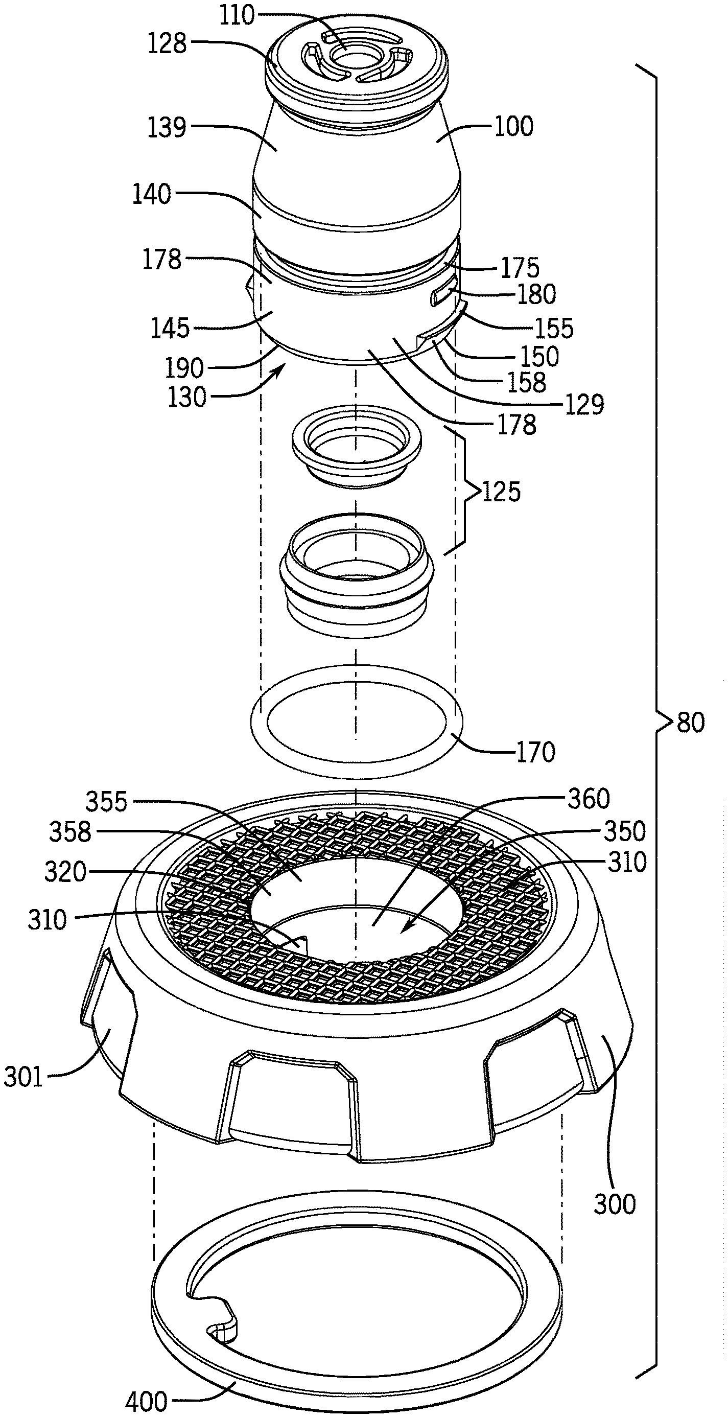
[0014] FIG. 4 is an exploded view of the lid assembly.
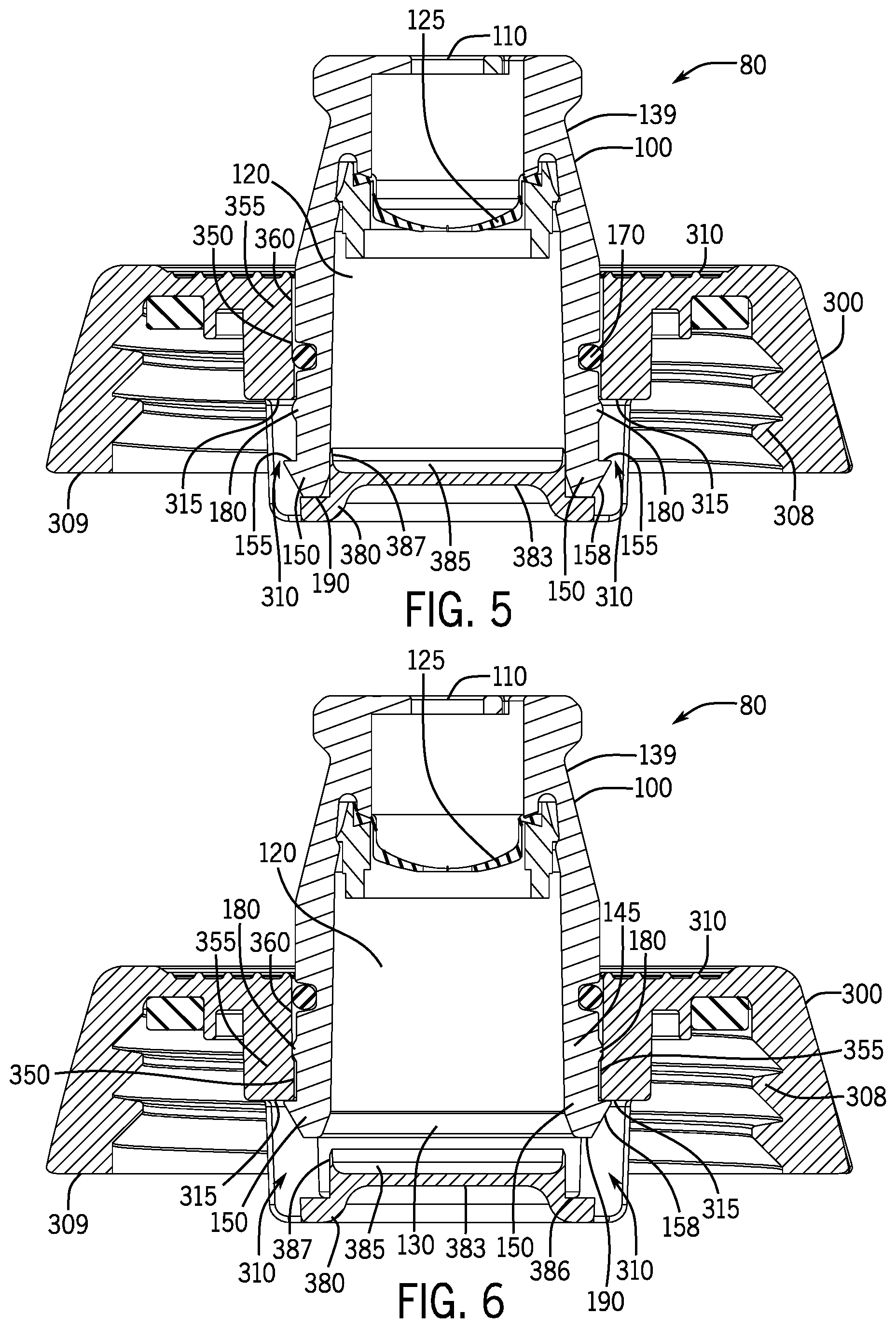
[0015] FIG. 5 is a sectional view of the lid assembly in the closed position.
[0016] FIG. 6 is a sectional view of the lid assembly in the open position.
[0017] FIG. 7 is a perspective sectional view of the lid base.
DETAILED DESCRIPTION
[0018] For purposes of this application, any terms that describe relative position (e.g., "upper", "middle" "lower", "outer", "inner", "above", "below", "bottom", "top", etc.) refer to an aspect of the invention as illustrated, but those terms do not limit the orientation in which the embodiments can be used.
[0019] A drinking bottle assembly 10 will now be described with reference to FIGS. 1-7. With reference to FIG. 1, the drinking bottle assembly 10 includes a bottle 50 and a lid assembly 80. The lid assembly 80 may engage to the bottle 50. With reference to FIGS. 2 and 3, the lid assembly 80 includes a lid core component 100 and a lid base 300.
[0020] In order to open the lid assembly 80, the lid core component 100 may be pulled or extended from the lid base 300 to an open position in order to permit liquid flow through the lid core component 100. A closed position of an aspect of the lid assembly 80 is shown in FIG. 5. The open position of the lid assembly 80 is shown in FIG. 6. In order to drink from the drinking bottle assembly 10, a user may pull on the lid core component 100 to extend the lid core component 100 relative to the lid base 300, and then the user may squeeze or tip the bottle 50 in order to urge liquid to flow from the bottle 50 through the lid core component 100.
[0021] The extension (or pulling) of the lid core component 100 relative to the lid base 300 uncovers or unblocks one, two, or more fluid openings 310 of the lid base 300 to permit fluid flow through the lid assembly 80. Similarly, the retraction (or pushing) of the lid core component 100 relative to the lid base 300 covers or blocks the one, two, or more fluid openings 310 of the lid base 300 to prevent fluid flow through the lid assembly 80.
[0022] The lid core component 100 is not generally removable from the lid base 300. The lid core component 100 includes one or more fastening members 150 that engage with an upper rim 315 of the fluid openings 310 to normally prevent removal of the lid core component 100 from the lid base 300. When the lid core component 100 has been extended to the fully open position, the one or more fastening members 150 engage or contact the upper rim 315 of the fluid openings 310 and physically block or prevent the further extension of the lid core component 100 from the lid base 300. The fastening members 150 catch against the upper rim 315 to limit the extending of the lid core component 100.
[0023] The lid core component 100 may be pushed or pressed to a closed position to reduce leakage or spillage from the bottle 50. The closed position is shown in FIG. 5. When fully closed, one or more projecting members 180 help to maintain the lid core component 100 in a closed position to prevent accidental or inadvertent opening of the lid assembly 80 of the drinking bottle assembly 10. The projecting members 180 are configured to releasably hold the lid core component 100 in the closed position.
[0024] The projecting members 180 extend or project from an outer surface 178 of the lid core component 100. The projecting members 180 may include one or more ridges, bumps, protrusions, etc. on the outer surface 178 of the lid core component 100. When the user desires to drink from the drinking bottle assembly 10, the user pulls the lid core component 100 from the lid base 300 with sufficient force to pull the projecting member 180 past the upper rim 315 of the fluid openings 310. The projecting member 180 and/or the lid core component 100 may slightly flex or deform to provide for the projecting member 180 to move past the upper rim 315. When the user desires to close the drinking bottle assembly 10, the user pushes the lid core component 100 into the lid base 300 with sufficient force to urge the projecting member 180 past the upper rim 315 of the fluid openings 310, which may create a tactile or audible sensation to the user that the lid core component 100 is fully closed. Once the lid core component 100 is fully closed, the projecting member 180 is past or below the upper rim 315, and a pulling or extending force is now normally required to once again open the lid core component 100. This reduces accidental opening of the lid core component 100.
[0025] The lid core component 100 will now be described. The lid core component 100 includes an inner passage 120 that fluidly connects a dispensing opening 110 and a lower opening 130 of the lid core component 100. The dispensing opening 110 is generally opposite of the lower opening 130. The dispensing opening 110 is at a distal portion of the lid core component 100 and provides for the liquid from within the drinking bottle assembly 10 to emit, such as by squirting, spraying, pouring, etc. from the lid core component 100. The lower opening 130 of the lid core component 100 receives liquid passing from the drinking bottle 50 through the lid base 300.
[0026] With reference to FIG. 4, the lid core component 100 may include a valve 125 contained in the inner passage 120 to further reduce leakage or spillage. The valve 125 may be formed from multiple components or include a single piece construction. In certain embodiments, the valve 125 might also help adjust the flow of the liquid out of the lid assembly 80 as well. For example, certain valves 125 may alternatively facilitate a fast squirt or a slow flow of liquid. The dispensing opening 110 is positioned in a liquid dispensing element 128, which is at or near an upper portion 139 of the lid core component 100. A lower portion 145 of the lid core component 100 includes the lower opening 130. A central portion 140 of the lid core component 100 is in between the upper portion 139 and the lower portion 145.
[0027] The lid core component 100 further includes the fastening member 150. The fastening member 150 may extend from the lower portion 145 of the lid core component 100. The fastening member 150 may also extend from an exterior side surface 129 of the lid core component 100. The fastening member 150 may include one or more ridges, protuberances, extending portions, etc. that operate with the lid base 300 to hold the lid core component 100 to the lid base 300.
[0028] In one aspect, as shown in FIG. 5, the fastening member 150 includes a catch surface 155 to catch against the upper rim 315 of the fluid openings 310. The catch surface 155 may extend in a generally perpendicular manner relative to the exterior side surface 129 of the lid core component 100. The fastening member 150 operates with the lid base 300 to hold the lid core component 100 to the lid base 300 in a moveable engagement. When the catch surface 155 hits or contacts the upper rim 315 of the fluid openings 310, the lid core component 100 cannot normally be extended any further, absent destructive techniques. In this aspect, the fastening member 150 includes a larger dimension or further extension from the outer surface 178 of the lid core component 100 as compared to a dimension or similar extension of the projecting member 180. As described above, the fastening member 150 provides a positive stop to the upward movement of the lid core component 100, while the projecting member 180 provides an audible or tactile sensation alerting the user that the lid core component 100 is closed and further assists in maintaining the lid core component 100 in the closed position.
[0029] As shown in FIG. 4, the lid core component 100 further includes a lid core component O-ring 170. The lid core component O-ring 170 may be held by a groove 175 in the outer surface 178 of the lid core component 100. The lid core component O-ring 170 seals against internal structures of the lid base 300. The outer surface 178 of the lid core component 100 may include a generally round shape (or other shapes in other aspects) with an outer diameter just smaller than an inner diameter 358 of an inner cylindrical passage 350 of the lid base 300. As described below, the inner cylindrical passage 350 of the lid base 300 receives the lid core component 100.
[0030] The lower portion 145 of the lid core component 100 further includes a bottom rim 190, which seals against the lid base 300 in the closed position of the lid assembly 80. The bottom rim 190 surrounds or is proximate to the lower opening 130. The bottom rim 190 may transition or be integral with the fastening member 150. In other aspects, the fastening member 150 is spaced from the bottom rim 190.
[0031] In this aspect, the bottom rim 190 is at a bottom portion of the lid core component 100. The catch surface 155 of the fastening member 150 is between the bottom rim 190 and the projecting member 180. In certain aspects, the fastening member 150 may include an angled surface 158 leading or transitioning into the catch surface 155. The angled surface 158 gradually angles outward from the outer surface 178 of the lid core component 100 and joins with the catch surface 155, which is generally perpendicular to the outer surface 178 of the lid core component 100. During assembly, the lid core component 100 may be inserted into the circular opening 320 of the upper wall 310 and further inserted into the inner cylindrical passage 350 until the fastening member 150 passes the upper rim 315. The angled surface 158 assists in wedging the fastening member 150 past the upper rim 315. The lid core component 100 and/or the lid base 300 may be made from flexible and resilient materials that allow some deformity or flexure during assembly.
[0032] The lid base 300 will now be described. The lid base 300 includes a generally circular side wall 305 that transitions into an upper wall 310. The side wall 305 may include one or more gripping surfaces 301. An interior surface of the side wall 305 includes an engagement member 308, such as threads, to engage with a complementary engagement member (such as threads) about or near a rim or upper opening of the bottle 50. The engagement member 308 may also include a snap-fit engagement, frictional engagement, bayonet engagement, or other engagements configured to selectively attach the lid base 300 to the bottle 50. The bottle 50 defines an interior to contain the liquid. In certain aspects, the bottle 50 may be formed from a resilient or flexible material, such as a plastic, that allows for squeezing of the bottle 50 to force the liquid from the bottle 50. In other aspects, the bottle 50 may be made from a material hard enough that it is not generally deformable by a human hand.
[0033] As shown in FIG. 4, the upper wall 310 of the lid base 300 further forms or defines the lid core receiving opening 320 configured as a circular opening. The lower opening 130 of the lid core component 100 passes through the circular opening 320. In other aspects, the lid core receiving opening 320 may be shaped as an oval, cylinder, square, hexagon, octagon or other polygon shape.
[0034] The lid base 300 further includes the inner cylindrical passage 350 that receives the lower portion 145 of the lid core component 100. The circular opening 320 of the upper wall 310 leads into the inner cylindrical passage 350, which is cylindrical in the illustrated aspect. The inner cylindrical passage 350 extends below the upper wall 310. The inner cylindrical passage 350 includes one or more cylindrical walls 355 having an inner diameter 358. The one or more fluid openings 310 are formed in or by the cylindrical walls 355. As shown in FIG. 3, the fluid openings 310 include an opening rim 312 that outlines the fluid openings 310. The fluid openings 310 are at least partially defined by the opening rim 312. The outer surface 178 of the lid core component 100 seals or closes against the opening rim 312 to further prevent fluid flow into the lid core component 100. In this aspect, the lid base 300 includes two fluid openings 310, although fewer or additional fluid openings 310 may be utilized.
[0035] The inner diameter 358 of the inner cylindrical passage 350 is sized to receive the lower portion 145 of the lid core component 100. As shown in FIG. 4, the cylindrical walls 355 form a sealing surface 360 that seals against the lid core component O-ring 170. When the lid core component 100 is pushed to a closed position, the lower portion 145 of the lid core component 100 is directed into the inner cylindrical passage 350.
[0036] The lid base 300 further includes a base portion 380. The base portion 380 is at a bottom of the cylindrical walls 355. The base portion 380 is between or joins the cylindrical walls 355 at a lower portion of the inner cylindrical passage 350. The base portion 380 includes or forms an upper sealing surface 383. The bottom rim 190 of the lid core component 100 seals against the upper sealing surface 383. The base portion 380 may be formed below a bottom rim 309 of the circular side wall 305, i.e., the cylindrical walls 355 may extend below the circular side wall 305.
[0037] When the lid assembly 80 is in a fully closed position, the bottom rim 190 of the lid core component 100 is urged against the upper sealing surface 383 of the base portion 380 in order to reduce leakage or spillage. The upper sealing surface 383 may include a rounded or protruding upper surface to promote sealing with the bottom rim 190. With respect to FIG. 7, in this aspect, the upper sealing surface 383 includes a recess 385 to improve sealing. A wall 387 is generally around the recess 385. The wall 387 may seal against an inner surface of the lower portion 145 of the lid core component 100. The upper sealing surface 383 may also include a circular sealing surface 386 (see FIG. 6) around the protruding upper surface 383 that is sized and shaped to seal with the bottom rim 190 of the lid core component 100. The circular sealing surface 386 may form a lower well around the protruding upper surface 383 that receives the bottom rim 190 of the lid core component 100.
[0038] In other aspects, the base portion 380 includes a separate gasket. For example, the base portion 380 may include an opening or groove which receives or holds the gasket. In this aspect, the bottom rim 190 seals against the gasket.
[0039] When the lid core component 100 is pulled or withdrawn from the lid base 300, the bottom rim 190 of the lid core component 100 distanced or moved from the sealing surface 383, thus allowing liquid to pass through the fluid openings 310, into the lower opening 130, and into the inner passage 120 of the lid core component 100.
[0040] As shown in FIG. 4, the lid assembly 80 may further include a lid gasket 400 to improve sealing between the lid assembly 80 and the bottle 50. The gasket 400 is removable from the lid assembly 80 to provide for thorough cleaning. Further, the 400 provides improved protection against accidental leakage or spillage when the drinking bottle assembly 10 is closed. Typical prior containers use plastic on plastic connections, which may be prone to leakage.
[0041] As such, it should be understood that the disclosure is not limited to the particular aspects described herein, but that various changes and modifications may be made without departing from the spirit and scope of this novel concept as defined by the following claims. Further, many other advantages of applicant's disclosure will be apparent to those skilled in the art from the above descriptions and the claims below.
* * * * *
D00000
D00001
D00002
D00003
D00004
D00005
XML
uspto.report is an independent third-party trademark research tool that is not affiliated, endorsed, or sponsored by the United States Patent and Trademark Office (USPTO) or any other governmental organization. The information provided by uspto.report is based on publicly available data at the time of writing and is intended for informational purposes only.
While we strive to provide accurate and up-to-date information, we do not guarantee the accuracy, completeness, reliability, or suitability of the information displayed on this site. The use of this site is at your own risk. Any reliance you place on such information is therefore strictly at your own risk.
All official trademark data, including owner information, should be verified by visiting the official USPTO website at www.uspto.gov. This site is not intended to replace professional legal advice and should not be used as a substitute for consulting with a legal professional who is knowledgeable about trademark law.