Container
Leng; Xiaojiao ; et al.
U.S. patent application number 16/421659 was filed with the patent office on 2020-05-14 for container. The applicant listed for this patent is Shenzhen Xinyuetang Plastic&Hardware Co., Ltd. Invention is credited to Xiaojiao Leng, Chunlei Wang.
| Application Number | 20200148429 16/421659 |
| Document ID | / |
| Family ID | 68504983 |
| Filed Date | 2020-05-14 |

| United States Patent Application | 20200148429 |
| Kind Code | A1 |
| Leng; Xiaojiao ; et al. | May 14, 2020 |
CONTAINER
Abstract
The present disclosure discloses a container including a container cap and a container body. The container body may be hollow, and an upper portion of the container body may be provided with an opening and a protruding portion. The height of a connecting region connecting the opening and the container body may be lower than the height of the protruding portion. The container cap may be coupled to the opening for sealing the opening. The protruding portion may be hollow, and a hollow portion of the container body may be in communication with a hollow portion of the protruding portion. When using the container of the present disclosure, liquid can be poured into the container through the opening. After use, the liquid in the container may be poured out or consumed so that it is light and easy to carry.
| Inventors: | Leng; Xiaojiao; (Shenzhen, CN) ; Wang; Chunlei; (Shenzhen, CN) | ||||||||||
| Applicant: |
|
||||||||||
|---|---|---|---|---|---|---|---|---|---|---|---|
| Family ID: | 68504983 | ||||||||||
| Appl. No.: | 16/421659 | ||||||||||
| Filed: | May 24, 2019 |
| Current U.S. Class: | 1/1 |
| Current CPC Class: | B65D 47/061 20130101; B65D 47/243 20130101; B65D 2547/06 20130101; B65D 23/003 20130101; A45F 3/18 20130101; B65D 21/0202 20130101; B65D 43/0231 20130101; B65D 25/22 20130101 |
| International Class: | B65D 47/06 20060101 B65D047/06; B65D 43/02 20060101 B65D043/02; B65D 23/00 20060101 B65D023/00; B65D 21/02 20060101 B65D021/02; A45F 3/18 20060101 A45F003/18 |
Foreign Application Data
| Date | Code | Application Number |
|---|---|---|
| Nov 13, 2018 | CN | 201821879787.3 |
Claims
1. A container comprising: a container cap; and a container body, the container body being hollow and an upper portion of the container body being provided with an opening and a protruding portion, wherein a height of a connecting region connecting the opening and the container body is lower than a height of the protruding portion, and the container cap is coupled to the opening for sealing the opening.
2. The container according to claim 1, wherein the protruding portion is provided only on one side of the opening.
3. The container according to claim 1, wherein a height of the opening is higher than the height of the connecting region connecting the opening and the container body, the height of the opening is higher than, equal to, or lower than the height of the protruding portion.
4. The container according to claim 1, wherein the protruding portion is hollow, and a hollow portion of the container body is in communication with a hollow portion of the protruding portion.
5. The container according to claim 1, wherein the container body further comprises at least one supporting column connecting two opposite sides of the container body.
6. The container according to claim 1, wherein the container cap further comprises a screw cap, a sleeve and an inner shaft, the inner shaft being located along an axis of the screw cap and the sleeve, wherein a diameter of the inner shaft is smaller than a diameter of the sleeve, and the diameter of the sleeve is smaller than a diameter of the screw cap.
7. The container according to claim 6, wherein the container cap further comprises a container mouthpiece, the container mouthpiece further comprises a liquid-discharging tube, and the liquid-discharging tube comprises a suction head and an elastic ring, wherein the suction head is located at an end portion of the liquid-discharging tube, and the liquid-discharging tube is sleeved on an outer side of the inner shaft and coupled to an inner wall of the sleeve by the elastic ring, to thereby render damping movement of the container mouthpiece inside the sleeve.
8. The container according to claim 7, wherein when the container is in a sealed state, a height of the container mouthpiece is lower than the height of the protruding portion, or equal to the height of the protruding portion, and when the container mouthpiece is pulled out, the container is in an open state, and the height of the container mouthpiece is higher than the height of the protruding portion.
9. The container according to claim 7, wherein an inverted hook is further provided on an end of the liquid-discharging tube opposite to the suction head, and a sealing plate and a retaining ring are further provided on the screw cap, and when the container mouthpiece is sleeved on the outer side of the inner shaft and mounted within the sleeve, the inverted hook is located between the sealing plate and the retaining ring.
10. The container according to claim 9, wherein the suction head is formed with a suction hole, when the container mouthpiece is moved to the sealing plate, the inner shaft just passes through the suction hole for sealing the suction hole.
11. The container according to claim 1, wherein the container body is further provided with a hanging hole for hanging of the container.
12. The container according to claim 1, wherein one side of the container body of the container has a recessed surface and the other side has a projected surface, and when two containers are stacked together, the projected surface of one of the containers is snap-fitted into the recessed surface of the other one of the containers.
Description
CROSS REFERENCE TO RELATED APPLICATIONS
[0001] The present application claims the benefit of Chinese Patent Application No. 201821879787.3 filed on Nov. 13, 2018, the contents of which are incorporated herein by reference in their entirety.
TECHNICAL FIELD
[0002] The present disclosure relates to a container, and in particular to a multi-functional container.
BACKGROUND TECHNOLOGY
[0003] With the improvement of living standards, more and more people choose to go outdoors. In order to keep fresh fruits, vegetables, beverages, beer and other foods or drinks, people often place some ice packs or ice boxes around or in the middle of the food or drinks. However, after these ordinary ice packs or ice boxes are used, their weight will not be reduced and they are heavy to carry.
SUMMARY
[0004] In view of the existing problem in the above prior art, an object of the present disclosure is to provide a container which is simple and reasonable in structure and easy to carry.
[0005] In order to achieve the above object, a container provided by the present disclosure may include a container cap and a container body. The container body may be hollow, and an upper portion of the container body may be provided with an opening and a protruding portion. The height of a connecting region connecting the opening and the container body may be lower than the height of the protruding portion. The container cap may be coupled to the opening for sealing the opening. The protruding portion may be hollow, and a hollow portion of the container body may be in communication with a hollow portion of the protruding portion. This can ensure that when a user is filling up the container with a liquid, it is difficult for the user to completely fill up the container so that a space can be reserved for liquid expansion. Thus, the container cannot be easily damaged and can be used repeatedly.
[0006] As a specific embodiment, the protruding portion may be provided only on one side of the opening. The opening may have two sides on the container body. When the liquid is poured into the container body through the opening, the height of the opening may be lower than the height of the protruding portion of only one side of the opening. This can facilitate drinking of water by the user.
[0007] Furthermore, the container cap may further include a container mouthpiece. The container mouthpiece may further include a liquid-discharging tube, and the liquid-discharging tube may include a suction head and an elastic ring. The suction head may be located at an end portion of the liquid-discharging tube. The liquid-discharging tube may be sleeved on an outer side of the inner shaft and coupled to an inner wall of the sleeve by the elastic ring, to thereby render damping movement inside the sleeve.
[0008] Furthermore, an inverted hook may be provided on an end of the liquid-discharging tube opposite to the suction head. A sealing plate and a retaining ring may be further provided on the screw cap. When the container mouthpiece is sleeved on the outer side of the inner shaft and mounted within the sleeve, the inverted hook can be located between the sealing plate and the retaining ring.
[0009] Furthermore, to facilitate carrying of the container, the container body may be further provided with a hanging hole for hanging of the container.
[0010] Furthermore, one side of the container body of the container may have a recessed surface and the other side may have a projected surface. When two containers are stacked together, the projected surface of one of the containers can be snap-fitted into the recessed surface of the other one of the containers.
[0011] Compared to the prior art, the container of the present disclosure has the following beneficial technical effects. The containers of the prior art are often sealed. When the ice in the container turns into liquid, the weight of the container does not reduce and the container is heavy to carry. After the container of the present disclosure is used, a user can pour the liquid out or drink the liquid so that the container is light to carry. In addition, since the height of the connecting portion connecting the opening of the container and the body of the container is lower than the height of the protruding portion of the container body, this can ensure that it is difficult for the user to completely fill up the container with liquid, and a space is reserved for expansion of the liquid. Therefore, the container cannot be easily damaged and can be used repeatedly.
[0012] For a better understanding and implementation, the present disclosure will be described below in detail in conjunction with the accompanying drawings.
BRIEF DESCRIPTION OF THE DRAWINGS
[0013] FIG. 1 is a front view of the container according to an embodiment of the present disclosure;
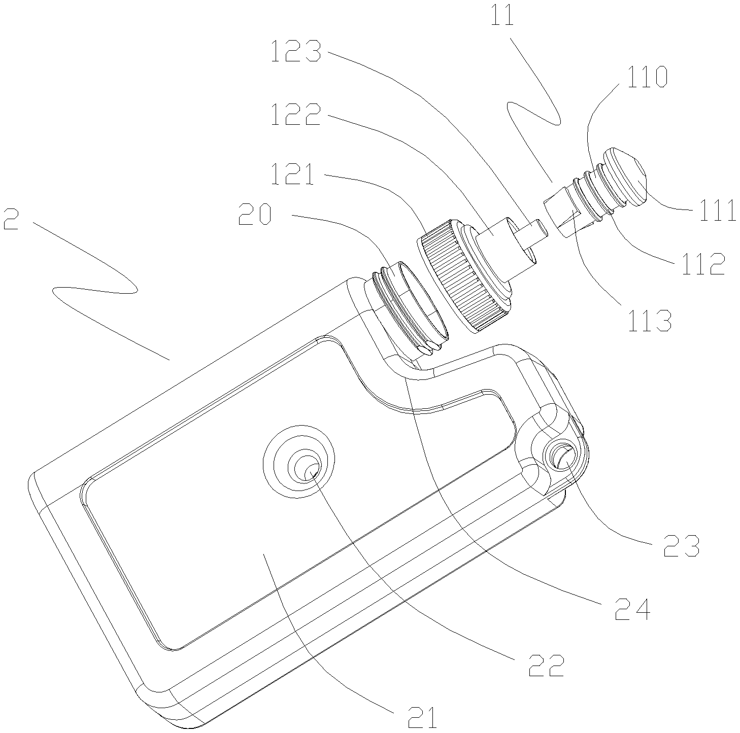
[0014] FIG. 2 is an exploded view of the container according to an embodiment of the present disclosure;
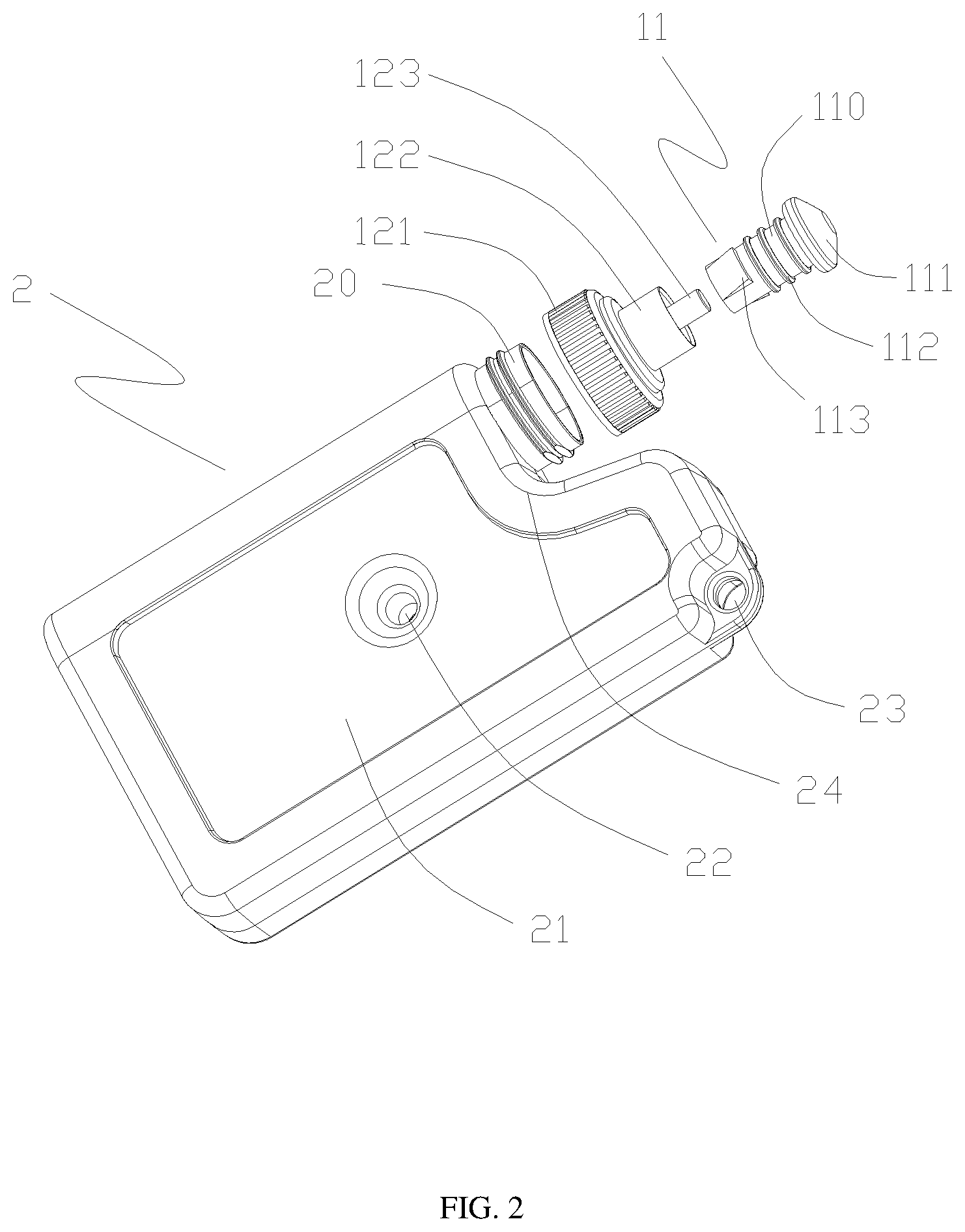
[0015] FIG. 3 is a side view of the container according to an embodiment of the present disclosure;
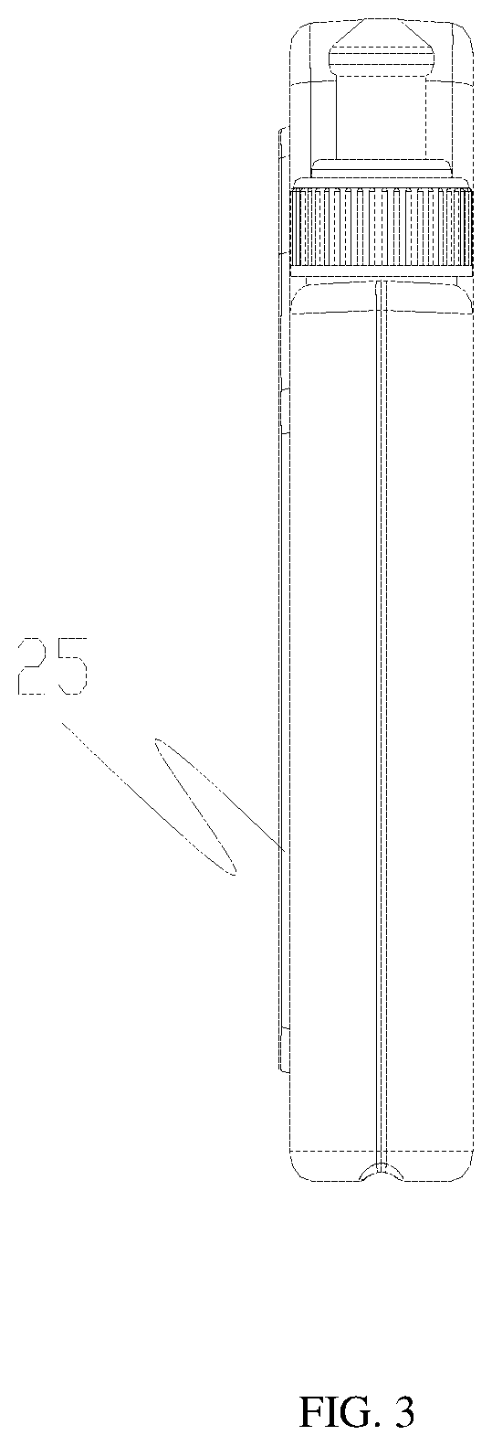
[0016] FIG. 4 is a perspective view of the container cap according to an embodiment of the present disclosure;
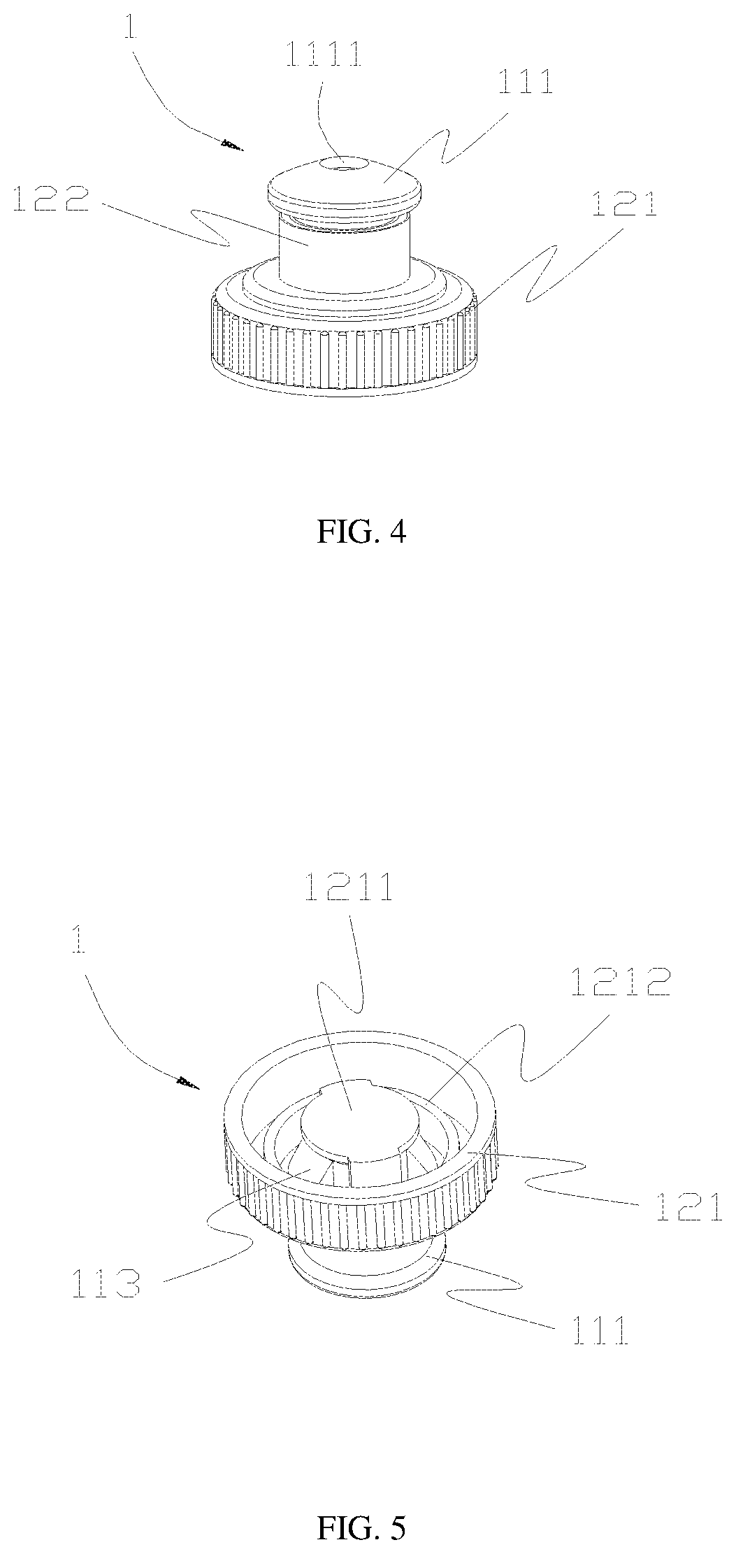
[0017] FIG. 5 is a perspective view from another viewing angle of the container cap according to an embodiment of the present disclosure; and
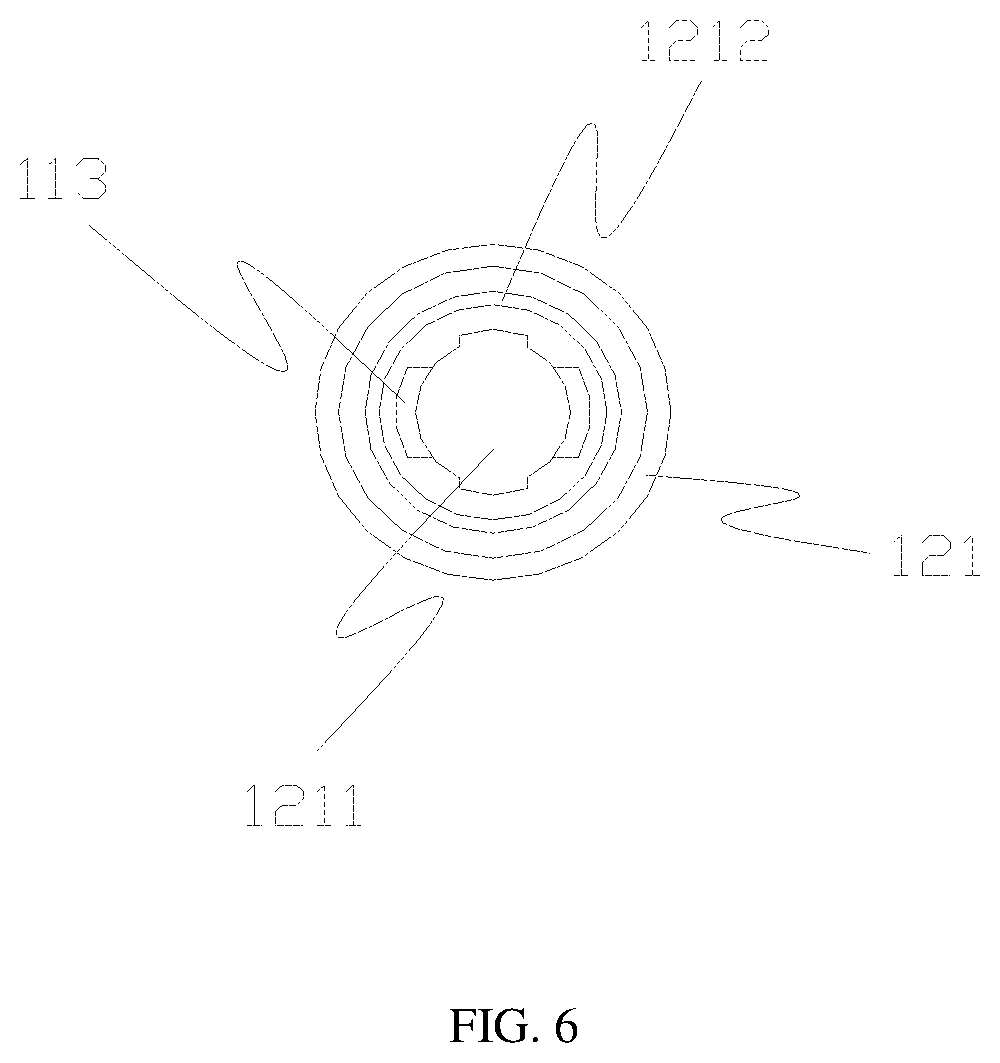
[0018] FIG. 6 is a plan view of the container cap according to an embodiment of the present disclosure;
TABLE-US-00001 [0019] Reference numerals in the accompanying drawings: Container cap 1; Container mouthpiece 11; Liquid-discharging tube 110; Suction head 111; Suction hole 1111; Elastic ring 112; Inverted hook 113; Screw cap 121; Sealing plate 1211; Retaining ring 1212; Sleeve 122; Inner shaft 123; Container body 2; Opening 20; Recessed surface 21; Supporting column 22; Hanging hole 23; Arc-shaped region 24; Projected surface 25.
DETAILED DESCRIPTION OF THE EMBODIMENTS
[0020] Referring to FIG. 2 and FIG. 4 which show an embodiment of the container of the present disclosure, the container may include a container cap 1 and a container body 2. The container body 2 may be hollow. An upper portion of the container body 2 may be provided with an opening 20 and a protruding portion. The number of the opening 20 may be one or more. Liquid can be poured into the container body 2 through the opening 20. The height H3 of a connecting region connecting the opening 20 and the container body 2 may be lower than the height H2 of the protruding portion. The container cap 1 may be coupled to the opening 20 for sealing the opening 20.
[0021] The containers of the prior art are often sealed. When the ice in the container turns into liquid, the weight of the container does not reduce and the container is heavy to carry. When using the container of the present disclosure, a user can fill the container with liquid through an opening 20. After the container of the present disclosure is used, the user can pour out the liquid or drink the liquid so that the container is light to carry.
[0022] In order to prevent overfilling of liquid in the container when a user is using the container and causing the container to expand and burst when placed in a freezer compartment, referring to the embodiment of the present disclosure in FIG. 1, the height H3 of the connecting region connecting the opening 20 and the container body 2 is designed to be lower than the height H2 of the protruding portion. The height of the opening 20 may be higher than the height H3 of the connecting region connecting the opening 20 and the container body 2. Furthermore, the height H1 of the opening 20 may be higher than, equal to, or lower than the height H2 of the protruding portion. The protruding portion may be hollow. A hollow portion of the container body may be in communication with a hollow portion of the protruding portion. This can ensure that when a user is filling up the container with a liquid, it is difficult for the user to completely fill up the container so that a space can be reserved for liquid expansion. Thus, the container cannot be easily damaged and can be used repeatedly.
[0023] In addition to the function of an ice box, the container of the present embodiment can be used as a water bottle. The water bottle can be used to carry a variety of liquids, including water, beverages and wine, etc. For the sake of description, water is used as an example in the following description. Referring to FIG. 1, the opening 20 of the container body 2 has two sides, i.e., side A and side B. If both sides of the opening 20 are protruding, it is inconvenient for the user to drink the water inside the container through the opening. In the present disclosure, a protruding portion is only provided on one side of the opening (for example, side B shown in FIG. 1). This arrangement will not affect the drinking of the water inside the container, and it is difficult for the user to completely fill up the container with liquid. The region between the opening 20 or the connecting region connecting the opening 20 and the container body 2 and the highest point of the container body 2 may be an arc-shaped region 24 or folding line-shaped region.
[0024] Furthermore, in order to ensure that the container will not deform after placing inside a freezer compartment, as shown in FIG. 2, the container of the present embodiment may further include at least one supporting column 22 connecting two opposite sides of the container body. Although only one supporting column 22 is shown in FIG. 2, in practice there may be a plurality of supporting columns, and the present disclosure is not limited to the present embodiment.
[0025] After the container is filled with liquid, in order to seal the container, the container may further include a container cap 1. The number of the container cap 1 is the same as the number of the opening 20. As shown in FIG. 2 and FIG. 4, the container cap 1 may at least include a screw cap 121. The screw cap 121 and the opening 20 may be screwed together, or they may be snap-fitted together or sleeved together, etc. In the present embodiment, screw connection is described as an example. In addition, the container cap may further include a sleeve 122 and an inner shaft 123. The inner shaft 123 may be located along an axis of the screw cap 121 and the sleeve 122. The diameter of the inner shaft 123 may be smaller than the diameter of the sleeve 122, and the diameter of the sleeve 122 may be smaller than the diameter of the screw cap 121. The screw cap 121, the sleeve 122 and the inner shaft 123 may be integrally formed or they may be three independent components, and is not limited by the present embodiment.
[0026] When the container of the present embodiment is used as a water bottle, in order to facilitate the drinking of liquid in the container, referring to FIG. 2, the container cap 1 may further include a container mouthpiece 11. The container mouthpiece 11 may at least include a liquid-discharging tube 110. The liquid-discharging tube 110 may include a suction head 111 and an elastic ring 112 to facilitate drinking of water. As shown in FIG. 2, the suction head 111 may be located at an end portion of the liquid-discharging tube 110. The liquid-discharging tube 110 may be sleeved on an outer side of the inner shaft 123 and coupled to an inner wall of the sleeve 122 by the elastic ring 112, to thereby render damping movement of the container mouthpiece 11 inside the sleeve 122. When it is necessary to drink water, the container mouthpiece 11 can be pulled out from the sleeve 122 in a direction along the axis of the inner shaft 123. When there is no need to drink water, the container mouthpiece 11 of the container can be pushed back into the sleeve 122 in the direction along the axis of the inner shaft 123.
[0027] In order to allow the container mouthpiece 11 to move within a limited range and prevent the container mouthpiece 11 from being pulled out of the sleeve 122, as shown in FIGS. 2 and 5, an inverted hook 113 may be provided on an end of the liquid-discharging tube 110 opposite to the suction head 111, and a sealing plate 1211 and a retaining ring 1212 may be provided on the screw cap 121. Referring to FIG. 6, when the container mouthpiece 11 is sleeved on the outer side of the inner shaft 123 and mounted within the sleeve 122, the inverted hook 113 can be located between the sealing plate 1211 and the retaining ring 1212. When the container mouthpiece 11 moves in the direction of the axis of the inner shaft 123 toward the retaining ring 1212 to the retaining ring 1212, since the inner diameter of the retaining ring 1212 is smaller than the diameter of the inverted hook 113, it can prevent the container mouthpiece 11 from moving continuously forward, so that the container mouthpiece 11 cannot be pulled out of the sleeve 122.
[0028] When the container mouthpiece 11 is moved in the direction of the axis of the inner shaft 113 toward the sealing plate 1211 to the sealing plate 1211, the sealing plate 1211 can also prevent the container mouthpiece 11 from moving continuously in this direction. It can be seen that the distance between the sealing plate 1211 and the retaining ring 1212 can be greater than the length of the inverted hook 113 in the axial direction of the inner shaft. Thus, the container mouthpiece 11 can only be moving between the sealing plate 1211 and the retaining ring 1212 due to the restriction of the inverted hook 113.
[0029] When the container mouthpiece 11 is moved to the sealing plate 1211, the inner shaft 123 just passes through a suction hole 1111 formed on the suction head 111 (as shown in FIG. 4) for sealing the suction hole 1111.
[0030] Referring to FIGS. 1 and 3, when the container is in a sealed state, the height of the container mouthpiece 11 may be lower than the height of the protruding portion, or equal to the height of the protruding portion. When drinking water is needed, a portion of the container mouthpiece 11 can be pulled out. At this time, the container is in an open state, and the height of the container mouthpiece 11 may be higher than the height of the protruding portion to facilitate drinking of water by the user.
[0031] Furthermore, in order to facilitate carrying, the container body 23 may be provided with a hanging hole. When in use, a user can attach a rope to the hanging hole, and hang the container on a backpack or a bicycle, etc.
[0032] In order to facilitate transportation or carrying a number of containers at the same time, one side of the container body 2 of the container may have a recessed surface 21 (as shown in FIG. 2), and the other side may have a projected surface 25 (as shown in FIG. 3). The position and dimension of the recessed surface 21 and the projected surface 25 may be substantially the same. When two containers are stacked together, the projected surface 25 of one of the containers can be snap-fitted into the recessed surface 21 of the other one of the containers.
[0033] The above is a description of the embodiments of the present disclosure, but the present disclosure is not limited to the above embodiments. Various modifications or variations of the present disclosure made without departing from the spirit and scope of the present disclosure should also be within the scope of protection of the present disclosure.
* * * * *
D00000
D00001
D00002
D00003
D00004
D00005
XML
uspto.report is an independent third-party trademark research tool that is not affiliated, endorsed, or sponsored by the United States Patent and Trademark Office (USPTO) or any other governmental organization. The information provided by uspto.report is based on publicly available data at the time of writing and is intended for informational purposes only.
While we strive to provide accurate and up-to-date information, we do not guarantee the accuracy, completeness, reliability, or suitability of the information displayed on this site. The use of this site is at your own risk. Any reliance you place on such information is therefore strictly at your own risk.
All official trademark data, including owner information, should be verified by visiting the official USPTO website at www.uspto.gov. This site is not intended to replace professional legal advice and should not be used as a substitute for consulting with a legal professional who is knowledgeable about trademark law.