Pipeline Exterior Blasting System
PARTRIDGE; JONATHAN ; et al.
U.S. patent application number 16/683257 was filed with the patent office on 2020-05-14 for pipeline exterior blasting system. This patent application is currently assigned to ROBOTIC GRIT BLASTER, LLC. The applicant listed for this patent is JONATHAN STARKWEATHER PARTRIDGE. Invention is credited to JONATHAN PARTRIDGE, MICHAEL W. STARKWEATHER.
| Application Number | 20200147757 16/683257 |
| Document ID | / |
| Family ID | 70551605 |
| Filed Date | 2020-05-14 |


| United States Patent Application | 20200147757 |
| Kind Code | A1 |
| PARTRIDGE; JONATHAN ; et al. | May 14, 2020 |
PIPELINE EXTERIOR BLASTING SYSTEM
Abstract
A pipeline exterior blasting system, movably mounted to a pipeline, to blast only uncoated end sections of a first and second pipe at a weld site where the first and second pipes were welded together. Uniquely, there is a blasting containment device having: a fixed portion 22; a rotating containment portion 24 rotatably mounted to the fixed portion 22, and releasably and rotatively coupled to the second pipe 20B; a support devices system 106, coupled to the blasting containment device 12 via connections 107, including: a blasting device 16, a vacuum device 18; and an electrical power generator 14. Finally, there is a lateral movement system, coupled to the blasting containment device 12, having: a first position that holds the grit blasting containment device 12 in a fixed position as the grit blasting containment device blasts particles circumferentially around the two pipes; a second position that moving the grit blasting containment device off of the two pipes; and a third position that provides movement of the grit blasting containment device along the two pipes.
| Inventors: | PARTRIDGE; JONATHAN; (SPANISH FORK, FL) ; STARKWEATHER; MICHAEL W.; (TAMPA, FL) | ||||||||||
| Applicant: |
|
||||||||||
|---|---|---|---|---|---|---|---|---|---|---|---|
| Assignee: | ROBOTIC GRIT BLASTER, LLC Tampa FL |
||||||||||
| Family ID: | 70551605 | ||||||||||
| Appl. No.: | 16/683257 | ||||||||||
| Filed: | November 13, 2019 |
Related U.S. Patent Documents
| Application Number | Filing Date | Patent Number | ||
|---|---|---|---|---|
| 62766993 | Nov 14, 2018 | |||
| Current U.S. Class: | 1/1 |
| Current CPC Class: | B24C 3/32 20130101; B24C 3/06 20130101; B24C 5/04 20130101; B24C 1/04 20130101 |
| International Class: | B24C 3/32 20060101 B24C003/32; B24C 1/04 20060101 B24C001/04; B24C 3/06 20060101 B24C003/06 |
Claims
1. A pipeline exterior blasting system 10, movably mounted to a pipeline 20, to blast only uncoated end sections of a first and second pipe 20A and 20B at a weld site where the first and second pipes were welded together, comprising: a) a blasting containment device 12 having: i) a fixed portion 22, having: a. a releasable holder 66 that releasably attaches to the first pipe 20A, to hold the fixed portion 22 in position during blasting operation; b. a motor 40, coupled to the fixed portion 22; c. a linkage system 42, 44, 46, 50, with one end coupled to the motor 40; ii) a rotating containment portion 24 rotatably mounted to the fixed portion 22, and releasably and rotatively coupled to the second pipe 20B; having: a. a linkage engagement portion 48, coupled to a second end of the linkage system 42, 44, 46, 50; b. a blasting nozzle 27, directed at the weld site; c. a vacuum hose 38, oriented to suck out airborne dust; d. a support device 68, abutting to the second pipe 20B, positioned to rotatively move around the second pipe as the rotating containment portion 24 circumferentially moves around the second pipe; b) a support devices system 106, coupled to the blasting containment device 12 via connections 107, including: i) a blasting device 16, coupled to the blasting containment portion 22 via a blasting material delivery hose 36 and the material blasting nozzle 27, to enable delivery of blasting material 72 to the material blasting nozzle 27 at high air pressure and speed, and thereby impacting the weld site 11 with the blasting material 72; ii) a vacuum device 18, coupled to the blasting containment device 12, via a vacuum port 37, to enable resulting dust 62 to be vacuumed out of the blasting containment device after impacting the weld site 11 with the blasting material 72; and iii) an electrical power generator 14, electrically coupled via electrical cord 34 to the grit blasting containment device 12, the grit blasting device 16, and the grit vacuum device 18 to enable electrical power to be provided thereto; and c) a lateral movement system, coupled to the blasting containment device 12, having: iv) a first position that holds the grit blasting containment device 12 in a fixed position as the grit blasting containment device blasts particles circumferentially around the two pipes; v) a second position that moving the grit blasting containment device off of the two pipes; and vi) a third position that provides movement of the grit blasting containment device along the two pipes.
2. The system of claim 1, wherein the lateral movement system includes: a) a first and second releasable holder devices 35, mounted to the fixed portion 22 and rotating containment portion 24 respectively; b) a connector 33, inserted through the releasably first and second holder devices 35; and c) a vehicle 100 with a lifting device 101 that is releasably couplable to the connector 35.
3. The system of claim 1, wherein lateral movement device includes a remote controlled vehicle 170, coupled to the grit blasting containment device 12, and positioned on a top portion of the pipeline 20 during movement thereof, having a carriage 175, movable into a first position that moves the grit blasting containment device 12 along the pipeline 20.
4. The system of claim 3, further includes: a) a camera 133, mounted to the rotatable containment portion 24 oriented to send real time images of the pipeline 20 relative positioning thereto, and to enable proper alignment of the blasting nozzle 27 with the welding site 11; and b) a remote viewing system 200, in controlling communication with the remote controlled vehicle 170, sending controlling signals to the remote controlled vehicle 170 to move the grit blasting containment device 12 forward and backward along the pipeline 20.
5. A method 150 of progressive welding, cleaning and coating a pipeline, comprising the steps of: a) providing at least a first, second, third, and forth pipe, each progressively lined up end to end, wherein the site of the first and second abutting pipe ends 111 are not welded, the site of the second and third abutting pipe ends 11 are welded, and the site of the third and forth abutting pipe ends 122 are welded and cleaned; b) providing a welding system 110 at the site of the first and second abutting pipe ends 111; c) providing a blasting containment device 12 at the site of the second and third abutting pipe ends 11, that is removably coupled around the second and third pipe ends 11; d) providing a pipe protective coating application system 120 at the site of the third and forth abutting pipe ends 122; d) providing a blasting containment device moving system; e) welding the first and second abutting pipe ends with the welding system 110; f) blasting the second and third abutting pipe ends 11 with the blasting containment device 12 without allowing dust from the blasting to escape from the blasting containment device 12; g) coating the third and forth abutting pipe ends 122 using the pipe protective coating application system 120; and h) after completing the welding, blasting and coating steps, performing the following steps: i) releasing the blasting containment device 12 from being coupled around the second and third pipe ends 11; ii) moving the welding system 110 to a subsequent site where two subsequent pipe ends are not welding together; iii) moving the blasting containment device 12, via the blasting containment device moving system, to a subsequent site where two subsequent pipe ends are welded together but not coated by the pipe protective coating application system 120; and iv) moving the pipe protective coating application system 120 to a subsequent site where two subsequent pipe ends were previously welded together and previously blasted by the blasting containment device 12.
6. The method of claim 5, wherein the blasting containment device moving system includes a vehicle with a boom arm coupled to a cable attached to the blasting containment device 12.
7. The method of claim 5, wherein the blasting containment device moving system includes a remote control vehicle mounted above the pipeline 20 and coupled to the blasting containment device 12.
8. The method of claim 7, wherein the blasting containment device 12 is coupled to a support system 106 having: a power system 14, a blasting material delivery system 16, and a vacuum system 18.
Description
CROSS REFERENCE TO RELATED APPLICATION
[0001] This application claims the benefit of copending U.S. Provisional Application No. 62/766,993, having the at least one inventor in common, filed Nov. 14, 2018, titled: "THE ROBOTIC GRIT BLASTER."
BACKGROUND OF THE INVENTION
(1) Field of the Invention
[0002] This invention relates generally to the field of robotic grit blasting tool, and more particularly to a system and device for automatically blasting the welded site of a pipeline or two pipes with blast material, to clean and prepare the surface prior to coating that portion of the pipe with an environmental protective coating layer, and blasting without contaminating the surrounding work site with the grit material and unwanted dust, and providing a safer work site for workers by eliminating the need to wear full hazardous containment suits to perform such blasting operations.
(2) Background of the Invention
[0003] The present invention relates generally to the field of robotic grit blasting tool, and more particularly to a device for automatically blasting the welded site of a pipe with grit material to clean and prepare the surface prior to coating the pipe with a environmental protective coating layer without contaminating the work site with the grit material and providing a safer work site by eliminating the workers need to wear full hazardous containment suits.
[0004] It is well known that pipeline are often buried in the ground for many years, which expose the iron based pipe to environmental conditions that often will cause an eroding of the pipe due to rusting and oxidation effects. Therefore, when initially building a pipeline, the individual pipe sections are typically coated with a protective coating prior to shipment to the work site, where they are welded together to for the continuous pipeline. By coating the pipe sections prior to the shipment, it is possible to coat the majority of the pipe, often being 60 feet or so. However, it is found that the coating material will interfere with the welding process taking place at the ends of the pipes, so those portions, from 2 to 24 inches at each end of the pipe, are typically left exposed and not coated prior to shipment. As a result, the now welded ends of the pipe must be coated to protect the complete pipe from the deleterious effects from the environmental oxidation, corrosion and rusting effects. However, prior to applying the last coating of the pipe ends, the exposed pipe sections must be cleaned after the welding process to remove any oxidation and rusting and to rough up or pit the surface of the pipe to increase the surface area and create holding spots for the coating material to adhere to in an effective manner.
[0005] The common process for preparing the welded pipe ends is currently complex and hazardous to the environment and toxic to the workers. For example, and as a first step of the blasting process of the welded pipe sections, the work site must be completely sectioned off from the surrounding environment to prevent any of the hazardous blasting material and dust from freely becoming airborne and contaminating a large areas or exposing workers respiratory air tracts to the hazardous aerosol and carcinogenic contaminants. Wherein, erecting a tent around the selected welded pipe sections typically is undertaken. This tent erection and takedown step will take a great deal of employee time. It is noted that to just complete on mile of pipeline, there may be 100 weld sites or more. A typical pipeline may extend for hundreds or thousands of miles, requiring tens of thousands of tent erection and take down processes.
[0006] Next, the workers must be completely protected from coming in contact to the hazardous materials, including skin contact and respiratory airways. This step requires each worker to don a complete head to toe hazardous material (haz-mat) protection suit. These "haz-mat" suits make it difficult for the workers to do their job in that they are cumbersome and create a very hot personal space for the workers, especially during sunny days where the ambient temperatures may reach 90 to 110 degrees Fahrenheit.
[0007] Now that the selected individual pipe weld site is contained and the workers are properly protected, the blasting equipment must be oriented, positioned and activated. Specifically, the typical blasting equipment often includes a power source, a hopper for holding the blasting material, a blasting air compressor pump, a long hose with a nozzle, there may be other parts like individual motors and hoppers, and electrical wiring and controllers which are not detailed at this time.
[0008] Now that the blasting equipment, site contamination tent, and worker protections are in place, the blasting process is now ready to take place. This is assuming that the pipe weld section has all along been elevated about the ground usually one to two feet. Now the worker takes the blasting nozzle into the tent and begins to blast the individual pipe weld section. This process entails the worker directing the nozzle all around the complete circumference of the pipe weld section. Given that the worker is in a confined space, which is now being filled with a thick cloud of blasting dust that is exiting the nozzle at 100 to 1600 lbs. of pressure (psi), the worker is responsible to provide a completely uniform circumferential cleaning of the pipe welded section. This operation requires both visual inspect as the work advances, and to specifically inspect not only the sides and top, but also the bottom section of the pipe, which is only one to two feet above ground, and requires the worker to get on their hands and knees each time on each side of the pipe to inspect the cleaning quality all while wearing a haz-mat suit that has restricted visual capabilities or flexibility. In short, one can imagine that it is very difficult to achieve a consistent high quality blast cleaning product under these conditions in a single blasting of an individual pipe weld section, let alone repeat this process consistently for tens of thousands of operations.
[0009] One might imagine that the process is now complete, but they would be mistaken; the cleanup process must now take place. Ideally, the blast material is contained in the tent, but now the hazardous blast material is now all over the ground under the tent. So the tent must now be taken down, and the ground under the tent must now be decontaminated by removing all the hazardous material from the ground. This removal is typically done by workers, still wearing haz-mat suits, taking shovels and digging up the ground and placing the contaminated ground in a haz-mat disposal bag; whereby the haz-mat bags are then loaded onto trucks and transported to approved costly disposal sites.
[0010] Therefore, it s now clear and obvious that the current methods and took used in cleaning the welded pipe sections is time consuming, and adds great costs to the overall pipeline construction project. Further, pipeline blasting is also fraught with unsafe and hazardous working conditions. Additionally, the overall goal of achieving consistent and uniform quality cleaning and the pipeline coating preparation is completely out of quality control by any process engineering guidelines.
[0011] As such, there has been demonstrated that there is a great need for a new system and tool that is capable of eliminating the afore described problems with the cleaning of the welded pipe sections. Specifically, there is described hereinafter a new inventive process and tool that would work without detrimentally impacting the environment, without subjecting workers to unsafe and hazardous working conditions, allowing the process to take less overall time and expense, providing a consistent quality of cleaning and surface preparation for thousands of applications, and prevent environmental contamination and eliminate the ground cleaning operations.
[0012] The following patents and applications are presented for background purposes, and are herein incorporated by reference for their supportive teachings to support the present invention, which review hereof would easily assist and enable one skilled in the art to more easily understand the potential operations of various aspects of the presently described invention, in which:
[0013] U.S. Pat. No. 5,398,461, issued Mar. 21, 1995 to Rose, entitled Apparatus and method for cleaning a pipeline, teaches of an apparatus for cleaning the outer surface of a pipeline including a self propelled carriage supported on the pipeline for movement.
[0014] U.S. Pat. No. 5,458,683, issued Oct. 17, 1995 to Taylor et al., entitled Device for surface cleaning, surface preparation and coating applications, discloses a pipeline treating apparatus that has a pair of pivotally mounted housing sections and a pair of separately pivotal nozzle frames.
[0015] U.S. Pat. No. 9,415,426, issued Aug. 16, 2016 to Blake et al. entitled Pipe cleaning apparatus, discloses a pipe cleaning apparatus with a support frame having an elongated carriage frame member, at least one pipe blasting assembly carried by the carriage frome member of the apparatus support frame and including an assembly carriage carried by the carriage frame member.
[0016] U.S. Pat. No. 1,815,573, issued Jul. 21, 1931 to McManis, entitled Device for cleaning the outside of pipes, disclose an apparatus for cleaning and removing rust, scale and other corrosion and foreign matter adhering to the outside of pipes.
[0017] U.S. Pat. No. 2,460,989, issued Feb. 8, 1949 to Kramer, entitled a Pipe cleaning machine, discloses a machine for cleaning metal pipe where it is desired to remove mill scale, rust or portions of previously applied coating material.
[0018] U.S. Pat. No. 4,603,516, issued Aug. 5, 1986, to Hoffman, entitled Self propelled pipe blast cleaner capable of travel along a pipeline supported over the ditch, teaches of a device that continuously blast cleans the outside of the pipe in advance of pipe coating or wrapping.
[0019] U.S. Pat. No. 5,199,226, issued Apr. 6, 1993 to Rose, entitled a Method and apparatus for removing outer coatings from pipe, discloses a coating removal machine for a pipe that has an enclosed housing extending about front and rear tool carriers, which rotate in opposite directions about the pipe and have coating removal tools for removing the coating material from the pipe.
[0020] U.S. Pat. No. 4,333,277, issued Jun. 8, 1982 to Tasedan, entitled Combination sand-blasting and vacuum apparatus, which teaches providing a sand blasting gun having an air inlet passage and a sand inlet passage and a vacuum chamber coupled to the end of the sand blasting gun therein to thereby suck the sand out of the vacuum chamber and through a sand outlet passage to a sand storage container.
[0021] U.S. Pat. No. 5,531,634, issued Jul. 2, 1996 to Schott, Method of using an abrasive material for blast cleaning of solid surfaces, which teaches providing a blasting pot, a blasting hose and spray nozzle connected to the blasting pot, an air compressor and compressor air lines connected to the blasting pot.
[0022] U.S. Pat. No. 4,771,579, issued Sep. 20, 1988 to Giese, entitled Abrasive blast media recovery and cleaning for reuse, which teaches providing a first vacuum system vacuums up spent contaminated blast media from a work site and entrains it in an airstream.
[0023] Many methods and systems are currently utilized to clean and prep pipes, but none of them teach by themselves or in combination thereof the key elements of the currently disclosed pipeline cleaning and surface preparation machine enabling environmental and safe working conditions and other features taught in the subsequent specification.
SUMMARY
[0024] In view of the foregoing disadvantages inherent in the known types of apparatus like in the prior art, the present invention provides an improved apparatus. As such, the general purpose of the present invention, which will be described subsequently in greater detail, is to provide a new and improved apparatus with all the advantages of the prior art and none of the disadvantages.
[0025] In one embodiment of the invention, there may be a pipeline exterior blasting system 10, movably mounted to a pipeline 20, to blast only uncoated end sections of a first and second pipe 20A and 20B at a weld site where the first and second pipes were welded together, comprising: a blasting containment device 12 having: a fixed portion 22, having: a releasable holder 66 that releasably attaches to the first pipe 20A, to hold the fixed portion 22 in position during blasting operation; a motor 40, coupled to the fixed portion 22; a linkage system 42, 44, 46, 50, with one end coupled to the motor 40; a rotating containment portion 24 rotatably mounted to the fixed portion 22, and releasably and rotatively coupled to the second pipe 20B; having: a linkage engagement portion 48, coupled to a second end of the linkage system 42, 44, 46, 50; a blasting nozzle 27, directed at the weld site; a vacuum hose 38, oriented to suck out airborne dust; a support device 68, abutting to the second pipe 20B, positioned to rotatively move around the second pipe as the rotating containment portion 24 circumferentially moves around the second pipe; a support devices system 106, coupled to the blasting containment device 12 via connections 107, including: a blasting device 16, coupled to the blasting containment portion 22 via a blasting material delivery hose 36 and the material blasting nozzle 27, to enable delivery of blasting material 72 to the material blasting nozzle 27 at high air pressure and speed, and thereby impacting the weld site 11 with the blasting material 72; a vacuum device 18, coupled to the blasting containment device 12, via a vacuum port 37, to enable resulting dust 62 to be vacuumed out of the blasting containment device after impacting the weld site 11 with the blasting material 72; and an electrical power generator 14, electrically coupled via electrical cord 34 to the grit blasting containment device 12, the grit blasting device 16, and the grit vacuum device 18 to enable electrical power to be provided thereto; and a first position that holds the grit blasting containment device 12 in a fixed position as the grit blasting containment device blasts particles circumferentially around the two pipes; a second position that moving the grit blasting containment device off of the two pipes; and a third position that provides movement of the grit blasting containment device along the two pipes.
[0026] In another embodiment, wherein the lateral movement system is a remote control system 170, coupled to the grit blasting containment device 12, having a remote control movement system 170. Also, the lateral movement system includes a first and second releasable holder devices 35, mounted to the fixed portion 22 and rotating containment portion 24 respectively; a connector 33, inserted through the releasably first and second holder devices 35; and a vehicle 100 with a lifting device 101 that is releasably couplable to the connector 35.
[0027] In another embodiment the lateral movement device includes a friction reduction device that reduces friction between the grit blasting containment device and the pipeline 20, wherein the lateral movement device remains in contact with a length of the pipeline 20 during lateral movement towards a subsequent work site of the grit blasting containment device 12 while being positioned atop the pipeline 20.
[0028] In an additional embodiment there may be a friction reduction device that includes a remote controlled vehicle 170, coupled to the grit blasting containment device 12, and positioned on a top portion of the pipeline 20 during movement thereof, having a carriage 175, movable into a first position that moves the grit blasting containment device 12 along the pipeline 20.
[0029] In yet another potential embodiment of the invention that could be a camera 133, mounted to the rotatable containment portion 24 oriented to send real time images of the pipeline 20 relative positioning thereto, and to enable proper alignment of the blasting nozzle 27 with the welding site 11; and a remote viewing system 200, in controlling communication with the remote controlled vehicle 170, sending controlling signals to the remote controlled vehicle 170 to move the grit blasting containment device 12 forward and backward along the pipeline 20.
[0030] There is disclosed one embodiment of a method 150 of progressive welding, cleaning and coating a pipeline, comprising the steps of:
[0031] a) providing at least a first, second, third, and forth pipe, each progressively lined up end to end, wherein the site of the first and second abutting pipe ends 111 are not welded, the site of the second and third abutting pipe ends 11 are welded, and the site of the third and forth abutting pipe ends 122 are welded and cleaned;
[0032] b) providing a welding system 110 at the site of the first and second abutting pipe ends 111;
[0033] c) providing a blasting containment device 12 at the site of the second and third abutting pipe ends 11, that is removably coupled around the second and third pipe ends 11;
[0034] d) providing a pipe protective coating application system 120 at the site of the third and forth abutting pipe ends 122;
[0035] d) providing a blasting containment device moving system;
[0036] e) welding the first and second abutting pipe ends with the welding system 110;
[0037] f) blasting the second and third abutting pipe ends 11 with the blasting containment device 12 without allowing dust from the blasting to escape from the blasting containment device 12;
[0038] g) coating the third and forth abutting pipe ends 122 using the pipe protective coating application system 120; and
[0039] h) after completing the welding, blasting and coating steps, performing the following steps: [0040] i) releasing the blasting containment device 12 from being coupled around the second and third pipe ends 11; [0041] ii) moving the welding system 110 to a subsequent site where two subsequent pipe ends are not welding together; [0042] iii) moving the blasting containment device 12, via the blasting containment device moving system, to a subsequent site where two subsequent pipe ends are welded together but not coated by the pipe protective coating application system 120; and [0043] iv) moving the pipe protective coating application system 120 to a subsequent site where two subsequent pipe ends were previously welded together and previously blasted by the blasting containment device 12.
[0044] In another potential embodiment of the method of operation, the blasting containment device moving system includes a vehicle with a boom arm coupled to a cable attached to the blasting containment device 12.
[0045] In another potential embodiment of the method of operation, the blasting containment device moving system includes a remote control vehicle mounted above the pipeline 20 and coupled to the blasting containment device 12.
[0046] In another potential embodiment of the method of operation, the blasting containment device 12 is coupled to a support system 106 having: a power system 14, a blasting material delivery system 16, and a vacuum system 18.
[0047] There has thus been outlined, rather broadly, the more important features of the invention in order that the detailed description thereof that follows may be better understood and in order that the present contribution to the art may be better appreciated.
[0048] Numerous objects, features and advantages of the present invention will be readily apparent to those of ordinary skill in the art upon a reading of the following detailed description of presently preferred, but nonetheless illustrative, embodiments of the present invention when taken in conjunction with the accompanying drawings. The invention is capable of other embodiments and of being practiced and carried out in various ways. Also, it is to be understood that the phraseology and terminology employed herein are for the purpose of descriptions and should not be regarded as limiting.
BRIEF DESCRIPTION OF THE DRAWINGS
[0049] To further clarify various aspects of some example embodiments of the present invention, a more particular description of the invention will be rendered by reference to specific embodiments thereof that are illustrated in the appended drawing. It is appreciated that the drawing depicts only illustrated embodiments of the invention and are therefore not to be considered limiting of its scope. The invention will be described and explained with additional specificity and detail through the use of the accompanying drawing in which:
[0050] FIG. 1 is a representative view of various devices used in the present invention.
[0051] FIG. 2 is a representative view of a cross section in the present invention.
[0052] FIG. 3 is a representative end view of the present invention.
[0053] FIG. 4 is a schematic view of an inventive pipeline welding, cleaning, and coating process.
DETAILED DESCRIPTION OF THE INVENTION
[0054] The embodiments of the present disclosure described below are not intended to be exhaustive or to limit the disclosure to the precise forms disclosed in the following detailed description. Rather, the embodiments are chosen and described so that others skilled in the art may appreciate and understand the principles and practices of the present disclosure.
[0055] The following embodiments and the accompanying drawings, which are incorporated into and form part of this disclosure, illustrate embodiments of the invention and together with the description, serve to explain the principles of the invention. To the accomplishment of the foregoing and related ends, certain illustrative aspects of the invention are described herein in connection with the following description and the annexed drawings. These aspects are indicative, however, of but a few of the various ways in which the principles of the invention can be employed and the subject invention is intended to include all such aspects and their equivalents. Other advantages and novel features of the invention will become apparent from the following detailed description of the invention when considered in conjunction with the drawings.
[0056] This section, requiring all discussions of every Figure taken together and the prior incorporated art presented in the Background section herein, summarizes some aspects of the present disclosure and briefly introduces some preferred embodiments. Simplifications or omissions in this section as well as in the abstract or the title of this description may be made to avoid obscuring the purpose of this section, the abstract and the title. Such simplifications or omissions are not intended to limit the scope of the present disclosure nor imply any limitations.
[0057] Turning now to all of the figures and specifically to FIG. 1, which presents a representative view of some of the various parts used in the present invention 10. Specifically, the pipeline grit blasting system 10 is releasably mounted to a pipeline welded section 11, and includes a grit blasting containment device 12, a electrical power generator 14, a grit blasting device 16, and a grit vacuum device 18. Specifically, the grit blasting containment device 12 includes fixed portion 22, and a rotating containment portion 24, a heavy grit capture portion 26, a single grit blasting nozzle portion 27, a fixed attachment portion 28, and a hinged device 30. Additionally, there is illustrated electrical power lines 34 coupled as illustrated to all of the associated parts needed power for operation as is well known in the industry. Moreover, there is illustrated a grit blasting material hose 36 to deliver blasting material to the nozzle portion 27. Additionally, there is illustrated a vacuum hose 38 coupled between the vacuum device 16 and the grit blasting containment device 12. Taken together, the electrical power generator 14, the grit blasting device 16, and the grit vacuum device 18 along with their respective connections 107, (comprising 34, 36 and 38), form a support devices system 106. There is also a catch device 26 for catching heavy blast material when the grit blasting containment device 12 is opened.
[0058] In another embodiment, there are several releasably holder devices 35, illustrated in the form of rings, that are mounted to the fixed portion 22 and rotating containment portion 24, whereby a connector 33, illustrated in the form of a rod, may be inserted through some or all of the releasably holder devices 35. Wherein, if the connector 33 is pulled out from the releasably holder devices 35 that are attached only to the rotating containment portion 24, then rotation of the rotating containment portion 24 is enabled relative to the fixed portion 22. Likewise, if the connector 33 is inserted through all of the releasably holder devices 35, a releasable gripper 31 may be attached thereto, and thus allowing a connected lifting device 32, in the form of a cable, to lift, remove, elevate, and relocate the entire robotic grit blaster 10 from its current location on the pipeline 20 and move it to a subsequent selected operational work site. In summary, there are two positions for the connector 33 to allow for two different operations of the entire robotic grit blaster 10; namely, rotation of the rotating containment portion 24, and the transporting of the entire robotic grit blaster 10.
[0059] In an alternative embodiment, there is illustrated in the figures, a propulsion system 170, which will be further detailed in subsequent figures. If such a propulsion system 170 is employed, then there may not be required to have the connector 33 the holder devices 35, a the releasable gripper 31. The propulsion system will be able to lift up the grit blasting containment device 12 from off of the pipe 20 and self propel it down the length of the pipe 20 to a next work site. One skilled in the art will easily contemplate this propelling operation upon review of the subsequent figures and related elements presented therein.
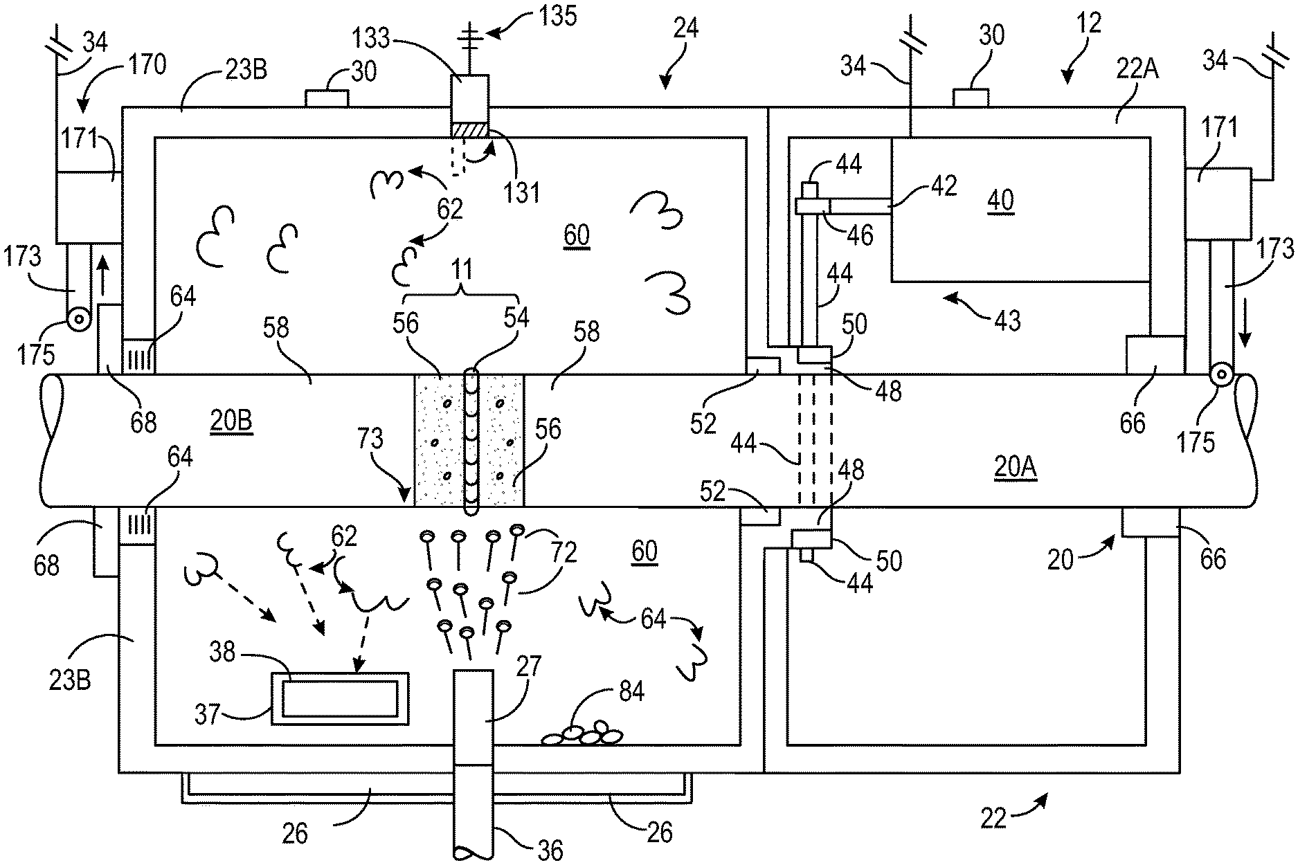
[0060] Referring to all of the figures and specifically to FIG. 2, which presents a representative view of a cross section in the present invention. In addition to the previously introduced elements in discussion regarding FIG. 1, there is illustrated the following elements forming one embodiment of the presently presented invention. Specifically, within the fixed portion 22 and fixed portion wall 22A of the grit blasting containment device 12, there may be a motor 40 coupled to the electric power line 34 with a typical rotor shaft 42 extending therefrom. There may be a first coupling device 46 (which may be a gear) mounted on the rotor shaft 42, and being designed to positively engage a linkage device 44 (which may be a bicycle like chain) that may be positively engaged to a second coupling device 50 (which may be a second gear) that is fixedly mounted to a first portion 48 that may be coupled to the rotating containment portion wall 24A. It is noted that the entire system may be referred to as a linkage system 43 collectively, which would include all of the needed parts (42, 44, 46, 48, 50) to cause the rotation of the rotating containment portion 24.
[0061] In an alternative embodiment regarding the propulsion system 170 discussed previously, there is further illustrated in FIG. 2 an operating unit 171, an extendible linkage unit 173, and a moving carriage unit 175. Wherein, the operating control unit 171 contains mechanical and electrical elements to engage and augment the extending and contracting of the linkage unit 173 toward and away from the pipe 20 in a controlled and directed fashion. The operating control unit 171 may use any known radio, Wi-Fi, blue tooth, direct circuitry, controls and sensors to move the carriage unit 175 into and away from contact with the pipe 20, much like a remote control vehicle, which are well known in the art. The carriage unit 175 may contain any form of wheels and gears or linkages sufficient to enable the operating control unit 171 to enable the carriage unit 175 to extend from a retracted position, to then engage the pipe 20, then to keep extending and thereby pushing against the pipe 20 with sufficient force to lift the grit blasting containment device 12, and the two halves 23A and 23B off of the pipe, much like butter fly wings or a clam shelf opening and closing. Thereafter, the carriage unit 175 could be activated like a remote control vehicle to forcibly move the grit blasting containment device 12 along the pipe 20 to a subsequent position. The following US patents are herein incorporated by reference for their supportive teaching on automated pipeline moving systems and remote control vehicles to illustrate the well known art of moving objects along a pipeline, and other features needed for the functioning of the presently described invention 10, including: U.S. Pat. Nos. 4,092,950, 4,563,841, 5,022,812, 5,337,846, 6,461,231, 5,046,289, 5,136,969 5, 5,205,058, 5,596,319, 5,644,113, 6,030,169, 6,439,956, and U.S. Pat. Nos. 6,746,304, 8,396,611.
[0062] It is noted that the propulsion system 170 illustrated in FIG. 1, shows the two different positions that may be employed. Namely, the left side is retracted away from the pipe 20 and would be the position when the blasting operation is underway, and the right side is in an extended to be in contact with the pipe 20, which is the position requisite for opening the two wall halves 23A and 23B and thus lifting the entire blasting device 12 off of the pipe 20. It is noted that these two left and right side depictions only illustrate the two positions that will simultaneously be undertaken by the right and left sides when engaging in the rotation and lateral movement processes.
[0063] In operation of the rotation of the rotating containment portion 24, and in reference to all of the figures, as the motor 40 is activated, the rotor shaft 42 will rotate accordingly, thereby causing the first coupling device 46 to also rotate, which will engage the linkage device 44 and thereby cause the first portion 48 to rotate since the second coupling device 50 is fixed thereto and coupled to the linkage device 44. Therefore, the entire rotating containment portion 24 will be caused to rotate about and relative to the pipe 20 just as one skilled in the art would easily understand in light of this explanation and the additionally provided disclosure. Also, it is noted that rotational stabilization devices or wheel mechanisms 68 will aid in the smooth rotation 90 of the entire rotating containment portion 24.
[0064] Whereby, it is noted that in the described embodiments, the linkage device 44 would be wrapped completely around the first and second coupling devices if there is a bike-like chain and gearing arrangement to enable the rotation of the first portion 48 and thus the couple rotating containment portion 24. Although, it is noted that there are many other mechanical systems that may enable the desired described rotation thereof. For example, there could be employed a screw-type gear to replace the typical tooth gears 46 and 50, and a rod with matching screw-type teeth system to engage in known fashion. Additionally, there could be a simple belt drive like used on a car cooling fan belt system. Moreover, it is noted that the linkage device 44 could be altogether eliminated in another embodiment that would arrange the rotatable shaft 42 to come into direct contact with the first portion 48 and have the first and second couple devices 46 and 50 positively engaging theretogether. In such an embodiment, the motor 40 may be repositioned in a closer orientation to enable the requisite positive engagement between as commonly known by one skilled in the art of gearing mechanisms
[0065] Additionally, continuing the discussion of elements represented in FIG. 2, there may also be a curtain device 52, in the form of a brush, coupled to the first circular wall portion 48 to separate atmospheric conditions within and between the fixed portion 22 and the rotating containment portion 24. Thus, preventing most air born elements in the rotating containment portion 24 from entering the fixed portion 22. There may also be a releasably fixing device 66, which may be in the form of clamps, designed to temporally and releasably hold the position of the fixed portion 22 relative to the pipe section 22A and thus prevent relative motion therebetween when the motor 40 is activated. It is noted that the fixing device 66 may be in any physical design, form, or arrangement that would allow for the function of securing the fixed positioning of the fixed portion 22 relative to the pipe 20 during the rotational operation of the rotating containment portion 24.
[0066] In another embodiment of the illustrated invention, there are illustrated elements located within and about the rotating containment portion 24 illustrated in both FIGS. 1 and 2. Specifically, there is a containment cavity 60 defined by the containment wall 23. There is illustrated a vacuum hose mounting device 37, designed to releasably mount the vacuum hose 38 through the containment wall 23B. There is illustrated rotational stabilization devices or support device 68, which may be in the form of wheels or a wheel mechanism, that abut to the pipeline 20, that allow for smooth rotation of the rotating containment portion 24 as one skilled in the art would anticipate. Positioned between the containment wall 23B and the pipeline 20 there may be another curtain device 64, like a circular brush, fitted around the periphery of the pipe 20, and designed in any form to prevent dust contamination created within the containment cavity 60 from gaining access to the outside ambient atmosphere where the workers are located.
[0067] Regarding elements shown on the pipeline 20, there are such elements such as a first pipe 20A, and a second pipe 20B, each having a protective covering 58 thereon that does not cover the exposed end section 56 of each pipe 20A and 20B. There is a weld bead 54 that circumvents the entire circumference of the two uncovered pipe end sections 56. These exposed end sections 56 and weld bead 54 forms the work area 11 for the robotic grit blasting device 12.
[0068] In operation, and in reference to all of the figures, the material blasting nozzle portion 27 will project at high speeds a blast material 72 toward the work area 11 and impinge thereon at impact zone 73 as is commonly understood by one skilled in the blasting art. Whereby, the blast material 72 will clean and pit the pipe sections 56 in the work zone 11, thus preparing the pipe for subsequent environmental protection coating process 122 material being much like the pipe coating 58.
[0069] Subsequently, the blast material 72 upon high impact generally will be pulverized into smaller particles and create a dust 62 and larger less pulverized particles 84, which will fill the containment cavity 60. Simultaneously, the grit vacuum device 18 will be activated and suction out the dust particles 62 therethrough the vacuum hose 38 in known vacuum process and operation. Additionally, since the blasting nozzle portion 27 is fixed into the container wall 23B, the entire rotating containment portion 24 will be rotated via the motor 40, linkage device 44, contacting first circular wall portion 48, and other associated parts described therein. Thus, as the motor 40 actuates, the rotating containment portion 24 will rotate completely 360 degrees around the circumference of the pipe work site 11 during the activation of the blasting material 72 impacting the blast zone 73, while the pulverized blasting dust material 62 will be suctioned out of the containment cavity 60 through the vacuum hose 38, and the heavy less pulverized material 84 is collected toward a bottom portion of the cavity 60 in a known fashion. Whereby, upon completion of the entire 360 degrees of rotation the entire system will reverse direction and eventually return to the original starting position of the blasting nozzle 27, and thus the blasting operation is completed. It is noted that during the rotation thereof, the exterior associated hoses and cords 107 will have sufficient excess length to thereby be wrap therearound the rotational containment portion 24 before becoming unwrapped in well understood operation. Also, it is noted that the wheels 68 will assist in the rotation and hold the relative positioning for all associated elements in a known fashion. It is also noted that there are many methods of controlling the rotation herein described, including using stoppers, position sensors, switches, all of which would be obvious to one skilled in the art of rotational movement of mechanical systems.
[0070] Referring now to all the figures and especially referring to FIG. 3, which illustrates an end representative view of the grit blasting containment device 12 that shows previous discussed elements, and additional elements. Specifically, there is a separation, interface, or cut 43 extending down the center of the entire grit blasting containment device 12, and thus has a top cut position starting at the hinge device 30 and extends down to a bottom section located proximate a mounted catch device 26; thus the cut 43 separating the grit blasting containment device 12 into a first half wall 23A and a second half wall 23B. There is also a coupling device 80 designed to hold together the two halves of the robotic grit blasting device 12 and specifically the walls 23A and 23B during operation thereof. Upon closure of the robotic grit blasting device 12, the wheels 68 will come in contact with the pipe 20 and all for friction reduced rotation thereof. Obvious to one skilled in the art, the hinge 30 facilitates the smooth opening and closing of the two half walls 23A and B. Dashed lines 41 illustrate a possible open position of the cut 43, wherein the opening will need to be a sufficient distance to allow for the lifting of the entire grit blasting containment device 12 to be lifted off of the pipe 20 during some moving operations thereof. It is noted that the two half walls 23A and 23B will open in an arcuate motion 83 and be repositioned to an open position 41 of the cut 43. Also, it is noted that as the motor 40 is activated, the associated linkage system 42,44, 46, 50 will cause the entire containment portion 24 to rotate in a rotational direction 90 relative to the pipe 20 and to the fixed portion 22 that is releasably coupled to the pipe 20A via holder 66.
[0071] Also, it is noted that there may be a mounted camera system 133, having radio, internet, Wi-Fi, bluetooth, or other known connection 135, and a rotatable protective cover 131. Wherein, the camera system 135 is positioned to view inside cavity 60 to aid in positioning the grit blasting nozzle 27 in line with the work site 11. The cover 131 may be opened for viewing, and closed during blasting operation via any known remote control method and associated mechanical mechanisms. The following patents are incorporated by reference for their supportive and enabling teaching on how a potential camera embodiment may be implemented with remote viewing capabilities in real time: 2005/0057502, U.S. Pat. Nos. 6,903,724, 8,810,718, 8,994,800, 8,995,945, 9,196,133, 9,237,318, 9,769,368, and U.S. Pat. No. 9,781,565.
[0072] It is additionally noted; the illustrated lifting system of cable 32 and clip 31 is shown in two separate steps. Specifically, the right side shows the clamp 31 being unattached, and the left side shows an attached view where claim 31 is not viewable from that position. Further, it is illustrated that as the cable 32 is lifted or lowered 82 that the cable 32 would exert pressure on attachments 35 and thus cause the two halves 23A and 23B to rotatively open 83 to reach a desired opening position 41 of the divide 43. Thus, enabling the repositioning of the entire blasting system 12 to a subsequent welding site 11.
[0073] In an alternative design, the cable 32, attachments 35, and clamp 31 may or may not be needed in regular operation if moving system 170 is employed and added thereto.
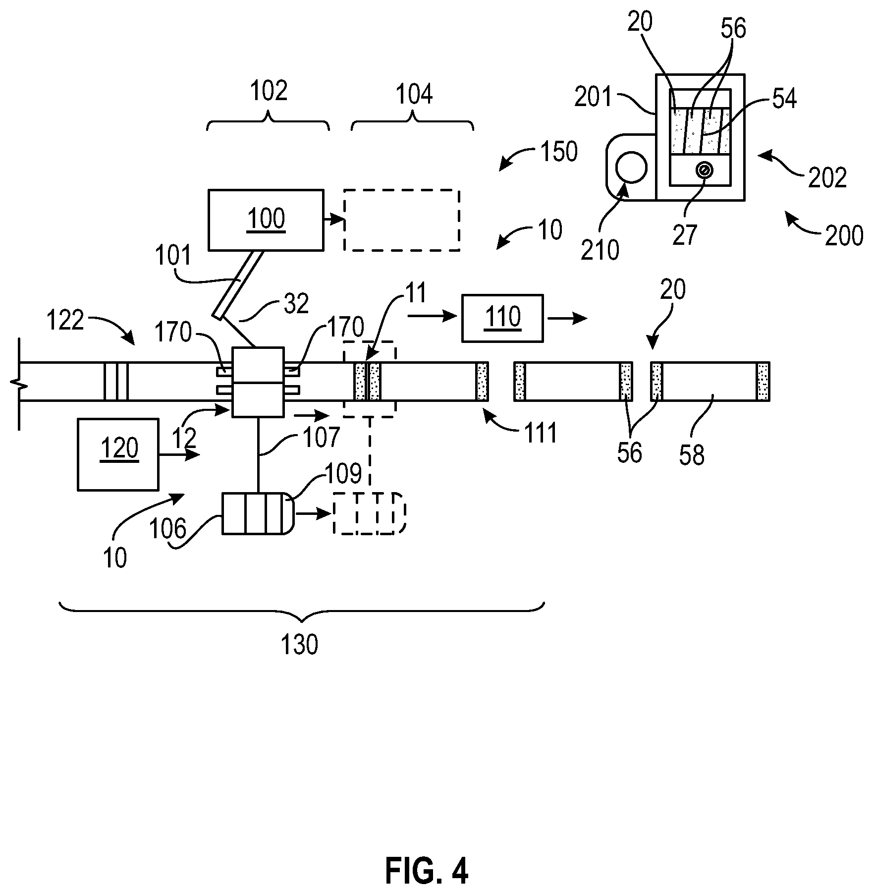
[0074] Referring now to all of the previous figures, and specifically FIG. 4 where there is illustrated a representation of the broad method 150 of implementing the robotic grit blasting system 10. Specifically, in one embodiment, there may be illustrated a pipeline 20 coupling process site 150, which includes the grit blasting containment device 12, the support devices system 106, a pipe welding system 110, a pipe protective coating application system 120, a robotic grit blasting system transporter 100 and its working arm 101. Uniquely, The welding system 110 may include typical pipeline welding operations, including typical workers, welding equipment, all located at a welding site 111 where two unconnected pipe section will be welding together in any known fashion. Moreover, the support devices system 106 in one embodiment may additionally include a vehicle and driver 109. Additionally, the protective coating application system will include known workers and pipeline coating devices, like spray guns, spray material containers, and associated power systems.
[0075] There is also illustrated a remote viewing system 200, having a communication device 201, which may be in the form of a cell phone using any known remote camera monitoring software system. Wherein, the remote viewing system 200 receives real time viewing images using any known data transfer system (blue tooth, Wi-Fi, radio, etc.) from the camera 133 when the protective flap 131 is opened accordingly. Additionally, there is shown a typical viewing screen 202 that will display the camera generated data, which is used by a user to perform accurate positioning of the grit blasting containment device 12 so that the blasting nozzle 27 is properly oriented and lined up and pointing toward the two pipe ends 56 intended to be blasted at the welding site 11. Additionally, there is also illustrated a known remote control device 210 used to communicate and control the operation of the propulsion system 170 by controlling the forward and backward propulsion movement thereof to properly align the grit blasting containment device 12. Again, if the alternative propulsion system 170 is used, the robotic grit blasting system transporter 100, in the form of a vehicle like a truck, will not be needed for each relocation process of the entire system to the subsequent blasting work site 11. The following patents are herein incorporate by reference for their supportive teachings, and illustrating that the remote control and camera technology is well known in the art, regarding remote control system design: U.S. Pat. Nos. 8,568,238, 6,557,041, 7,043,524, 7,633,521, 2019/0297847, 7,218,994, and 2014/0172,197.
[0076] In operations, and in reference to all figures, the entire process site 150 is designed to generally move from a first work site 102 and move to a second work site 104 and continue such along an entire gas pipeline 20 construction project amounting often to dozens and even hundred of miles entailing thousands of weld sites 11. Specifically, pipe 20 is laid out in a linear orientation as shown, and the welding system 110 will weld together two pipe ends 56 theretogether in know fashion and move on to a subsequent un-welded dual pipe interface work site 111. Simultaneously, the welded pipe section 11 will be cleaned by the robotic grit blasting container 12. Where, in moving the blasting device 12, the two halves 23A and 23B are opened in an arcuate direction 83 like a clam shell along hinge 30 and resulting position illustrated by opened position dividing cut 41 and transferred along the pipe to a subsequent work site 11, and after arriving thereat, it will be proper orientated and thereby closed via releasably fixing device 66 and the wall-coupling device 80, removably anchoring the blasting container 12 to the pipe 20 thereat. Thereby, all of the connections 107 may be reattached, if decoupled before hand, to the grit blasting device 12. Thereby, the connector 33 will be uncoupled from holding device 35 that would be mounted to the rotating containment portion 24. Whereby, upon activation of the motor 40 and associated linkages (44, 48 and 50), the robotic grit blasting device 12 is now able to enable the rotating containment portion 24 to rotate completely 360 degrees therearound. Therein, the welded pipe section 11 will be blasted and cleaned by the grit material 72 expelled from grit blasting nozzle 27 in known fashion. Meanwhile, the vacuum system 18, via hose 38, removes the particle dust 62 from the containment cavity 60. After the 360 degree cleaning of the pipe section 11, the rotating containment portion 24 will reverse rotate back into its previous starting position via the motor 40 reversing operation. Thereafter, all of the connections 107 may be disconnected therefrom the robotic grit blasting device 12. Whereby, releasably fixing device 66 and the wall-coupling device 80 will be disengaged, the rod connector 33 will be reinserted into the holding device 35, and the releasable gripper 31 will be reattached thereto as illustrated and the transporter 100 will lift the connected lifting device 32 via arm 101, which will open the two halves of robotic grit blasting device 12 along cut 43 and around hinges 30 in a known fashion a sufficient amount to enable the two halves to clear the diameter of the pipe 20, thus simultaneously allowing heavy materials 84 that were not captured by the vacuum system 18 to fall into the catch tray 26. Thereby, the current work site 102 would be ready to be moved to a subsequent work site 104, where the robotic grit blasting device 12 will be lowered onto the pipe 20 causing the two halves to close around the pipe 20, then recoupling the releasably fixing device 66 to the pipe 20 and enabling the rotational stabilization devices 68 to contact the pipe 20 and the curtain devices 52 and 64 also contact proximate to the pipe 20. Whereby, the wall-coupling device 80 is engaged to releasably hold the two halves of the robotic grit blasting device 12 together while performing the next blasting operation. Finally, the pipe protective coating application system 120 is moved along after the blasting operation is performed, and thus perform coating operations at coating site 122 to protect the remaining exposed and now clean pipe ends 56.
[0077] In the alternative method where the robotic grit blasting system transporter 100 may not be used every step of the subsequent cleaning operations and movement thereof, and may not consistently use the connector 33 and holding device 35; wherein the alternative propulsion system 170 is optionally mounted thereto as illustrated and used in all subsequent operations. Obviously, there will be modifications to the operation thereof in using the alternative propulsion system 170. Specifically, the reconnection and disconnection of the connections 107 may preferably not be required. Additionally, to prep for movement, there would be the added step of engaging the alternative propulsion system 170 to be activated to first extend their carriage device wheels 175 to contact the pipe 20 and thereby force open the two halves of the robotic grit blasting device 12 to position 41. Thereafter, the carriage device 175 may be remotely activated via camera visualization device 200 and moved along the pipe 20 via motion control system 210 until the appropriate position is reached allowing the blasting nozzle 27 be properly positioned for accurate blasting operations. Thereby, the carriage device wheels 175 will be retracted enabling the two halves of the robotic grit blasting device 12 to close around the pipe 20, and are thereby positioned in a retracted non-engaging position as illustrated in FIG. 3. All other previously described operational steps may operate as previously presented.
[0078] It is noted that there are many variation to the presented invention that are well within the scope and understanding of one skilled in the various arts required to design the subject invention. For example, although the description discusses using "grit", this term is a term of art, and is no way limited to "grit" type material. In fact, there are many known materials that are well known, such as glass beads, coal material, sand, etc. Additionally, the linkage engagement portion 43 that is illustrated is only one of hundreds of systems that may enable the motor 40 to couple to the rotating containment portion 24 to rotate 90 during blasting operations.
[0079] It is further noted, the number of illustrated items is merely for illustrative purposes. For example, the there may be more than one blasting nozzles, there may be more than one holding device 66, there may be more than two wheels 68, and etc.
[0080] Also, although the lateral movement system 170 is purely illustrative and not definitive, in that there may only be a single side mounted system on the leading or trailing side relative to the lateral movement discussed in FIG. 4, instead of the illustrated two sided system (one on the leading side and the other on the trailing side). The actual teaching is that most any system will work if it enables the lateral movement of the grit blasting system 12 down the pipeline to subsequent weld sites. There may even be a separate opening system that would widely open the two wall halves 23A and 23B in preparation of the subsequent lateral movement of the entire blasting system 12 to a subsequent weld site 11.
[0081] It should be noted that the steps described in the method of use may be carried out in many different orders according to user preference. The use of "step of" should not be interpreted as "step for", in the claims herein and is not intended to invoke the provisions of 35 U.S.C. .sctn. 112, II 6. Upon reading this specification, it should be appreciated that, under appropriate circumstances, considering such issues as design preference, user preferences, marketing preferences, cost, structural requirements, available materials, technological advances, etc., other methods of use arrangements such as, for example, different orders within above-mentioned list, elimination or addition of certain steps, including or excluding certain maintenance steps, etc., may be sufficient.
[0082] Although specific embodiments have been illustrated and described herein, it will be appreciated by those of ordinary skill in the various arts that any mechanical or electrical arrangement, which is calculated to achieve the same purpose, may be substituted for the specific embodiments shown. This application is intended to cover any adaptations or variations of the present invention. Further, although the invention has been explained in relation to its preferred embodiment, it is to be understood that many other possible modifications and variations can be made without departing from the spirit and scope of the invention.
* * * * *
D00000
D00001
D00002
D00003
D00004
XML
uspto.report is an independent third-party trademark research tool that is not affiliated, endorsed, or sponsored by the United States Patent and Trademark Office (USPTO) or any other governmental organization. The information provided by uspto.report is based on publicly available data at the time of writing and is intended for informational purposes only.
While we strive to provide accurate and up-to-date information, we do not guarantee the accuracy, completeness, reliability, or suitability of the information displayed on this site. The use of this site is at your own risk. Any reliance you place on such information is therefore strictly at your own risk.
All official trademark data, including owner information, should be verified by visiting the official USPTO website at www.uspto.gov. This site is not intended to replace professional legal advice and should not be used as a substitute for consulting with a legal professional who is knowledgeable about trademark law.