Battery Powered Long-Lever Sander
LI; Tingjin
U.S. patent application number 16/236630 was filed with the patent office on 2020-05-14 for battery powered long-lever sander. The applicant listed for this patent is Tingjin LI. Invention is credited to Tingjin LI.
| Application Number | 20200147741 16/236630 |
| Document ID | / |
| Family ID | 68702355 |
| Filed Date | 2020-05-14 |


| United States Patent Application | 20200147741 |
| Kind Code | A1 |
| LI; Tingjin | May 14, 2020 |
Battery Powered Long-Lever Sander
Abstract
The utility model discloses a battery powered long-lever sander. The battery powered long-lever sander includes a sander head assembly and a handle. The sander head assembly is connected to the handle and includes a housing and a sanding disc that is disposed in the housing. The battery powered long-lever sander further includes a driving system connected to the sanding disc and configured to drive the sanding disc to run. The driving system is electrically connected to a driving power source, and the driving power source is a battery pack so that the sander can be used without limitations of plugging of a power wire and thus can be used more conveniently.
| Inventors: | LI; Tingjin; (Zhejiang, CN) | ||||||||||
| Applicant: |
|
||||||||||
|---|---|---|---|---|---|---|---|---|---|---|---|
| Family ID: | 68702355 | ||||||||||
| Appl. No.: | 16/236630 | ||||||||||
| Filed: | December 30, 2018 |
| Current U.S. Class: | 1/1 |
| Current CPC Class: | B24B 47/12 20130101; B24B 7/184 20130101 |
| International Class: | B24B 7/18 20060101 B24B007/18; B24B 47/12 20060101 B24B047/12 |
Foreign Application Data
| Date | Code | Application Number |
|---|---|---|
| Nov 9, 2018 | CN | 201821848640.8 |
Claims
1. A battery powered long-lever sander, characterized by comprising: a sander head assembly that comprises a housing and a sanding disc disposed in the housing; and a driving system connected to the sanding disc and configured to drive the sanding disc to run; wherein the driving system is electrically connected to a driving power source which is a battery pack.
2. The battery powered long-lever sander according to claim 1, characterized in that the battery pack has an output voltage of 18 V to 60 V.
3. The battery powered long-lever sander according to claim 1, characterized in that the driving system comprises a driving motor and a transmission mechanism that is connected in transmission to the sanding disc, wherein the driving motor is a brushless magnet motor or a brush magnet motor; and a control unit of the driving motor is configured to keep a rotating speed constant without consideration of load.
4. The battery powered long-lever sander according to claim 3, characterized in that the brushless magnet motor is a disc type motor/flat type multi-polar high power density motor.
5. The battery powered long-lever sander according to claim 1, characterized by further comprising a handle that is connected to the head assembly.
6. The battery powered long-lever sander according to claim 5, characterized in that the handle comprises a main handle and an extension handle that are connected by means of a quick release assembly.
7. The battery powered long-lever sander according to claim 6, characterized in that a mechanical main power switch is provided on the main handle.
8. The battery powered long-lever sander according to claim 6, characterized in that a power interface of the sander is located on the main handle.
9. The battery powered long-lever sander according to claim 8, characterized in that the power pack is directly connected to the power interface, or connected to the power interface by a wire.
Description
BACKGROUND OF THE INVENTION
[0001] The utility model relates to the technical field of sanders, and more particularly to a battery powered long-lever sander.
[0002] Before plastering, painting or wallpapering of a wall, the wall needs to be sanded and cleaned. As a mature technology, wall sanders have been extensively used. In the prior art, wall sanders are mostly used for sanding a wall, and there may exist some defects as follows when they are used for sanding a ceiling: (1) To facilitate omnidirectional sanding of a ceiling and a wall, a sanding disc and a handle are movably connected to each other. When sanding a ceiling, the sanding disc has only one stressed side with the ceiling, and the load-bearing side comes into contact with the ceiling while the other side of the sanding disc will drop down. When sanding a ceiling, it needs more effort to operate due to uneven stress. (2) An existing sander with a dust suction device may have a poor dust suction effect due to limitations of the mechanism. Secondly, a sanding disc of the wall sander has an abrasive surface structure and is a flat surface as a whole with single structure and function. After being used for a long time, the sanding disc may have a rubbing surface apt to be damaged by the sanding disc and may be difficult to replace. (3) An LED (Light Emitting Diode) strip lamp and a transparent lampshade in a lighting structure of an existing sander are structured separately, and during use, dust still can fall into the transparent lampshade and on the LED strip lamp, affecting the use of the LED strip lamp. (4) Due to an unreasonable design of the dust suction mechanism, the dust suction effect may not be obvious. (5) The handle cannot be extended, resulting in limitations of use. BRIEF SUMMARY OF THE INVENTION
[0003] The utility model aims to provide a battery powered long-lever sander so as to solve the problems of the defects of an existing sander noted in the above background art.
[0004] To achieve the above aim, the utility model provides the following technical solutions:
[0005] A battery powered long-lever sander includes a sander head assembly that includes a housing and a sanding disc disposed in the housing, and also a driving system connected to the sanding disc and configured to drive the sanding disc to run. The driving system is electrically connected to a driving power source which is a battery pack.
[0006] Preferably, the battery pack has an output voltage of 18 V to 60 V.
[0007] Preferably, the driving system includes a driving motor and a transmission mechanism that is connected in transmission to the sanding disc, where the driving motor is a brushless magnet motor or a brush magnet motor; and a control unit of the driving motor is configured to keep a rotating speed constant without consideration of load.
[0008] Preferably, the brushless magnet motor is a disc type motor/flat type multi-polar high power density motor.
[0009] The brushless motor without hall sensor has a driver connected to a main handle, and the main handle includes an aluminum connecting lever through which the driver dissipates heat.
[0010] Preferably, the battery powered long-lever sander further includes a handle that is connected to the sander head assembly. The handle includes a main handle and an extension handle that are connected by means of a quick release assembly.
[0011] Preferably, a mechanical main power switch is provided on the main handle.
[0012] Preferably, a power interface of the sander is located on the main handle.
[0013] Preferably, the power pack is directly connected to the power interface, or connected to the power interface by a wire.
[0014] Preferably, the battery powered long-lever sander further includes a sanding disc suspending device that holds, during sanding, the sanding disc parallel to a wall so that the wall is evenly stressed. The sanding disc suspending device is connected to the housing and the handle and also includes a dust self-suction structure and a lighting device. The dust self-suction structure is arranged within the housing, and the lighting device is connected to the housing.
[0015] Preferably, the dust self-suction structure includes a dust suction fan blade that is connected in transmission to the driving system. The dust suction fan blade is vertically disposed in a dust suction channel. A dust suction hood independent of the housing is arranged outside the dust suction fan blade, and a dust outlet is provided on the dust suction hood, where the dust suction fan blade is collinear, at a part thereof with the strongest suction, with the dust suction channel.
[0016] The dust self-suction structure specifically includes a dust suction inlet provided in the top of the housing. The dust suction hood is connected to the dust suction inlet. The dust suction channel is formed between the dust suction inlet and the dust outlet on the dust suction hood. The dust suction fan blade is arranged in the dust suction hood and connected in transmission to an output shaft of the motor.
[0017] Preferably, the lighting device includes an LED strip lamp and a transparent lampshade that are molded integrally.
[0018] The lighting device may be connected to the outside of the housing in any known manner.
[0019] Specifically, the LED lamp strip includes a substrate and a plurality of series-connected LED leads disposed on the substrate. A transparent encapsulating material is disposed on the outer surfaces of the LED leads. The transparent encapsulating material fills the space between the LED strip lamp and the transparent lampshade so that the LED strip lamp and the transparent lampshade are formed into an integrated structure. The LED strip lamp and the transparent lampshade are hermetically connected by the transparent encapsulating material so that dust can be prevented from entering the transparent lampshade.
[0020] Preferably, the quick release assembly includes a first connecting terminal located at an end of the main handle, a second connecting terminal located at an end of the extension handle, and a connecting component disposed on the first connecting end. The connecting component includes a connecting base vertically connected to the outer surface of the first connecting terminal. A movable locking spanner is connected to the connecting base. The locking spanner includes a locking end at the head and a hand-holding portion connected to the locking end. When connecting, the main handle is nested with the first connecting terminal and the second connecting terminal that are both placed on the extension handle, and then the locking spanner is pulled. When the locking end is perpendicular to the outer surface of the first connecting terminal on the main handle, a lock state is reached. The main handle and the extension handle are connected after the first connecting terminal and the second connecting terminal are held down on each other.
[0021] Specifically, the connecting base includes a connecting portion extending from the outer surface of the first connecting terminal. The connecting portion is provided with a first through hole, while the locking end is provided with a second through hole, and the locking spanner is connected to the connecting base by using a pin shaft passing through the first through hole and the second through hole.
[0022] The sanding disc suspending device includes a mounting base disposed on the housing. A symmetrical supporting arm extends from the tail end of the handle, and the other end of the supporting arm is connected to the mounting base. The sanding disc suspending device further includes at least one strip-like elastic piece, with two ends of the strip-like elastic piece being fixedly connected to the supporting arm. A snap-in device for fixing the strip-like elastic piece is disposed below the strip-like elastic piece. The middle portion of the strip-like elastic piece is fastened in the snap-in device, and the snap-in device is capable of hooking on to the strip-like elastic piece so as to elastically connect one side of the sander head to the supporting arm. In use, when the sanding disc comes into contact with a wall, the stressed side can be pulled down by the strip-like elastic piece so that the sanding disc remains parallel to the wall and the working center of gravity of the sander head is effectively balanced. Thus, when sanding a ceiling, the ceiling may be evenly stressed and less effort may be needed to operate, thereby improving the comfort of an operator.
[0023] Compared with the prior art, the utility model has the following advantages: using a battery pack as the driving power source, the sander can be used without limitations of plugging of a power wire and thus can be used more conveniently. The sanding disc suspending device can hold, during sanding, the sanding disc parallel to a wall so that the wall is evenly stressed. Secondly, the dust suction fan blade of the dust self-suction structure is collinear, at a part thereof with the strongest suction, with the dust suction channel, thereby enhancing the dust suction effect. Next, the handle can be lengthened and shortened with high flexibility. The LED strip lamp and the transparent lampshade of the lighting device are hermetically connected by the transparent encapsulating material so that dust can be prevented from entering the transparent lampshade. The utility model is novel in structure design and highly practicable.
BRIEF DESCRIPTION OF THE DRAWINGS
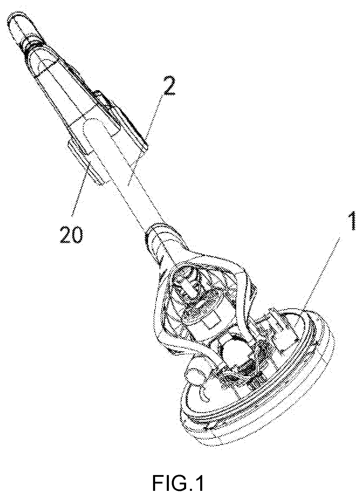
[0024] FIG. 1 is a look-down schematic structure diagram of the utility model.
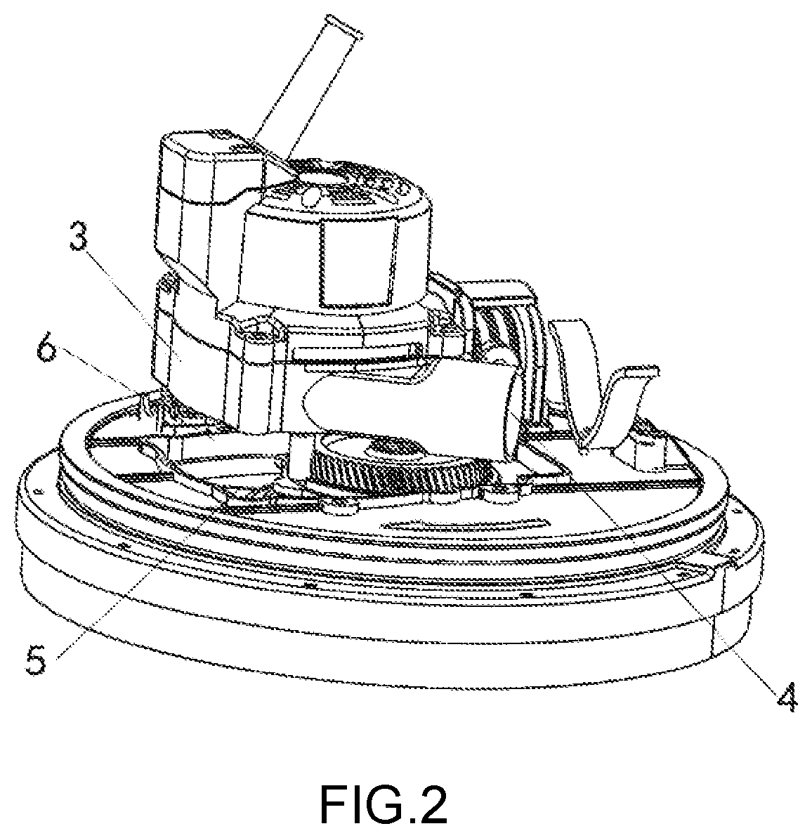
[0025] FIG. 2 is a partial schematic structure diagram of a dust self-suction structure of FIG. 1.
[0026] FIG. 3 is a schematic structure diagram of a quick release assembly of FIG. 1.
[0027] FIG. 4 is a schematic structure diagram of a sanding disc suspending device of FIG. 1.
DETAILED DESCRIPTION OF THE INVENTION
[0028] The technical solutions in embodiments of the utility model will be described clearly and fully in combination with the accompanying drawings in the embodiments of the utility model. It is apparent that the described embodiments are merely part of, rather than all, embodiments of the utility model. Any other embodiments obtained by those of ordinary skill in the art based on the embodiments in the utility model without creative efforts shall fall into the scope of protection of the utility model.
[0029] Referring to FIGS. 1-4, the utility model provides a technical solution as follows:
[0030] A battery powered long-lever sander includes a sander head assembly 1. The sander head assembly 1 includes a housing and a sanding disc disposed in the housing. The battery powered long-lever sander also includes a driving system connected to the sanding disc and configured to drive the sanding disc to run. The driving system is electrically connected to a driving power source which is a battery pack. The battery pack has an output voltage of 18 V to 60 V.
[0031] The driving system includes a driving motor and a transmission mechanism that is connected in transmission to the sanding disc, where the driving motor is a brushless magnet motor or a brush magnet motor; and a control unit of the driving motor is configured to keep a rotating speed constant without consideration of load. The brushless magnet motor is a disc type motor/flat type multi-polar high power density motor. The brushless motor without hall sensor has a driver connected to a main handle, and the main handle includes an aluminum connecting lever through which the driver dissipates heat.
[0032] The battery powered long-lever sander further includes a handle 2 that is connected to the sander head assembly. The handle includes a main handle 7 and an extension handle 8 that are connected by means of a quick release assembly. A mechanical main power switch is provided on the main handle. A power interface of the sander is located on the main handle. The power pack is directly connected to the power interface, or connected to the power interface by a wire.
[0033] The battery powered long-lever sander further includes a sanding disc suspending device that holds, during sanding, the sanding disc parallel to a wall so that the wall is evenly stressed. The sanding disc suspending device is connected to the housing and the handle and also includes a dust self-suction structure and a lighting device. The dust self-suction structure is arranged within the housing and includes a dust suction fan blade (not shown) that is connected in transmission to the driving system. The dust suction fan blade is vertically disposed in a dust suction channel. A dust suction hood 3 independent of the housing is arranged outside the dust suction fan blade, and a dust outlet 4 is provided on the dust suction hood, where the dust suction fan blade is collinear, at a part thereof with the strongest suction, with the dust suction channel. The dust self-suction structure specifically includes a dust suction inlet 5 provided in the top of the housing. The dust suction hood 3 is connected to the dust suction inlet. The dust suction channel 6 is formed between the dust suction inlet and the dust outlet on the dust suction hood. The dust suction fan blade is arranged in the dust suction hood and connected in transmission to an output shaft of the motor. The driving system is electrically connected to a driving power source. The driving power source is a battery pack, and the battery pack is the one with an output voltage of 18 V.
[0034] The quick release assembly includes a first connecting terminal 9 located at an end of the main handle, a second connecting terminal 10 located at an end of the extension handle, and a connecting component 11 disposed on the first connecting end. The connecting component includes a connecting base 12 vertically connected to the outer surface of the first connecting terminal. A movable locking spanner is connected to the connecting base. The locking spanner includes a locking end 14 at the head and a hand-holding portion 15 connected to the locking end. When connecting, the main handle is nested with the first connecting terminal and the second connecting terminal that are both placed on the extension handle, and then the locking spanner is pulled. When the locking end is perpendicular to the outer surface of the first connecting terminal on the main handle, a lock state is reached. The main handle and the extension handle are connected after the first connecting terminal and the second connecting terminal are held down on each other. Specifically, the connecting base includes a connecting portion extending from the outer surface of the first connecting terminal. The connecting portion is provided with a first through hole, while the locking end is provided with a second through hole, and the locking spanner is connected to the connecting base by using a pin shaft passing through the first through hole and the second through hole. The driving system includes a driving motor and a transmission mechanism that is connected in transmission to the sanding disc, where the driving motor is a brushless magnet motor or a brush magnet motor. The transmission mechanism is already described above in detail and will not be redundantly described herein. The driving system is electrically connected to a driving power source. The driving power source is a battery pack that outputs a low-voltage direct current. The driving power source may also be a direct-current power source. The lighting device is connected to the housing. The lighting device includes an LED strip lamp and a transparent lampshade that are molded integrally. The lighting device may be connected to the outside of the housing in any known manner. Specifically, the LED lamp strip includes a substrate and a plurality of series-connected LED leads disposed on the substrate. A transparent encapsulating material is disposed on the outer surfaces of the LED leads. The transparent encapsulating material fills the space between the LED strip lamp and the transparent lampshade so that the LED strip lamp and the transparent lampshade are formed into an integrated structure. The LED strip lamp and the transparent lampshade are hermetically connected by the transparent encapsulating material so that dust can be prevented from entering the transparent lampshade. The lighting device is already described above in detail and will not be redundantly described herein.
[0035] The sanding disc suspending device includes a mounting base 16 disposed on the housing. A symmetrical supporting arm 17 extends from the tail end of the handle, and the other end of the supporting arm is connected to the mounting base 16. The sanding disc suspending device further includes at least one strip-like elastic piece 18, with two ends of the strip-like elastic piece being fixedly connected to the supporting arm. A snap-in device 19 for fixing the strip-like elastic piece is disposed below the strip-like elastic piece. The middle portion of the strip-like elastic piece is fastened in the snap-in device, and the snap-in device is capable of hooking on to the strip-like elastic piece so as to elastically connect one side of the sander head to the supporting arm. In use, when the sanding disc comes into contact with a wall, the stressed side can be pulled down by the strip-like elastic piece so that the sanding disc remains parallel to the wall and the working center of gravity of the sander head is effectively balanced. Thus, when sanding a ceiling, the ceiling may be evenly stressed and less effort may be needed to operate, thereby improving the comfort of an operator.
[0036] While the embodiments of the utility model are already illustrated and described, for those of ordinary skill in the art, it will be understood that various changes, modifications, replacements and variations can be made to such embodiments without departing from the principles and spirit of the utility model. The scope of the utility model is defined by the appended claims and equivalents thereof.
* * * * *
D00000
D00001
D00002
D00003
XML
uspto.report is an independent third-party trademark research tool that is not affiliated, endorsed, or sponsored by the United States Patent and Trademark Office (USPTO) or any other governmental organization. The information provided by uspto.report is based on publicly available data at the time of writing and is intended for informational purposes only.
While we strive to provide accurate and up-to-date information, we do not guarantee the accuracy, completeness, reliability, or suitability of the information displayed on this site. The use of this site is at your own risk. Any reliance you place on such information is therefore strictly at your own risk.
All official trademark data, including owner information, should be verified by visiting the official USPTO website at www.uspto.gov. This site is not intended to replace professional legal advice and should not be used as a substitute for consulting with a legal professional who is knowledgeable about trademark law.