3-d Printer With Manifolds For Gas Exchange
TenHouten; Broc William ; et al.
U.S. patent application number 16/678625 was filed with the patent office on 2020-05-14 for 3-d printer with manifolds for gas exchange. The applicant listed for this patent is DIVERGENT TECHNOLOGIES, INC.. Invention is credited to Eahab Nagi El Naga, Broc William TenHouten.
| Application Number | 20200147690 16/678625 |
| Document ID | / |
| Family ID | 70551580 |
| Filed Date | 2020-05-14 |


View All Diagrams
| United States Patent Application | 20200147690 |
| Kind Code | A1 |
| TenHouten; Broc William ; et al. | May 14, 2020 |
3-D PRINTER WITH MANIFOLDS FOR GAS EXCHANGE
Abstract
Aspects are provided relating to additive manufacturing. In one aspect, an apparatus for producing a three-dimensional (3D) structure is described that includes a build chamber having a top portion with windows through which radiative energy from one or more sources is provided to the build chamber to produce the 3D structure, and one or more manifolds disposed within the build chamber. The manifolds are configured to perform a gas exchange within the build chamber, and each manifold is positioned above a region where envelopes of radiative energy from the one or more sources overlap. In another aspect, the manifolds are moved to a first position adjacent to the top portion of the build chamber during a first mode of operation and moved to a second position away from the top portion of the build chamber during a second mode of operation.
| Inventors: | TenHouten; Broc William; (Los Angeles, CA) ; El Naga; Eahab Nagi; (Los Angeles, CA) | ||||||||||
| Applicant: |
|
||||||||||
|---|---|---|---|---|---|---|---|---|---|---|---|
| Family ID: | 70551580 | ||||||||||
| Appl. No.: | 16/678625 | ||||||||||
| Filed: | November 8, 2019 |
Related U.S. Patent Documents
| Application Number | Filing Date | Patent Number | ||
|---|---|---|---|---|
| 62760305 | Nov 13, 2018 | |||
| Current U.S. Class: | 1/1 |
| Current CPC Class: | B22F 2003/1056 20130101; B29C 64/364 20170801; B22F 3/1055 20130101; B29C 64/153 20170801; B33Y 40/00 20141201; B29C 64/35 20170801; B33Y 10/00 20141201; B33Y 30/00 20141201 |
| International Class: | B22F 3/105 20060101 B22F003/105; B33Y 30/00 20060101 B33Y030/00 |
Claims
1. An apparatus for producing a three-dimensional (3D) structure, comprising: a build chamber; one or more radiative energy sources configured to generate two different envelopes of radiative energy that overlap in an overlap region within the build chamber; and a manifold disposed within the build chamber and proximate to the overlap region, the manifold configured to perform a gas exchange within the build chamber.
2. The apparatus of claim 1, wherein the build chamber includes at least one of: a first gas outlet configured to remove from the build chamber, as part of the gas exchange, contaminated gas, a first gas inlet configured to introduce into the build chamber, as part of the gas exchange, clean gas, or a combination thereof.
3. The apparatus of claim 2, wherein the manifold is further configured to include at least one of: a second gas outlet configured to remove from the build chamber, as part of the gas exchange, the contaminated gas, a second gas inlet configured to introduce into the build chamber, as part of the gas exchange, the clean gas, or a combination thereof.
4. The apparatus of claim 1, wherein the manifold includes an elongated structure vertically positioned above the overlap region and including at least a gas inlet or a gas outlet at one end of the elongated structure that is near a region in the build chamber where the 3D structure is produced.
5. The apparatus of claim 1, further comprising one or more additional manifolds, wherein the manifold and the one or more additional manifolds are separately disposed along a length of the build chamber such that each manifold performs the gas exchange for a different region of the build chamber.
6. The apparatus of claim 1, wherein the build chamber comprises two or more windows through which radiative energy from the one or more radiative energy sources is provided, the apparatus further comprising a number of manifolds that is one fewer than a number of the windows.
7. The apparatus of claim 1, wherein the manifold is disposed at a fixed position within the build chamber.
8. The apparatus of claim 1, wherein the manifold is configured to perform the gas exchange during a mode of operation of the build chamber, the mode of operation being at least a fusing mode or a re-coating mode.
9. The apparatus of claim 1, wherein the manifold is configured to move along a vertical direction, a horizontal direction, a rotational direction, or a combination thereof relative to a top portion of the build chamber.
10. An apparatus for producing a three-dimensional (3D) structure, comprising: a build chamber; one or more radiative energy sources configured to provide radiative energy into the build chamber; and multiple manifolds disposed within the build chamber and configured to perform a gas exchange within the build chamber, wherein the multiple manifolds are positioned adjacent to a top portion of the build chamber during a first mode of operation and positioned away from the top portion of the build chamber during a second mode of operation.
11. The apparatus of claim 10, wherein the multiple manifolds are separately disposed along a length of the build chamber such that any two consecutive manifolds perform the gas exchange for a different region of the build chamber.
12. The apparatus of claim 10, wherein one of fusing or re-coating is performed during the first mode of operation and the gas exchange is performed by the multiple manifolds during the second mode of operation.
13. The apparatus of claim 12, wherein the multiple manifolds are repositioned adjacent to the top portion of the build chamber in the first mode of operation after the gas exchange is performed during the second mode of operation.
14. The apparatus of claim 10, wherein the multiple manifolds perform an additional gas exchange during the first mode of operation that is different from the gas exchange performed during the second mode of operation, the additional gas exchange comprising introducing an amount of clean gas that is larger than an amount of contaminated gas to be removed.
15. The apparatus of claim 10, wherein the one or more radiative energy sources are disposed opposite a powder bed in the build chamber and provide radiative energy into the build chamber during the first mode of operation.
16. The apparatus of claim 15, wherein the top portion of the build chamber includes one or more windows through which the radiative energy from the one or more radiative energy sources is provided, the apparatus further comprising a number of manifolds that is one greater than a number of the one or more windows.
17. The apparatus of claim 16, wherein the multiple manifolds are separately disposed along a length of the build chamber such that each of the one or more windows in the top portion of the build chamber is positioned between two consecutive manifolds.
18. The apparatus of claim 10, wherein a first manifold of the multiple manifolds is disposed at an end of the build chamber and is configured to introduce clean gas, a second manifold of the multiple manifolds is disposed at another end of the build chamber and is configured to remove contaminated gas, and one or more remaining manifolds of the multiple manifolds are separately disposed between the ends of the build chamber and are configured to introduce the clean gas and to remove the contaminated gas.
19. The apparatus of claim 18, wherein the first manifold includes multiple gas inlets to introduce the clean gas, the second manifold includes multiple gas outlets to remove the contaminated gas, and the one or more remaining manifolds include additional gas inlets to introduce the clean gas and additional gas outlets to remove the contaminated gas.
20. An apparatus for producing a three-dimensional (3D) structure, comprising: a build chamber; one or more radiative energy sources configured to generate two different envelopes of radiative energy that overlap in an overlap region within the build chamber; multiple manifolds disposed within the build chamber and configured to perform a gas exchange within the build chamber, wherein the multiple manifolds are positioned adjacent to a top portion of the build chamber during a first mode of operation and positioned away from the top portion of the build chamber and proximate to the overlap region during a second mode of operation.
Description
CROSS-REFERENCE TO RELATED APPLICATION(S)
[0001] This application claims the benefit of U.S. Provisional Application Ser. No. 62/760,305, entitled "3-D PRINTER WITH MANIFOLDS FOR GAS EXCHANGE ENABLING LASER AVOIDANCE AND GRID-LIKE PLENUMS FOR GAS EXCHANGE OVER PRINT AREAS" and filed on Nov. 13, 2018, which is expressly incorporated by reference herein in its entirety.
BACKGROUND OF THE DISCLOSURE
Field
[0002] The present disclosure relates generally to techniques for additive manufacturing (AM), and more specifically to techniques for 3-D printing that include manifolds for gas exchange enabling laser avoidance and grid-like plenums for gas exchange over print areas.
Background
[0003] Additive Manufacturing (AM) processes involve the use of a stored geometrical model for accumulating layered materials on a `build plate` to produce three-dimensional (3-D) objects having features defined by the model. AM techniques are capable of printing complex components using a wide variety of materials. A 3-D object is fabricated based on a computer aided design (CAD) model. The AM process can create a solid three-dimensional object using the CAD model.
[0004] Powder Bed Fusion (PBF) is an AM process that uses a laser to sinter or melt powder deposited in a powder bed, which then bonds the powder particles together in targeted areas to produce a 3-D structure having the desired geometry. Different materials or combinations of material, such as metals, engineering plastics, thermoplastic elastomers, metals, and ceramics may be used in PBF to create the 3-D object. Other more advanced AM techniques, including those discussed further below, are also available or under current development, and each may be applicable to the teachings herein.
[0005] As AM processes continue to improve, manufacturers are increasingly investigating the benefits of using AM components in their designs. Despite recent advances in AM characteristics like build plate size, print speed and precision, and other progressively more sophisticated features of AM-based technology, the use of AM in the various industries has, for the most part, remained limited to producing relatively small-scale components. These limitations include the inability to remove processing byproducts, such as contaminated gases, over large build areas. Thus, the potential for using AM to develop larger and increasingly sophisticated structures remains largely untapped.
SUMMARY
[0006] Several aspects of techniques for gas exchange within an apparatus for producing a 3D structure will be described more fully hereinafter with reference to three-dimensional printing techniques.
[0007] Aspects of an apparatus for producing a 3D structure are described, where the apparatus includes a build chamber, one or more radiative energy sources configured to generate two different envelopes of radiative energy that overlap in an overlap region within the build chamber, and one or more manifolds disposed within the build chamber and proximate to the overlap region. The one or more manifolds are configured to perform a gas exchange within the build chamber.
[0008] Aspects of a method for producing a 3D structure are described, where the method includes enabling one or more manifolds disposed within a build chamber, the build chamber having a top portion with multiple windows through which radiative energy from one or more energy sources is provided to produce the 3D structure, wherein each manifold is positioned above a region where envelopes of radiative energy from the one or more sources overlap, and performing, by the one or more manifolds, a gas exchange within the build chamber.
[0009] Aspects of an apparatus for producing a 3D structure are described, where the apparatus includes a build chamber for producing the 3D structure, one or more radiative energy sources configured to provide radiative energy into the build chamber, and multiple manifolds disposed within the build chamber. The manifolds are configured to perform a gas exchange within the build chamber, and the manifolds are positioned adjacent to a top portion of the build chamber during a first mode of operation and positioned away from the top portion of the build chamber during a second mode of operation.
[0010] Aspects of a method for producing a 3D structure are described, where the method includes enabling a first mode of operation for producing the 3D structure in a build chamber, wherein multiple manifolds are disposed within the build chamber in a first position adjacent a top portion of the build chamber during the first mode of operation, enabling a second mode of operation for producing the 3D structure in the build chamber, moving the manifolds to a second position away from the top portion of the build chamber during the second mode of operation, and performing, by the manifolds while in the second position, a gas exchange within the build chamber.
[0011] Aspects of an apparatus for producing a 3D structure are described, where the apparatus includes a build chamber for producing the 3D structure, one or more radiative energy sources configured to generate two different envelopes of radiative energy that overlap in an overlap region within the build chamber, and multiple manifolds disposed within the build chamber. The manifolds are configured to perform a gas exchange within the build chamber, and the manifolds are positioned adjacent to a top portion of the build chamber during a first mode of operation and positioned away from the top portion of the build chamber and proximate to the overlap region during a second mode of operation.
[0012] It will be understood that other aspects of gas exchange within an additive manufacturing apparatus will become readily apparent to those skilled in the art from the following detailed description, wherein it is shown and described only several embodiments by way of illustration. As will be realized by those skilled in the art, the additively manufacturing transport structures are capable of other and different embodiments and its several details are capable of modification in various other respects, all without departing from the invention. Accordingly, the drawings and detailed description are to be regarded as illustrative in nature and not as restrictive.
BRIEF DESCRIPTION OF THE DRAWINGS
[0013] Various aspects of the methods and apparatuses for gas exchange within an apparatus for producing a 3D structure will now be presented in the detailed description by way of example, and not by way of limitation, in the accompanying drawings, wherein:
[0014] FIGS. 1A-1D illustrate a conceptual side view of an example of a powder bed fusion (PBF) system during different stages of operation.
[0015] FIGS. 2A-2C illustrate various examples of configurations within a PBF system that uses manifolds for gas exchanges that enable laser avoidance in accordance with aspects of this disclosure.
[0016] FIGS. 3A and 3B illustrate examples of manifolds for gas exchanges that enable laser avoidance in accordance with aspects of this disclosure.
[0017] FIG. 4 illustrates a conceptual side view of part of a build chamber with multiple manifolds for gas exchange that enable laser avoidance in accordance with aspects of this disclosure.
[0018] FIG. 5 illustrates a flow diagram of an exemplary method for producing a 3D structure by using manifolds that enable laser avoidance in accordance with aspects of this disclosure.
[0019] FIGS. 6A-6D illustrate conceptual side views of a PBF system operation using grid-like plenums for gas exchange over print areas in accordance with aspects of this disclosure.
[0020] FIG. 7 illustrates a conceptual top view of the PBF system in FIGS. 6A-6D in accordance with aspects of this disclosure.
[0021] FIGS. 8A-8D illustrate different examples of manifolds used in grid-like plenums for gas exchange over print areas in accordance with aspects of this disclosure.
[0022] FIG. 9 illustrates a flow diagram of an exemplary method for producing a 3D structure by using grid-like plenums for gas exchange over print areas in accordance with aspects of this disclosure.
DETAILED DESCRIPTION
[0023] The detailed description set forth below in connection with the appended drawings is intended to provide a description of various exemplary embodiments of additively manufacturing transport structures and is not intended to represent the only embodiments in which the invention may be practiced. The terms "example" and "exemplary" used throughout this disclosure mean "serving as an example, instance, or illustration," and should not necessarily be construed as preferred or advantageous over other embodiments presented in this disclosure. The detailed description includes specific details for the purpose of providing a thorough and complete disclosure that fully conveys the scope of the invention to those skilled in the art. However, the invention may be practiced without these specific details. In some instances, well-known structures and components may be shown in block diagram form, or omitted entirely, in order to avoid obscuring the various concepts presented throughout this disclosure.
[0024] This disclosure is generally directed to additive manufacturing techniques that may be used to produce different types of structures, where large build chambers may be needed and where the removal of processing byproducts such as contaminated gases may take place over large areas. In some instances, these techniques may be used in, for example, the modular assembly of vehicles and other transport structures. In an exemplary aspect of the disclosure, certain components of such transport structures can represent modular components. As shown below, the combination of the additive manufacturing techniques with enhancements to the way in which processing byproducts are removed may provide advantages to the production of different types of large structures. In addition, such techniques can provide distinct advantages to a user. These points are addressed in greater detail below.
[0025] Manufacturers that stand to benefit from this proposed combination of features include, but are not limited to, those that manufacture virtually any mechanized form of transport, which often rely heavily on complex and labor intensive machine tools and molding techniques, and whose products often require the development of complex panels, nodes, and interconnects to be integrated with intricate machinery such as combustion engines, transmissions and increasingly sophisticated electronic techniques. Examples of such transport structures include, among others, trucks, trains, boats, aircraft, tractors, motorcycles, buses, trains, and the like. These transport structures tend to be larger than other types of structures manufactured using additive manufacturing techniques and therefore may require enhanced manufacturing equipment and processing techniques.
[0026] Additive Manufacturing (3-D Printing).
[0027] A variety of different AM techniques have been used to 3-D print components composed of various types of materials. Numerous available techniques exist, and more are being developed. For example, Directed Energy Deposition (DED) AM systems use directed energy sourced from laser or electron beams to melt metal. These systems utilize both powder and wire feeds. The wire feed systems advantageously have higher deposition rates than other prominent AM techniques. Single Pass Jetting (SPJ) is another exemplary technology claimed by its developers to be much quicker than conventional laser-based systems. SPJ combines two powder spreaders and a single print unit to spread metal powder and to print a structure in a single pass with apparently no wasted motion. As another illustration, electron beam additive manufacturing processes use an electron beam to deposit metal via wire feedstock or sintering on a powder bed in a vacuum chamber. Atomic Diffusion Additive Manufacturing (ADAM) is still another recently developed technology in which components are printed, layer-by-layer, using a metal powder in a plastic binder. After printing, plastic binders are removed and the entire part is sintered at once into a desired metal.
[0028] Another AM technique includes PBF. Like DED, PBF creates `build pieces` layer-by-layer. Each layer or `slice` is formed by depositing a layer of powder and exposing portions of the powder to an energy beam. The energy beam is applied to melt areas of the powder layer that coincide with the cross-section of the build piece in the layer. The melted powder cools and fuses to form a slice of the build piece. The process can be repeated to form the next slice of the build piece, and so on. Each layer is deposited on top of the previous layer. The resulting structure is a build piece assembled slice-by-slice from the ground up.
[0029] FIGS. 1A-1D illustrate respective side views of an exemplary PBF system 100 during different stages of operation. The particular embodiment illustrated in FIGS. 1A-1D is one of many suitable examples of a PBF system employing principles of this disclosure. It should also be noted that elements of FIGS. 1A-1D and the other figures in this disclosure are not necessarily drawn to scale, but may be drawn larger or smaller for the purpose of better illustration of concepts described herein.
[0030] PBF system 100 can include a depositor 160 that can deposit each layer of metal powder, a radiative energy source 120 that can generate one or more energy beams, a deflector 130 that can apply the energy beam(s) to fuse the powder, and a build plate 145 that can support one or more build pieces, such as a build piece 140. The PBF system can also include a build floor 150 positioned within a powder bed receptacle. Walls 180a and 180b of a powder bed receptacle generally define the boundaries of the powder bed receptacle, which is sandwiched between the walls from the side and abuts a portion of the build floor 150 below. The build floor 150 can progressively lower build plate 145 (see e.g., FIG. 1B) so that depositor 160 can deposit a next layer. The entire mechanism may reside in a build chamber 110 that can enclose the other components, thereby protecting the equipment, enabling atmospheric and temperature regulation and mitigating contamination risks. In some implementations, radiative energy source 120 and/or deflector 130 can be part of or be included within the build chamber 110. Depositor 160 can include a hopper 165 that contains a powder 175, such as a metal powder, and a leveler 170 that can level the top of each layer of deposited powder.
[0031] Referring specifically to FIG. 1A, this figure shows PBF system 100 after a slice of build piece 140 has been fused, but before the next layer of powder has been deposited. In fact, FIG. 1A illustrates a time at which the PBF system has already deposited and fused slices in multiple layers to form the current state of build piece 140. The multiple layers already deposited have created a powder bed 155, which includes powder that was deposited but not fused.
[0032] FIG. 1B shows PBF system 100 at a stage in which build floor 150 can be lowered by a powder layer thickness 185. The lowering of the build floor causes build piece 140 and powder bed 155 to drop by the same powder layer thickness 185, so that the top of build piece 140 and of powder bed 155 are lower than the top of powder bed receptacle walls 180a and 180b by an amount equal to powder layer thickness 185. In this way, for example, a space with a consistent thickness equal to the powder layer thickness can be created over the tops of build piece 140 and powder bed 155.
[0033] FIG. 1C shows PBF system 100 at a stage in which depositor 160 is positioned to deposit powder 175 in a space created over the top surfaces of build piece 140 and powder bed 155 and bounded by powder bed receptacle walls 180a and 180b. In this example, depositor 160 progressively moves over the defined space while releasing the powder from the hopper 165. Leveler 170 can level the released powder to form a powder layer that has a thickness substantially equal to powder layer thickness 185 (see e.g., FIG. 1B). Thus, the powder in the PBF system can be supported by a powder support structure, which can include, for example, build plate 145, build floor 150, build piece 140, powder bed receptacle walls 180a and 180b, and the like. It should be noted that as illustrated powder layer thickness 185 can be greater than an actual thickness used for the example involving previously-deposited layers discussed above with reference to FIG. 1A. In other words, the powder layer thickness can be different for different layers.
[0034] FIG. 1D shows PBF system 100 at a stage in which, following the deposition of a powder layer having powder layer thickness 185 (FIG. 1C), radiative energy source 120 generates an energy beam 135 and deflector 130 applies the energy beam to fuse the next slice in build piece 140 (e.g., fused powder 157). In various exemplary embodiments, radiative energy source 120 can be an electron beam source, in which case energy beam 135 constitutes an electron beam. The deflector can include deflection plates that can generate an electric field or a magnetic field that selectively deflects the electron beam to cause the electron beam to scan across areas designated to be fused. In various embodiments, radiative energy source 120 can be a laser, in which case energy beam 135 is a laser beam. The deflector can include an optical system that uses reflection and/or refraction to manipulate the laser beam to scan selected areas to be fused. In either case, energy beam 135 may have an associated envelope of radiative energy 190 that represents a potential coverage of the energy beam or a spread of the energy associated with the energy beam.
[0035] In various embodiments, deflector 130 can include one or more gimbals and actuators that can rotate and/or translate radiative energy source 120 to position energy beam 135. In various embodiments, the radiative energy source and/or the deflector can modulate the energy beam, e.g., turn energy beam 135 on and off as the deflector scans so that the energy beam is applied only in the appropriate areas of the powder layer. For example, in various embodiments, the energy beam can be modulated by using signals generated by a digital signal processor (DSP) or other similar signal generating devices or components.
[0036] As mentioned above, despite recent advances in AM characteristics like build plate size, print speed and precision, and other progressively more sophisticated features of AM-based technology, the use of AM in the various industries has, for the most part, remained limited to producing relatively small-scale components. These limitations include the inability to remove processing byproducts, such as contaminated gases, over large build areas. Below are described implementations that use different configurations of manifolds to perform gas exchange over large build areas to remove unwanted byproducts resulting from the fusion of power (e.g., powder 175) when building a next slice in build piece 140.
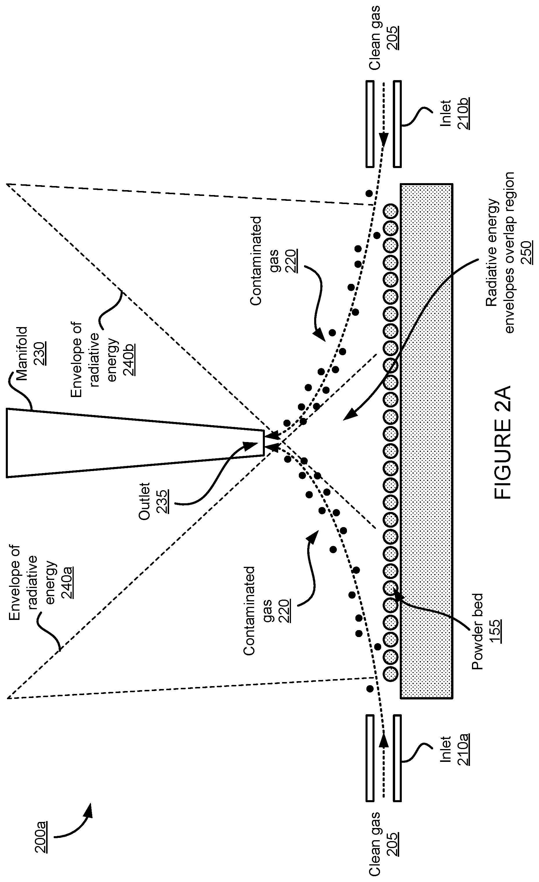
[0037] FIGS. 2A-2C illustrate various examples of configurations within a PBF system (such as PBF system 100) that uses manifolds for gas exchanges that enable laser avoidance in accordance with aspects of this disclosure. In a diagram 200a in FIG. 2A there is shown contaminated gas 220 containing soot that results from the build process inside a build chamber (e.g., build chamber 110 in FIGS. 1A-1D). The contaminated gas that results from a fusing (or fusion) operation is to be removed to avoid having unwanted particles or materials present in the powder that is to be fused in a subsequent fusing operation.
[0038] The example shown in FIG. 2A illustrates a partial side view of a PBF system in which a manifold 230 is positioned between a first envelope of radiative energy 240a associated with a first source (e.g., envelope of an electron beam or laser beam) and a second envelope of radiative energy 240b (e.g., envelope of an electron beam or a laser beam). The manifold is positioned above a region where the two envelopes overlap, which is referred to as a radiative energy envelopes overlap region 250 in the diagram 200a. The positioning of the manifold above the radiative energy envelopes overlap region allows for the fusing of powder in powder bed 155 without interference from the manifold on the areas covered by either first envelope of radiative energy 240a or second envelope of radiative energy 240b. In this way, it is possible to have manifold 230 positioned near powder bed 155 to remove contaminated gas 220 while avoiding the electron or laser beams being used for powder fusion.
[0039] In this example, after a fusing operation that results in contaminated gas 220 remaining near the surface of powder bed 155, clean gas 205 may be provided into build chamber 110 through the sides using inlets 210a and 210b (although more or fewer inlets may be used). The position of each of inlets 210a and 210b is provided by way of illustration and each of the inlets may be placed in a different position than the one shown. The clean gas that enters the build chamber is used to move or push the contaminated gas to an outlet 235 in a bottom portion of manifold 230 and out of build chamber 110. In some implementations, manifold 230 may include multiple outlets 235. The contaminated gas 220 may then be taken to be further processed or disposed.
[0040] Because the diagram 200a in FIG. 2A represents a partial view, the PBF system can include one or more manifolds 230 that operate substantially as described in this example. That is, the PBF system can use one or more manifolds 230 having at least one outlet 235 in the bottom portion.
[0041] The example shown in a diagram 200b in FIG. 2B also illustrates a partial side view of a PBF system in which a manifold 230 is positioned between first envelope of radiative energy 240a associated with a first source (e.g., envelope of an electron beam or laser beam) and second envelope of radiative energy 240b (e.g., envelope of an electron beam or a laser beam). Again, manifold 230 is positioned above the region where the two envelopes overlap (e.g., radiative energy envelopes overlap region 250).
[0042] In this example, after a fusing operation that results in contaminated gas 220 remaining near the surface of powder bed 155, clean gas 205 may be provided into the build chamber 110 through an inlet 210 in the bottom portion of the manifold 230 (although more inlets may be used). The clean gas that enters build chamber 110 is used to move or push contaminated gas 220 to outlets 235a and 235b through a side of build chamber 110. The position of each of outlets 235a and 235b is provided by way of illustration and each of the outlets may be placed in a different position than the one shown. The contaminated gas may then be taken to be further processed or disposed.
[0043] Because diagram 200b in FIG. 2B represents a partial view, the PBF system can include one or more manifolds 230 that operate substantially as described in this example. That is, the PBF system can use one or more manifolds 230 having at least one inlet 210 in the bottom portion.
[0044] In the example shown in a diagram 200c in FIG. 2C, a partial side view of a PBF system is illustrated in which a manifold 230 is positioned between first envelope of radiative energy 240a and second envelope of radiative energy 240b. Again, manifold 230 is positioned above the region where the two envelopes overlap (e.g., radiative energy envelopes overlap region 250).
[0045] In this example, after a fusing operation that results in contaminated gas 220 remaining near the surface of powder bed 155, clean gas 205 may be provided into build chamber 110 through an inlet 210a in the bottom portion of the manifold 230 (although more inlets may be used) and through an inlet 210b on a side of build chamber 110. The clean gas that enters build chamber 110 is used to move or push contaminated gas 220 to outlet 235a through a side of the build chamber 110 and an outlet 235b on the bottom portion of manifold 230. The position of each of inlet 210b and outlet 235a is provided by way of illustration and each of inlet 210b and outlet 235a may be placed in a different position than the one shown. Once out of build chamber 110, contaminated gas 220 may then be taken to be further processed or disposed.
[0046] Because diagram 200c in FIG. 2C represents a partial view, the PBF system can include one or more manifolds 230 that operate substantially as described in this example. That is, the PBF system can use one or more manifolds 230 having at least one inlet 210 and one outlet 235 in the bottom portion.
[0047] The examples described in FIGS. 2A-2C show different configurations of the manifold 230, one where it is used to extract, retrieve, or collect the contaminated gas 220 (FIG. 2A), one where it is used to provide the clean gas 205 (FIG. 2B), and one where it is configured to do both. FIGS. 3A and 3B illustrate more detailed examples of these different manifold configurations. For example, a diagram 300a in FIG. 3A shows a perspective view of manifold 230 having a tapered shape with the upper or top portion being wider than the lower or bottom portion. In this configuration, manifold 230 may be used to extract contaminated gas 220 (FIG. 2A) from the build chamber 110 with one or more outlets (e.g., outlets 235) in the bottom portion or to provide clean gas 205 (FIG. 2B) to build chamber 110 with one or more inlets (e.g., inlets 210) in the bottom portion.
[0048] A diagram 300b in FIG. 3B shows a perspective view of manifold 230 having a similar tapered shape as in FIG. 3A. In this configuration, manifold 230 may be used to both extract contaminated gas 220 (FIG. 2A and FIG. 2C) with one or more outlets (e.g., outlets 235) in the bottom portion and provide clean gas 205 (FIG. 2B and FIG. 2C) with one or more inlets (e.g., inlets 210) in the bottom portion.
[0049] While manifold 230 in the diagrams 300a and 300b is shown with a tapered shape, other shapes may also be used. Moreover, manifold 230 is shown as a single structure, however, it can be implemented as multiple, separate structures, each configured to extract a portion of contaminated gas 220, provide a portion of the clean gas 205, or do both.
[0050] FIG. 4 shows a diagram 400 that illustrates a partial side view of a build chamber with multiple manifolds for gas exchange. For a build chamber to be configured to fabricate larger build pieces (e.g., build piece 140), multiple radiative energy sources (e.g., electron or laser sources) may be used to fuse powder over a much larger build area that can be done with a single source. When multiple sources are used for a large area build operation, multiple manifolds may also be needed to effectively remove the soot generated over such a large area as a byproduct of the build operation. These manifolds need to be placed or positioned in such a way that they do not interfere with the radiative energy (e.g., electron or laser beams) generated by sources and provided into the build chamber to fuse the powder. Therefore, to avoid interfering with the electron or laser beams, the manifolds may be positioned inside the build chamber between envelopes of radiative energy and above where these envelopes overlap, as illustrated in diagram 400.
[0051] In the example shown in diagram 400, build chamber 110 described above in connection with FIGS. 1A-1D can include an upper portion or build chamber top portion, also referred to as a chamber top 410. The chamber top can have more than one window through which radiative energy (e.g., in the form of an electron or laser beam) is provided into build chamber 110 to fuse powder to add to the build piece 140. For example, chamber top 410 can include windows 430a, 430b, and 430c, through which sources 420a, 420b, and 420c can respectively radiate beams (e.g., electron or laser beams) into build chamber 110. Each of sources 420a, 420b, and 420c has a respective envelope that covers a specific area of powder bed 155, and the combination of these areas provides for a large overall area for the fusing operation. For example, radiative energy source 420a has a corresponding envelope of radiative energy 240a that covers approximately a left third of the area of powder bed 155 and can be used to fuse powder over this area. Radiative energy source 420b has a corresponding envelope of radiative energy 240b that covers approximately a middle third of the area of powder bed 155 and can be used to fuse powder over this area. Radiative energy source 420c has a corresponding envelope of radiative energy 240c that covers approximately a right third of the area of powder bed 155 and can be used to fuse powder over this area. Envelope 240a may overlap with envelope 240b in an overlap region 250a (e.g., radiative energy envelopes overlap region 250a) and envelope 240b may overlap with envelope 240c in an overlap region 250b (e.g., radiative energy envelopes overlap region 250b).
[0052] In this example, manifolds 230a and 230b are positioned above overlap regions 250a and 250b, respectively, to avoid interference with the beams associated with envelopes 240a, 240b, and 240c. Manifolds 230a and 230b along with the inlets/outlets 210/235 can be used to remove contaminated gas from the build chamber 110 after a fusing operation.
[0053] While the example in diagram 400 shows three windows and two manifolds as part of the overall architecture of build chamber 110, it is to be understood that this example is provided for illustrative purposes and a greater number of windows and manifolds may be used to increase the effective build area and, consequently, the size of the 3D pieces that can be manufactured or fabricated using build chamber 110.
[0054] In one implementation associated with diagram 400, the manifolds can move in synchronization with the beams provided by one or more of sources 420a, 420b, and 420c to perform localized removal of contaminated gas while the beams perform, for example, a fusing operation. The manifolds may be moved along a vertical direction, one or more horizontal directions, a rotational direction, or a combination thereof as illustrated by the arrows in diagram 400. This movement may be used to synchronize the manifolds with the electron or laser beams from the sources and/or to better control their position to remove contaminated gas and/or to provide clean gas.
[0055] In summary, FIGS. 1A-4 describe various aspects of an apparatus and a method for producing 3D structures or pieces. FIGS. 1A-1D illustrate an example of a PBF system that may also be used to produce 3D structures or pieces. FIGS. 2A-4 illustrate example configurations and further details of those configurations in accordance with the systems and methods described herein. The example configurations and further details of those configurations illustrated in FIGS. 2A-4 may be applied to a PBF system such as the PBF system of FIGS. 1A-1D or other PBF systems. Accordingly, the apparatus can include a build chamber (e.g., build chamber 110) having a top portion (e.g., chamber top 410) with multiple windows (e.g., windows 430a, 430b, and 430c) through which radiative energy from different sources (e.g., sources 420a, 420b, and 420c) is provided to the build chamber to produce the 3D structure. As shown in the diagram 400 in FIG. 4, the one or more manifolds are disposed within the build chamber and are configured to perform a gas exchange within the build chamber (see e.g., FIGS. 2A-2C and FIGS. 3A and 3B). Moreover, each manifold is further configured to be positioned above a region where envelopes of radiative energy from at least two different sources overlap (see e.g., manifolds 230a and 230b in diagram 400 positioned over overlap regions 250a and 250b, respectively). The different sources can be laser sources (or electron beam sources) and the envelopes of radiative energy of the laser sources correspond to envelopes produced by orienting beams (e.g., laser or optical beams) generated by the laser sources.
[0056] In one implementation, the apparatus can include a gas inlet (e.g., gas inlet 210 of the build chamber) configured to introduce into the build chamber, as part of the gas exchange, clean gas (e.g., clean gas 205). In such implementation, each manifold can be further configured include a gas outlet (e.g., gas outlet 235) to remove from the build chamber, as part of the gas exchange, contaminated gas (e.g., contaminated gas 220) containing soot resulting from producing the 3D structure. An example of such implementation is illustrated in connection with the diagram 200a in FIG. 2A.
[0057] In another implementation, the apparatus can include a gas outlet (e.g., gas outlet 235 of the build chamber) configured to remove from the build chamber, as part of the gas exchange, contaminated gas (e.g., contaminated gas 220) containing soot resulting from producing the 3D structure. In such implementation, each manifold can be further configured to include a gas inlet (e.g., gas inlet 210) to introduce into the build chamber, as part of the gas exchange, clean gas (e.g., clean gas 205). An example of such implementation is illustrated in connection with the diagram 200b in FIG. 2B.
[0058] In yet another implementation, the apparatus can include a gas outlet (e.g., gas outlet 235 of the build chamber) configured to remove from the build chamber, as part of the gas exchange, contaminated gas (e.g., contaminated gas 220) containing soot resulting from producing the 3D structure and a gas inlet (e.g., gas inlet 210 of the build chamber) configured to introduce into the build chamber, as part of the gas exchange, clean gas (e.g., clean gas 205). In such implementation, each manifold is further configured to include a gas outlet (e.g., gas outlet 235) configured to remove from the build chamber, as part of the gas exchange, contaminated gas (e.g., contaminated gas 220) and a gas inlet configured to introduce into the build chamber, as part of the gas exchange, clean gas (e.g., clean gas 205). An example of such implementation is illustrated in connection with the diagram 200c in FIG. 2C.
[0059] These implementation need not be limiting and other implementations can be used that combine some of the features of these implementations. For example, in another implementation, different types of manifolds may be used within the same build chamber, where one type of manifold is used to provide clean gas, another type of manifold is used to remove contaminated gas, and yet another type of manifold is used to do both, provide clean gas and remove contaminated gas.
[0060] In another aspect of the apparatus described in connection with FIGS. 2A-4, each manifold can include an elongated structure (e.g., tapered structure) vertically positioned within the build chamber and having at least one gas inlet, at least one gas outlet, or both at one end of the elongated structure that is near a region in the build chamber where the 3D structure is produced (see e.g., FIGS. 2A-2C and FIGS. 3A and 3B).
[0061] The one or more manifolds in the build chamber can include multiple manifolds separately disposed along a length of the build chamber such that each manifold performs the gas exchange for a different region or area of the build chamber. In the example shown in diagram 400 in FIG. 4, the length of the build chamber can in the longitudinal direction from left-to-right or right-to-left in the figure, while the width of the build chamber can be in the transversal direction into or out of the figure. In some instances, the separation between any two consecutive manifolds is the same. There could be other instances, however, where the separation or distance between any two consecutive manifolds along the length of the build chamber can vary or be different and, consequently, the regions or areas in between manifolds can also vary. Moreover, each manifold can be fixed in a predetermined position within the build chamber. There could be other implementations in which the manifolds are configured to be movable and could be moved in one or more directions within the build chamber (e.g., lateral movements in one or more directions (x-y directions), vertical movements (z direction), and/or rotational movements).
[0062] As shown in the diagram 400 in FIG. 4, the apparatus can contain multiple windows (e.g., windows 430a, 430b, and 430c) in a top portion, where a number of the windows in the top portion of the build chamber is N and a number of the manifolds is N-1, with N being a positive integer number greater or equal to 2 (N.gtoreq.2).
[0063] In another aspect of the apparatus, the build chamber is a chamber configured for powder bed fusion (PBF) additive manufacturing processes and includes a powder bed (e.g., powder bed 155), and each manifold includes an elongated structure (e.g., tapered structure) vertically positioned within the build chamber and having at least one gas inlet, at least one gas outlet, or both at one end of the elongated structure that is near the power bed (see e.g., diagram 400 in FIG. 4).
[0064] In yet another aspect of the apparatus, each manifold is configured to perform the gas exchange during a mode of operation of the build chamber, where the mode of operation is one of a fusing mode (e.g., fusing operation) or a re-coating mode or re-coating operation.
[0065] FIG. 5 illustrates a flow diagram of an exemplary method 500 for producing a 3D structure by using manifolds that enable laser avoidance. The method may be performed based on the apparatus described above in connection with FIGS. 2A-4, e.g., as these examples may be applied to a PBF system such as the PBF system illustrated in FIGS. 1A-1D or other PBF systems.
[0066] At block 510, method 500 optionally includes performing a fusing operation (e.g., fusion mode) as part of producing a 3D structure. Additionally or alternatively, a re-coating operation (e.g., re-coating mode) may be performed at block 510.
[0067] At block 520, method 500 includes enabling one or more manifolds (e.g., manifolds 230a and 230b) disposed within the build chamber (e.g., build chamber 110), where the build chamber has a top portion (e.g., chamber top 410) with multiple windows (e.g., windows 430a, 430b, and 430c) through which radiative energy from different locations of energy sources (e.g., sources 420a, 420b, and 420c at different locations) is provided to produce the 3D structure, and where each manifold is configured to be positioned above a region or area where envelopes of radiative energy from at least two different sources overlap (see e.g., manifolds 230a and 230b in diagram 400 positioned over overlap regions 250a and 250b, respectively). To enable the manifolds may involve activating or turning on the operation of the manifolds to perform gas exchange.
[0068] At block 530, method 500 includes performing, by the one or more manifolds, a gas exchange within the build chamber. Performing the gas exchange includes concurrently performing multiple gas exchanges over different regions or areas of the build chamber. At block 535 within block 530, performing the gas exchange includes removing contaminated gas (e.g., contaminated gas 220) containing soot or other fusing or re-coating byproduct that results from producing the 3D structure (e.g., resulting from a fusing or re-coating operation). At block 540 within block 530, performing the gas exchange includes introducing or providing clean gas (e.g., clean gas 205) into the build chamber to move out and replace the contaminated gas. In some instances, performing the gas exchange includes removing, by each manifold contaminated gas and introducing, by each manifold, clean gas.
[0069] In another aspect of method 500, the one or more manifolds include multiple manifolds separately disposed along a length of the build chamber (see e.g., diagram 400 in FIG. 4), and performing the gas exchange includes performing, by each manifold, the gas exchange for a different region or area of the build chamber. As such, another aspect of method 500 includes enabling the one or more manifolds includes enabling multiple manifolds separately disposed or placed along a length of the build chamber such that each manifold performs the gas exchange for a different region or area of the build chamber. Enabling the one or more manifolds can include concurrently enabling multiple manifolds (e.g., more than one) disposed or positioned along the length of the build chamber.
[0070] In another aspect of method 500, when performing a fusing operation as in block 510, the number of envelopes of radiative energy used during the fusing operation can be N, where the number of manifolds performing the gas exchange is then N-1, and where N is a positive integer number greater or equal to 2.
[0071] In yet another aspect of method 500, the build chamber used in the method is a chamber configured for PBF additive manufacturing processes and includes a powder bed (e.g., powder bed 155), method 500 can further include laterally introducing, as part of the gas exchange, clean gas over the powder bed, and vertically removing, as part of the gas exchange and through the one or more manifolds, contaminated gas containing soot and/or other byproducts resulting from producing the 3D structure (see e.g., FIGS. 2A and 2C). In another aspect, method 500 can further include vertically introducing, as part of the gas exchange and through the one or more manifolds, clean gas, and laterally removing, as part of the gas exchange and over the powder bed, contaminated gas containing soot and/or other byproducts resulting from producing the 3D structure (see e.g., FIGS. 2B and 2C).
[0072] In yet another aspect of method 500, enabling the one or more manifolds disposed within the build chamber includes enabling the one or more manifolds to move along a vertical direction, a horizontal direction, a rotational direction, or a combination thereof relative to the top portion of the build chamber. As such, method 500 can include moving the one or more manifolds, individually or collectively, in a vertical direction (z direction), in one or more horizontal directions (x-y directions), and/or in a rotation. These movements can be used to better position the manifolds for gas exchange within the build chamber.
[0073] The configurations or implementations described above provide one approach to use multiple manifolds within a large area build chamber. Other configurations or implementations are described in more detail below in connection with FIGS. 6A-8D, which can also be combined with the features described above for PBF systems such as the PBF system illustrated in FIGS. 1A-1D or other PBF systems.
[0074] FIGS. 6A-6D show various diagrams that illustrate side views of a PBF system (e.g., PBF system 100) operation using grid-like plenums for gas exchange over print areas in accordance with aspects of this disclosure. As used in this disclosure, the term "plenum" may refer to manifolds or similar structures that can be used within a chamber to exchange gas by introducing clean gas and removing contaminated gas. As such, in this disclosure the term "plenum" and the term "manifold" may be used interchangeably to refer to similar structures.
[0075] In a diagram 600a in FIG. 6A, as described above, for a build chamber to be configured to fabricate larger build pieces (e.g., build piece 140), multiple radiative energy sources (e.g., electron or laser sources) may be used to fuse powder over a much larger build area that can be done with a single source. When multiple sources are used for a large area build operation, multiple manifolds may also be needed to effectively remove the soot generated over such a large area as a byproduct of the build operation. These manifolds need to be placed or positioned in such a way that they do not interfere with the radiative energy (e.g., electron or laser beams) generated by sources and provided into the build chamber to fuse the powder. Therefore, to avoid interfering with the electron or laser beams, the manifolds may be moved to different positions within the build chamber at different stages of operation.
[0076] In the example shown in diagram 600a, a build chamber such as build chamber 110 described above in connection with the example PBF system of FIGS. 1A-1D, e.g., as modified as described herein, or other PBF systems can include chamber top 410. The chamber top can have more than one window through which radiative energy (e.g., in the form of an electron or laser beam) is provided into build chamber 110 to fuse powder to add to build piece 140. For example, chamber top 410 can include windows 430a, 430b, and 430c, through which sources at different locations can respectively radiate beams (e.g., electron or laser beams) into build chamber 110. The use of multiple sources radiating through different windows allows for a fusing or re-coating operation to cover a large area over powder bed 155.
[0077] In this example, manifolds 230a, 230b, 230c, and 230d are positioned just below or adjacent to the chamber top 410 in such a way as to not interfere with the windows 430a, 430b, and 430c. For example, manifold 230a is positioned below chamber top 410 and to the left of window 430a, manifold 230b is positioned below chamber top 410 and between windows 430a and 430b, manifold 230c is positioned below chamber top 410 and between windows 430b and 430c, and manifold 230d is positioned below chamber top 410 and to the right of window 430c. Manifolds 230a, 230b, 230c, and 230d can form a grid-like structure and are aligned at the same or similar position below chamber top 410, e.g., a first position 610. When in first position 610, manifolds 230a, 230b, 230c, and 230d can be said to be in a first mode of operation. In this first mode of operation, manifolds 230a, 230b, 230c, and 230d are retracted such as to be out of the way for any fusing or re-coating operation.
[0078] In a diagram 600b in FIG. 6B, manifolds 230a, 230b, 230c, and 230d are moved individually or collectively to another position away from chamber top 410 and closer or adjacent to powder bed 155 to perform a gas exchange, e.g., a second position 620. Manifolds 230a, 230b, 230c, and 230d are substantially aligned at the second position 620 as illustrated in diagram 600b. When in the second position 620, manifolds 230a, 230b, 230c, and 230d can be said to be in a second mode of operation in which gas exchange can be performed.
[0079] In diagram 600c in FIG. 6C, a vertical movement or translation of manifolds 230a, 230b, 230c, and 230d is illustrated. For example, manifolds can be in the first mode of operation along first position 610 adjacent chamber top 410 so as to not interfere with the electron or laser beams used during a fusing or re-coating operation. The manifolds can then be moved down as part of a second mode of operation to second position 620 adjacent to powder bed 155 to perform a gas exchange to remove soot or any other byproducts of the fusing or re-coating operation. Once the gas exchange is completed, the manifolds can then be moved back to first position 610 and into the first mode of operation.
[0080] Explicitly shown in diagram 600c is a positioning mechanism 630 that can provide vertical translation for the manifolds between first position 610 and second position 620 (and even to one or more positions in between). The positioning mechanism can move each manifold individually or all of the manifolds collectively to the appropriate position. The positioning mechanism is itself placed between the windows in chamber top 410 to avoid interfering with a fusing or re-coating operation. In some implementations, there can be a single positioning mechanism to handle the movement of all of the manifolds, while in other implementations there may be multiple positioning mechanisms to handle the movement of all of the manifolds, with one such implementation being the case where there is a dedicated positioning mechanism for each manifold. Additionally or alternatively, positioning mechanism 630 may enable translation in other directions. For example, positioning mechanism 630 may enable the movement of one or more of the manifolds in one or more lateral directions (x-y directions) and/or in a rotation.
[0081] In a diagram 600d in FIG. 6D, there is shown manifolds 230a, 230b, 230c, and 230d in second position 620 during a gas exchange operation. In this example, manifold 230a on the left side of the build chamber may be configured to introduce or provide clean gas (e.g., clean gas 205) to a region or area between the manifold 230a and manifold 230b corresponding to a left third of powder bed 155. In this case, manifold 230b may be configured to remove or extract contaminated gas (e.g., contaminated gas 220) from that region or area.
[0082] Similarly in this example, manifold 230b on the left/middle side of the build chamber may be configured to introduce or provide clean gas (e.g., clean gas 205) to a region or area between manifold 230b and manifold 230c corresponding to a middle third of powder bed 155. As noted above, manifold 230b may remove or extract contaminated gas (e.g., contaminated gas 220) from the left third of powder bed 155.
[0083] Also in this example, manifold 230c on the right/middle side of the build chamber may be configured to introduce or provide clean gas (e.g., clean gas 205) to a region or area between manifold 230c and manifold 230d corresponding to a right third of powder bed 155. The manifold 230c may remove or extract contaminated gas (e.g., contaminated gas 220) from the middle third of powder bed 155.
[0084] Moreover, manifold 230d on the right side of the build chamber may be configured to remove or extract contaminated gas (e.g., contaminated gas 220) from a region or area between manifold 230c and manifold 230d corresponding to a right third of powder bed 155.
[0085] While the examples in the diagrams 600a-600d show three windows and two manifolds as part of the overall architecture of build chamber 110, it is to be understood that this example is provided for illustrative purposes and a greater number of windows and manifolds may be used to increase the effective build area and, consequently, the size of the 3D pieces that can be manufactured or fabricated using a build chamber such as build chamber 110. Moreover, there may be instances in which fewer windows and manifolds may be used in implementations or configurations such as the ones described in connection with diagrams 600a-600d in FIGS. 6A-6D.
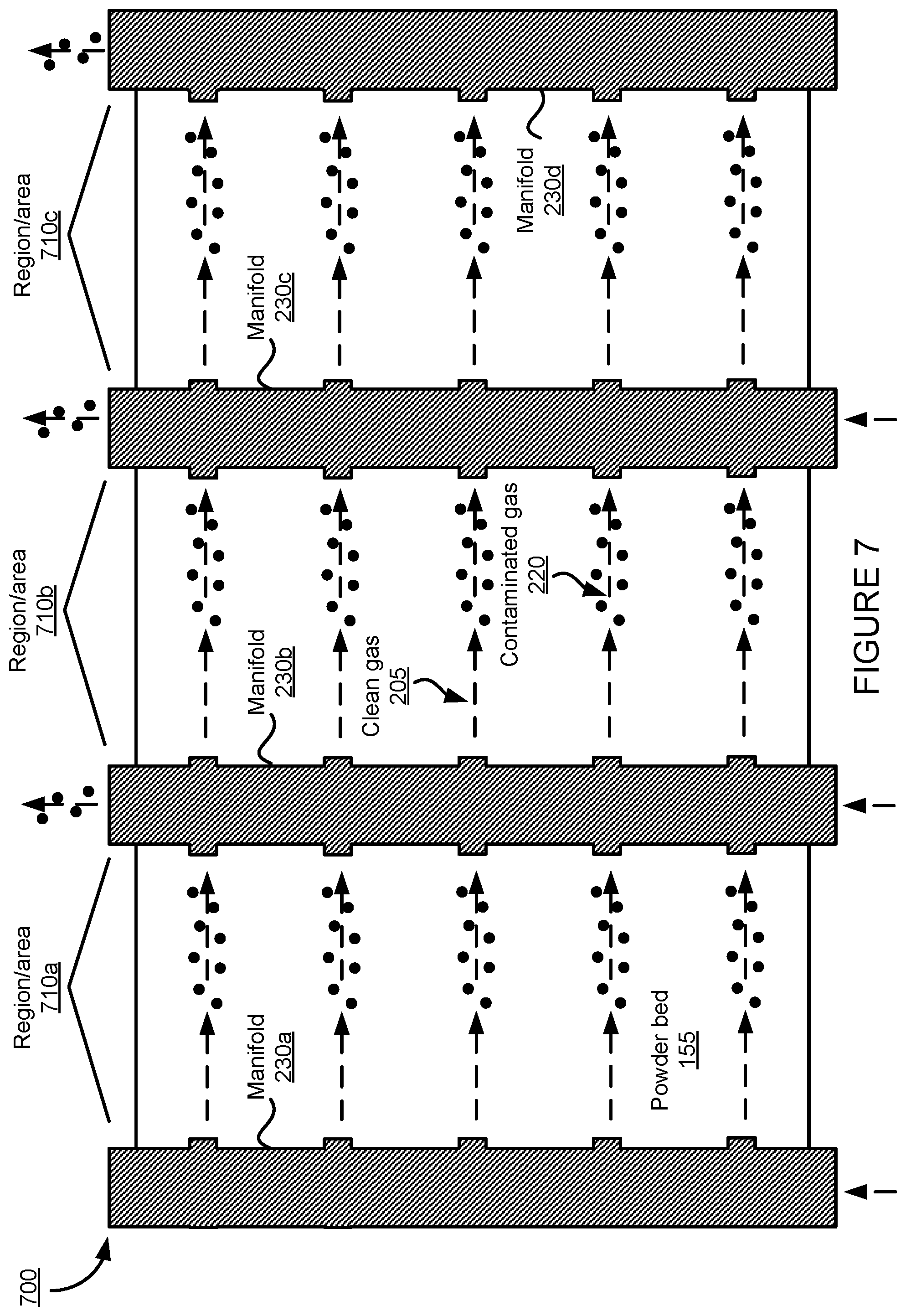
[0086] A diagram 700 in FIG. 7 illustrates a conceptual top view of the PBF system in FIGS. 6A-6D in accordance with aspects of this disclosure. In this example, manifolds 230a, 230b, 230c, and 230d are in second position 620 above or adjacent to powder bed 155 to perform a gas exchange operation. As described above in connection with FIG. 6D, manifold 230a provides clean gas 205 to a region or area 710a that generally covers a left third of powder bed 155 and manifold 230b removes, retrieves, or extracts contaminated gas 220 from the region or area 710a. Similarly, manifold 230b provides clean gas 205 to a region or area 710b that generally covers a middle third of powder bed 155 and manifold 230c removes, retrieves, or extracts contaminated gas 220 from the region or area 710b. Moreover, manifold 230c provides clean gas 205 to a region or area 710c that generally covers a right third of powder bed 155 and manifold 230d removes, retrieves, or extracts contaminated gas 220 from the region or area 710c.
[0087] FIGS. 8A-8D show diagrams 800a, 800b, 800c, and 800d that illustrate different examples of manifolds used in grid-like plenums for gas exchange over print areas as described above in connection with the example PBF system of FIGS. 1A-1D, e.g., as modified as described herein, and FIGS. 6A-7.
[0088] For example, in diagram 800a, a first configuration of a manifold 230 is shown that may be used at one end of the print area (e.g., powder bed 155) to provide clean gas (e.g., clean gas 205) through one or more inlets 210 such as manifold 230a in diagrams 600a-600d and 700. The manifold in this configuration is an elongated structure that can have a circular or elliptical elongated structure (as shown) or can have a different shape (e.g., a square or rectangular elongated structure). The manifold in diagram 800a can have an opening in one end through which the clean gas is provided to manifold 230, while the opposite end of the manifold can be closed. Moreover, although inlets 210 are shown as circular or elliptical inlets more or less evenly spaced, other configurations are also possible where the inlets are of different shapes (e.g., square, rectangular) and/or where the inlets are not evenly or uniformly spaced.
[0089] In diagram 800b, a second configuration of a manifold 230 is shown that may be used at one end of the print area (e.g., powder bed 155) to remove, extract, or retrieve contaminated gas (e.g., contaminated gas 220) through one or more outlets 235 such as manifold 230d in diagrams 600a-600d and 700, for example. The manifold in this configuration is an elongated structure that can have a circular or elliptical elongated structure (as shown) or can have a different shape (e.g., a square or rectangular elongated structure). The manifold in diagram 800b can have an opening in one end through which the contaminated gas is removed from manifold 230, while the opposite end of the manifold can be closed. Moreover, although outlets 235 are shown as circular or elliptical outlets more or less evenly spaced, other configurations are also possible where the outlets are of different shapes (e.g., square, rectangular) and/or where the outlets are not evenly or uniformly spaced.
[0090] In diagrams 800c and 800d, different configurations are shown of manifolds 230 that can introduce clean gas and remove contaminated gas, such as manifolds 230b and 230c shown in diagrams 600a-600d and 700, for example. The configuration described in diagram 800c has the contaminated gas exiting on one end of the manifold and the clean gas being provided on the same end of the manifold. In the configuration described in diagram 800d, the contaminated gas exits on one end of the manifold and the clean gas is provided on an opposite end of the manifold.
[0091] Manifolds 230 in diagrams 800a, 800b, 800c, and 800d can be part of a grid-like structure that includes other manifolds and where the manifolds can be moved in one or more directions either individually (e.g., each separately) or collectively (e.g., all together at the same time).
[0092] In summary, FIGS. 1A-1D (e.g., as modified with one or more features described herein) and FIGS. 6A-8D describe various aspects of another apparatus and another method for producing 3D structures or pieces. Accordingly, the apparatus can include a build chamber (e.g., build chamber 110) within which the 3D structure is produced, and multiple manifolds (e.g., manifolds 230a, 230b, 230c, and 230d as shown in FIGS. 6A-7) disposed within the build chamber. As shown in diagrams 600a-600d and 700 in FIGS. 6A-7, the manifolds are configured to perform a gas exchange within the build chamber. The manifolds are further configured to be moved to a first position (e.g., first position 610) adjacent to a top portion of the build chamber (e.g., chamber top 410) during a first mode of operation and to be moved to a second position (e.g., second position 620) away from the top portion of the build chamber during a second mode of operation (see e.g., FIG. 6C). In one example, the first mode of operation is a fusing mode to perform a first pass of a layer of the 3D structure and the second mode of operation is a re-coating mode to perform a second pass of the layer of the 3D structure.
[0093] In an aspect of this apparatus, the manifolds are separately disposed along a length of the build chamber such that any two consecutive manifolds perform the gas exchange for a different region or area of the build chamber (see e.g., diagram 700 in FIG. 7). Moreover, the manifolds in the apparatus can be separately disposed along a length of the build chamber such that each window in the top portion of the build chamber is positioned between two consecutive manifolds (see e.g., diagram 600a in FIG. 6A).
[0094] The apparatus can include a positioning mechanism (e.g., positioning mechanism 630) configured to move the manifolds to the first position during the first mode of operation and to move the manifolds to the second position during the second mode of operation.
[0095] The apparatus can also include an optical assembly disposed opposite a powder bed (e.g., powder bed 155) in the build chamber and having multiple sources of radiative energy (e.g., one or more radiative energy sources 120 and/or one or more respective deflectors 130 as shown in FIGS. 1A-1D), the radiative energy from at least one of the sources being provided into the build chamber during a build operation to produce the 3D structure. The top portion of the build chamber (e.g., chamber top 410) includes a window for each of the sources, the radiative energy from the at least one of the sources being provided into the build chamber through a corresponding window (see e.g., windows 430a, 430b, and 430c in diagrams 600a-600d in FIGS. 6A-6D). The number of the windows in the top portion of the build chamber is N, and a number of the manifolds is N+1, with N being a positive integer number (e.g., N.gtoreq.1).
[0096] In one implementation of the apparatus, a first of the manifolds is disposed at an end of the build chamber and is configured to introduce clean gas (see e.g., manifold 230a in the diagram 700 in FIG. 7 and manifold 230 in diagram 800a in FIG. 8A), a second of the manifolds is disposed at another end of the build chamber and is configured to remove contaminated gas containing soot resulting from producing the 3D structure (see e.g., manifold 230d in the diagram 700 in FIG. 7 and manifold 230 in diagram 800b in FIG. 8B), and any of the remaining manifolds (middle manifolds) are separately disposed between the ends of the build chamber, and are configured to both introduce clean gas and to remove contaminated gas (see e.g., manifolds 230b and 230c in diagram 700 in FIG. 7 and manifolds 230 in diagrams 800c and 800d in FIGS. 8C and 8D, respectively). In this implementation, the first manifold includes one or more gas inlets, the second manifold includes one or more gas outlets, and the remaining manifolds include one or more gas inlets and one or more gas outlets.
[0097] In another aspect of the other apparatus described above for producing 3D structures or pieces, the build chamber can be a chamber configured for PBF additive manufacturing processes and includes a powder bed (e.g., powder bed 155, and the second position to which the manifolds are moved during the second mode of operation (e.g., second position 620) is closer to the powder bed than to the top portion of the build chamber.
[0098] A flow diagram is shown in FIG. 9 to illustrate an example of a method 900 for producing a 3D structure by using grid-like plenums for gas exchange over different print areas. The method may be performed based on the apparatus described above in connection with FIGS. 1A-1D (e.g., as modified with one or more features described herein) and FIGS. 6A-8D.
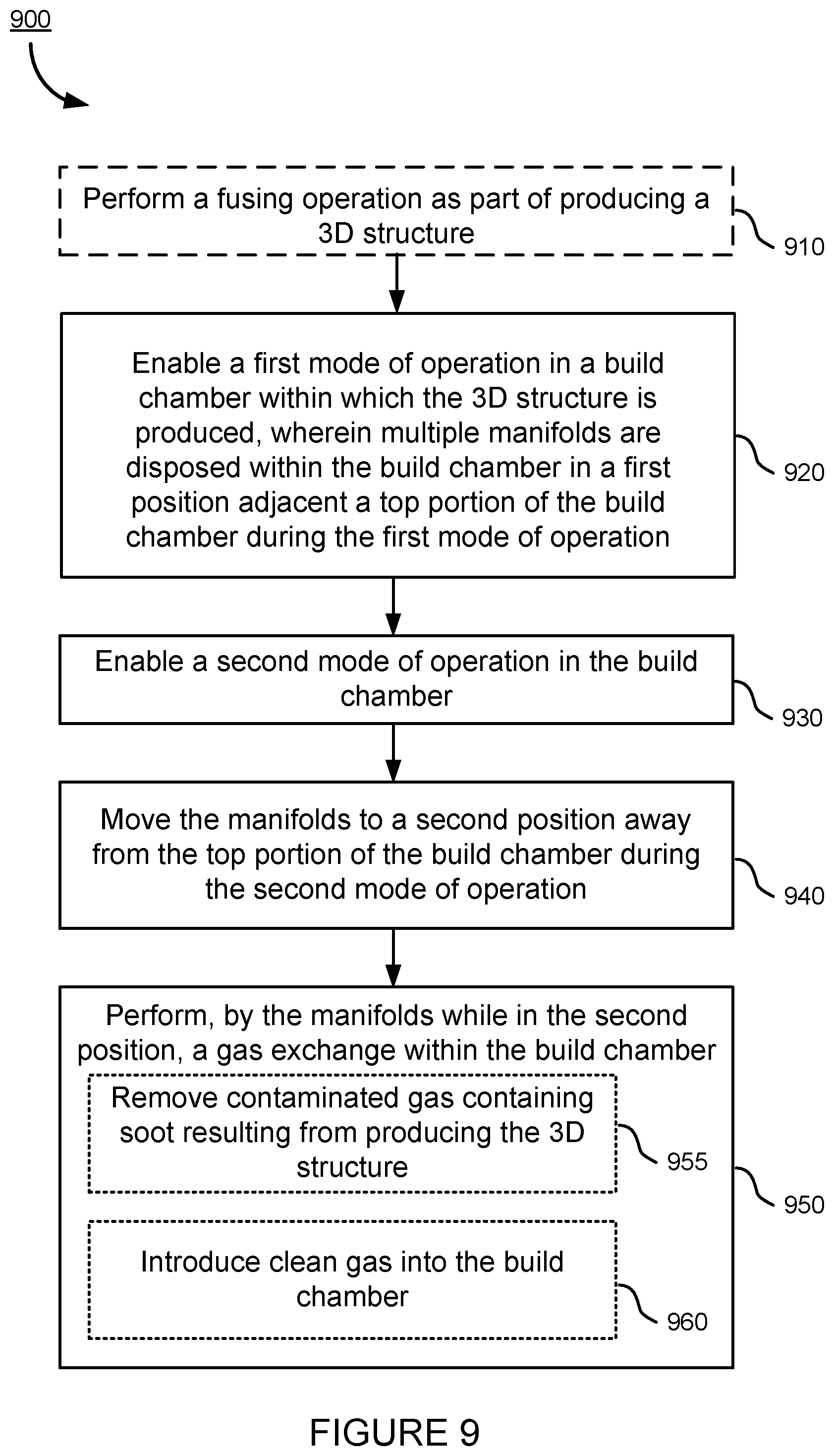
[0099] At block 910, method 900 optionally includes performing a fusing operation (e.g., fusion mode) as part of producing a 3D structure. Additionally or alternatively, a re-coating operation (e.g., re-coating mode) may be performed at block 910.
[0100] At block 920, method 900 includes enabling a first mode of operation in a build chamber (e.g., build chamber 110) within which the 3D structure is produced, wherein multiple manifolds (e.g., manifolds 230a, 230b, 230c, and 230d in the diagram 600a in FIG. 6A) are disposed within the build chamber in a first position (e.g., first position 610) adjacent a top portion of the build chamber (e.g., chamber top 410) during the first mode of operation.
[0101] At block 930, method 900 includes enabling a second mode of operation in the build chamber.
[0102] At block 940, method 900 includes moving the manifolds to a second position (e.g., second position 620) away from the top portion of the build chamber during the second mode of operation (see e.g., diagrams 600b, 600c, and 600d in FIGS. 6B, 6C, and 6D, respectively).
[0103] At block 950, method 900 includes performing, by the manifolds while in the second position, a gas exchange within the build chamber (see e.g., diagram 700 in FIG. 7). At block 955 within block 950, performing the gas exchange includes removing contaminated gas (e.g., contaminated gas 220) containing soot or other fusing or re-coating byproduct that results from producing the 3D structure (e.g., resulting from a fusing or re-coating operation). At block 960 within block 950, performing the gas exchange includes introducing or providing clean gas (e.g., clean gas 205) into the build chamber to move out and replace the contaminated gas.
[0104] In an aspect of method 900, moving the manifolds to the second position includes vertically lowering each of the manifolds to a same distance away from the top portion of the build chamber (see e.g., diagram 600c in FIG. 6C).
[0105] In another aspect of method 900, the method includes enabling the first mode of operation again after the second mode of operation, and moving the manifolds back to the first position once the first mode of operation is again enabled. Moving the manifolds back to the first position may include vertically raising each of the manifolds to be adjacent to the top portion of the build chamber (see e.g., diagram 600c in FIG. 6C).
[0106] In another aspect of method 900, the manifolds can be separately disposed along a length of the build chamber, and performing the gas exchange includes performing, by any two consecutive manifolds, the gas exchange for a different region or area of the build chamber (see e.g., diagram 700 in FIG. 7).
[0107] In yet another aspect of method 900, performing the gas exchange includes concurrently (e.g., at substantially the same time) performing multiple gas exchanges over different regions or areas of the build chamber (see e.g., diagram 700 in FIG. 7). In some implementations, however, there may be temporal offsets between the gas exchanges performed on different regions or areas.
[0108] In another aspect of method 900, the method further includes performing, as part of the first mode of operation, a first pass of a layer of the 3D structure; and performing, as part of the second mode of operation, a second pass of the layer of the 3D structure. In one example, performing the second pass includes performing a re-coating operation.
[0109] In yet another aspect of method 900, the top portion of the build chamber (e.g., chamber top 410) includes multiple windows (e.g., windows 430a, 430b, and 430c in diagram 600a in FIG. 6A) for radiative energy to be provided into the build chamber to produce the 3D structure. The number of the windows can be N, and the number of the manifolds is N+1, with N being a positive integer number (e.g., N.gtoreq.1).
[0110] In another aspect of method 900, the top portion of the build chamber (e.g., chamber top 410) includes multiple windows (e.g., windows 430a, 430b, and 430c in the diagram 600a in FIG. 6A) for radiative energy to be provided into the build chamber to produce the 3D structure, and each of the windows is positioned between two consecutive manifolds (see e.g., diagram 600a in FIG. 6A).
[0111] In yet another aspect of method 900, performing the gas exchange includes introducing clean gas by a first of the manifolds disposed at an end of the build chamber (e.g., manifold 230a in the diagram 700 in FIG. 7), removing contaminated gas containing soot resulting from producing the 3D structure by a second of the manifolds disposed at another end of the build chamber (e.g., manifold 230d in diagram 700 in FIG. 7), and introducing clean gas and removing contaminated gas by any of the remaining manifolds disposed between the ends of the build chamber (e.g., manifolds 230b and 230c in diagram 700 in FIG. 7).
[0112] In another aspect of method 900, the build chamber is a chamber configured for PBF additive manufacturing processes and includes a powder bed (e.g., powder bed 155), and moving the manifolds to a second position includes moving the manifolds closer to the powder bed than to the top portion of the build chamber (see e.g., diagram 600b in FIG. 6B).
[0113] In another aspect of method 900, enabling the first mode of operation includes performing a gas exchange by the manifolds while in the first position (e.g., first position 610) that is different from the gas exchange performed by the manifolds while in the second position (e.g., second position 620), and the gas exchange by the manifolds while in the first position including creating a down pressure within the build chamber by introducing an amount of clean gas that is larger than an amount being removed of contaminated gas containing soot resulting from producing the 3D structure. That is, there can be a gas exchange performed not only when the manifolds are in the second position but additionally or alternatively when the manifolds are in the first position.
[0114] The techniques described above to enhance the way in which additively manufactured parts can be made enables manufacturers to generate shapes, configurations, and structures that are not available in conventional manufacturing processes. Further, advances in AM technologies are expected to continue. Print speed is continually increasing. 3-D printer form factor has also seen regular advances. This means, among other things, that the area of the build platform as compared with the size of the component to be printed is becoming progressively larger as relevant as build plates and printer profiles cross unprecedented boundaries in size, speed and sophistication. The availability and suitability of candidate materials and chemical compounds for use in AM is likewise increasing, meaning among other things that the versatility of AM should continue to impact other applications and other parts of the transport structures.
[0115] In one aspect of the techniques described in this disclosure, complete structures can be additively manufactured, including transport structures such as automobile parts. However, using substantially similar principles as outlined in this disclosure, practitioners skilled in the art will recognize that analogous techniques and identical principles can apply with equal force to numerous classes of transport structures--planes, trains, busses, boats, snowmobiles, motorcycles, and aircraft to name only a few.
[0116] The present disclosure addresses key obstacles and provides solutions for a various shortcomings in the art. The modular design may present easier reparability options for the consumer. As build plates and printer profiles evolve to match or exceed the size of such transports, the manufacturer has the option to decide to maintain modularity of the frame. In some embodiments, the frame can be printed in a single rendering with built in indentations or connections to maintain modularity.
[0117] The previous description is provided to enable any person skilled in the art to practice the various aspects described herein. Various modifications to these exemplary embodiments presented throughout this disclosure will be readily apparent to those skilled in the art, and the concepts disclosed herein may be applied to other techniques for printing nodes and interconnects. Thus, the claims are not intended to be limited to the exemplary embodiments presented throughout the disclosure, but are to be accorded the full scope consistent with the language claims. All structural and functional equivalents to the elements of the exemplary embodiments described throughout this disclosure that are known or later come to be known to those of ordinary skill in the art are intended to be encompassed by the claims. Moreover, nothing disclosed herein is intended to be dedicated to the public regardless of whether such disclosure is explicitly recited in the claims. No claim element is to be construed under the provisions of 35 U.S.C. .sctn. 112(f), or analogous law in applicable jurisdictions, unless the element is expressly recited using the phrase "means for" or, in the case of a method claim, the element is recited using the phrase "step for."
* * * * *
D00000
D00001
D00002
D00003
D00004
D00005
D00006
D00007
D00008
D00009
D00010
D00011
D00012

D00013

D00014

D00015
D00016

D00017

D00018
XML
uspto.report is an independent third-party trademark research tool that is not affiliated, endorsed, or sponsored by the United States Patent and Trademark Office (USPTO) or any other governmental organization. The information provided by uspto.report is based on publicly available data at the time of writing and is intended for informational purposes only.
While we strive to provide accurate and up-to-date information, we do not guarantee the accuracy, completeness, reliability, or suitability of the information displayed on this site. The use of this site is at your own risk. Any reliance you place on such information is therefore strictly at your own risk.
All official trademark data, including owner information, should be verified by visiting the official USPTO website at www.uspto.gov. This site is not intended to replace professional legal advice and should not be used as a substitute for consulting with a legal professional who is knowledgeable about trademark law.