Casting And Method For Manufacturing Casting
YANAGA; Hiroki ; et al.
U.S. patent application number 16/473496 was filed with the patent office on 2020-05-14 for casting and method for manufacturing casting. The applicant listed for this patent is TOYO KOHAN CO., LTD.. Invention is credited to Hiroshi INAZAWA, Toshikazu OOGE, Hirofumi TASHIRO, Hiroki YANAGA.
| Application Number | 20200147681 16/473496 |
| Document ID | / |
| Family ID | 62709488 |
| Filed Date | 2020-05-14 |


View All Diagrams
| United States Patent Application | 20200147681 |
| Kind Code | A1 |
| YANAGA; Hiroki ; et al. | May 14, 2020 |
CASTING AND METHOD FOR MANUFACTURING CASTING
Abstract
The present invention provides a Ni--B--Si three-element-based cast material containing a eutectic part of a solid phase mainly composed of Ni and B and a solid phase mainly composed of Ni and Si, wherein when a straight line is drawn in a surface or a cross section of the eutectic part, the average number of interfaces formed between the solid phase mainly composed of Ni and B and the solid phase mainly composed of Ni and Si on the straight line is at least 2.0 /.mu.m. The present invention also provides a cast material comprising: hard phase particles mainly composed of a boride; and a binder phase containing an alloy containing Ni, Si, and B, wherein the average particle size of the hard phase particles is 3 .mu.m or less, the average aspect ratio is 2.0 or less, the contact ratio is 35% or less, and an intensity ratio I.sub.A/I.sub.B is 1/10 or less, where I.sub.A is the intensity of a peak derived from Ni.sub.31Si.sub.12 observed at a diffraction angle 2.theta. within the range of 46.8.degree. to 47.8.degree., and I.sub.B is the intensity of a peak derived from Ni.sub.3Si observed at a diffraction angle 2.theta. within the range of from 44.0.degree. to 45.0.degree., the intensities being determined by X-ray diffraction measurement using CuK.alpha. radiation.
| Inventors: | YANAGA; Hiroki; (Yamaguchi, JP) ; TASHIRO; Hirofumi; (Yamaguchi, JP) ; INAZAWA; Hiroshi; (Yamaguchi, JP) ; OOGE; Toshikazu; (Yamaguchi, JP) | ||||||||||
| Applicant: |
|
||||||||||
|---|---|---|---|---|---|---|---|---|---|---|---|
| Family ID: | 62709488 | ||||||||||
| Appl. No.: | 16/473496 | ||||||||||
| Filed: | December 26, 2017 | ||||||||||
| PCT Filed: | December 26, 2017 | ||||||||||
| PCT NO: | PCT/JP2017/046582 | ||||||||||
| 371 Date: | June 25, 2019 |
| Current U.S. Class: | 1/1 |
| Current CPC Class: | C22F 1/00 20130101; B22D 27/04 20130101; C22C 1/1036 20130101; C22C 1/045 20130101; C22C 1/02 20130101; C22C 32/0073 20130101 |
| International Class: | B22D 27/04 20060101 B22D027/04; C22C 32/00 20060101 C22C032/00 |
Foreign Application Data
| Date | Code | Application Number |
|---|---|---|
| Dec 27, 2016 | JP | 2016-254171 |
| Dec 27, 2016 | JP | 2016-254179 |
Claims
1. A Ni--B--Si three-element-based cast material containing a eutectic part comprising a solid phase mainly composed of Ni and B and a solid phase mainly composed of Ni and Si, wherein when a straight line is drawn in a surface or a cross section of the eutectic part, the average number of interfaces formed between the solid phase mainly composed of Ni and B and the solid phase mainly composed of Ni and Si on the straight line is 2.0 /.mu.m or more.
2. The cast material according to claim 1, wherein when two perpendicular straight lines are drawn in the surface or the cross section of the eutectic part, the average of the number of interfaces on one of the two straight lines and the number of interfaces on the other straight line is 2.0 /.mu.m or more.
3. A method for manufacturing the cast material according to claim 1, comprising steps of: melting a raw material for forming the cast material, thereby providing a raw material melt; and cooling the raw material melt, wherein the step of cooling the raw material melt comprises continuously cooling the raw material melt at a cooling rate of 100.degree. C./min or more over the temperature range of a cooling start temperature to 400.degree. C.
4. The method for manufacturing the cast material according to claim 3, wherein the raw material melt is cooled by pouring the raw material melt into a mold having a temperature of room temperature to 1100.degree. C.
5. A cast material comprising: hard phase particles mainly composed of a boride; and a binder phase containing an alloy containing Ni, Si, and B, wherein the average particle size of the hard phase particles is 3 .mu.m or less, the average aspect ratio of the hard phase particles is 2.0 or less, the contact ratio between the hard phase particles is 35% or less, the binder phase contains Ni3Si and Ni3B, and the cast material has an intensity ratio I.sub.A/I.sub.B of 1/10 or less, where I.sub.A is the intensity of a peak derived from Ni31 Si12 observed at a diffraction angle 2.theta. within the range of 46.8.degree. to 47.8.degree., and I.sub.B is the intensity of a peak derived from Ni3Si observed at a diffraction angle 2.theta. within the range of from 44.0.degree. to 45.0.degree., the intensities being determined by X-ray diffraction measurement using CuK.alpha. radiation.
6. The cast material according to claim 5, wherein the intensity ratio I.sub.A/I.sub.B is 1/100 or less.
7. The cast material according to claim 5, wherein the hard phase particles comprises at least one of multiple borides represented by Mo2NiB2 and Mo2(Ni,Cr)B2.
8. The cast material according to claim 5, wherein the content of B in the cast material is 1 to 6% by weight.
9. A method for manufacturing a cast material comprising hard phase particles mainly composed of a boride and a binder phase containing an alloy containing Ni, Si, and B, the method comprising: melting mixed raw materials for forming the cast material, thereby providing a melt mixture; continuously cooling the melt mixture at a cooling rate of 100.degree. C./min or more over the temperature range of the cooling start temperature to 400.degree. C., thereby providing a sintered body; and subjecting the sintered body to a heat treatment at a temperature of 700.degree. C. to 950.degree. C.
10. The method for manufacturing a cast material according to claim 9, wherein the raw material melt is cooled by pouring the raw material melt into a mold having a temperature of room temperature to 1100.degree. C.
Description
TECHNICAL FIELD
[0001] The present invention relates to a cast material and a method for manufacturing a cast material.
BACKGROUND ART
[0002] The severity of requirements for wear resistant materials for use in various types of mechanical equipment and mechanical devices has been increasing every year. In recent years, there is a demand for wear resistant materials that have excellent properties such as excellent corrosion resistance and excellent heat resistance as well as high wear resistance.
[0003] As such wear resistant materials, cermet materials, which are composite materials composed of ceramic and metal materials, have been studied so far. Such cermet materials are known to be producible by, for example, a powder metallurgy process that includes: mixing a raw material powder; and firing the raw material powder at a temperature not higher than the melting point thereof while molding (e.g., press-molding) the raw material powder.
[0004] The powder metallurgy process can prevent excessive grain growth of the raw material because the raw material is not melted. As a result, it is possible to prevent the generation of shrinkage cavities and dendrite structures (columnar crystals). The powder metallurgy process, however, may leave voids in resulting cermet materials, and therefore may result in an insufficient density.
[0005] In contrast, Patent Document 1 discloses a method for manufacturing a cast material comprising a cermet containing Mo (molybdenum), Ni (nickel), B (boron), and the like.
PRIOR ART DOCUMENT
Patent Document
[0006] [Patent Document 1] WO 2012/063879
SUMMARY OF INVENTION
Problems to be Solved by Invention
[0007] Unfortunately, although cast materials of cermets manufactured by the casting method disclosed in Patent Document 1 have an increased density, dendrite structures tend to grow inside the cast materials. Therefore, such cast materials manufactured by the casting method disclosed in Patent Document 1 may readily break from those dendrite structures grown therein. For this reason, it has been difficult to use cast materials manufactured by the casting method disclosed in Patent Document 1, in particular, in applications where high bending strength is essential.
[0008] The objective of the present invention is to provide a cast material having excellent corrosion resistance and excellent wear resistance and having high hardness and high bending strength.
Means for Solving Problems
[0009] The present inventors have found that the objective can be achieved by a Ni--B--Si three-element-based cast material containing a eutectic part comprising a solid phase mainly composed of Ni and B and a solid phase mainly composed of Ni and Si, wherein the average number of interfaces formed between the solid phase mainly composed of Ni and B and the solid phase mainly composed of Ni and Si in a surface or a cross section of the eutectic part is controlled within a predetermined range. The present invention has thus been completed.
[0010] Specifically, the present invention provides a Ni--B--Si three-element-based cast material containing a eutectic part comprising a solid phase mainly composed of Ni and B and a solid phase mainly composed of Ni and Si, wherein when a straight line is drawn in a surface or a cross section of the eutectic part, the average number of interfaces formed between the solid phase mainly composed of Ni and B and the solid phase mainly composed of Ni and Si on the straight line is 2.0 /.mu.m or more.
[0011] In the cast material of the present invention, when two perpendicular straight lines are drawn in the surface or the cross section of the eutectic part, the average of the number of interfaces on one of the two straight lines and the number of interfaces on the other straight line is preferably 2.0 /.mu.m or more.
[0012] The present invention further provides a method for manufacturing the cast material, the method comprising the steps of: melting a raw material for forming the cast material, thereby providing a raw material melt; and cooling the raw material melt, wherein the step of cooling the raw material melt comprises continuously cooling the raw material melt at a cooling rate of 100.degree. C./min or more over the temperature range of the cooling start temperature to 400.degree. C.
[0013] In the manufacturing method of the present invention, the raw material melt is preferably cooled by pouring the raw material melt into a mold having a temperature of room temperature to 1100.degree. C.
[0014] The present inventors have further found that the objective can also be achieved by a cast material comprising hard phase particles mainly composed of a boride and a binder phase containing an alloy containing Ni, Si, and B, wherein the average particle size of the hard phase particles, the average aspect ratio of the hard phase particles, and the contact ratio between the hard phase particles are controlled within predetermined ranges, the binder phase contains Ni.sub.3Si and Ni.sub.3B, and a proportion of a peak derived from Ni.sub.3Si in the binder phase determined by X-ray diffraction measurement is controlled within a predetermined range. The present invention has thus been completed.
[0015] Specifically, the present invention provides a cast material comprising hard phase particles mainly composed of a boride and a binder phase containing an alloy containing Ni, Si, and B, wherein the average particle size of the hard phase particles is 3 .mu.m or less, the average aspect ratio of the hard phase particles is 2.0 or less, the contact ratio between the hard phase particles is 35% or less, the binder phase contains Ni.sub.3Si and Ni.sub.3B, and the cast material has an intensity ratio I.sub.A/I.sub.B of 1/10 or less, where I.sub.A is the intensity of a peak derived from Ni.sub.31Si.sub.12 observed at a diffraction angle 2.theta. within the range of 46.8.degree. to 47.8.degree., and I.sub.B is the intensity of a peak derived from Ni.sub.3Si observed at a diffraction angle 2.theta. within the range of from 44.0.degree. to 45.0.degree., the intensities being determined by X-ray diffraction measurement using CuK.alpha. radiation.
[0016] In the cast material of the present invention, the intensity ratio I.sub.A/I.sub.B is preferably 1/100 or less.
[0017] In the cast material of the present invention, the hard phase particles preferably comprise at least one of multiple borides represented by Mo.sub.2NiB.sub.2 and Mo.sub.2(Ni,Cr)B.sub.2.
[0018] In the cast material of the present invention, the content of B in the cast material is preferably 1 to 6% by weight.
[0019] The present invention further provides a method for manufacturing a cast material comprising hard phase particles mainly composite of a boride and a binder phase containing an alloy containing Ni, Si, and B, the method comprising the steps of: melting a mixed raw material for forming the cast material, thereby providing a melt mixture; continuously cooling the melt mixture at a cooling rate of 100.degree. C./min or more over the temperature range of the cooling start temperature to 400.degree. C., thereby providing a sintered body; and subjecting the sintered body to a heat treatment at a temperature of 700.degree. C. to 950.degree. C.
[0020] In the manufacturing method of the present invention, the melt mixture is preferably cooled by pouring the melt mixture into a mold having a temperature of room temperature to 1100.degree. C.
Effect of Invention
[0021] The present invention can provide a cast material having excellent corrosion resistance and excellent wear resistance and having high hardness and high bending strength.
BRIEF DESCRIPTION OF DRAWINGS
[0022] FIG. 1 shows secondary electron image photographs captured after Ar etching of a cross section of the cast material of Example 1 using a field emission Auger microprobe (Auger).
[0023] FIG. 2 is a view for illustrating how to determine the average number of interfaces in the eutectic part.
[0024] FIG. 3 shows secondary electron image photographs captured after Ar etching of a cross section of the cast material of Example 2 using the field emission Auger microprobe (Auger).
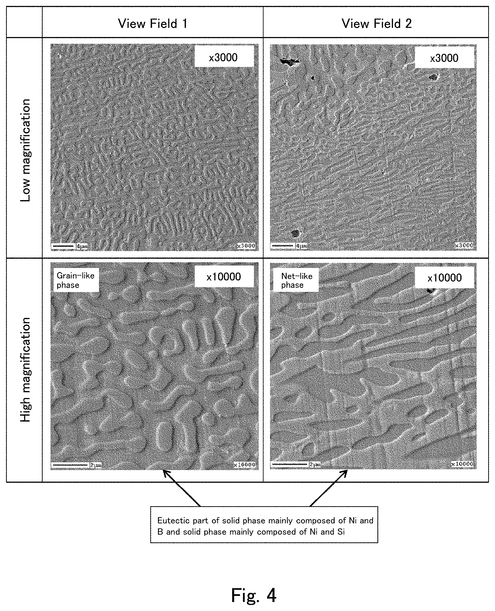
[0025] FIG. 4 shows secondary electron image photographs captured after Ar etching of a cross section of the cast material of Comparative Example 1 using the field emission Auger microprobe (Auger).
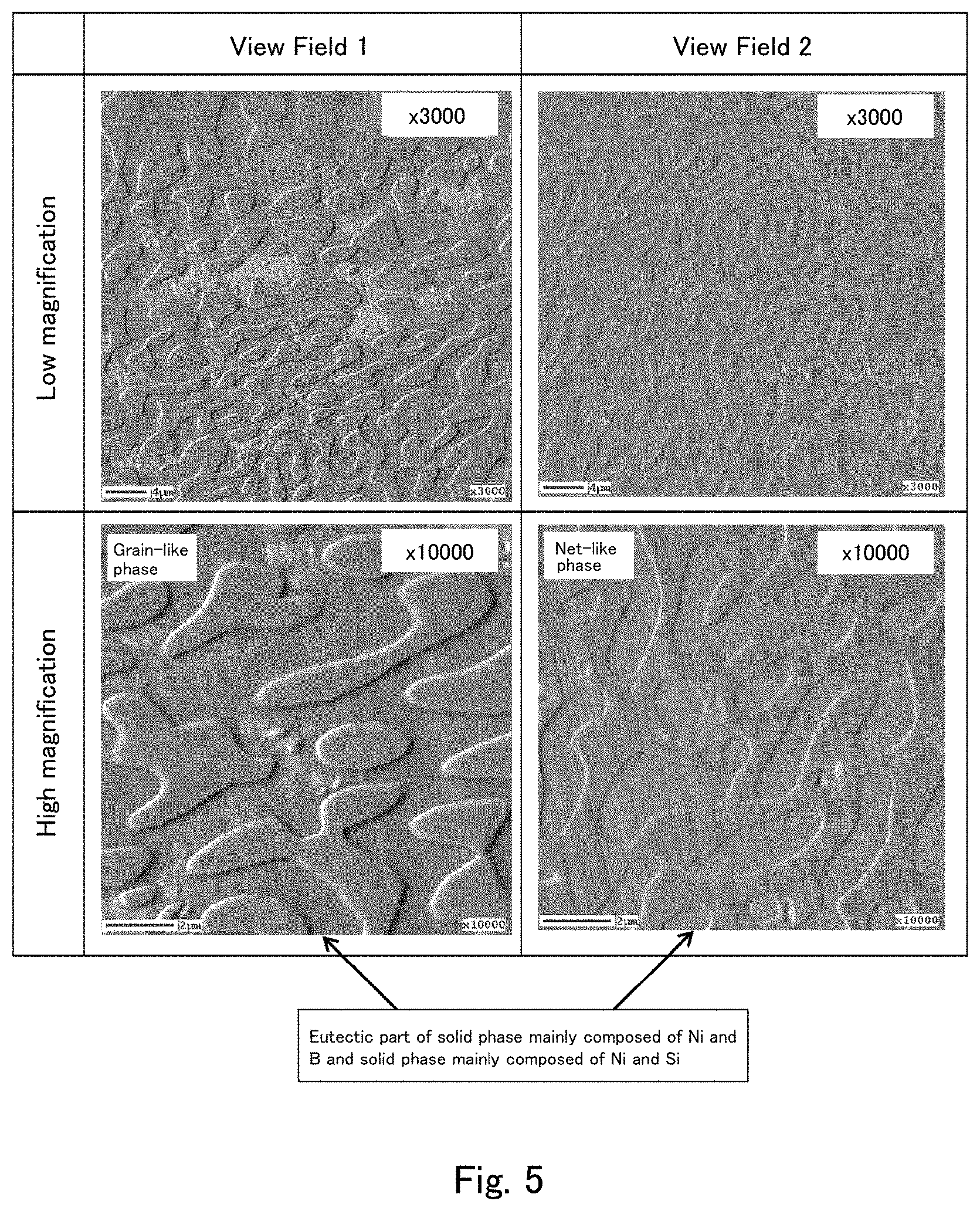
[0026] FIG. 5 shows secondary electron image photographs captured after Ar etching of a cross section of the cast material of Comparative Example 2 using the field emission Auger microprobe (Auger).
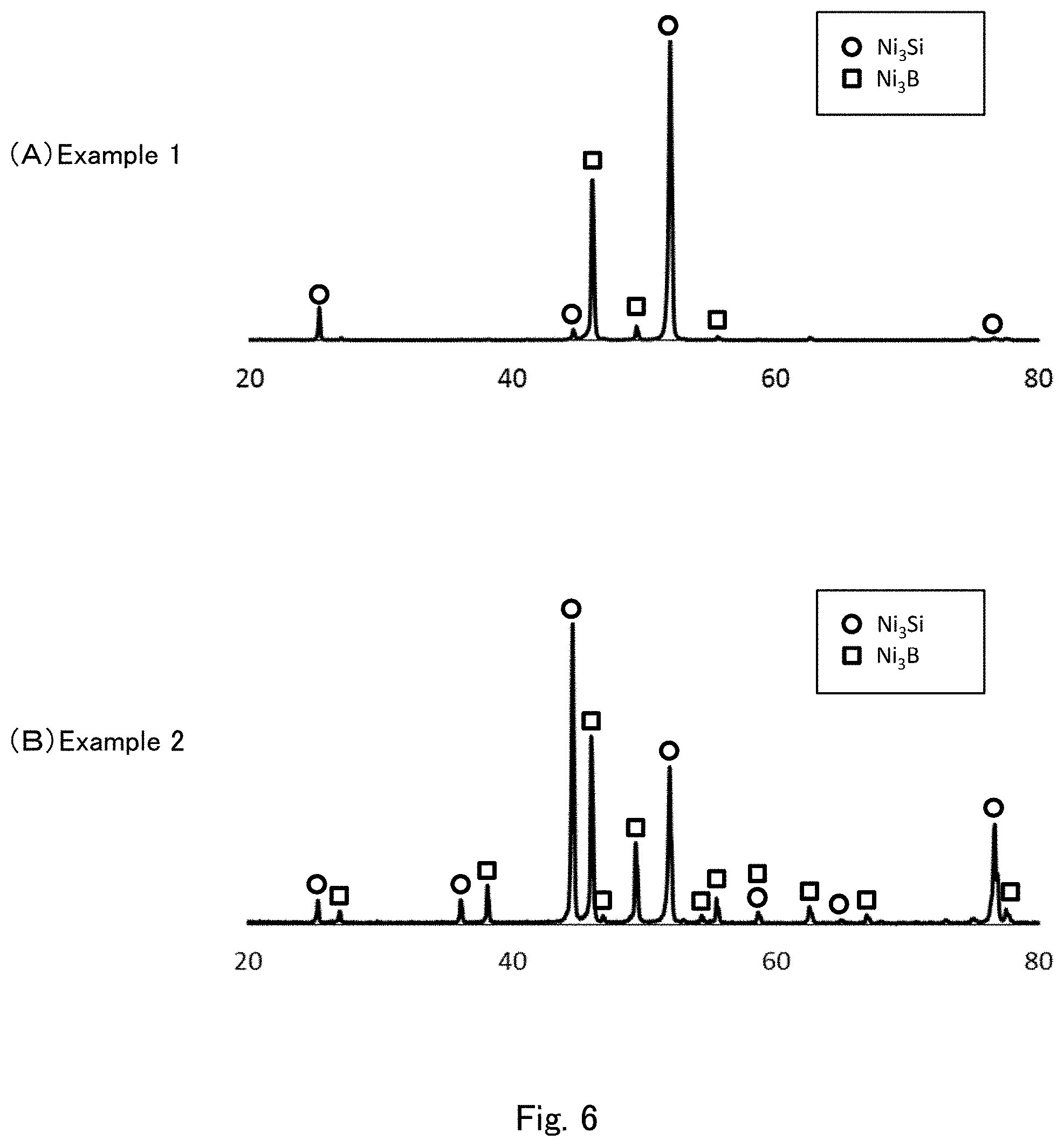
[0027] FIG. 6 shows diffraction pattern graphs obtained by X-ray diffraction measurement of the cast materials of Examples 1 and 2 using CuK.alpha. radiation.
[0028] FIG. 7 shows diffraction pattern graphs obtained by X-ray diffraction measurement of the cast materials of Comparative Examples 1 and 2 using CuK.alpha. radiation.
[0029] FIG. 8 is a view for illustrating how to evaluate the corrosion resistance of a cast material.
[0030] FIG. 9 is a view for illustrating how to measure a microstructure of the cast material of the second embodiment.
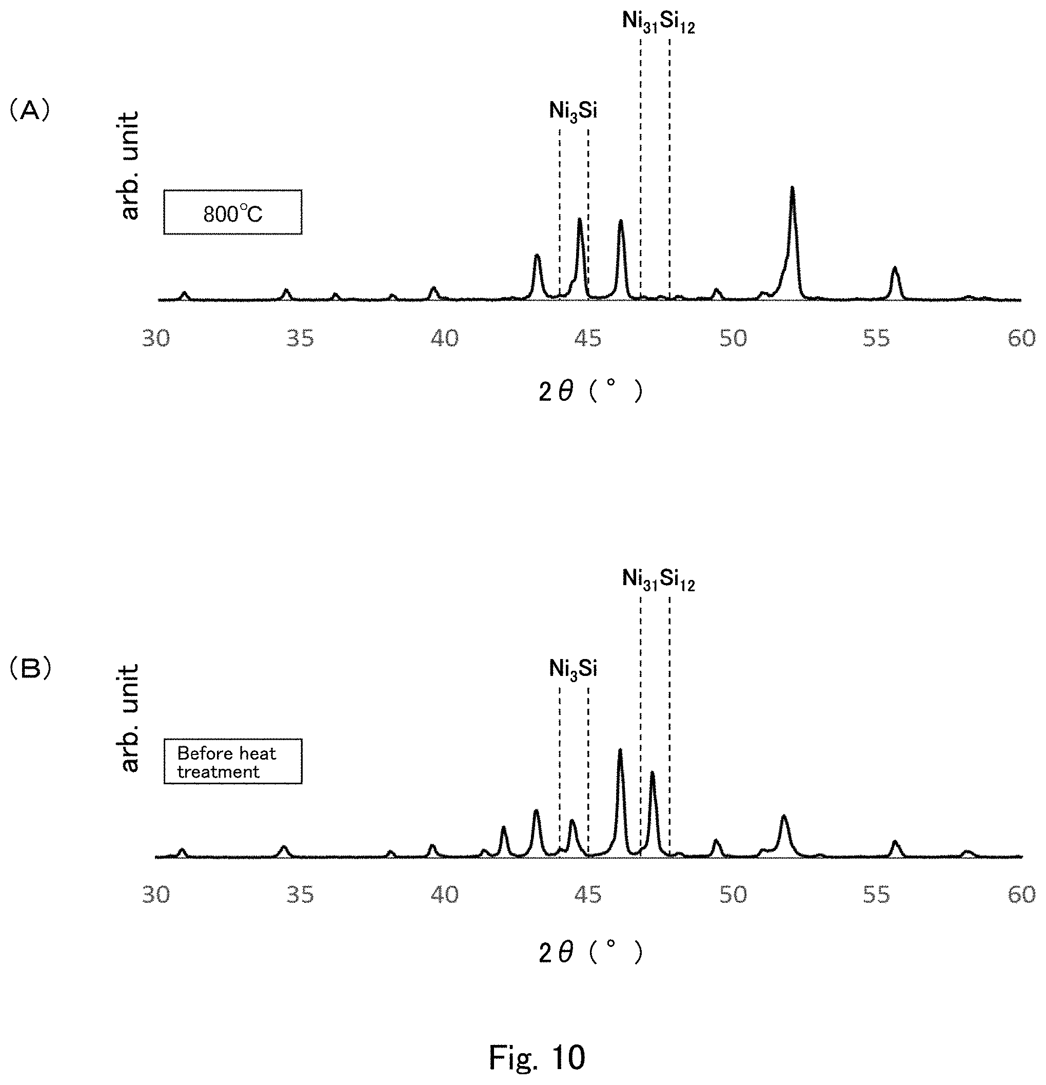
[0031] FIG. 10 shows graphs each showing one exemplary diffraction pattern obtained by X-ray diffraction measurement of the cast material of the second embodiment using CuK.alpha. radiation.
[0032] FIG. 11 shows views for illustrating how to measure the contact ratio between the hard phase particles.
[0033] FIG. 12 shows graphs showing diffraction patterns obtained by X-ray diffraction measurement of cast materials of examples and comparative examples using CuK.alpha. radiation.
[0034] FIG. 13 are secondary electron image photographs captured after Ar etching of cross sections of the cast materials of examples and a comparative example using the field emission Auger microprobe (Auger).
[0035] FIG. 14 shows reflection electron image photographs of cross sections of the cast materials of examples and comparative examples captured using a scanning electron microscope (SEM).
MODE(S) FOR CARRYING OUT THE INVENTION
First Embodiment
[0036] Hereinafter, a cast material of the first embodiment is described.
[0037] The cast material of the present embodiment is a Ni--B--Si three-element-based cast material which contains a eutectic part comprising a solid phase mainly composed of Ni and B and a solid phase mainly composed of Ni and Si, and is characterized in that when a straight line is drawn in a surface or a cross section of the eutectic part, the average number of interfaces formed between the solid phase mainly composed of Ni and B and the solid phase mainly composed of Ni and Si on the straight line is 2.0 /.mu.m or more. When only one straight line is drawn in the surface or the cross section of the eutectic part, the term "average number of interfaces" means the number of interfaces per unit length (.mu.m) of the straight line; when a plurality of straight lines is drawn in the surface or the cross section of the eutectic part, the average number of interfaces means the average of the numbers of interfaces per unit length (.mu.m) determined for the straight lines.
[0038] The cast material of the present embodiment contains a eutectic part containing Ni, Si, and B, more specifically, a eutectic part comprising a solid phase mainly composed of Ni and B and a solid phase mainly composed of Ni and Si. The solid phase mainly composed of Ni and B is mainly composed of Ni.sub.3B, and may partially or entirely contain a Ni solid solution (a solid solution of Ni and at least one element of B and Si). The solid phase mainly composed of Ni and Si is mainly composed of Ni.sub.3Si, and may partially or entirely contain a Ni solid solution (a solid solution of Ni and at least one element of B and Si). The composition of the solid phase mainly composed of Ni and B and that of the solid phase mainly composed of Ni and Si can be determined by X-ray diffraction measurement of the cast material. The eutectic part of the cast material of the present embodiment remarkably improves the hardness and the bending strength of the cast material, and the cast material has remarkably improved corrosion resistance compared to other cast materials such as those mainly composed of an Fe-based alloy.
[0039] The cast material of the present embodiment can be obtained, for example, by melting a raw material powder and the like for forming the cast material to prepare a raw material melt, and then cooling the raw material melt under predetermined conditions in the manner described below. The obtained cast material may be further subjected to a heat treatment, if necessary.
[0040] When a straight line is drawn in a surface or a cross section of the eutectic part of the cast material of the present embodiment, the average number of interfaces formed between the solid phase mainly composed of Ni and B (hereinafter, also referred to as "NiB phase") and the solid phase mainly composed of Ni and Si (hereinafter, also referred to as "NiSi phase") is 2.0 /.mu.m or more, preferably 2.5 /.mu.m or more, more preferably 3.0 /.mu.m or more. When the average number of interfaces is within the above range, crystals constituting the eutectic part have smaller particle sizes, which contributes to a remarkable improvement in bending strength of the resulting cast material. The upper limit of the average number of interfaces is not particularly limited, but is preferably 6.0 /.mu.m or less, more preferably 5.0 /.mu.m or less.
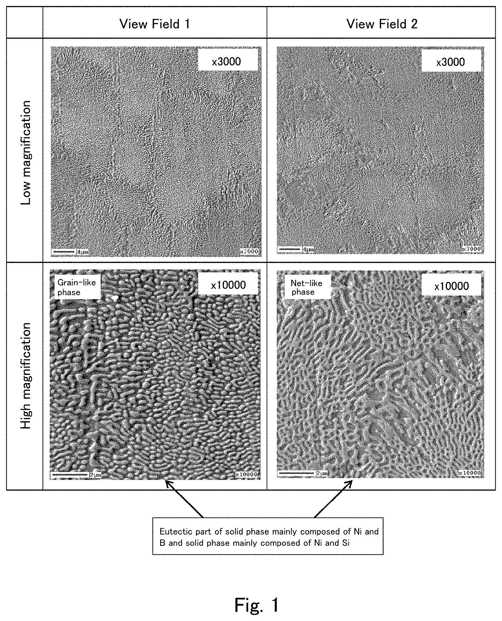
[0041] A specific method for measuring the average number of interfaces in the eutectic part in the present embodiment is described with reference to FIGS. 1 and 2. FIG. 1 shows secondary electron image photographs captured after Ar etching of a cross section of a cast material of an example (described later) using a field emission Auger microprobe (Auger). FIG. 1 shows the results obtained by photographing two sites (View Field 1 and View Field 2) in the cross section of the cast material at magnifications of .times.3,000 and .times.10,000. FIG. 2 is an enlarged view of a part of the higher magnification image (.times.10,000) of View Field 1 shown in FIG. 1.
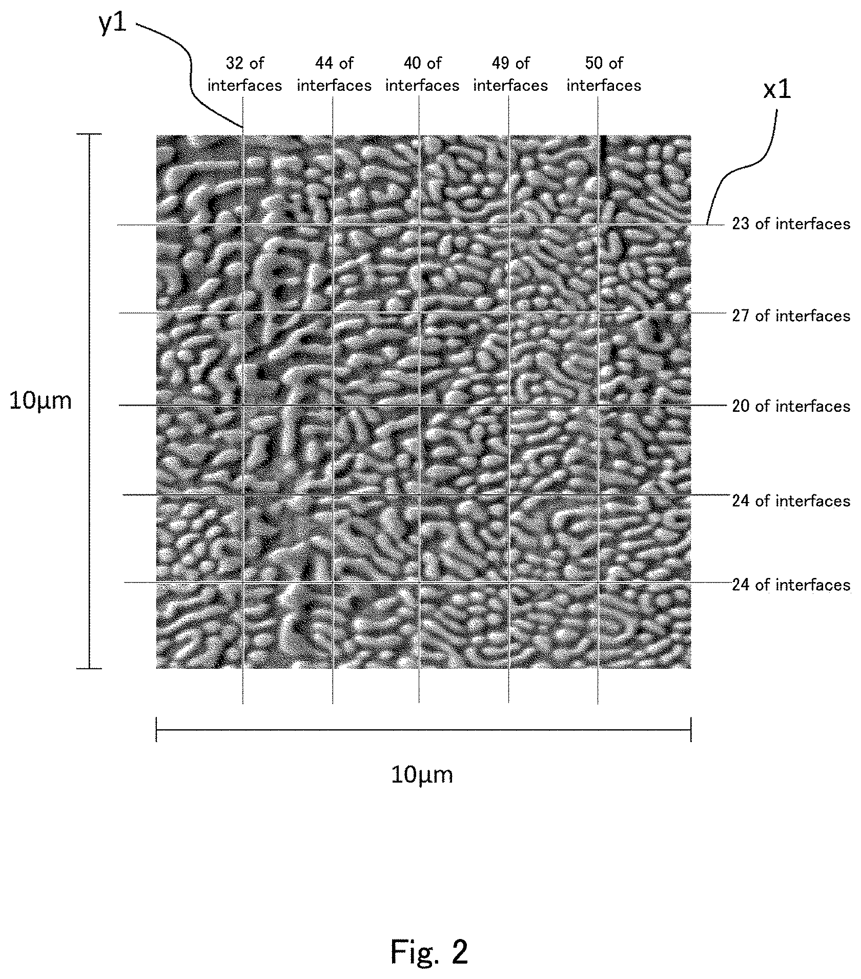
[0042] In the present embodiment, as shown in FIG. 2, a straight line is drawn on the secondary electron image, and the average number of interfaces between the solid phase (NiB phase) mainly made of Ni and B and the solid phase (NiSi phase) mainly made of Ni and Si on the straight line is determined. For example, comparatively white portions (portions which look protruding) correspond to the NiB phase, and comparatively black portions (portions which look recessed) correspond to the NiSi phase in FIG. 2. The NiB phase and the NiSi phase in the secondary electron image can be specified by measuring the cast material by Auger electron spectroscopy (AES) to identify the elements, and specifying the NiB phase and the NiSi phase based on the results thereof. For example, the number of interfaces on the straight line y1 in FIG. 2 is 32, and the number of interfaces on the straight line x1 is 23. The numbers of interfaces on other straight lines are also shown in FIG. 2. The secondary electron image of FIG. 2 has a size of 10 .mu.m (height).times.10 .mu.m (width). Accordingly, there are 32 interfaces on the 10 .mu.m-long section of the straight line y1 (3.2 interfaces /.mu.m of length), and there are 23 interfaces on the 10 .mu.m-long section of the straight line x1 (2.3 interfaces /.mu.m of length). On the straight lines y1 and x1, 55 interfaces are present along the total length of 20 .mu.m. The average number of interfaces per .mu.m of length based on the two straight lines is 2.75 /.mu.m.
[0043] In the present embodiment, the average number of interfaces in the eutectic part can be determined by determining the average number of interfaces on at least one straight line in the surface or the cross section of the cast material. A preferred method for determining the average number of interfaces is to draw a plurality of straight lines (for example, five straight lines) in the surface or the cross section of the cast material, and calculate the average of the numbers of interfaces per .mu.m of length of the respective straight lines. In this case, it is particularly preferred to draw two straight lines perpendicular to each other like the straight lines y1 and x1 in FIG. 2, and determine the average number of interfaces per .mu.m of length based on the number of interfaces on one of the two perpendicular straight lines and the number of interfaces on the other of the two perpendicular straight lines. This method enables more accurate determination of the average number of interfaces even when the NiB phase and the NiSi phase are localized in the eutectic part. When the average number of interfaces is determined based on such perpendicular straight lines, it is also preferred to draw a plurality of straight lines (for example, five straight lines) in one direction (for example, the direction of the straight line y1) and a plurality of straight lines (for example, five straight lines) in the other direction (for example, the direction of the straight line x1), and calculate the average number of interfaces per .mu.m of length based on the numbers of interfaces on these straight lines.
[0044] A conventionally known method for manufacturing a cast material is to introduce a raw material powder into a mold and heat the raw material powder in a heating furnace. Unfortunately, this method may result in a cast material having insufficient bending strength.
[0045] The present inventors have found that in conventional cast materials, as a result of slow cooling in a mold after heating in a heating furnace, crystals may grow to an excessively large particle size, dendrite structures may grow therein, and consequently the bending strength of the cast materials may be reduced. Based on this finding, the present inventors have found that the bending strength of a cast material can be remarkably improved by controlling the state of crystals in a eutectic part in the cast material.
[0046] In the present embodiment, any method for controlling the average number of interfaces in the eutectic part can be used without limitation. Examples thereof include a method including: melting a raw material powder and the like for forming a cast material to prepare a raw material melt; and cooling the raw material melt under predetermined conditions, as described below.
[0047] The cast material of the present embodiment may contain hard phase particles mainly composed of a boride. When the cast material contains such hard phase particles, the hard phase particles are dispersed in a Ni-based alloy matrix including the above-described eutectic part.
[0048] The boride constituting the hard phase particles is not particularly limited, and examples thereof include MB-type, MB.sub.2-type, M.sub.2B-type, M.sub.2B.sub.5-type, and M.sub.2M' B.sub.2-type borides (where M and M' each represent at least one metal of Ni, Co, Cr, Mo, Mn, Cu, W, Fe, and Si, and M' represents a metal element different from M). Specific examples thereof may include multiple borides such as CrB, MoB, Cr.sub.2B, Mo.sub.2B, Mo.sub.2B.sub.5, Mo.sub.2FeB.sub.2, Mo.sub.2CrB.sub.2, Mo.sub.2NiB.sub.2, and Mo(Ni,Cr)B.sub.2.
<Composition of Cast Material>
[0049] The composition of the cast material of the present embodiment is not particularly limited, but preferably includes 0.01 to 0.06% by weight of C, 1 to 6% by weight of B, 3 to 10% by weight of Si, and 0.05 to 1.5% by weight of Fe, with the remainder being Ni.
[0050] B (boron) is an element for forming the NiB phase in the above-described eutectic part. When the content of B therein is within the above range, the wear resistance, the hardness, and the bending strength of the cast material can be improved. The content of B in the cast material is preferably 1 to 6% by weight, more preferably 2 to 5% by weight.
[0051] C (carbon) improves the hardness and the bending strength of the cast material when present in the form of a carbide in the cast material. When it does not form a carbide, and is contained as an inevitable impurity, the amount thereof is preferably 0.06% or less, for example.
[0052] Ni (nickel) is an element for forming the above-described eutectic part. When the content of Ni in the cast material is within the above range, the corrosion resistance of the cast material can be improved.
[0053] Si (silicon) is an element for forming the NiSi phase in the above-described eutectic part, and acts to reduce the melting temperature of the raw material for forming the cast material. When the content of Si therein is appropriate, Si not only acts to reduce the melting temperature but also prevents a reduction in the bending strength of the cast material which is caused by excessive silicides contained in the cast material.
[0054] Fe (iron) improves the hardness and the bending strength of the cast material when it forms hard phase particles in the cast material. When it does not form hard phase particles, and is contained as an inevitable impurity, the amount thereof is preferably 1.5% or less, for example.
<Cast Material Manufacturing Method>
[0055] Next, the method for manufacturing the cast material of the present embodiment is described.
[0056] First, a raw material powder for forming the cast material of the present embodiment is prepared. The raw material powder is prepared in a desired compositional ratio of contained elements for forming the cast material. The raw material powder may be in the powder form, or may contain aggregates (bulk form) of powder.
[0057] Next, if necessary, in order to micronize the prepared raw material powder into a predetermined particle size, agents such as a binder and an organic solvent are added to the raw material powder, and the resulting mixture is mixed and pulverized using a pulverizer (e.g., a ball mill).
[0058] The binder is added to improve moldability during molding and prevent oxidation of the powder. The binder is not particularly limited, and known binders can be used. Examples thereof include paraffin. The amount of the binder to be added is not particularly limited, but is preferably 3 to 6 parts by weight relative to 100 parts by weight of the raw material powder. The organic solvent is not particularly limited, and low-boiling-point solvents such as acetone can be used. The pulverization-mixing time is not particularly limited, but is typically 15 to 30 hours.
[0059] Next, the above-described raw material powder is melted to prepare a raw material melt, and impurities such as gas and oxides are then removed if necessary. In this process, the melting temperature can be determined according to the raw material used, and is preferably 1100.degree. C. to 1300.degree. C., more preferably 1200.degree. C. to 1250.degree. C.
[0060] Subsequently, the raw material melt thus prepared can be casted into a cast material by pouring the raw material melt into a cast material mold such as a mold of a desired shape, and then cooling the raw material melt.
[0061] In the present embodiment, the step of cooling the raw material melt includes continuously cooling the raw material melt at a cooling rate of 100.degree. C./min or more over the temperature range of the cooling start temperature to 400.degree. C. In the present embodiment, the expression "includes continuously cooling the raw material melt at a cooling rate of 100.degree. C./min or more" means that the cooling rate is continuously controlled to 100.degree. C./min or more for a certain period of time. The cooling step preferably includes cooling at a cooling rate of 100.degree. C./min or more for 1 minute or more, more preferably 5 minutes or more. For example, a case where the cooling rate instantaneously reaches 100.degree. C./min or more (for example, a case where the cooling rate reaches 100.degree. C./min or more for 1 second or less) is not included. Although it is sufficient that the step of cooling the raw material melt includes continuously cooling the raw material melt at a cooling rate of 100.degree. C./min or more over the temperature range of the cooling start temperature to 400.degree. C., the cooling rate is preferably 200.degree. C./min or more, more preferably 400.degree. C./min or more. When the raw material melt is cooled under the above conditions, the average number of interfaces between the NiB phase and the NiSi phase in the eutectic part can be controlled within the above range.
[0062] In the present embodiment, any method for cooling the raw material melt under the above conditions can be used without limitation. Examples thereof include a method including pouring the raw material melt into a mold preferably at room temperature to 110.degree. C., more preferably 300.degree. C. to 1100.degree. C., and cooling the raw material melt. The room temperature is, for example, 1.degree. C. to 30.degree. C.
[0063] Any casting method can be used without limitation, but casting methods such as mold casting, lost-wax casting, continuous casting, and centrifugal casting are preferably used because these methods enables formation of cast materials having complicated shapes and formation of thick-walled cast materials.
[0064] In the present embodiment, the cast material cooled under the above conditions may be further subjected to a heat treatment. The heat treatment can reduce a variation in the bending strength of the entire cast material obtained, and thereby can further stabilize the quality of the cast material. The reason for this is not clearly understood, but it is assumed that crystals including Ni.sub.3B and Ni.sub.3Si which constitute the eutectic part are further stabilized because, for example, the heat treatment promotes the diffusion of atoms in the eutectic part in the cast material in such a manner as to eliminate a disturbed arrangement of atoms in the eutectic part (for example, when Si is contained in the NiB phase, the heat treatment causes Si in the NiB phase to diffuse, thereby reducing the content of Si in the NiB phase).
[0065] The temperature for the heat treatment of the cast material is preferably 700.degree. C. to 950.degree. C., more preferably 750.degree. C. to 900.degree. C., further preferably 800.degree. C. to 850.degree. C. When the temperature for the heat treatment is within the above range, a disturbed arrangement of atoms in the eutectic part can be eliminated, the variation in the bending strength of the entire cast material obtained can be reduced, and the quality of the cast material can be further stabilized. Too high a temperature in the heat treatment, specifically a temperature higher than 1,000.degree. C. melts the cast material and deforms the cast material.
[0066] The treatment time for the heat treatment of the cast material is preferably 0.17 to 3 hours, more preferably 0.33 to 2 hours, further preferably 0.5 to 1.5 hours. When the treatment time for the heat treatment is within the above range, a disturbed arrangement of atoms in the eutectic part can be eliminated, the variation in the bending strength of the entire cast material obtained can be reduced, and the quality of the cast material can be further stabilized.
[0067] The cast material of the present invention is manufactured as described above.
[0068] The cast material of the present embodiment is a Ni--B--Si three-element-based cast material containing a eutectic part comprising a solid phase mainly composed of Ni and B and a solid phase mainly composed of Ni and Si, wherein when a straight line is drawn in a surface or a cross section of the eutectic part, the average number of interfaces formed between the solid phase mainly composed of Ni and B and the solid phase mainly composed of Ni and Si on the straight line is 2.0 /.mu.m or more. Because of this structure, the cast material of the present embodiment has excellent corrosion resistance and excellent wear resistance, and has high hardness and high bending strength.
[0069] The cast material of the present embodiment can be suitably used as a wear resistant material that can exhibit excellent durability even in environments under a high load (e.g., rolls, cylinders, bearings, industrial pump components, and the like) because it has excellent corrosion resistance and excellent wear resistance, and has high hardness and high bending strength.
Second Embodiment
[0070] Hereinafter, a cast material of the second embodiment is described.
[0071] The cast material of the present embodiment is a cast material comprising hard phase particles mainly composed of a boride and a binder phase containing an alloy containing Ni, Si, and B, wherein the average particle size of the hard phase particles is 3 .mu.m or less, the average aspect ratio of the hard phase particles is 2.0 or less, the contact ratio between the hard phase particles is 35% or less, the binder phase contains Ni.sub.3Si and Ni.sub.3B, and the cast material has an intensity ratio I.sub.A/I.sub.B of 1/10 or less, where I.sub.A is the intensity of a peak derived from Ni.sub.31Si.sub.12 observed at a diffraction angle 2.theta. within the range of 46.8.degree. to 47.8.degree., and I.sub.B is the intensity of a peak derived from Ni.sub.3Si observed at a diffraction angle 2.theta. within the range of from 44.0.degree. to 45.0.degree., the intensities being determined by X-ray diffraction measurement using CuK.alpha. radiation.
<Hard Phase Particles>
[0072] The hard phase particles constituting the cast material of the present embodiment mainly contain a boride, and contribute to the hardness and the wear resistance of the cast material. In the cast material of the present embodiment, the hard phase particles are dispersed in a binder phase matrix described below.
[0073] The boride constituting the hard phase particles is not particularly limited, and examples thereof include MB-type, MB.sub.2-type, M.sub.2B-type, M.sub.2B.sub.5-type, and M.sub.2M' B.sub.2-type borides (where M and M' each represent at least one metal of Ni, Co, Cr, Mo, Mn, Cu, W, Fe, and Si, and M' represents a metal element different from M). Specific examples of thereof may include multiple borides such as CrB, MoB, Cr.sub.2B, Mo.sub.2B, M.sub.2B.sub.5, Mo.sub.2FeB.sub.2, Mo.sub.2CrB.sub.2, Mo.sub.2NiB.sub.2, and Mo.sub.2(Ni,Cr)B.sub.2.
[0074] The content of the hard phase particles in the cast material of the present embodiment is preferably 10 to 50 vol %, more preferably 20 to 45 vol %. A method that can be used to control the content of the hard phase particles in the cast material is to adjust the content of B in the cast material. When the content of the hard phase particles is within the above range, the cast material of the present embodiment has well-balanced mechanical strengths such as corrosion resistance, wear resistance, hardness, and bending strength. Additionally, when the content of the hard phase particles is within the above range, an excessive increase in the contact ratio between the hard phase particles can be prevented, preventing a reduction in the bending strength of the cast material which is caused by aggregation of hard phase particles. Moreover, when the content of the hard phase particles is within the above range, the temperature required to melt the raw materials of the hard phase particles can be reduced. This leads to a reduction in heat energy necessary for melting, and provides an advantage in cost.
<Binder Phase>
[0075] The binder phase in the cast material of the present embodiment contains an alloy containing Ni, Si, and B, and forms a matrix for connecting the hard phase particles. Among other alloys containing Ni, Si, and B, the binder phase in the cast material of the present embodiment contains Ni.sub.3Si and Ni.sub.3B. In the cast material of the present embodiment, the presence of Ni.sub.3Si and Ni.sub.3B in the binder phase remarkably improves the hardness and the bending strength of the cast material, and improves the corrosion resistance of the resulting cast material compared to a case where the binder phase contains an alloy mainly composed of an Fe-based alloy or the like.
[0076] Additionally, the binder phase in the cast material of the present embodiment is controlled such that the content of Ni.sub.3Si in the binder phase determined by X-ray diffraction measurement is within a predetermined range. Specifically, when measured with an X-ray diffraction measurement device using CuK.alpha. radiation, the cast material of the present embodiment has an intensity ratio I.sub.A/I.sub.B of 1/10 or less, preferably 1/100 or less, more preferably 1/300 or less. The intensity ratio I.sub.A/I.sub.B is the ratio of the intensity I.sub.A of a peak derived from Ni.sub.31Si, observed at a diffraction angle 26 within the range of 46.8.degree. to 47.8.degree. to the intensity I.sub.B of a peak derived from Ni.sub.3Si and observed at a diffraction angle 2.theta. within the range of from 44.0.degree. to 45.0.degree.. When the intensity ratio I.sub.A/I.sub.B is 1/10 or less, the bending strength of the resulting cast material can be remarkably improved.
[0077] A conventionally known method for manufacturing a cast material is to place a raw material powder containing Mo, Ni, and B into a mold, and heat the raw material powder in a furnace. This method, however, may provide a cast material containing hard phase particles having a too large average particle size, a too large aspect ratio, and a too large contact ratio because the cast material is slowly cooled in the mold. Unfortunately, the hardness and the bending strength of the cast material may be insufficient.
[0078] In contrast, the present inventors have found that when a cast material is manufactured by melting a mixed raw material powder containing Mo, Ni, and B to prepare a melt mixture, pouring the melt mixture into a mold, and cooling the melt mixture while controlling the cooling rate within a predetermined range higher than that of the conventional method, the average particle size of the hard phase particles, the average aspect ratio of the hard phase particles, and the contact ratio between the hard phase particles of the obtained cast material can be controlled within the respective ratios described above, and as a result, the hardness and the bending strength of the cast material can be remarkably improved.
[0079] The present inventors have also found that although the hardness and the bending strength of the cast material can be remarkably improved by controlling the cooling rate within a higher range than that of the conventional method, the bending strength of the cast material may be reduced depending on the morphology of crystals composed of Mo, Ni, B, and the like contained in the cast material. Specifically, the present inventors have found that when crystals including a stable phase Ni.sub.3Si, a metastable phase Ni.sub.31Si.sub.12, and the like are present in the cast material, and when the content ratio of Ni.sub.31Si.sub.12 to Ni.sub.3Si is too high (an excessive amount of the metastable phase Ni.sub.31Si.sub.12 is crystallized), high internal strain energy is generated due to the metastable phase Ni.sub.31Si.sub.1, and as a result, the cast material may have reduced bending strength, and may readily break. In contrast, the present inventors have found that the bending strength of the resulting cast material can be remarkably improved by controlling the content ratio of Ni.sub.31Si.sub.12 to Ni.sub.3Si in the cast material, specifically, controlling the intensity ratio I.sub.A/I.sub.B (where I.sub.A is the intensity of a peak derived from Ni.sub.31Si.sub.12 observed at a diffraction angle 2.theta. within the range of 46.8.degree. to 47.8.degree., and I.sub.B is the intensity of a peak derived from Ni.sub.3Si observed at a diffraction angle 2.theta. within the range of from 44.0.degree. to 45.0.degree., the intensities being determined by X-ray diffraction measurement using CuK.alpha. radiation) within the above range. Based on this finding, the present inventors have completed the present invention.
[0080] In the present embodiment, any method for controlling the intensity ratio I.sub.A/I.sub.B of the cast material within the above range can be used without limitation, and examples thereof include a method including melting a raw material powder and the like for forming the cast material to prepare a melt mixture, cooling the melt mixture under predetermined conditions, and subjecting the cast material to a heat treatment at a temperature of 700.degree. C. to 950.degree. C., as described later.
[0081] FIGS. 10(A) and 10(B) show examples of diffraction patterns actually obtained by X-ray diffraction measurement of cast materials using CuK.alpha. radiation. Specifically, the cast materials were prepared by heating and hardening a raw material powder for forming a cast material using a vacuum furnace at 1160.degree. C. for 30 minutes to prepare an ingot, melting the ingot by heating to 1200.degree. C. in air using an air atmosphere furnace to prepare a melt mixture, pouring the melt mixture into a mold at room temperature, and air cooling the melt mixture to room temperature. One cast material was subjected to the heat treatment at 800.degree. C. for 1 hour, and the measurement results thereof are shown in FIG. 10(A). The measurement results of the other cast material not subjected to the heat treatment are shown in FIG. 10(B).
[0082] FIGS. 10(A) and 10(B) show that the cast material of FIG. 10(B), which was not subjected to the heat treatment, had a relatively small ratio of the intensity I.sub.Q, which is the intensity of the peak derived from the stable phase Ni.sub.3Si (2.theta.=46.8.degree. to 47.8.degree.), to the intensity I.sub.A, which is the intensity of the peak derived from the metastable phase Ni.sub.31Si.sub.12 (2.theta.=46.8.degree. to 47.8.degree.). Namely, the results show that the content of the stable phase Ni.sub.3Si is relatively low, and the content of the metastable phase Ni.sub.31Si.sub.12 is relatively high.
[0083] In contrast, in the cast material of FIG. 10(A), which was subjected to the heat treatment, the heat treatment at 800.degree. C. for 1 hour caused a phase transition from the metastable phase (Ni.sub.31Si.sub.12) to the stable phase (Ni.sub.3Si), so that the intensity I.sub.B of the peak derived from the stable phase Ni.sub.3Si (2.theta.=44.0 to 45.0) became large relative to the intensity I.sub.A of the peak derived from the metastable phase Ni.sub.31Si.sub.12 (2.theta.=46.8 to 47.8). Namely, the results show that the content of the stable phase Ni.sub.3Si is relatively high, and the content of the metastable phase Ni.sub.31Si.sub.12 is relatively low.
[0084] In the present embodiment, the bending strength of the obtained cast material can be remarkably improved by controlling, within the above range, the intensity ratio I.sub.A/I.sub.B of the intensity I.sub.A of a peak derived from Ni.sub.31Si.sub.12 to the intensity I.sub.B of a peak derived from Ni.sub.3Si, the intensities being determined by X-ray diffraction measurement using CuK.alpha. radiation.
[0085] In the present embodiment, the intensity ratio I.sub.A/I.sub.B based on X-ray diffraction measurement using CuK.alpha. radiation can be determined, for example, as follows. First, the cast material is subjected to X-ray diffraction measurement under the conditions: X-ray source: Cu, 40 kV, 200 mA, emission slit: 2.degree., scattering slit: 1.degree., and receiving slit: 0.3 mm. Based on the data obtained by the X-ray diffraction measurement, a peak derived from Ni.sub.31Si.sub.12 observed at a diffraction angle 2.theta. within the range of 46.8.degree. to 47.8.degree. and a peak derived from Ni.sub.3Si observed at a diffraction angle 2.theta. within the range of 44.0.degree. to 45.0.degree. are determined. The intensities I.sub.A and I.sub.B of these peaks from which background is removed are determined (where I.sub.A is the intensity of the peak observed at a diffraction angle 2.theta. within the range of 46.8.degree. to 47.8.degree., and I.sub.B is the intensity of the peak observed at a diffraction angle 2.theta. within the range of 44.0.degree. to 45.0.degree.), and the ratio therebetween is calculated to determine the intensity ratio I.sub.A/I.sub.B. Another peak derived from Ni.sub.3Si also appears at a 2.theta. of about 35.6.degree. to 36.6.degree. in addition to the peak in the diffraction angle 2.theta. range of 46.8.degree. to 47.8.degree.. However, the peak at a 2.theta. of about 35.6.degree. to 36.6.degree. has a relatively small intensity. Therefore, in the present embodiment, the peak in the diffraction angle 2.theta. range of 46.8.degree. to 47.8.degree. is detected as a peak derived from Ni.sub.3Si.
[0086] Among the above-described features of the hard phase particles and the binder phase constituting the cast material of the present embodiment, it is particularly preferable that the binder phase contain Ni.sub.3Si and Ni.sub.3B, and the hard phase particles comprise at least one of multiple borides represented by Mo.sub.2NiB.sub.2 and Mo.sub.2(Ni,Cr)B.sub.2.
<Microstructure of Cast Material>
[0087] In the cast material of the present embodiment, the average particle size of the hard phase particles, the average aspect ratio of the hard phase particles, and the contact ratio between the hard phase particles are controlled within predetermined ranges described later, and the binder phase contains Ni.sub.3Si and Ni.sub.3B. According to the present embodiment, by controlling these properties within the predetermined ranges described later, it is possible to provide a cast material having excellent corrosion resistance and excellent wear resistance and having high hardness and high bending strength.
[0088] In the cast material of the present embodiment, the average particle size of the hard phase particles is 3 .mu.m or less, preferably 2.8 .mu.m or less, more preferably 2.5 .mu.m or less. When the average particle size of the hard phase particles is controlled within the above range, the resulting cast material has sufficient hardness and bending strength. When the average particle size of the hard phase particles is too large, the cast material, unfortunately, may break from the hard phase particles, and may have remarkably reduced bending strength. The lower limit of the average particle size of the hard phase particles is not particularly limited, but is preferably 0.5 .mu.m. In order to control the average particle size of the hard phase particles to less than 0.5 .mu.m, the cooling rate should be remarkably high. Such a rate may not be achieved by typical techniques such as water cooling. Therefore, even if attempted to achieve this rate, the manufacturing cost will be increased.
[0089] The average particle size of the hard phase particles can be determined, for example, by calculating the equivalent circle diameters of hard phase particles, and calculating the average of the calculated equivalent circle diameters. Specifically, a reflection electron image of a cross section of the cast material is captured using a scanning electron microscope (SEM), and the average particle size of the hard phase particles is calculated using the captured reflection electron image based on Fullaman's formula (equation (1) shown below).
d.sub.m=(4/.pi.).times.(N.sub.L/N.sub.S) (1)
In the equation (1), do is the average particle size of the hard phase particles. n is the ratio of the circumference of a circle. N.sub.L is the number of hard phase particles hit by an arbitrary straight line on a cross section of the structure (the number of hard phase particles touched or crossed by a straight line arbitrarily drawn) per unit length of the arbitrary straight line. Specifically, N.sub.L is determined by dividing the number of particles hit by an arbitrary straight line having a length L in a cross section of the structure by the length L of the arbitrary straight line. N.sub.S represents the number of hard phase particles included in an arbitrary unit area, and is a value obtained by dividing the number of particles included in an arbitrary measurement region S having a measurement area by the arbitrary measurement region S. In this case, the straight line L should be long enough to cross a number of hard phase particles sufficient for measurement of the average particle size, and the length thereof is preferably 20 .mu.m or more, and may be 100 .mu.m, for example. The measurement region S should be large enough to include a number of hard phase particles sufficient for measurement of the average particle size, and is preferably 20 .mu.m or more in length and 20 .mu.m or more in width.
[0090] The average aspect ratio, that is, the average ratio (major diameter/minor diameter) of the major diameter to the minor diameter of the hard phase particles of the cast material according to the present embodiment is 2.0 or less, preferably 1.9 or less, more preferably 1.8 or less. When the average aspect ratio of the hard phase particles is within the above range, the bending strength of the cast material can be remarkably improved. When the average aspect ratio of the hard phase particles is too large due to growth of dendrite structures (columnar crystals) of the hard phase particles, for example, the cast material has reduced bending strength in the dendrite structures, and may readily break.
[0091] The average aspect ratio of the hard phase particles can be determined, for example, in accordance with JIS R1670 as follows. First, the cast material is cut, and a reflection electron image of the cut surface is captured using a scanning electron microscope (SEM). Then, a predetermined number of hard phase particles are randomly selected from the measurement region S (a region having a length of 20 .mu.m or more and a width of 20 .mu.m or more) in the same manner as when the average particles size is measured, and each particle is measured for the length (major diameter) of the longest part and the length (minor diameter) of the longest part extending in the direction perpendicular to the major diameter. The ratio of the major diameter to the minor diameter can be determined from the measured major diameter and minor diameter as the aspect ratio of the hard phase particle. In the present embodiment, the aspect ratio is determined for a predetermined number of hard phase particles (for example, 10 or more particles), and the average thereof can be determined as the average aspect ratio of the hard phase particles.
[0092] The contact ratio (contiguity) between the hard phase particles of the cast material of the present embodiment is 35% or less, preferably 30% or less, more preferably 25% or less. The contact ratio between the hard phase particles is a measure of the dispersibility of the hard phase particles. A lower contact ratio corresponds to higher dispersibility, and provides improved strength. When the contact ratio between the hard phase particles is too high, the hard phase particles may contact each other to form bulk aggregates, and the hard phase particles may bond to each other, resulting in growth of particles. Unfortunately, as a result, the cast material may break from a portion with grown particles, and may have reduced bending strength.
[0093] The contact ratio between the hard phase particles can be determined, for example, as follows. First, a reflection electron image of the surface of the cast material is captured using a scanning electron microscope. As shown in FIG. 9, a measurement line L having a predetermined length is arbitrarily drawn on the reflection electron image in the same manner as when the average particle size is measured, and the interfaces between hard phases on the line L are observed. FIG. 9 is a view for illustrating how to measure the microstructure of the cast material of the present embodiment. Specifically, the interfaces between hard phase particles are observed. An interface between hard phase particles in contact with each other is referred to as a hard phase-hard phase interface I.sub.HH, and an interfaces between a hard phase particle and the binder phase in contact with each other is referred to as a hard phase-binder phase interface I.sub.HB. These interfaces are counted. The term "hard phase particle" refers to a particle which is composed of a boride, and is generated and grows during heating of a raw material containing Mo, Ni, Cr, B and the like, as described later. When grown particles are in contact with each other, these particles do not form a single integrated particle, but are present as separate particles in contact with each other. A method for extracting the contours of the hard phase particles and the interfaces between hard phase particles in contact with each other is described with reference to FIG. 11(A), which is one exemplary reflection electron image obtained by imaging the surface of the cast material using a scanning electron microscope (SEM). In the reflection electron image shown in FIG. 11(A), white regions each correspond to the hard phase (boride), and grey regions each correspond to the binder phase. In such a reflection electron image, the contour of each hard phase can be detected, as shown in FIG. 11(B), by detecting the boundaries between the white regions and the grey regions based on the difference in brightness therebetween. Recesses (portions having an inner angle of 1800 or more) of the detected contour of the hard phase are detected, and a straight line which connects a pair of facing recesses is extracted as the interface between hard phase particles in contact with each other. Specifically, as shown in FIG. 11(C), which is an enlarged view of the encircled area in FIG. 11(B), pairs of facing recesses are connected by straight lines, and the line segments (line segments indicated by a, b, c and d in FIG. 11(C)) can be defined as interfaces where hard phase particles are in contact with each other.
[0094] In the present embodiment, the contact ratio Cont (unit: %) between the hard phase particles can be calculated in accordance with the following equation (2) based on the number N(I.sub.H) of hard phase-hard phase interfaces I.sub.HH per unit length of L1 and the number N(I.sub.HB) of hard phase-binder phase interfaces I.sub.HB per unit length of L1.
Cont=2N(I.sub.HH)/[2N(I.sub.HH+N(I.sub.HB)].times.100 (2)
[0095] When the contact ratio between the hard phase particles is calculated in the manner described above, it is preferable to repeat the following operation five times, and calculate the contact ratio between the hard phase particles based on the results of the five-time measurement: the operation comprising drawing another measurement line L different from the above line on the SEM photograph such that the line L runs a different part from the part through which the above line runs; and counting hard phase-hard phase interfaces I.sub.HH and hard phase-binder phase interfaces I.sub.HB in the same manner as above.
[0096] In the present embodiment, any method for controlling the average particle size of the hard phase particles, the average aspect ratio of the hard phase particles, and the contact ratio of the hard phase particles within the above ranges can be used without limitation. Examples thereof include a method including melting a raw material powder and the like for forming the cast material to prepare a melt mixture, and then cooling the melt mixture under predetermined conditions, as described later.
[0097] The contact ratio between the hard phase particles can also be controlled by adjusting the compositional ratio of the cast material within a predetermine range.
[0098] The binder phase of the cast material of the present embodiment contains Ni.sub.3Si and Ni.sub.3B, as described above. Since the binder phase contains Ni.sub.3Si and Ni.sub.3B, in particular, the stable phase Ni.sub.3Si, the bending strength of the cast material can be remarkably improved. The formation of crystals of the metastable phase Ni.sub.31Si.sub.12 in the binder phase increases the internal strain energy in the cast material. As a result, the cast material may have reduced bending strength, and may readily break.
[0099] In addition, the cast material of the present embodiment has an intensity ratio I.sub.A/I.sub.B of 1/10 or less, where I.sub.A is the intensity of a peak derived from Ni.sub.31Si.sub.12 observed at a diffraction angle 2.theta. within the range of 46.8.degree. to 47.8.degree., and I.sub.B is the intensity of a peak derived from Ni.sub.3Si observed at a diffraction angle 2.theta. within the range of from 44.0.degree. to 45.0.degree., the intensities being determined by X-ray diffraction measurement using CuK.alpha. radiation. When the intensity ratio I.sub.A/I.sub.B is within the above range, that is, the ratio of the content of the stable phase Ni.sub.3Si to the content of the metastable phase Ni.sub.31Si.sub.12 is relatively high, the bending strength of the resulting cast material can be remarkably improved.
<Composition of Cast Material>
[0100] The composition of the cast material of the present embodiment is not particularly limited. When the binder phase comprises a Ni-based alloy mainly composed of Ni, the composition is preferably composed of 1 to 6% by weight of B, 0 to 5% by weight of Si, 0 to 20% by weight of Cr, and 5 to 40% by weight of Mo, with the remainder being Ni.
[0101] B (boron) is an element which forms a boride, which in turn forms hard phase particles. When the content of B is within the above range, the content of the hard phase particles in the cast material can be controlled adequately. As a result, the wear resistance of the cast material can be improved. In addition, when the content of B is within the above range, the contact ratio between the hard phase particles can be controlled within the above range, improving the hardness and the bending strength of the cast material. The content of B in the cast material is preferably 1 to 6% by weight, more preferably 2 to 5% by weight.
[0102] Ni is an element which can be incorporated in the hard phase particles when a Ni-based alloy is used for the binder phase of the cast material, and is also an element for forming the binder phase. Ni acts to improve the corrosion resistance of the cast material.
[0103] Si is an element for forming the binder phase of the cast material, and acts to reduce the melting temperature of the raw material for forming the cast material. When the content of Si is adequate, it is possible not only to reduce the melting temperature but also to prevent a reduction in the bending strength of the cast material which is caused by excessive silicides contained in the cast material.
[0104] Cr is an element which can be incorporated in the hard phase particles, and also can be incorporated in the binder phase. Cr acts to improve the corrosion resistance, the wear resistance, the high-temperature characteristics, the hardness and the bending strength of the cast material. When the content of Cr is adequate, the content of the hard phase particles in the cast material is controlled within the above range, resulting in improved bending strength of the cast material.
[0105] Mo is an element which can be incorporated in the hard phase particles, and also can be incorporated in the binder phase. Mo acts to improve the corrosion resistance of the cast material. Specifically, a portion of Mo is present as a solid solution in the binder phase, thereby improving the corrosion resistance of the cast material. When the content of Mo is adequate, the wear resistance and the corrosion resistance of the cast material can be improved.
<Cast Material Manufacturing Method>
[0106] Next, the method for manufacturing the cast material of the present embodiment is described.
[0107] First, a raw material powder for forming the cast material of the present embodiment is prepared. The raw material powder is prepared in a desired compositional ratio of the elements for forming the cast material. The raw material powder may be in the form of powder or may contain aggregates (bulk form) of powder. In the present embodiment, in the raw material powder, the hard phase particles mainly composed of a boride may be preliminarily contained. Alternatively, in the raw material powder, the hard phase particles may not be contained, and boron and carbon in the raw material powder may form the hard phase particles mainly composed of a boride in the cast material in the process of manufacture of the cast material using the raw material powder. It is preferred that the hard phase particles mainly composed of a boride be preliminarily contained in the raw material powder. The boride contained in the raw material powder is preferably at least one of multiple borides represented by Mo.sub.2NiB.sub.2 and Mo.sub.2(Ni,Cr)B.sub.2, particularly preferably Mo.sub.2(Ni,Cr)B.sub.2. When the boride contains Cr in the form of Mo.sub.2(Ni,Cr)B.sub.2, for example, the boride tends to have a tetragonal crystalline structure. Because of this structure, the boride prevents the growth of the boride crystals into a larger size, and further improves the characteristics of the resulting cast material compared to Cr-free borides which tend to have an orthorhombic crystalline structure.
[0108] Next, a binder, an organic solvent, and the like are added to the prepared raw material powder to micronize the raw material powder into a predetermined particle size if necessary, and the mixture is mixed and pulverized using a pulverized such as a ball mill.
[0109] The binder is added to improve the moldability during molding and prevent oxidation of the powder. The binder is not particularly limited, and known binders can be used. Examples thereof include paraffin. The amount of the binder to be added is preferably 3 to 6 parts by weight relative to 100 parts by weight of the raw material powder. The organic solvent is not particularly limited, and low-boiling-point solvents such as acetone can be used. The pulverizing/mixing time is not particularly limited, and can be selected such that hard phase particle having an average particle size within the above range are formed in the resulting cast material. The pulverizing/mixing time is typically 15 to 30 hours.
[0110] Next, the raw material powder is melted into a melt mixture, and impurities such as gas and oxides are removed from the melt mixture if necessary. In this process, the melting temperature is determined according to the materials used, and is preferably 1100.degree. C. to 1300.degree. C., more preferably 1200.degree. C. to 1250.degree. C.
[0111] Next, the melt mixture obtained as described above can be casted into a cast material by pouring the melt mixture into a cast material mold such as a mold of desired shape, and then cooling the melt mixture.
[0112] In the present embodiment, the step of cooling the melt mixture includes continuously cooling the melt mixture at a cooling rate of 100.degree. C./min or more over the temperature range of the cooling start temperature to 400.degree. C. In the present embodiment, the expression "includes continuously cooling the melt mixture at a cooling rate of 100.degree. C./min or more" means that the cooling rate is continuously controlled to 100.degree. C./min or more for a certain period of time. The cooling step preferably includes cooling at a cooling rate of 100.degree. C./min or more for 1 minute or more, more preferably 5 minutes or more. For example, a case where the cooling rate instantaneously reaches 100.degree. C./min or more (for example, a case where the cooling rate reaches 100.degree. C./min or more for 1 second or less) is not included. Although it is sufficient that the step of cooling the melt mixture includes continuously cooling the melt mixture at a cooling rate of 100.degree. C./min or more over the temperature range of the cooling start temperature to 400.degree. C., the cooling rate is preferably 200.degree. C./min or more, more preferably 400.degree. C./min or more. When the melt mixture is cooled under the above conditions, the average particle size of the hard phase particles, the average aspect ratio of the hard phase particles, and the contact ratio between the hard phase particles of the resulting cast material can be controlled within the above ranges.
[0113] In the present embodiment, any method for cooling the melt mixture can be used without limitation, and an example thereof is to pour the melt mixture into a mold preferably having a temperature of room temperature to 1100.degree. C., more preferably 300.degree. C. to 1100.degree. C., and cool the melt mixture. The room temperature is, for example, 1.degree. C. to 30.degree. C.
[0114] Any casting method can be used without limitation, but casting methods such as mold casting, lost-wax casting, continuous casting, and centrifugal casting are preferably used because these methods enables formation of cast materials having complicated shapes and formation of thick-walled cast materials.
[0115] In the present embodiment, the cast material obtained by cooling under the above conditions is then subjected to a heat treatment at a temperature of 700.degree. C. to 950.degree. C. The heat treatment under such a condition causes a phase transition from the metastable phase (Ni.sub.31Si.sub.12) to the stable phase (Ni.sub.3Si), thereby remarkably improving the bending strength of the cast material.
[0116] The temperature for the heat treatment of the cast material is 700.degree. C. to 950.degree. C., as described above, and is preferably 750.degree. C. to 900.degree. C., more preferably 800.degree. C. to 850.degree. C. When the temperature for the heat treatment is within the above range, the phase transition from the metastable phase (Ni.sub.31Si.sub.12) to the stable phase (Ni.sub.3Si) successfully occurs, thereby resulting in improved bending strength of the cast material. When the temperature for the heat treatment is too high, specifically higher than 950.degree. C., the metastable phase (Ni.sub.31Si.sub.12) is generated again. At a temperature of higher than 1,000.degree. C., the cast material may melt and deform.
[0117] In the present embodiment, the temperature for the heat treatment of the cast material is 700.degree. C. to 950.degree. C., as described above, but preferably satisfies the following expression (1) in order to more successfully cause the phase transition from the metastable phase (Ni.sub.31Si.sub.12) to the stable phase (Ni.sub.3Si) in the cast material, and therefore to further improve the bending strength of the cast material.
-85.324x+966.13.ltoreq.y.ltoreq.-85.324x+1216.1 (1)
(In the expression (1), x is the content (unit: % by weight) of B in the cast material, and y is the temperature for the heat treatment.)
[0118] In the present embodiment, the temperature for the heat treatment of the cast material more preferably satisfies the following expression (2).
-85.324x+1016.1.ltoreq.y.ltoreq.-85.324x+1166.1 (2)
(In the expression (2), x is the content (unit: % by weight) of B in the cast material, and y is the temperature for the heat treatment.)
[0119] The treatment time for the heat treatment of the cast material is not particularly limited, and is preferably 0.17 to 3 hours, more preferably 0.33 to 2 hours, further preferably 0.5 to 1.5 hours. When the treatment time for the heat treatment is within the above range, the phase transition from the metastable phase (Ni.sub.31Si.sub.12) to the stable phase (Ni.sub.3Si) more successfully occurs in the cast material, thereby further improving the bending strength of the cast material.
[0120] The cast material of the present embodiment is manufactured as described above.
[0121] The cast material of the present embodiment contains the hard phase particles mainly composed of a boride and the binder phase containing an alloy containing Ni.sub.3Si and Ni.sub.3B. The average particle size of the hard phase particles is controlled to 3 .mu.m or less. The average aspect ratio of the hard phase particles is controlled to 2.0 or less. The contract ratio between the hard phase particles is 35% or less. The cast material has an intensity ratio I.sub.A/I.sub.B controlled to 1/10 or less, where I.sub.A is the intensity of a peak derived from Ni.sub.31Si.sub.1 observed at a diffraction angle 2.theta. within the range of 46.8.degree. to 47.8.degree., and I.sub.B is the intensity of a peak derived from Ni.sub.3Si observed at a diffraction angle 2.theta. within the range of 44.0.degree. to 45.0.degree., the intensities being determined by X-ray diffraction measurement using CuK.alpha. radiation. Due to these features, the cast material of the present embodiment has excellent corrosion resistance and excellent wear resistance, and has high hardness and high bending strength.
[0122] Since the cast material of the present embodiment has excellent corrosion resistance and excellent wear resistance, and has high hardness and high bending strength, the cast material can be suitably used as a wear resistant material that can exhibit excellent durability even in environments under a high load (e.g., rolls, cylinders, bearings, industrial pump components, and the like).
EXAMPLES
[0123] Hereinafter, the present invention is described in more detail by way of examples, but the present invention is not limited to these examples.
[0124] The definition and the evaluation method for each characteristic are described as follows.
<Average Number of Interfaces between NiB Phase and NiSi Phase in Eutectic Part>
[0125] Two secondary electron images were captured at two sites in a cross section of a cast material using a field emission Auger microprobe (Auger) after Ar etching. Five straight lines in one direction and five straight lines perpendicular to the former lines were drawn on each of the captured secondary electron images in the manner described above. The number of interfaces between the NiB phase and the NiSi phase on the ten straight lines was determined. Next, the average per .mu.m of length (unit: number of interfaces /.mu.m) was calculated from the sum of the numbers of interfaces on the ten straight lines.
<Hardness>
[0126] The cast material was measured for hardness (Rockwell C scale hardness).
<Bending Strength>
[0127] The cast material was cut into a test piece having a size of 4 mm.times.8 mm.times.24 am. The obtained test piece was measured for bending strength (unit: MPa) in accordance with JIS B4104 (three-point bending flexural test).
<Intensity Ratio I.sub.A/I.sub.Q>
[0128] The cast material was subjected to X-ray diffraction measurement using an X-ray diffraction device (RINT2500/PC, available from Rigaku Corporation) under the conditions: X-ray source: CuK.alpha., 40 kV, 200 mA, emission slit: 2.degree., scattering slit: 1.degree., receiving slit: 0.3 m, and measurement range: 30.degree.<2.theta.<60.degree.. From a diffraction pattern obtained by the X-ray diffraction measurement, the intensity I.sub.A of a peak derived from Ni.sub.31Si.sub.12 observed at a diffraction angle 2.theta. within the range of 46.8.degree. to 47.8.degree. and the intensity I.sub.B of a peak derived from Ni.sub.1Si observed at a diffraction angle 2.theta. within the range of 44.0.degree. to 45.0.degree. were calculated, and the ratio I.sub.A/I.sub.B of these intensities were calculated.
<Average Particle Size of Hard Phase Particle, Average Aspect Ratio of Hard Phase Particle, Contact Ratio Between Hard Phase Particles>
[0129] A reflection electron image of a cross section of the cast material was captured using a scanning electron microscope (SEM), and the average particle size of the hard phase particles, the average aspect ratio of the hard phase particles, and the contract ratio between the hard phase particles were determined in the manner described above.
Example 1
[0130] First, a Ni-based self-fluxing alloy (melting point: 985.degree. C., composition: 0.02% by weight of C, 2.27% by weight of B, 7.03% by weight of Si, and 0.11% by weight of Fe, with the remainder being Ni) was prepared as a raw material powder. The raw material powder was then placed in a crucible, and was heated and hardened using a vacuum furnace at 1160.degree. C. for 30 minutes to prepare an ingot. The ingot was melted by heating to 1200.degree. C. in air using an air atmosphere furnace to prepare a raw material melt. The obtained raw material melt at 1200.degree. C. was poured into a mold at room temperature, and was then air cooled to roam temperature. Thus, a cast material was obtained by air casting. In this process, when measured 2 minutes after being taking out from the furnace, the melt mixture had a temperature of 400.degree. C. Namely, the melt mixture was cooled from 1200.degree. C. to 400.degree. C. in 2 minutes after being taken out from the air atmosphere furnace, and the cooling rate of the melt mixture was 400.degree. C./min. This result shows that the melt mixture was continuously cooled at a cooling rate of about 400.degree. C./min over the range of 1200.degree. C. to 400.degree. C.
[0131] Subsequently, the average number of interfaces between the NiB phase and the NiSi phase in the eutectic part of the obtained cast material was determined in the manner described above. The results are shown in Table 1.
[0132] FIGS. 1 and 2 show secondary electron images captured in two view fields to determine the average number of interfaces (the images were captured at two sites in a cross section of the cast material, one of the images is referred to as View Field 1, and the other is referred to as View Field 2). The secondary electron images shown in FIG. 1 have magnifications of .times.3,000 and .times.10,000, respectively. The secondary electron image at .times.10,000 was used to determine the number of interfaces (the same applies to FIGS. 3 to 5 described below). In View Field 1, the NiB phase is present in a grain-like form. In View Field 2, the NiSi phase extends in a net-like form.
[0133] The cast material of Example 1 was subjected to X-ray diffraction measurement using an X-ray diffraction apparatus (RINT 2500/PC, available from Rigaku Corporation) under the conditions: X-ray source: CuK, 40 kV, 200 mA, emission slit: 2.degree., scattering slit: 1.degree., receiving slit: 0.3 am, and measurement range: 20.degree.<2.theta.<80.degree.. The measurement results are shown in FIG. 6(A). In FIG. 6(A), a circle and a square indicate the peaks derived from Ni.sub.3Si and the peaks derived from Ni.sub.3B respectively (the same applies to FIGS. 6(B), 7(A) and 7(B)).
Example 2
[0134] A cast material was manufactured in the same manner as in Example 1, and the obtained cast material was subjected to a heat treatment at 800.degree. C. for 1 hour. The heat-treated cast material was evaluated in the same manner as above. The results are shown in Table 1. FIG. 3 shows two secondary electron images (View Field 1 and View Field 2) captured to determine the average number of interfaces. The NiB phase is present in a grain-like form in View Field 1 of FIG. 3, and the NiSi phase extends in a net-like form in View Field 2. The cast material of Example 2 was further subjected to X-ray diffraction measurement in the same manner as in Example 1. The measurement results are shown in FIG. 6(B).
Comparative Example 1
[0135] A cast material was obtained by placing the raw material powder used in Example 1 in a crucible, melting the raw material powder in vacuo at 1200.degree. C. for 30 minutes using a vacuum furnace, and cooling the melt in an Ar atmosphere in the furnace. The obtained cast material was evaluated in the same manner as above, and the results are shown in Table 1. FIG. 4 shows two secondary electron images (View Field 1 and View Field 2) captured to determine the average number of interfaces. The NiB phase is present in a grain-like form in the View Field 1 of FIG. 4, and the NiSi phase extends in a net-like form in the View Field 2. The cast material of Comparative Example 1 was further subjected to X-ray diffraction measurement in the same manner as in Example 1. The measurement results are shown in FIG. 7(A).
Comparative Example 2
[0136] A cast material was manufactured in the same manner as in Comparative Example 1, and the obtained cast material was subjected to a heat treatment at 800.degree. C. for 1 hour. The heat-treated cast material was evaluated in the same manner as above, and the results are shown in Table 1. FIG. 5 shows two secondary electron images (View Field 1 and View Field 2) captured to determine the average number of interfaces. In the View Field 1 of FIG. 5, the NiB phase is present in a grain-like form, and in the View Field 2, the NiSi phase extends a net-like form. The cast material of Comparative Example 2 was further subjected to X-ray diffraction measurement in the same manner as in Example 1. The results are shown in FIG. 7(B).
TABLE-US-00001 TABLE 1 Average number of interfaces Heat (number of interfaces/.mu.m) treament Straight line in y1 Straight line in x1 Manu- Temper- direction direction facturing ature Time View View View View method (.degree. C.) (hr) Field 1 Field 2 Field 1 Field 2 Average Example 1 Air N/A 4.3 2.7 2.4 2.9 3.1 Example 2 casting 800 1 2.4 2.5 2.5 2.5 2.5 Comparative Vacuum N/A 1.2 1.5 0.7 0.5 1.0 Example 1 casting Comparative 800 1 0.7 0.6 0.4 0.6 0.6 Example 2
[0137] Subsequently, the cast materials of Examples 1 and 2 and Comparative Example 1 were measured for hardness and bending strength in the manners described above. The results are shown in Table 2
TABLE-US-00002 TABLE 2 Average number of interfaces (number of interfaces/.mu.m) Physical Straight line in y1 Straight line in x1 properties direction direction Bending View View View View strength Hardness Field 1 Field 2 Field 1 Field 2 Average (MPa) (HRC) Example 1 4.3 2.7 2.4 2.9 3.1 2370 61 Example 2 2.4 2.5 2.5 2.5 2.5 2400 61 Comparative Example 1 1.2 1.5 0.7 0.5 1.0 800 58
[0138] The cast material of Example 1 was further evaluated for corrosion resistance in the following manner. Specifically, the cast material was cut into a test piece having a size of 10.0.times.7.5.times.3.5 nm, and the prepared test piece was weighed. The test piece was then placed in a centrifuge tube together with a test solution (a 10 wt % sulfuric acid aqueous solution, a 10 wt % hydrochloric acid aqueous solution, or a 10 wt % phosphoric acid aqueous solution). The centrifuge tube was immersed in water controlled at 40.degree. C., and was held therein for 10 hours. The test piece was then taken out, and was weighed again to determine the reduction in weight (unit: % by weight). A smaller reduction in weight can be determined as better corrosion resistance. In addition to the cast material of Example 1, an alloy tool steel material SKD11 (HRC60) (Reference Example 1) and a stainless steel material SUS304 (Reference Example 2) were also evaluated for corrosion resistance. The results are shown in Table 3.
[0139] The cast material of Example 1 was further evaluated for wear resistance in the following manner. Specifically, the cast material was cut into a plate-like test piece having a size of 25.times.50.times.5 mm and a ring-like test piece having a diameter of 31 mm and a thickness of 3 mm. The obtained plate-like test piece and ring-like test piece each were tested with an Okoshi-type wear tester to measure the reduction in the volume (unit: mm.sup.2) of the test piece. Thus, a sliding wear test was performed. The sliding wear test was performed under the following conditions: finial load: 19.5 kgf; sliding distance: 200 m; and sliding speed: 0.20 m/s, 0.45 m/s, and 0.9 m/s. A smaller wear amount (a smaller reduction in volume) can be determined as better wear resistance. In addition to the cast material of Example 1, the alloy tool steel material SKD11 (HRC60) (Reference Example 1) was also evaluated for corrosion resistance. The results are shown in Table 3.
TABLE-US-00003 TABLE 3 Corrosion resistance (% by weight) 10 wt % 10 wt % 10 wt % Wear resistance (mm.sup.2) sulfuric acid hydrochrolic phosphoric Sliding Sliding Sliding aqueous acid aqueous acid aqueous speed speed speed solution solusion solution 0.20 m/s 0.45 m/s 0.9 m/s Example 1 0.015 0.032 0.015 0.310 0.172 0.138 Reference Example 9.822 3.702 3.106 0.591 0.310 1.286 1 (SKD11) Reference Example 0.059 0.157 0.000 -- -- -- 2 (SUS304)
[0140] Tables 1 and 2 show that the cast materials of Examples 1 and 2, whose average number of interfaces between the NiB phase and the NiSi phase in the eutectic part was 2.0 /.mu.m or more, had high hardness and high bending strength. In particular, the bending strength thereof was remarkably high.
[0141] Table 3 show that the cast material of Example 1 was excellent in corrosion resistance and wear resistance compared to the cast materials of Reference Examples 1 and 2.
[0142] As shown in FIGS. 6 (A) and 6(B), it is presumed that in Example 2 (FIG. 6(B)) in which the cast material was subjected to the heat treatment, the diffusion of atoms in the eutectic part was promoted by the heat treatment, thereby eliminating a disturbed arrangement of atoms in the eutectic part. This leads to further stabilization of crystals of Ni.sub.3B, Ni.sub.3Si, and the like in the eutectic part and a reduced variation in the bending strength of the entire cast material compared to the cast material of Example 1 (FIG. 6(A)) which was not subjected to the heat treatment.
[0143] On the other hand, Tables 1 and 2 show that the cast material of the Comparative Example 1, whose average number of interfaces between the NiB phase and the NiSi phase in the eutectic part was less than 2.0 /.mu.m, had a smaller bending strength. Likewise, the cast material of Comparative Example 2 is presumed to also have a smaller bending strength because its average number of interfaces between the NiB phase and the NiSi phase in the eutectic part was also less than 2.0 /.mu.m.
Example 3
[0144] A powder mixture was obtained by dry mixing 5% by weight of a Mo.sub.2NiB.sub.2-type multiple boride (composed of 8.1% by weight of B, 71.8% by weight of Mo, and 14.6% by weight of Cr with the remainder being Ni) and 95% by weight of a Ni-based self-fluxing alloy (composed of 0.06% by weight or less of C, 2.3% by weight of B, 7.1% by weight of Si, and 1.5% by weight or less of Fe with the remainder being Ni). Subsequently, the obtained powder mixture was heated and hardened in vacuo using a vacuum furnace at 1160.degree. C. for 30 minutes to prepare an ingot. The ingot was then melted by heating to 1200.degree. C. in air using an air atmosphere furnace to prepare a raw material melt. The obtained raw material melt at 1200.degree. C. was poured into a mold at room temperature, and was air cooled to room temperature in air. As a result, a cast material containing the Mo.sub.2NiB.sub.2-type multiple boride as a hard phase was obtained by air cast material. In this process, when measured 2 minutes after being taking out from the furnace, the melt mixture had a temperature of 400.degree. C. Namely, the melt mixture was cooled from 1200.degree. C. to 400.degree. C. in 2 minutes after being taken out from the air atmosphere furnace, and the cooling rate of the melt mixture was 400.degree. C./min. This result shows that the melt mixture was continuously cooled at a cooling rate of about 400.degree. C./min over the range of 1200.degree. C. to 400.degree. C.
[0145] Subsequently, the obtained cast material was subjected to a heat treatment at 750.degree. C. for 1 hour.
[0146] The heat-treated cast material was measured for the intensity ratio I.sub.A/I.sub.B, the hardness, and the bending strength in the manners described above. The results are shown in Table 4.
[0147] In Table 4, when the intensity ratio I.sub.A/I.sub.B was 1/75 or less, it was determined that the binder phase was substantially free from Ni.sub.31Si.sub.12, and thus had a composition composed of "Ni solid solution, Ni.sub.3Si, and Ni.sub.3B". On the other hand, when the intensity ratio I.sub.A/I.sub.B was more than 1/75, it was determined that the binder phase contained Ni.sub.31Si.sub.12, and thus had a composition composed of "Ni solid solution, Ni.sub.3Si, Ni.sub.3B, and Ni.sub.31Si.sub.12".
Examples 4 to 7
[0148] Cast materials were manufactured and evaluated in the same manner as in Example 3 except that the condition of the heat treatment for the cast material (the temperature for the heat treatment) was changed as shown in Table 4. The results are shown in Table 4.
Comparative Examples 3 to 5
[0149] Cast materials were manufactured and evaluated in the same manner as in Example 3 except that the condition of the heat treatment for the cast material (the temperature for the heat treatment) was changed as shown in Table 4. In Comparative Example 3, the heat treatment was not performed. The results are shown in Table 4.
[0150] Another cast material was manufactured in the same manner as in Example 3 except that the heat treatment for the cast material was performed at 1000.degree. C. for 1 hour (the temperature for the heat treatment was changed). Unfortunately, this cast material was melted and deformed during the heat treatment.
TABLE-US-00004 TABLE 4 Physical Amount of Heat treatment Composition properties Mo.sub.2NiB Manu- Temper- Intensity Bending Hard- added facturing ature Hour Hard ratio strength ness (% by weight) method (.degree. C.) (hr) phase Binder phase I.sub.A/I.sub.B (MPa) (HRC) Example 3 5 Air 750 1 Mo.sub.2NiB.sub.2 Ni solid solution, Ni.sub.3Si, 1/12.6 1064 63.5 casting Ni.sub.3B, Ni Si Example 4 800 Mo.sub.2NiB.sub.2 Ni solid solution, Ni.sub.3Si, 1/181.6 1344 62.6 Ni.sub.3B Example 5 850 Mo.sub.2NiB.sub.2 Ni solid solution, Ni.sub.3Si, 1/101.4 1348 62.0 Ni.sub.3B Example 6 900 Mo.sub.2NiB.sub.2 Ni solid solution, Ni.sub.3Si, 1/2273.9 1389 60.9 Ni.sub.3B Example 7 950 Mo.sub.2NiB.sub.2 Ni solid solution, Ni.sub.3Si, 1/1238.8 1447 60.2 Ni.sub.3B Comparative N/A Mo.sub.2NiB.sub.2 Ni solid solution, Ni.sub.3Si, 1/2.3 882 63.4 Example 3 Ni.sub.3B, Ni.sub.31Si.sub.12 Comparative 400 1 Mo.sub.2NiB.sub.2 Ni solid solution, Ni.sub.3Si, 1/0.4 873 61.1 Example 4 Ni.sub.3B, Ni.sub.31Si.sub.12 Comparative 600 Mo.sub.2NiB.sub.2 Ni solid solution, Ni.sub.3Si, 1/1.9 803 62.3 Example 5 Ni.sub.3B, Ni.sub.31Si.sub.12 indicates data missing or illegible when filed
Example 8
[0151] A cast material was manufactured and evaluated in the same manner as in Example 3 except that the powder mixture used was obtained by dry mixing 10% by weight of an Mo.sub.2NiB.sub.2 multiple boride (composed of 8.1% by weight of B, 71.8% by weight of Mb, and 14.6% by weight of Cr, with the remainder being Ni) and 90% by weight of a Ni-based self-fluxing alloy (composed of 0.06% by weight or less of C, 2.3% by weight of B, 7.1% by weight of Si, and 1.5% by weight or less of Fe, with the remainder being Ni). The obtained cast material was subjected to a heat treatment at 700.degree. C. for 1 hour, and was then evaluated in the same manner as above. The results are shown in Table 5.
Examples 9 to 12
[0152] Cast materials were manufactured and evaluated in the same manner as in Example 8 except that the condition of the heat treatment for the cast material (the temperature for the heat treatment) was changed as shown in Table 5. The results are shown in Table 5.
Comparative Examples 6 to 8
[0153] Cast materials were manufactured and evaluated in the same manner as in Example 8 except that the condition of the heat treatment for the cast material (the temperature for the heat treatment) was changed as shown in Table 5. In Comparative Example 6, the heat treatment was not performed. The results are shown in Table 5.
[0154] Another cast material was manufactured in the same manner as in Example 8 except that the heat treatment for the cast material was performed at 1000.degree. C. for 1 hour (the temperature for the heat treatment was changed). Unfortunately, this cast material was melted and deformed during the heat treatment.
TABLE-US-00005 TABLE 5 Physical Amount of Heat treatment Composition properties Mo.sub.2NiB.sub.2 Manu- Temper- Intensity Bending Hard- added facturing ature Hour Hard ratio strength ness (% by weight) method (.degree. C.) (hr) phase Binder phase I.sub.A/I.sub.B (MPa) (HRC) Example 8 10 Air 700 1 Mo.sub.2NiB.sub.2 Ni solid solution, Ni.sub.3Si, 1/13.2 1004 62.7 casting Ni.sub.3B, Ni Si Example 9 800 Mo.sub.2NiB.sub.2 Ni solid solution, Ni.sub.3Si, 1/124.4 1323 63.7 Ni.sub.3B Example 10 850 Mo.sub.2NiB.sub.2 Ni solid solution, Ni.sub.3Si, 1/738.6 1663 63.4 Ni.sub.3B Example 11 900 Mo.sub.2NiB.sub.2 Ni solid solution, Ni.sub.3Si, 0 1680 61.4 Ni.sub.3B Example 12 950 Mo.sub.2NiB.sub.2 Ni solid solution, Ni.sub.3Si, 1/465.6 1621 61.3 Ni.sub.3B Comparative N/A Mo.sub.2NiB.sub.2 Ni solid solution, 1/1.8 824 63.3 Example 6 Ni.sub.3B, Ni.sub.31Si.sub.12 Comparative 400 1 Mo.sub.2NiB.sub.2 Ni solid solution, 1/1.4 625 62.0 Example 7 Ni.sub.3B, Ni.sub.31Si.sub.12 Comparative 500 Mo.sub.2NiB.sub.2 Ni solid solution, 1/1.6 726 61.8 Example 8 Ni.sub.3B, Ni.sub.31Si.sub.12 indicates data missing or illegible when filed
Example 13
[0155] A cast material was manufactured and evaluated in the same manner as in Example 8 except that the powder mixture used was obtained by dry mixing 15% by weight of an Mo.sub.2NiB.sub.2 multiple boride (composed of 8.1% by weight of B, 71.8% by weight of Mo, and 14.6% by weight of Cr, with the remainder being Ni) and 85% by weight of a Ni-based self-fluxing alloy (composed of 0.06% by weight or less of C, 2.3% by weight of B, 7.1% by weight of Si, and 1.5% by weight or less of Fe, with the remainder being Ni). The results are shown in Table 6. A diffraction pattern obtained by X-ray diffraction measurement is shown in FIG. 12.
[0156] A cross section of the cast material of Example 13 was further subjected to Ar etching using a field emission Auger microprobe (Auger), and a secondary electron image thereof was captured. The secondary image is shown in FIG. 13(A). In the secondary electron image of FIG. 13(A), the states of crystals in the cast material predicted from the results of measurement by Auger electron spectroscopy (AES) are shown. The results confirm that in Example 13, Mo.sub.2NiB.sub.2 constituting a hard phase and Ni.sub.3Si and Ni.sub.31Si.sub.12 constituting a binder phase were present.
Examples 14 to 18
[0157] Cast materials were manufactured and evaluated in the same manner as in Example 13 except that the condition of the heat treatment for the cast material (the temperature for the heat treatment) was changed as shown in Table 6. The results are shown in Table 6. Diffraction patterns obtained by X-ray diffraction measurement in Examples 15 and 17 are shown in FIG. 12.
[0158] A cross section of the cast material of Example 15 was further subjected to Ar etching using a field emission Auger microprobe (Auger), and a secondary electron image thereof was captured. The secondary image is shown in FIG. 13(B). In the secondary electron image of FIG. 13(B), the states of crystals in the cast material predicted from the result of measurement by Auger electron spectroscopy (AES) are shown. The result confirms that in Example 15, Mo.sub.2NiB.sub.2 constituting a hard phase and Ni.sub.3Si and Ni.sub.3B constituting a binder phase were present.
Comparative Examples 9 to 12
[0159] Cast materials were manufactured and evaluated in the same manner as in Example 13 except that the condition of the heat treatment for the cast material (the temperature for the heat treatment) was changed as shown in Table 6. In Comparative Example 9, the heat treatment was not performed. The results are shown in Table 6. Diffraction patterns obtained by X-ray diffraction measurement in Comparative Examples 9 and 12 are shown in FIG. 12.
[0160] Another cast material was manufactured in the same manner as in Example 13 except that the heat treatment for the cast material was performed at 1000.degree. C. for 1 hour (the temperature for the heat treatment was changed). Unfortunately, this cast material was melted and deformed during the heat treatment.
[0161] A cross section of the cast material of Comparative Example 9 was further subjected to Ar etching using a field emission Auger microprobe (Auger), and a secondary electron image thereof was captured. In the secondary electron image of FIG. 13(C), the states of crystals in the cast material predicted from the result of measurement by Auger electron spectroscopy (AES) are shown. The result confirms that in Comparative Example 9, Mo.sub.2NiB.sub.2 constituting a hard phase and Ni.sub.3Si and Ni.sub.31Si.sub.12 constituting a binder phase were present.
Comparative Example 13
[0162] A powder mixture obtained in the same manner as in Example 13 was placed in a crucible, and was melted in vacuo using a vacuum furnace at 1200.degree. C. for 30 minutes. The melt was cooled in an Ar atmosphere in a furnace (furnace-cooled). Thus, a cast material was obtained. The time needed to cool the internal temperature of the furnace to 400.degree. C. from the start of cooling (introduction of Ar gas) was 68 minutes. Namely, the melt mixture was cooled from 1200.degree. C. to 400.degree. C. in 68 minutes, and the cooling rate was 13.degree. C./min. The obtained cast material was then evaluated in the same manner as above. The results are shown in Table 6.
Comparative Example 14
[0163] A cast material was manufactured in the same manner as in Comparative Example 13. The obtained cast material was subjected to a heat treatment at 800.degree. C. for 1 hour, and was then evaluated in the same manner as above. The results are shown in Table 6.
TABLE-US-00006 TABLE 6 Physical Amount of Heat treatment Composition properties Mo.sub.2NiB.sub.2 Manu- Temper- Intensity Bending Hard- added facturing ature Hour Hard ratio strength ness (% by weight) method (.degree. C.) (hr) phase Binder phase I.sub.A/I.sub.B (MPa) (HRC) Example 13 15 Air 700 1 Mo.sub.2NiB.sub.2 Ni solid solution, Ni.sub.3Si, 1/10.1 1014 65.4 casting Ni.sub.3B, Ni.sub.31Si.sub.12 Example 14 750 Mo.sub.2NiB.sub.2 Ni solid solution, Ni.sub.3Si, 1/154.5 1190 64.9 Ni.sub.3B Example 15 800 Mo.sub.2NiB.sub.2 Ni solid solution, Ni.sub.3Si, 1/119.1 1563 64.5 Ni.sub.3B Example 16 850 Mo.sub.2NiB.sub.2 Ni solid solution, Ni.sub.3Si, 1/363.3 1704 64.3 Ni.sub.3B Example 17 900 Mo.sub.2NiB.sub.2 Ni solid solution, Ni.sub.3Si, 0 1734 62.9 Ni.sub.3B Example 18 950 Mo.sub.2NiB.sub.2 Ni solid solution, Ni.sub.3Si, 1/12.6 1155 63.3 Ni.sub.3B, Ni.sub.31Si.sub.12 Comparative N/A Mo.sub.2NiB.sub.2 Ni solid solution, 1/0.4 838 64.2 Example 9 Ni.sub.3B, Ni.sub.31Si.sub.12 Comparative 400 1 Mo.sub.2NiB.sub.2 Ni solid solution, 1/1.3 661 64.7 Example 10 Ni.sub.3B, Ni.sub.31Si.sub.12 Comparative 500 Mo.sub.2NiB.sub.2 Ni solid solution, 1/1.2 840 64.2 Example 11 Ni.sub.3B, Ni.sub.31Si.sub.12 Comparative 600 Mo.sub.2NiB.sub.2 Ni solid solution, Ni.sub.3Si, 1/0.8 891 65.4 Example 12 Ni.sub.3B, Ni.sub.31Si.sub.12 Comparative Vacuum N/A Mo.sub.2NiB.sub.2 Ni solid solution, Ni.sub.3Si, 1/6.2 598 63.3 Example 13 melting Ni.sub.3B, Ni.sub.31Si.sub.12 Comparative 800 1 Mo.sub.2NiB.sub.2 Ni solid solution, Ni.sub.3Si, 1/3.9 701 63.0 Example 14 Ni.sub.3B, Ni.sub.31Si.sub.12
[0164] As shown in Tables 4 to 6, the cast materials having an intensity ratio I.sub.A/I.sub.B of 1/10 or less had a high bending strength (Examples 3 to 18). Namely, the cast materials of Examples 3 to 18 had high bending strength and high hardness in addition to excellent corrosion resistance and excellent wear resistance, which are characteristics of cast materials containing hard phase particles mainly composed of a boride and a binder phase containing an alloy mainly composed of Ni.
[0165] FIG. 12 confirms that in the cast materials subjected to the heat treatment, higher temperatures further promoted the phase transition from the metastable phase (Ni.sub.31Si.sub.12) to the stable phase (Ni.sub.3Si), increasing the content of the stable phase Ni.sub.3Si. In particular, it is confirmed that the content of the stable phase Ni.sub.3Si was remarkably increased by controlling the temperature for the heat treatment to 700.degree. C. or higher.
[0166] On the other hand, as shown in Tables 4 to 6, the cast materials having an intensity ratio I.sub.A/I.sub.B of more than 1/10 resulted in a low bending strength (Comparative Examples 3 to 14).
[0167] The cast materials of Examples 4, 9 and 15 and Comparative Examples 3, 6 and 9 were measured for the average particle size of the hard phase particles, the average aspect ratio of the hard phase particles, and the contact ratio between the hard phase particles in the manners described above. The results are shown in Table 7. Reflection electron images captured for measurement using a scanning electron microscopy (SEM) are shown in FIG. 14.
[0168] The cast materials of Example 15 and Comparative Example 9 were further evaluated for corrosion resistance in the following manner. Specifically, each cast material was cut into a test piece having a size of 10.0.times.7.5.times.3.5 mm, and was weighed. The test piece was then placed in a centrifuge tube together with a test solution (a 10 wt % sulfuric acid aqueous solution, a 10 wt % hydrochloric acid aqueous solution, or a 10 wt % phosphoric acid aqueous solution). The centrifuge tube was immersed in water controlled at 40.degree. C., and was held therein for 10 hours. The test piece was then taken out, and was weighed again to determine the reduction in weight (unit: % by weight). A smaller reduction in weight can be determined as better corrosion resistance. In addition to the cast materials of Example 15 and Comparative Example 9, the alloy tool steel material SKD11 (HRC60) (Reference Example 1) and the stainless steel material SUS 304 (Reference Example 2) were also evaluated for corrosion resistance. The results are shown in Table 8.
[0169] Additionally, the cast materials of Example 15 and Comparative Example 9 were further evaluated for wear resistance in the following manner. Specifically, each cast material was cut into a plate-like test piece having a size of 25.times.50.times.5 mm and a ring-like test piece having a diameter of 31 mm and a thickness of 3 am. The obtained plate-like test piece and ring-like test piece each were tested with an Okoshi-type wear tester to measure the reduction in the volume (unit: mm.sup.2) of the test piece. Thus, a sliding wear test was performed. The sliding wear test was performed under the following conditions: finial load: 19.5 kgf; sliding distance 200 m; and sliding speed: 0.445 m/s and 0.9 m/s. A smaller wear amount (a smaller reduction in volume) can be determined as better wear resistance. In addition to the cast materials of Example 15 and Comparative Example 9, the alloy tool steel material SKD11 (HRC60) (Reference Example 1) was also evaluated for corrosion resistance. The results are shown in Table 8.
TABLE-US-00007 TABLE 7 Amount of Heat treatment Composition Hard phase particle Mo.sub.2NiB.sub.2 Manu- Temper- Intensity Average Contact added facturing ature Hour Hard ratio particle size Aspect ratio (% by weight) method (.degree. C.) (hr) phase Binder phase I.sub.A/I.sub.B (.mu.m) ratio (%) Example 4 5 Air 800 1 Mo.sub.2NiB.sub.2 Ni solid solution, Ni.sub.3Si, 1/181.6 2.05 1.6 13 casting Ni.sub.3B Example 9 10 800 Mo.sub.2NiB.sub.2 Ni solid solution, Ni.sub.3Si, 1/124.4 2.55 1.8 24 Ni.sub.3B Example 15 15 800 Mo.sub.2NiB.sub.2 Ni solid solution, Ni.sub.3Si, 1/119.1 2.27 1.4 31 Ni.sub.3B Comparative 5 N/A Mo.sub.2NiB.sub.2 Ni solid solution, Ni.sub.3Si, 1/2.3 2.67 1.6 9 Example 3 Ni.sub.3B, Ni.sub.31Si.sub.12 Comparative 10 N/A Mo.sub.2NiB.sub.2 Ni solid solution, Ni.sub.3B, 1/1.8 2.73 1.6 13 Example 6 Ni.sub.31Si.sub.12 Comparative 15 N/A Mo.sub.2NiB.sub.2 Ni solid solution, Ni.sub.3B, 1/0.4 2.20 1.6 27 Example 9 Ni.sub.31Si.sub.12
TABLE-US-00008 TABLE 8 Corrosion resistance (% by weight) Hard phase particle 10 wt. % 10 wt. % 10 wt. % Wear Average sulfuric hydrochrolic phosphoric resistance(mm.sup.5) Composition particle Contact acid acid acid Sliding Sliding Intensity size Aspect ratio aqueous aqueous aqueous speed speed ratio I.sub.A/I.sub.B (.mu.m) ratio (%) solution solusion solution 0.445 m/s 0.5 m/s Example 15 1/119.1 2.27 1.4 31 0.070 0.065 0.052 0.156 0.220 Comparative 1/0.4 2.20 1.6 27 0.218 0.066 0.184 0.230 0.292 Example 9 Reference Example 1 (SKD11) 9.822 3.702 3.106 0.310 1.286 Reference Example 2 (SUS304) 0.059 0.157 0.000 -- --
[0170] As shown in Tables 7 and 8, the cast material of Example 15, which had an average particle size of the hard phase particles of 3 .mu.m or less, an average aspect ratio of the hard phase particles of 2.0 or less, a contact ratio between the hard phase particles of 35% or less, and an intensity ratio I.sub.A/I.sub.B of 1/10 or less, had corrosion resistance and wear resistance equivalent to or higher than those of the cast material of Comparative Example 9 and the materials of Reference Examples 1 and 2.
* * * * *
D00000
D00001
D00002
D00003
D00004
D00005
D00006
D00007
D00008
D00009
D00010
D00011
D00012

D00013
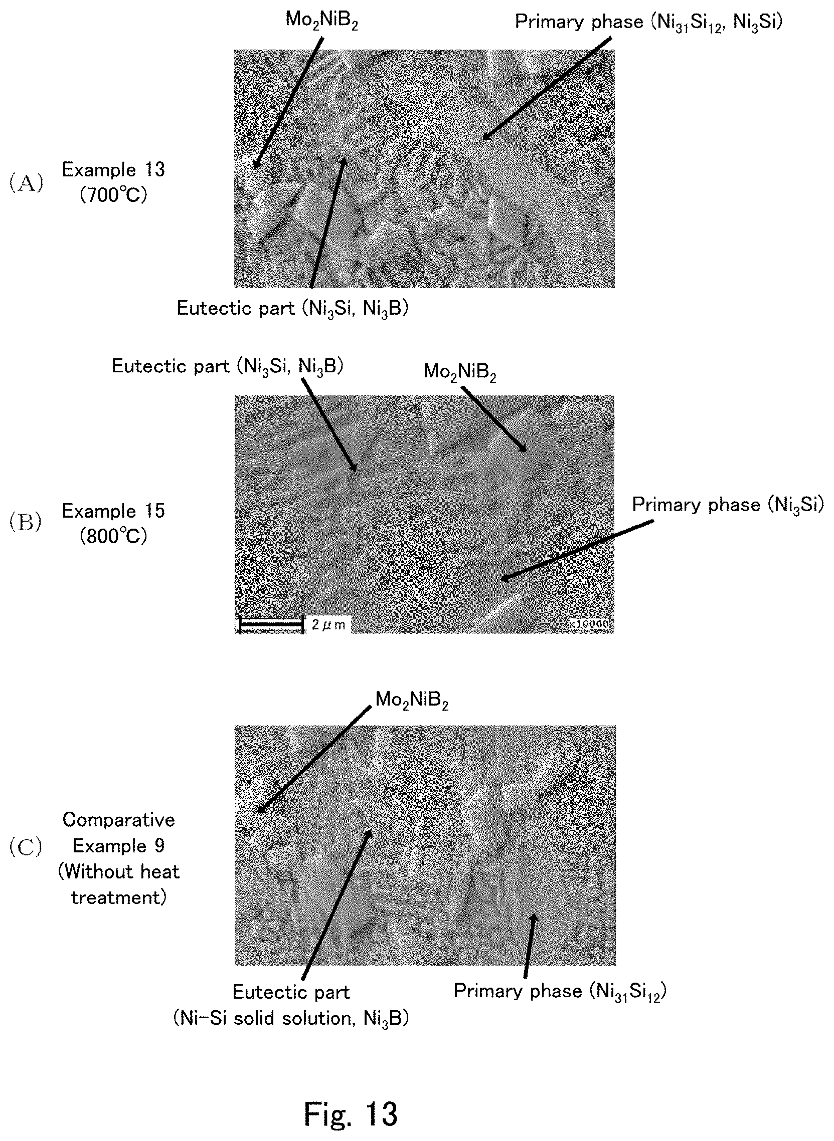
D00014

P00899

XML
uspto.report is an independent third-party trademark research tool that is not affiliated, endorsed, or sponsored by the United States Patent and Trademark Office (USPTO) or any other governmental organization. The information provided by uspto.report is based on publicly available data at the time of writing and is intended for informational purposes only.
While we strive to provide accurate and up-to-date information, we do not guarantee the accuracy, completeness, reliability, or suitability of the information displayed on this site. The use of this site is at your own risk. Any reliance you place on such information is therefore strictly at your own risk.
All official trademark data, including owner information, should be verified by visiting the official USPTO website at www.uspto.gov. This site is not intended to replace professional legal advice and should not be used as a substitute for consulting with a legal professional who is knowledgeable about trademark law.