Wheel End Surface Detection And Correction Device
XUE; Bowen ; et al.
U.S. patent application number 16/508205 was filed with the patent office on 2020-05-14 for wheel end surface detection and correction device. This patent application is currently assigned to CITIC Dicastal CO., LTD.. The applicant listed for this patent is CITIC Dicastal CO., LTD.. Invention is credited to Lei BAO, Baojun CUI, Jiandong GUO, Bowen XUE.
| Application Number | 20200147663 16/508205 |
| Document ID | / |
| Family ID | 64994827 |
| Filed Date | 2020-05-14 |


| United States Patent Application | 20200147663 |
| Kind Code | A1 |
| XUE; Bowen ; et al. | May 14, 2020 |
WHEEL END SURFACE DETECTION AND CORRECTION DEVICE
Abstract
A wheel end surface detection and correction device includes a rack, a detection system, a customized cylinder and a correction system.
| Inventors: | XUE; Bowen; (Qinhuangdao, CN) ; CUI; Baojun; (Qinhuangdao, CN) ; BAO; Lei; (Qinhuangdao, CN) ; GUO; Jiandong; (Qinhuangdao, CN) | ||||||||||
| Applicant: |
|
||||||||||
|---|---|---|---|---|---|---|---|---|---|---|---|
| Assignee: | CITIC Dicastal CO., LTD. Qinhuangdao CN |
||||||||||
| Family ID: | 64994827 | ||||||||||
| Appl. No.: | 16/508205 | ||||||||||
| Filed: | July 10, 2019 |
| Current U.S. Class: | 1/1 |
| Current CPC Class: | B21D 53/30 20130101; B21C 51/00 20130101; B21D 3/00 20130101; B21D 3/14 20130101 |
| International Class: | B21D 3/00 20060101 B21D003/00; B21D 53/30 20060101 B21D053/30; B21C 51/00 20060101 B21C051/00 |
Foreign Application Data
| Date | Code | Application Number |
|---|---|---|
| Nov 8, 2018 | CN | 201811321725.5 |
Claims
1. A wheel end surface detection and correction device, comprising a rack, first cylinders, first guide columns, first guide sleeves, a fixed plate, a first lifting frame, first guide rails, second guide rails, a first servo electric cylinder, a translational frame, third guide rails, a second lifting frame, a dial indicator, a supporting plate, an expansion core, an expansion sleeve, a reference plate, a cylinder rod, a piston, a cylinder body, a left copying pressing block, a left pressing rod, a rotating ring, a left guide sleeve, a movable plate, a servo motor, servo electric push rods, a lifting plate, second guide columns, second guide sleeves, a left servo electric cylinder, a second cylinder, a right servo electric cylinder, a right guide sleeve, a right pressing rod, a right copying pressing block and a second servo electric cylinder, wherein the fixed plate is fixed on the rack; the four first guide sleeves are fixed on the fixed plate; the four first guide columns matched with the first guide sleeves are fixed below the first lifting frame; the two first cylinders are also fixed on the fixed plate, and the output ends of the two first cylinders are hinged with the bottom of the first lifting frame; two sides of the first lifting frame are connected with the rack through the first guide rails; the front and rear ends of the supporting plate are fixed on the rack; a detection system is that: the bottom end of the translational frame is mounted above the bottom of the first lifting frame through the second guide rails; the second lifting frame is mounted on the side surface of the translational frame through the third guide rails; the first servo electric cylinder is fixed on a bottom plate of the translational frame, and the output end of the first servo electric cylinder is connected with the second lifting frame; the dial indicator is mounted on the second lifting frame; the second servo electric cylinder is fixed above the bottom of the first lifting frame, and the output end of the second servo electric cylinder is connected with the translational frame; a customized cylinder is that: the reference plate is fixed below the cylinder body; the piston is matched with an inner hole of the cylinder body; the cylinder rod is connected with the piston; the expansion sleeve is fixed below the reference plate; the expansion core is fixed at the top end of the cylinder rod; the outer side of the expansion core is matched with the inner side of the expansion sleeve; the top end of the cylinder body is mounted below the movable plate through the rotating ring; the servo motor is fixed above the movable plate, and the output end of the servo motor is connected with the top end of the cylinder body; the upper ends of the three servo electric push rods are hinged with the lower end of the lifting plate, and the lower ends are hinged with the top end of the movable plate; the three servo electric push rods are uniformly distributed between the movable plate and the lifting plate; the four second guide columns are fixed above the lifting plate; the four second guide sleeves matched with the four second guide columns are fixed at the top end of the rack; the second cylinder is also fixed at the top end of the rack, and the output end of the second cylinder is hinged with the top end of the lifting plate; and a correction system is that: the left servo electric cylinder is fixed on the left side of the top end of the rack; the left guide sleeve is fixed below the left servo electric cylinder and is matched with the left pressing rod; the top end of the left pressing rod is connected with the output end of the left servo electric cylinder, and the left copying pressing block is fixed at the left end of the left pressing rod; the right servo electric cylinder is fixed on the right side of the top end of the rack; the right guide sleeve is fixed below the right servo electric cylinder and is matched with the right pressing rod; the top end of the right pressing rod is connected with the output end of the right servo electric cylinder; and the right copying pressing block is fixed at the lower end of the right pressing rod.
Description
CROSS-REFERENCE TO RELATED APPLICATION
[0001] The present application claims benefit of Chinese Patent Application No. 201811321725.5, filed on Nov. 8, 2018, the contents of which are hereby incorporated by reference in their entirety.
BACKGROUND
[0002] In a machining process of aluminum alloy wheels, a machined wheel end surface is often unqualified in runout due to an end surface deformation and a clamping deformation of a blank, which will cause a wheel to vibrate during driving and affect the driving safety and comfort. Therefore, there is a need for automated equipment that performs online detection on the end surface runout of the wheel and corrects unqualified workpieces.
SUMMARY
[0003] The present disclosure relates to a detection and correction device, and more particularly relates to a wheel end surface detection and correction device.
[0004] The present disclosure aims to provide a wheel end surface detection and correction device. The device may detect the end surface runout of a wheel on line and correct the wheel end surface on line when used.
[0005] In order to achieve the aforementioned objective, the technical solution of the present disclosure is as follows: A wheel end surface detection and correction device, consisting of a rack, first cylinders, first guide columns, first guide sleeves, a fixed plate, a first lifting frame, first guide rails, second guide rails, a first servo electric cylinder, a translational frame, third guide rails, a second lifting frame, a dial indicator, a supporting plate, an expansion core, an expansion sleeve, a reference plate, a cylinder rod, a piston, a cylinder body, a left copying pressing block, a left pressing rod, a rotating ring, a left guide sleeve, a movable plate, a servo motor, servo electric push rods, a lifting plate, second guide columns, second guide sleeves, a left servo electric cylinder, a second cylinder, a right servo electric cylinder, a right guide sleeve, a right pressing rod, a right copying pressing block and a second servo electric cylinder, the fixed plate is fixed on the rack; the four first guide sleeves are fixed on the fixed plate; the four first guide columns matched with the first guide sleeves are fixed below the first lifting frame; the two first cylinders are also fixed on the fixed plate, and the output ends of the two first cylinders are hinged with the bottom of the first lifting frame; two sides of the first lifting frame are connected with the rack through the first guide rails; the front and rear ends of the supporting plate are fixed on the rack.
[0006] A detection system is that: the bottom end of the translational frame is mounted above the bottom of the first lifting frame through the second guide rails; the second lifting frame is mounted on the side surface of the translational frame through the third guide rails; the first servo electric cylinder is fixed on a bottom plate of the translational frame, and the output end of the first servo electric cylinder is connected with the second lifting frame; the dial indicator is mounted on the second lifting frame; the second servo electric cylinder is fixed above the bottom of the first lifting frame, and the output end of the second servo electric cylinder is connected with the translational frame.
[0007] A customized cylinder is that: the reference plate is fixed below the cylinder body; the piston is matched with an inner hole of the cylinder body; the cylinder rod is connected with the piston.
[0008] The expansion sleeve is fixed below the reference plate; the expansion core is fixed at the top end of the cylinder rod; the outer side of the expansion core is matched with the inner side of the expansion sleeve; the top end of the cylinder body is mounted below the movable plate through the rotating ring; the servo motor is fixed above the movable plate, and the output end of the servo motor is connected with the top end of the cylinder body; the upper ends of the three servo electric push rods are hinged with the lower end of the lifting plate, and the lower ends are hinged with the top end of the movable plate; the three servo electric push rods are uniformly distributed between the movable plate and the lifting plate; the four second guide columns are fixed above the lifting plate; the four second guide sleeves matched with the four second guide columns are fixed at the top end of the rack; the second cylinder is also fixed at the top end of the rack, and the output end of the second cylinder is hinged with the top end of the lifting plate.
[0009] A correction system is that: the left servo electric cylinder is fixed on the left side of the top end of the rack; the left guide sleeve is fixed below the left servo electric cylinder and is matched with the left pressing rod; the top end of the left pressing rod is connected with the output end of the left servo electric cylinder, and the left copying pressing block is fixed at the left end of the left pressing rod; the right servo electric cylinder is fixed on the right side of the top end of the rack; the right guide sleeve is fixed below the right servo electric cylinder and is matched with the right pressing rod; the top end of the right pressing rod is connected with the output end of the right servo electric cylinder; and the right copying pressing block is fixed at the lower end of the right pressing rod.
[0010] In a working process, firstly, a stopper initially locates a wheel in the center; a second cylinder enables an expansion sleeve to move down through second guide columns and be matched with a wheel center hole; three servo electric push rods adjust a posture of a reference plate to cause the reference plate to be flatly fitted to a wheel flange surface; a cylinder rod pulls an expansion core to tighten the wheel; the second cylinder lifts the wheel, and a servo motor enables the wheel to rotate; a second servo electric cylinder enables a dial indicator to be located below the end surface of a wheel rim of the wheel through second guide rails; a first servo electric cylinder enables the dial indicator to be in contact with the wheel end surface through third guide rails; at the moment, the end surface runout of the wheel may be detected; after the detection is completed, first cylinders enable a first lifting frame to move down via first guide columns; meanwhile, the second cylinder enables the wheel end surface to be flatly fitted to a supporting plate; a right servo motor enables a right copying pressing block to be flatly fitted to the upper end surface of one side of the wheel through a right pressing rod, but no force is applied; and a left servo motor enables a left copying pressing block to over press the other side of the wheel through a left pressing rod to cause the lower end surface to move down, so as to achieve the aim of correcting the end surface.
[0011] The present disclosure may detect the end surface runout of the wheel on line and correct the wheel end surface on line when used, and has the characteristics of high automation degree, advanced process, high generality, safe and stable performance and the like.
BRIEF DESCRIPTION OF THE DRAWINGS
[0012] FIG. 1 is a front view of a wheel end surface detection and correction device of the present disclosure;
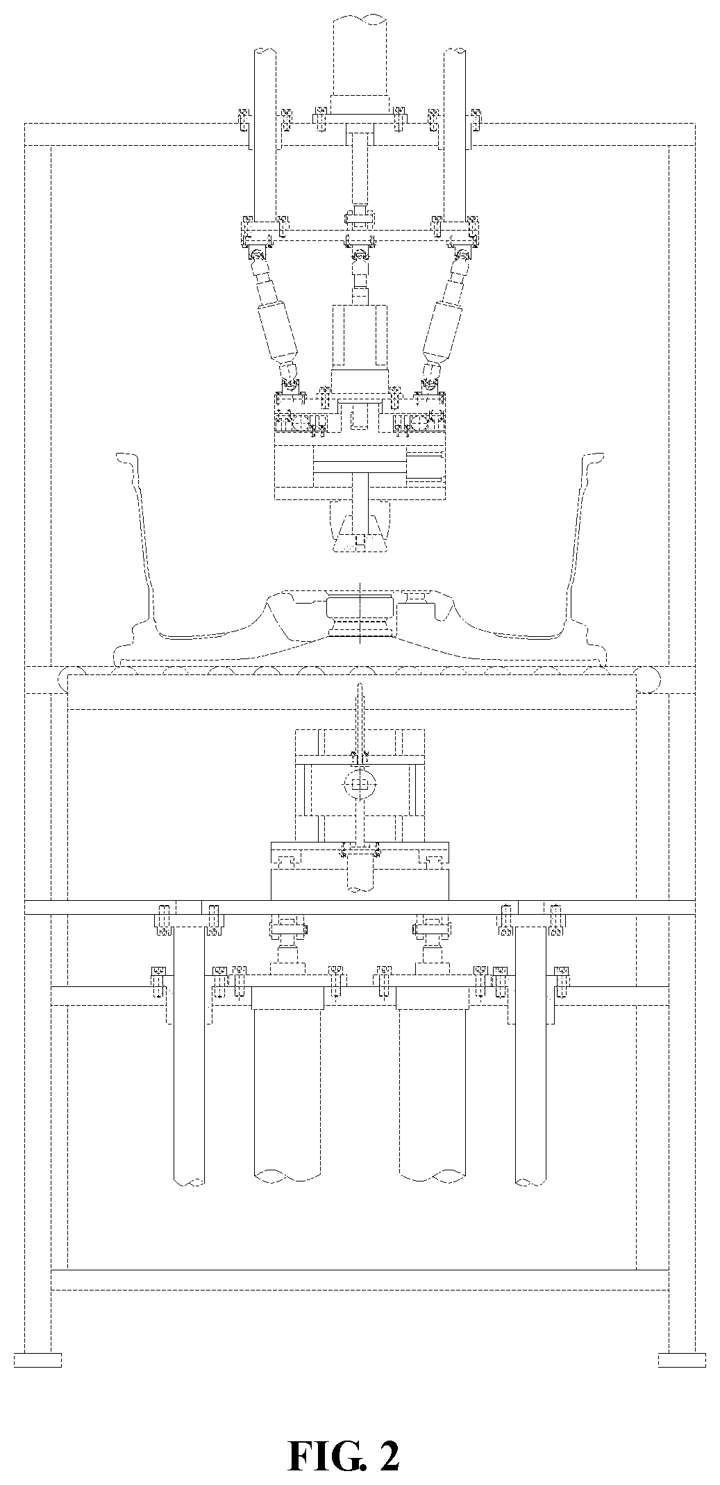
[0013] FIG. 2 is a left view of a wheel end surface detection and correction device of the present disclosure; and
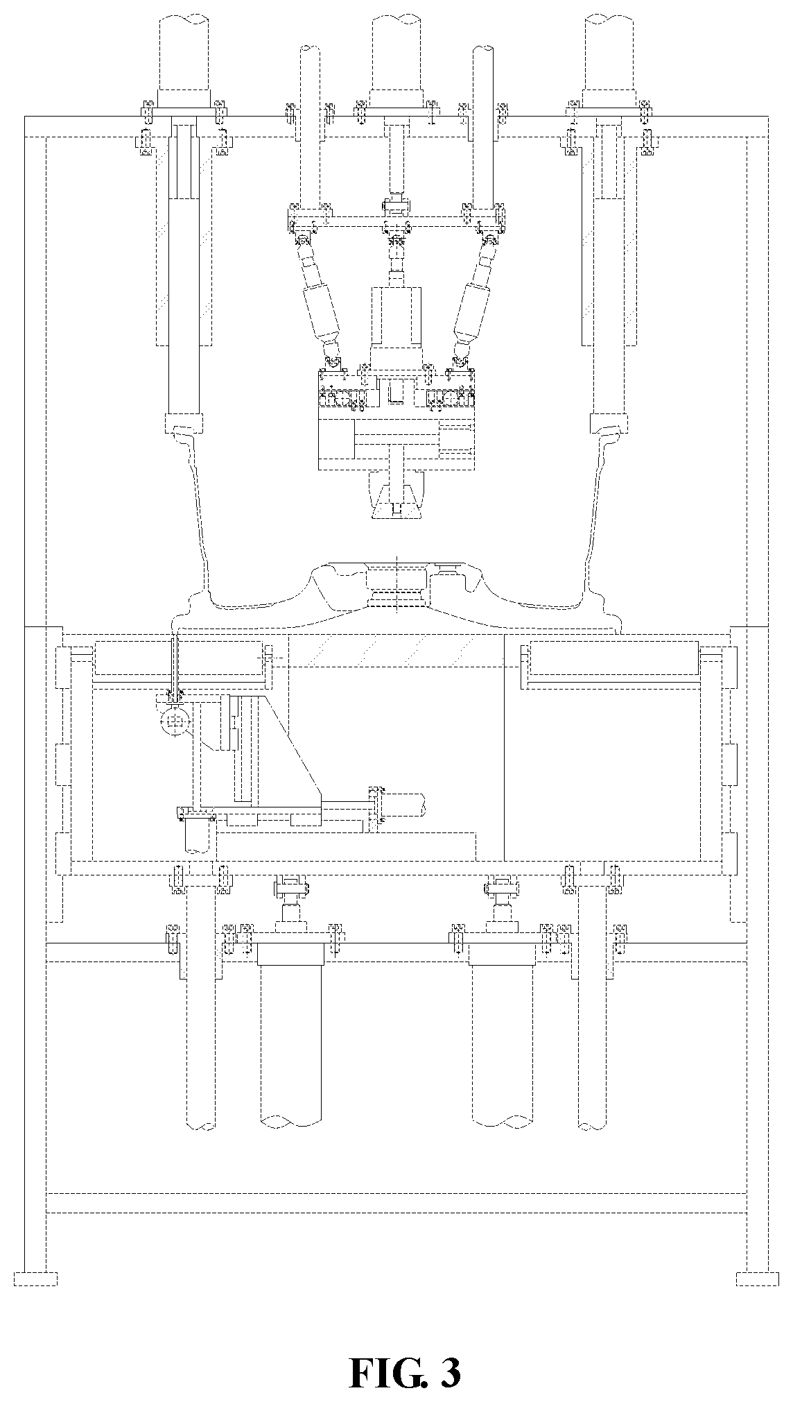
[0014] FIG. 3 is a front view of a wheel end surface detection and correction device of the present disclosure during working.
LIST OF REFERENCE SYMBOLS
[0015] 1: rack; 2: first cylinder; 3: first guide column; 4: first guide sleeve; 5: fixed plate; 6: first lifting frame; 7: first guide rail; 8: second guide rail; 9: first servo electric cylinder; 10: translational frame; 11: third guide rail; 12: second lifting frame; 13: dial indicator; 14: supporting plate; 15: expansion core; 16: expansion sleeve; 17: reference plate; 18: cylinder rod; 19: piston; 20: cylinder body; 21: left copying pressing block; 22: left pressing rod; 23: rotating ring; 24: left guide sleeve; 25: movable plate; 26: servo motor; 27: servo electric push rod; 28: lifting plate; 29: second guide column; 30: second guide sleeve; 31: left servo electric cylinder; 32: second cylinder; 33: right servo electric cylinder; 34: right guide sleeve; 35: right pressing rod; 36: right copying pressing block; and 27: second servo electric cylinder.
DETAILED DESCRIPTION
[0016] Details and working conditions of a specific device provided according to the present disclosure are described below in combination with accompanying drawings.
[0017] As illustrated in FIGS. 1-3, the device can include a rack 1, first cylinders 2, first guide columns 3, first guide sleeves 4, a fixed plate 5, a first lifting frame 6, first guide rails 7, second guide rails 8, a first servo electric cylinder 9, a translational frame 10, third guide rails 11, a second lifting frame 12, a dial indicator 13, a supporting plate 14, an expansion core 15, an expansion sleeve 16, a reference plate 17, a cylinder rod 18, a piston 19, a cylinder body 20, a left copying pressing block 21, a left pressing rod 22, a rotating ring 23, a left guide sleeve 24, a movable plate 25, a servo motor 26, servo electric push rods 27, a lifting plate 28, second guide columns 29, second guide sleeves 30, a left servo electric cylinder 31, a second cylinder 32, a right servo electric cylinder 33, a right guide sleeve 34, a right pressing rod 35, a right copying pressing block 36 and a second servo electric cylinder 37, the fixed plate 5 is fixed on the rack 1; the four first guide sleeves 4 are fixed on the fixed plate 5; the four first guide columns 3 matched with the first guide sleeves 4 are fixed below the first lifting frame 6; the two first cylinders 2 are also fixed on the fixed plate 5, and the output ends of the two first cylinders 2 are hinged with the bottom of the first lifting frame 6; two sides of the first lifting frame 6 are connected with the rack 1 through the first guide rails 7; the front and rear ends of the supporting plate 14 are fixed on the rack 1.
[0018] A detection system is that: the bottom end of the translational frame 10 is mounted above the bottom of the first lifting frame 6 through the second guide rails 8; the second lifting frame 12 is mounted on the side surface of the translational frame 10 through the third guide rails 11; the first servo electric cylinder 9 is fixed on a bottom plate of the translational frame 10, and the output end of the first servo electric cylinder 9 is connected with the second lifting frame 12; the dial indicator 13 is mounted on the second lifting frame 12; the second servo electric cylinder 37 is fixed above the bottom of the first lifting frame 6, and the output end of the second servo electric cylinder 37 is connected with the translational frame 10.
[0019] A customized cylinder is that: the reference plate 17 is fixed below the cylinder body 20; the piston 19 is matched with an inner hole of the cylinder body 20; the cylinder rod 18 is connected with the piston 19.
[0020] The expansion sleeve 16 is fixed below the reference plate 17; the expansion core 15 is fixed at the top end of the cylinder rod 18; the outer side of the expansion core 15 is matched with the inner side of the expansion sleeve 16; the top end of the cylinder body 20 is mounted below the movable plate 25 through the rotating ring 23; the servo motor 26 is fixed above the movable plate 25, and the output end of the servo motor 26 is connected with the top end of the cylinder body 20; the upper ends of the three servo electric push rods 27 are hinged with the lower end of the lifting plate 28, and the lower ends are hinged with the top end of the movable plate 25; the three servo electric push rods 27 are uniformly distributed between the movable plate 25 and the lifting plate 28; the four second guide columns 29 are fixed above the lifting plate 28; the four second guide sleeves 30 matched with the four second guide columns 29 are fixed at the top end of the rack 1; the second cylinder 32 is also fixed at the top end of the rack 1, and the output end of the second cylinder 32 is hinged with the top end of the lifting plate 28.
[0021] A correction system is that: the left servo electric cylinder 31 is fixed on the left side of the top end of the rack 1; the left guide sleeve 24 is fixed below the left servo electric cylinder 31 and is matched with the left pressing rod 22; the top end of the left pressing rod 22 is connected with the output end of the left servo electric cylinder 31, and the left copying pressing block 21 is fixed at the left end of the left pressing rod 22; the right servo electric cylinder 33 is fixed on the right side of the top end of the rack 1; the right guide sleeve 34 is fixed below the right servo electric cylinder 33 and is matched with the right pressing rod 35; the top end of the right pressing rod 35 is connected with the output end of the right servo electric cylinder 33; and the right copying pressing block 36 is fixed at the lower end of the right pressing rod 35.
[0022] In a working process, firstly, a stopper initially locates a wheel in the center; a second cylinder 32 enables an expansion sleeve 16 to move down through second guide columns 29 and be matched with a wheel center hole; three servo electric push rods 27 adjust a posture of a reference plate 17 to cause the reference plate 17 to be flatly fitted to a wheel flange surface; a cylinder rod 18 pulls an expansion core 15 to tighten the wheel; the second cylinder 32 lifts the wheel, and a servo motor 26 enables the wheel to rotate; a second servo electric cylinder 37 enables a dial indicator 13 to be located below the end surface of a wheel rim of the wheel through second guide rails 8; a first servo electric cylinder 9 enables the dial indicator 13 to be in contact with the wheel end surface through third guide rails 11; at the moment, the end surface runout of the wheel may be detected; after the detection is completed, first cylinders 2 enable a first lifting frame 6 to move down via first guide columns 3; meanwhile, the second cylinder 32 enables the wheel end surface to be flatly fitted to a supporting plate 14; a right servo motor 33 enables a right copying pressing block 36 to be flatly fitted to the upper end surface of one side of the wheel through a right pressing rod 35, but no force is applied; and a left servo motor 31 enables a left copying pressing block 21 to over press the other side of the wheel through a left pressing rod 22 to cause the lower end surface to move down, so as to achieve the aim of correcting the end surface.
* * * * *
D00000
D00001
D00002
D00003
XML
uspto.report is an independent third-party trademark research tool that is not affiliated, endorsed, or sponsored by the United States Patent and Trademark Office (USPTO) or any other governmental organization. The information provided by uspto.report is based on publicly available data at the time of writing and is intended for informational purposes only.
While we strive to provide accurate and up-to-date information, we do not guarantee the accuracy, completeness, reliability, or suitability of the information displayed on this site. The use of this site is at your own risk. Any reliance you place on such information is therefore strictly at your own risk.
All official trademark data, including owner information, should be verified by visiting the official USPTO website at www.uspto.gov. This site is not intended to replace professional legal advice and should not be used as a substitute for consulting with a legal professional who is knowledgeable about trademark law.