System And Method For Connecting Magnetic Building Tiles
Romanoff; Marc ; et al.
U.S. patent application number 16/681407 was filed with the patent office on 2020-05-14 for system and method for connecting magnetic building tiles. The applicant listed for this patent is Genius Gems, LLC. Invention is credited to Andrew Carter, Marc Romanoff, Jenna Stuiso.
| Application Number | 20200147508 16/681407 |
| Document ID | / |
| Family ID | 70551458 |
| Filed Date | 2020-05-14 |


View All Diagrams
| United States Patent Application | 20200147508 |
| Kind Code | A1 |
| Romanoff; Marc ; et al. | May 14, 2020 |
SYSTEM AND METHOD FOR CONNECTING MAGNETIC BUILDING TILES
Abstract
A base member configured for use with a windowed magnetic tile, the base member including a tile portion having three or more outer edges configured with respective protrusions for fitting engagement with respective notches on corresponding three or more inner edges of the windowed magnetic tile; a first projection extending outwardly from a first surface of the tile portion formed by the three or more outer edges; and a first opening disposed on the first projection.
| Inventors: | Romanoff; Marc; (Millburn, NJ) ; Carter; Andrew; (Millburn, NJ) ; Stuiso; Jenna; (Millburn, NJ) | ||||||||||
| Applicant: |
|
||||||||||
|---|---|---|---|---|---|---|---|---|---|---|---|
| Family ID: | 70551458 | ||||||||||
| Appl. No.: | 16/681407 | ||||||||||
| Filed: | November 12, 2019 |
Related U.S. Patent Documents
| Application Number | Filing Date | Patent Number | ||
|---|---|---|---|---|
| 62758775 | Nov 12, 2018 | |||
| Current U.S. Class: | 1/1 |
| Current CPC Class: | A63H 33/108 20130101; A63H 33/086 20130101; A63H 33/046 20130101 |
| International Class: | A63H 33/04 20060101 A63H033/04; A63H 33/08 20060101 A63H033/08; A63H 33/10 20060101 A63H033/10 |
Claims
1. A base member configured for use with a windowed magnetic tile, the base member comprising: a tile portion having three or more outer edges configured with respective protrusions for fitting engagement with respective notches on corresponding three or more inner edges of the windowed magnetic tile; a first projection extending outwardly from a first surface of the tile portion formed by the three or more outer edges; and a first opening disposed on the first projection.
2. The base member of claim 1, further comprising: a second projection extending outwardly from a second surface of the tile portion formed by the three or more outer edges; and a second opening disposed on the second projection, wherein the second surface is on an opposite side from the first surface of the tile portion.
3. The base member of claim 1, further comprising a connector inserted into the first opening.
4. The base member of claim 3, wherein the connector comprises a plurality of ends that are insertable to the first opening.
5. The base member of claim 4, wherein the plurality of ends are at a right angle from one another on a common plane.
6. The base member of claim 5, wherein the connector comprises four ends to form a cross shape.
7. The base member of claim 4, wherein the plurality of ends are at a 120 degree angle from one another on a common plane.
8. The base member of claim 3, wherein the connector is a bearing that comprises a disc-shaped portion.
9. The base member of claim 8, further comprising a wheel having a third opening through which the connector is inserted into the first opening of the base member.
10. The base member of claim 1, wherein the tile portion is a square-shaped tile portion for fitting to a square-shaped opening in the windowed magnetic tile.
Description
CROSS-REFERENCE TO RELATED APPLICATION
[0001] The present application claims the benefit of and priority to U.S. Provisional Patent Application No. 62/758,775, filed on Nov. 12, 2018, the entire contents of which are incorporated by reference herein.
FIELD OF THE INVENTION
[0002] The invention relates to the field of building toys and, more specifically, to a system and method for connecting magnetic building tiles.
BACKGROUND OF THE INVENTION
[0003] Magnetic tiles are a popular building toy for children of all ages. As is known, these tiles are available in various shapes and sizes and generally have small magnets positioned around their periphery that allow them to be interconnected with other magnetic tiles. Magnetic tiles are widely used to foster the development of science, technology, engineering and mathematics (STEM) skills in children. For example, they can be used to teach geometry, as well as design and construction techniques.
[0004] However, there are limitations on the types of structures that can be built using magnetic tiles due, in large part, to their magnetic connection systems. Even high-quality magnetic tiles, which have relatively strong magnets, cannot support significant weight and are easily separated during play. As such, users, particularly younger children, may find building with magnetic tiles frustrating. Moreover, even older children and adults may wish to build structures with magnetic tiles that have increased structural rigidity.
[0005] As such, there is a need for a new system and method for connecting magnetic building tiles. Such a system and method would be particularly useful if it provided increased structural rigidity to projects constructed using magnetic building tiles.
SUMMARY OF THE INVENTION
[0006] The invention relates to a system and method for connecting magnetic building tiles. The system may include: magnetic building tiles that have open center portions (commonly referred to as window tiles), base members that snap into the window tiles, and a variety of connector elements that connect the tiles to one another. The system may further include bearing and wheels for constructing vehicles and other rotating structures.
BRIEF DESCRIPTION OF THE DRAWINGS
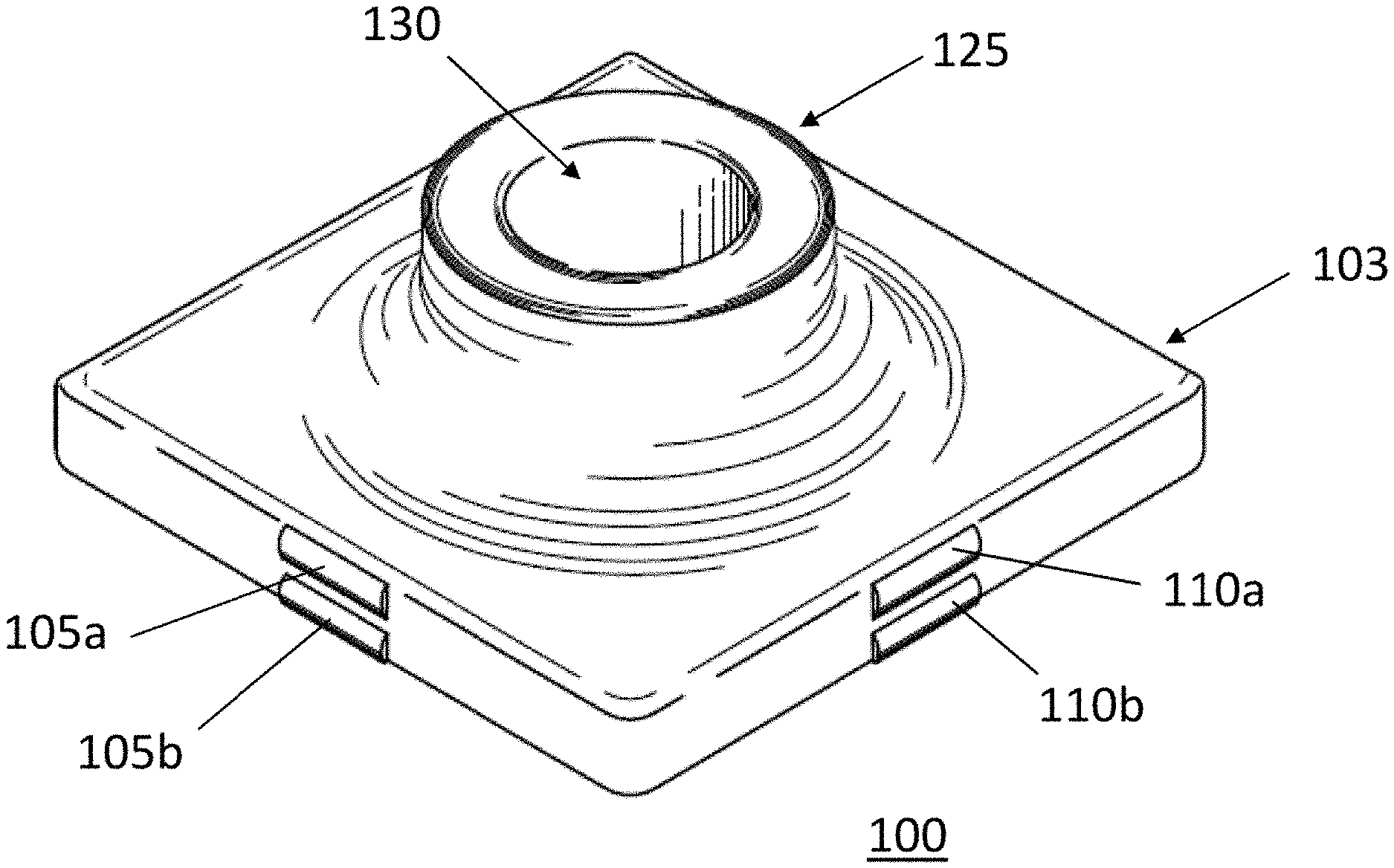
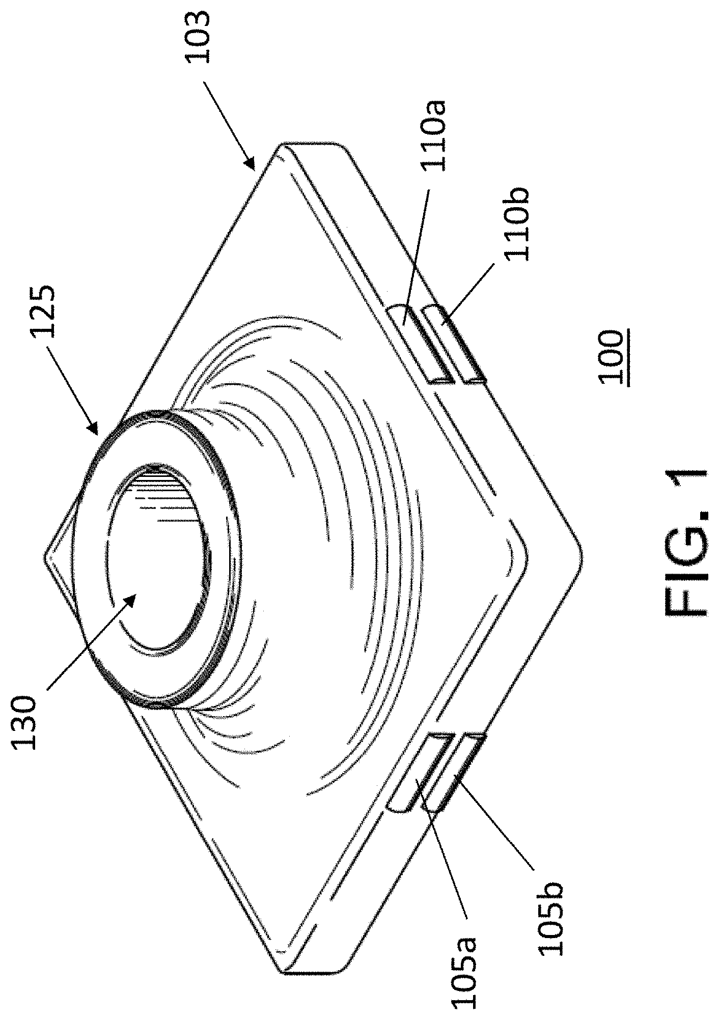
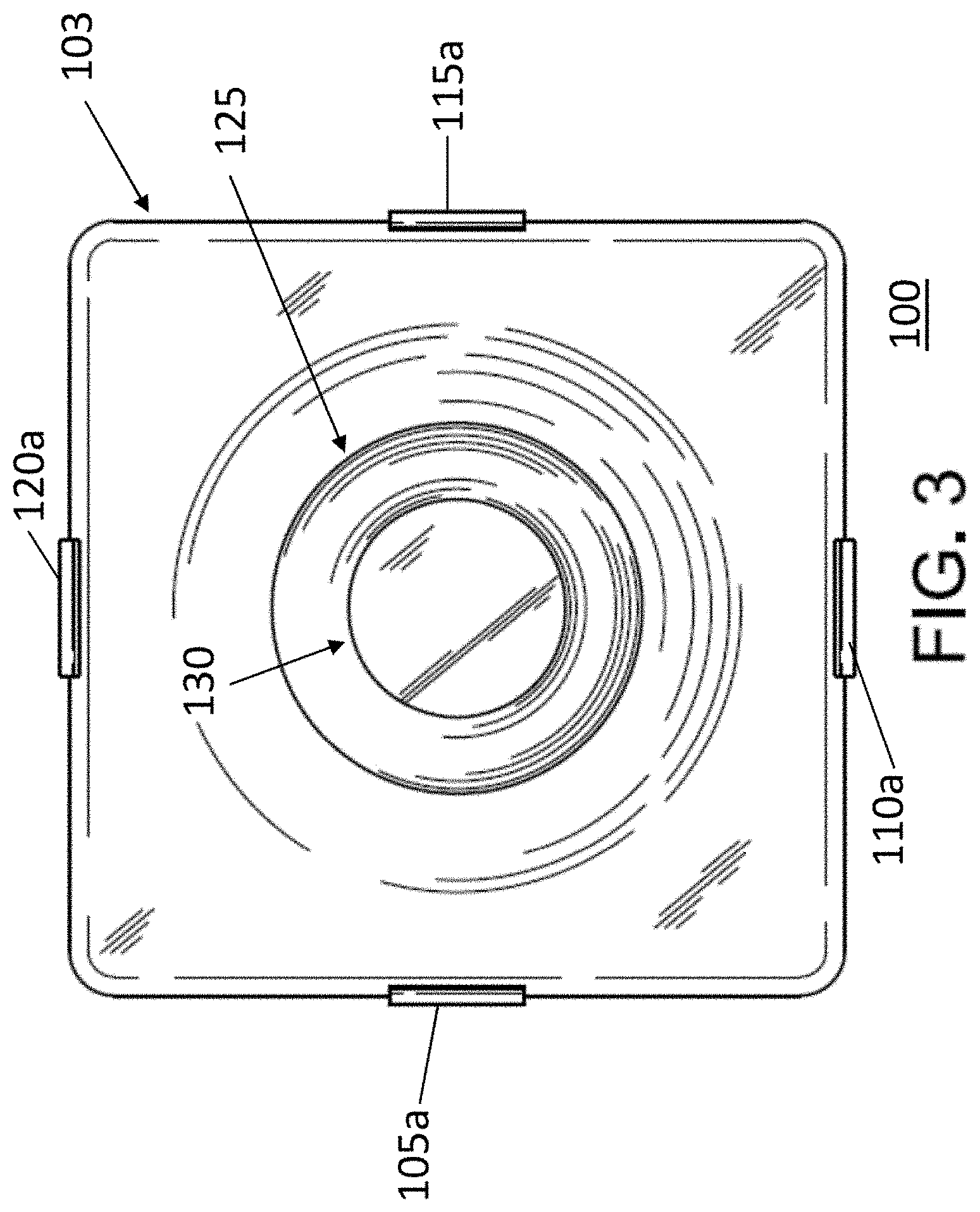
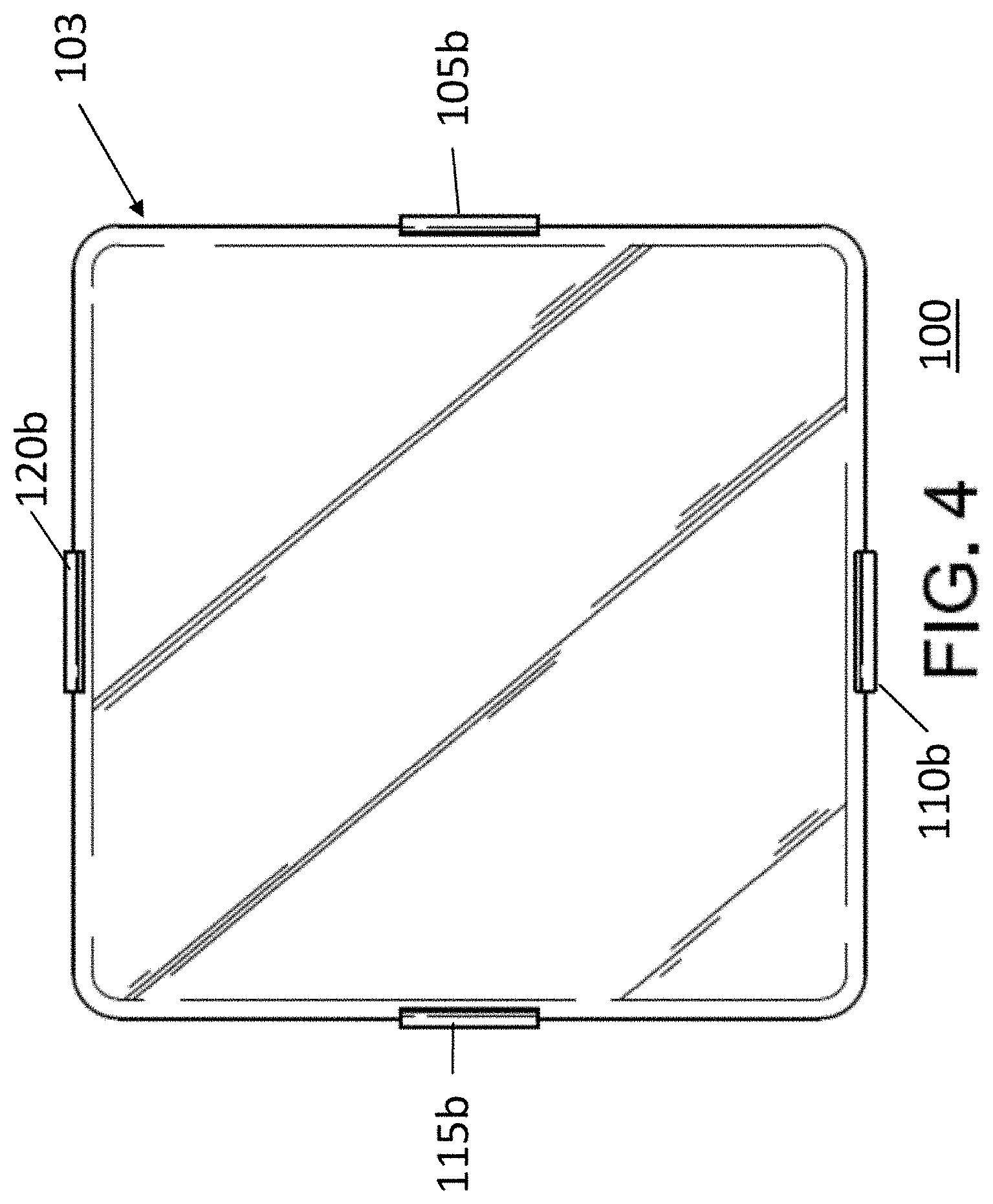
[0007] FIGS. 1-4 are illustrations of an embodiment of a base member for use with the disclosed system and method;
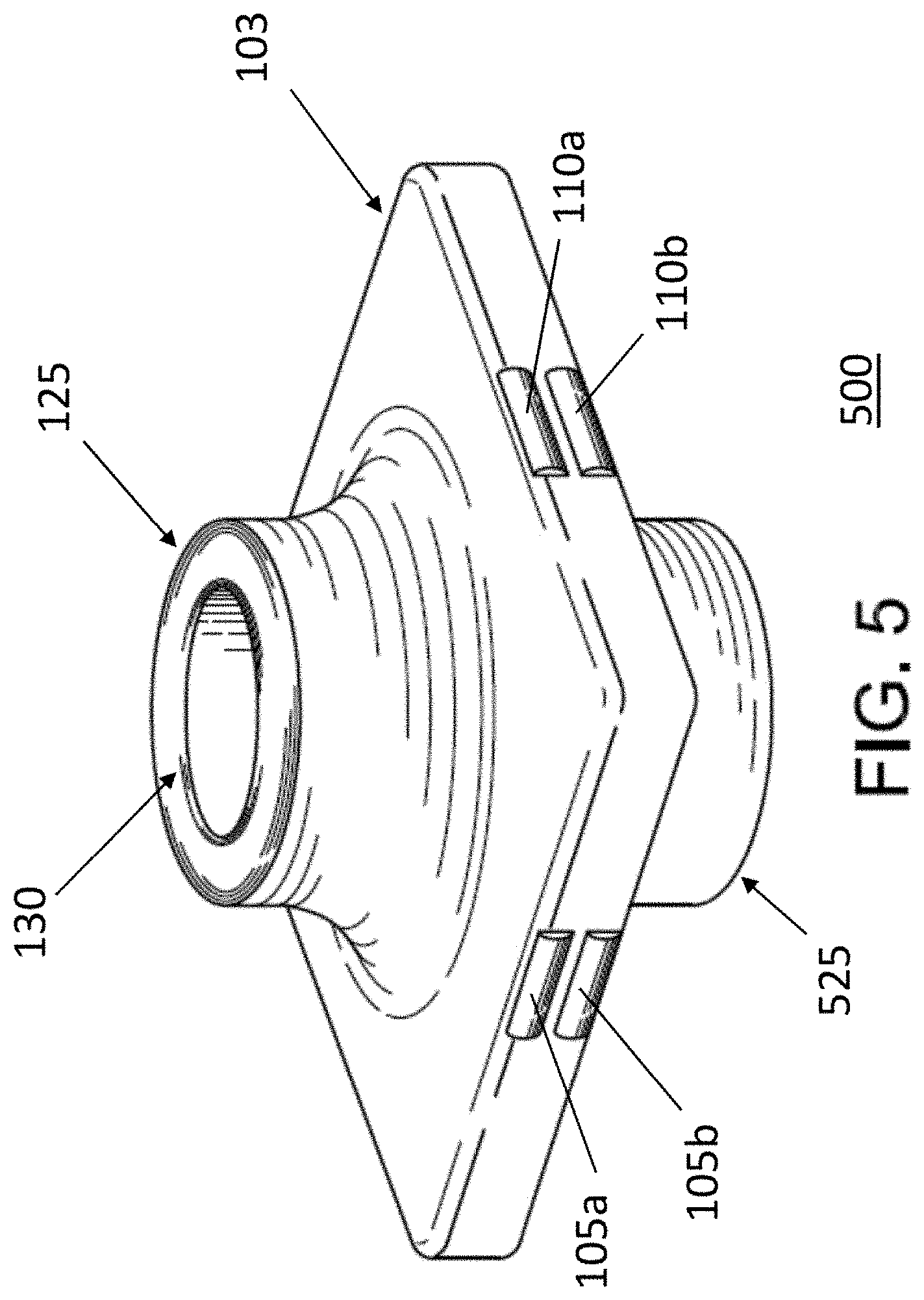
[0008] FIGS. 5-8 are illustrations of a second embodiment of a base member for use with the disclosed system and method;
[0009] FIG. 9A is a photograph of a prior art magnetic building set;
[0010] FIG. 9B is an illustration of a windowed magnetic tile for use with a base member according to an exemplary embodiment of the present invention;
[0011] FIG. 9C is a diagram showing a base member incorporated with the windowed magnetic tile of FIG. 9B according to an exemplary embodiment of the present invention;
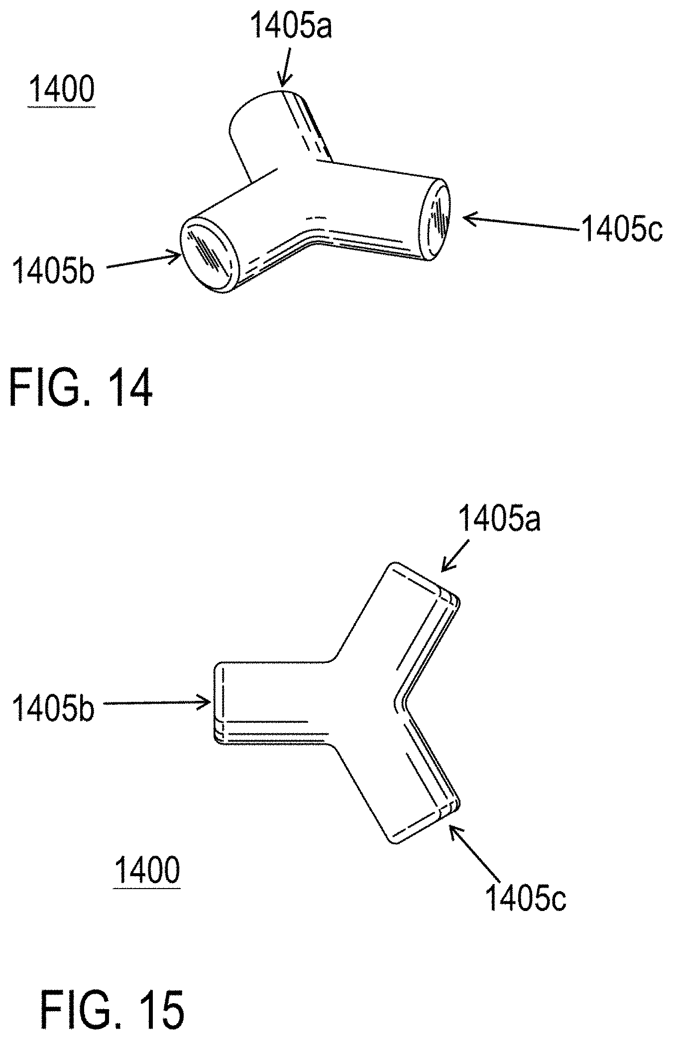
[0012] FIGS. 10-15 are illustrations of various embodiments of the connectors for use with the disclosed system and method;
[0013] FIGS. 16-17 are illustrations of a bearing for use with the disclosed system and method;
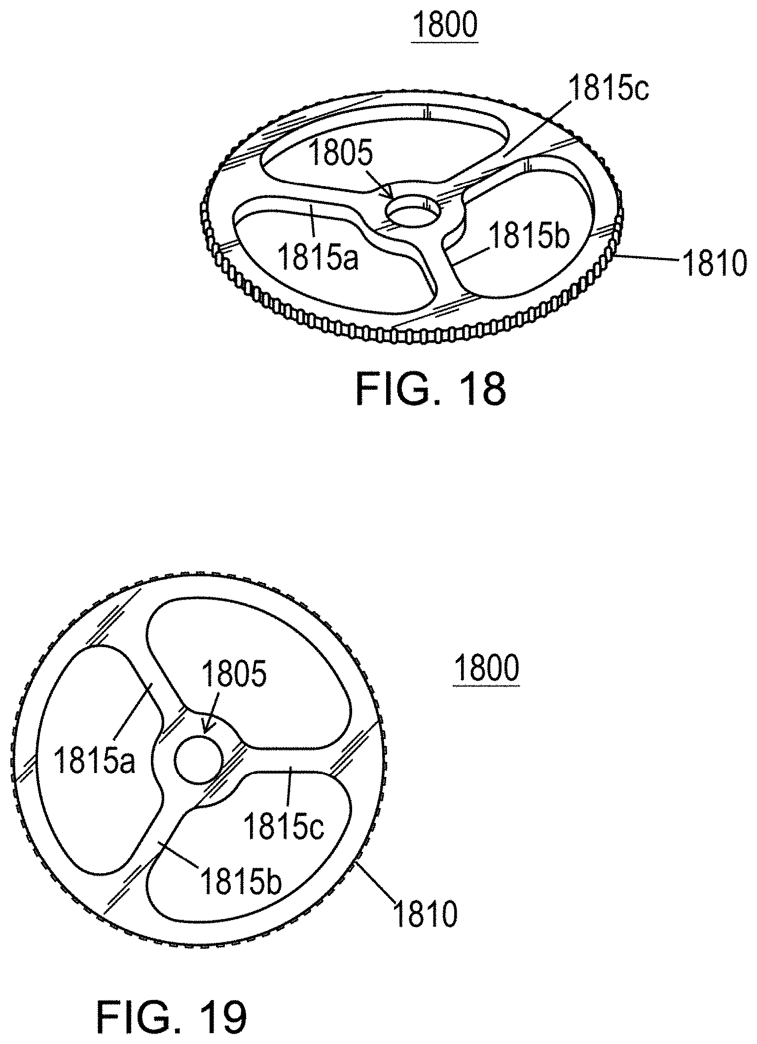
[0014] FIGS. 18-19 are illustrations of a wheel for use with the disclosed system and method;
[0015] FIGS. 20-22 are photographs demonstrating how the above base members and connectors can be used in accordance with the disclosed system and method;
[0016] FIGS. 23 and 24 are diagrams illustrating a connector for use with the base members of FIGS. 1-8 according to an exemplary embodiment of the present invention;
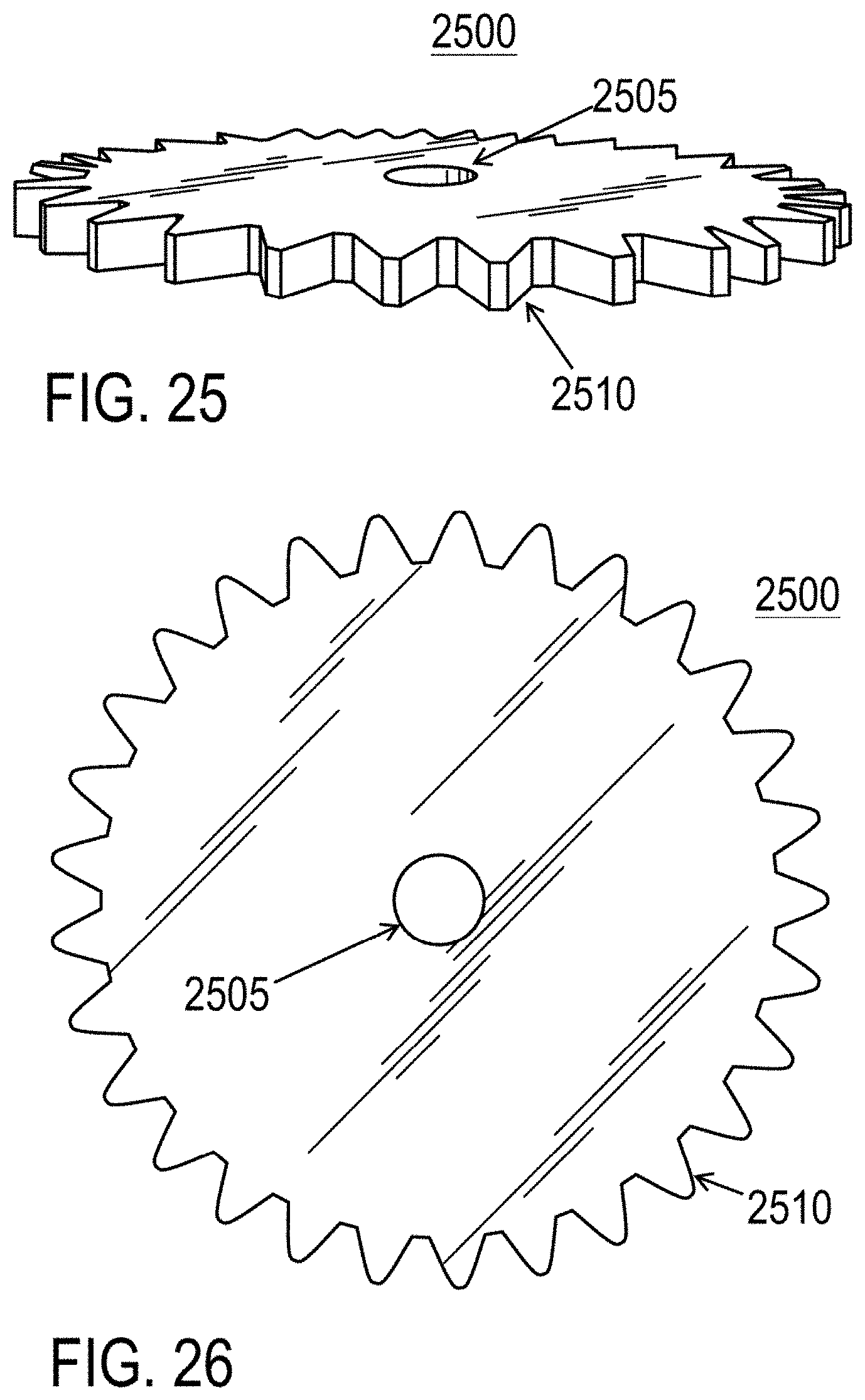
[0017] FIGS. 25 and 26 are diagrams illustrating a gear member for use with the base members of FIGS. 1-8 according to an exemplary embodiment of the present invention;
[0018] FIG. 27 is a diagram showing the gear member of FIGS. 25 and 26 being incorporated with a base member using a bearing of FIGS. 16 and 17 according to an exemplary embodiment of the present invention; and
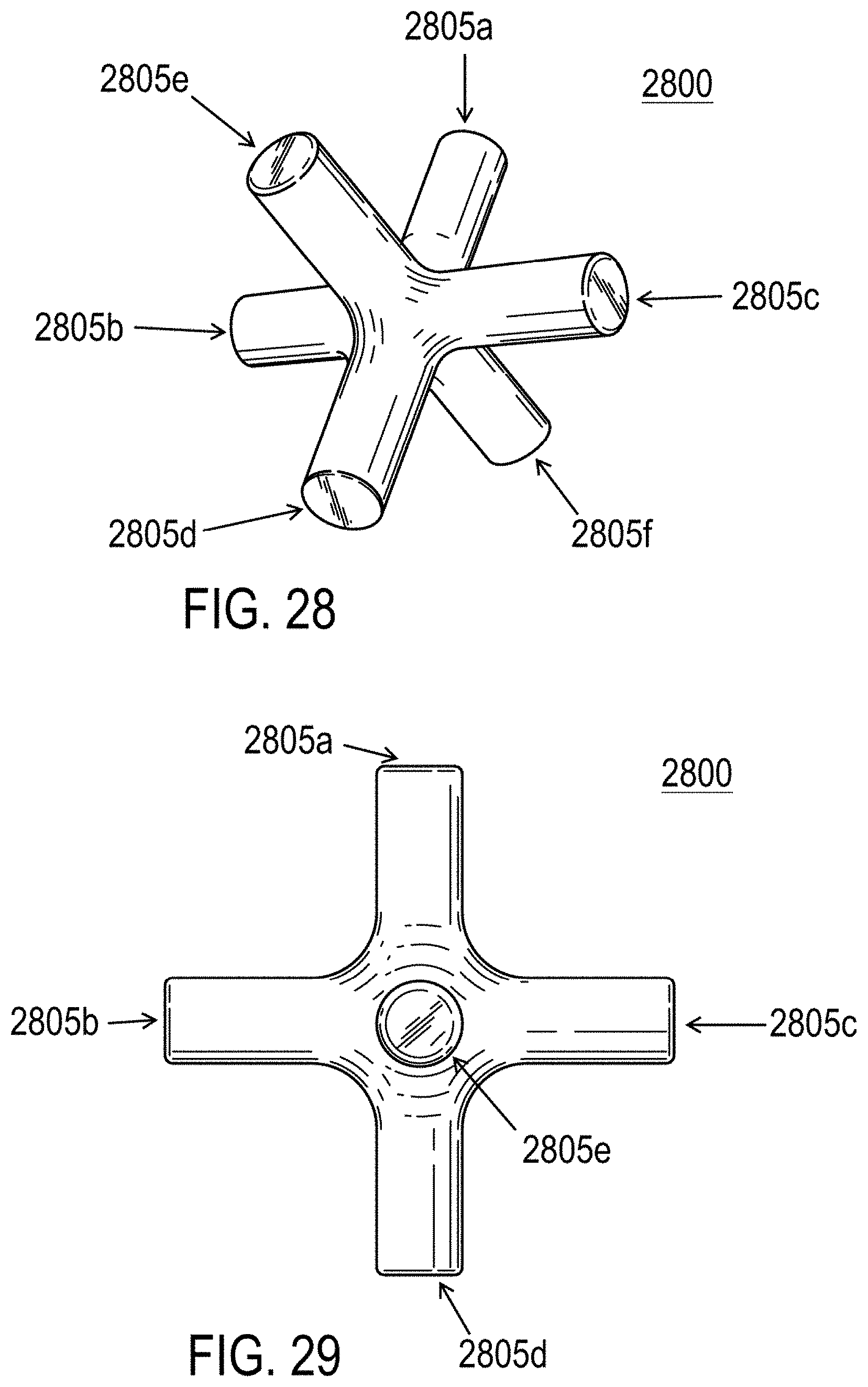
[0019] FIGS. 28 and 29 are diagrams illustrating a connector for use with the base members of FIGS. 1-8 according to an exemplary embodiment of the present invention.
DETAILED DESCRIPTION OF THE INVENTION
[0020] Embodiments of the present invention will now be described with reference to the above-identified Drawings. However, the Drawings and the description herein of the invention are not intended to limit the scope of the invention. It will be understood that various modifications of the present description of the invention are possible without departing from the spirit of the invention. Also, features described herein may be omitted, additional features may be included, and/or features described herein may be combined in a manner different from the specific combinations recited herein, all without departing from the spirit of the invention.
[0021] Shown in FIG. 9A is a known magnetic tile building set 900 sold under the PLAYMAGS.TM. brand. As can be seen in FIG. 9B, each tile in this particular set 900 is a window tile (905 and 910), i.e., it has a square opening 915 in its center. Letters, numbers, and other mathematic operators (e.g. "D" 920) can be snapped into the center portion of the tiles (e.g. 910). However, as discussed, such building systems rely solely upon the strength of the small magnets (e.g., 925, 930, 935, 940, 945, 950, 955, and 960) positioned around the perimeter of the tiles (generally two magnets on each side, e.g., 925, 930, 935, 940, 945, 950, 955, and 960) to maintain the connection between tiles.
[0022] Shown in FIGS. 1-4 is a base member 100 according to an exemplary embodiment of the present invention. FIG. 1 is a perspective view, FIG. 2 is a front view, FIG. 3 is a top view, and FIG. 4 is a bottom view of a base member 100 according to an exemplary embodiment of the present invention. As illustrated in FIG. 9C, the base member 100 is configured to snap into a magnetic window tile, such as square opening 915 of tile 905 shown in FIG. 9B. In this embodiment, as illustrated in FIGS. 1-4, the base member 100 includes a square tile portion 103 that is dimensioned to fit and that would be held in position in square opening 915 of tile 905 by elongated protrusions 105a, 105b, 110a, 110b, 115a, 115b, 120a, and 120b, two (2) of which are located on each of the four edges of the square tile portion 103 of the base member 100. According to an exemplary embodiment and as shown in FIGS. 1-4, the protrusions 105a, 105b, 110a, 110b, 115a, 115b, 120a, and 120b are positioned at the centers along the respective edges of the square tile portion 103 of base 100 and are dimensioned to fit with corresponding notches (e.g., 965 and 970 illustrated in FIG. 9B) in square opening 915 of tile 905 so that base member 100 is held in place while being removable from tile 905 without requiring excessive force. According to other embodiments, base member 100 may also have a tile portion corresponding to square tile portion 103 with a different shape--such as a triangle, pentagon, hexagon, octagon, and the like--for fitting in magnetic tiles having openings with such corresponding shapes.
[0023] As shown in FIGS. 1-3, base member 100 has a volcano-shaped projection 125 extending from one of its faces that, as discussed further below, is configured--e.g., with a central opening 130--to accept various connector elements and facilitate interconnection of other tiles. In embodiments, square tile portion 103 may be made from a rigid (e.g., polymeric) material and the volcanic-shaped projection 125 may be made from a semi-resilient or resilient (e.g., polymeric) material for ease of inserting and removing the connector elements, as described in further detail below.
[0024] Shown in FIGS. 5-8 is another embodiment of a base member 500 of the present invention. FIG. 5 is a perspective view, FIG. 6 is a front view, FIG. 7 is a top view, and FIG. 8 is a bottom view of a base member 500 according to an exemplary embodiment of the present invention. In FIGS. 5-8, like elements are referred to with the same reference numerals as those used in FIGS. 1-4 and detailed descriptions of which will not be repeated. In this embodiment, as shown in FIGS. 5-6 and 8, there are two (2) volcano-shaped projections 125 and 525 extending from both (opposite) faces of the tile portion 103, with respective central openings 130 and 530 for receiving connector elements that can be used to connect multiple magnetic tiles together. As shown in FIGS. 5-8, projections 125 and 525 are aligned with each other, and openings 130 and 530 are, likewise, aligned with each other in sharing a common central axis. This particular base member 500 can be used as an intermediary for connecting multiple tiles together.
[0025] Shown in FIGS. 10-15 are various embodiments of connectors of the present invention. Such connectors are sized to fit snuggly (e.g., by a friction or interference fit) within the volcano-shaped projections of a base member (e.g., openings 130 and 530 in projections 125 and 525 of base members 100 and 500, respectively, as shown in FIGS. 1-8). Alternatively, the connectors can be configured to connect with the base members by a snap-fit, taper-fit, screw-fit, or other known mechanical fastening systems and methods. In embodiments, the connectors may be made from a rigid, semi-resilient, or resilient (e.g., polymeric) material.
[0026] FIG. 10 is a perspective view and FIG. 11 is a front view of a cross-shaped connector 1000 having four (4) ends 1005a, 1005b, 1005c, and 1005d that are dimensioned for insertion (i.e., insertable) into openings 130 and 530 of base members 100 and 500 according to an exemplary embodiment of the present invention. As illustrated in FIG. 10, ends 1005a, 1005b, 1005c, and 1005d have a substantially circular cross-section that corresponds with the substantially circular openings 130 and 530. In addition, ends 1005a, 1005b, 1005c, and 1005d are at approximately right angles from one another on a common plane for connecting four (4) magnetic tiles incorporating base members 100 or 500 to form a cube-shaped enclosure around connector 1000--see, for example, cube 2010 that forms part of the wheeled chassis of vehicle 2000 shown in FIG. 20; and see, for example, the top of column 2100 shown in FIG. 21.
[0027] FIG. 12 is a perspective view and FIG. 13 is a front view of a bent connector 1200 having two (2) ends 1205a and 1205b that are dimensioned for insertion into openings 130 and 530 of base members 100 and 500 according to an exemplary embodiment of the present invention. As illustrated in FIG. 13, ends 1205a and 1205b have a substantially circular cross-section that corresponds with the substantially circular openings 130 and 530. In addition, ends 1205a and 1205b are at approximately a right angle from each other on a common plane for connecting two (2) base members 100 or 500 to form walls (embodied by magnetic tiles incorporating base members 100/500) that are at approximately a right angle from each other.
[0028] FIG. 14 is a perspective view and FIG. 15 is a front view of a Y-shaped connector 1400 having three (3) ends 1405a, 1405b, and 1405c that are dimensioned for insertion into openings 130 and 530 of base members 100 and 500 according to an exemplary embodiment of the present invention. As illustrated in FIG. 15, ends 1405a, 1405b, and 1405c have a substantially circular cross-section that corresponds with the substantially circular openings 130 and 530. In addition, ends 1405a, 1405b, and 1405c are at approximately one-hundred-and-twenty-degree (120.degree.) angles from one another on a common plane for connecting three (3) magnetic tiles incorporating base members 100 or 500 to form a triangular-prism-shaped enclosure around connector 1400--see, for example, prism 2014 shown in FIG. 20.
[0029] Shown in FIGS. 16-17 is one embodiment of a bearing 1600 that can be used with the present invention. Such bearings, for example, can be used to join wheels (shown in FIGS. 18-19) to a base member, or anywhere a rotatable connection is desired. FIG. 16 is a perspective view and FIG. 17 is a front view of bearing 1600 having an end 1605 that is dimensioned for insertion into opening 130 or 530 of base members 100 and 500 according to an exemplary embodiment of the present invention. As illustrated in FIG. 17, end 1605 has a substantially circular cross-section that corresponds with the substantially circular openings 130 and 530. As further shown in FIG. 16, bearing 1600 includes a disc-shaped base 1610 that serves as a backstop for fastening a wheel (e.g., wheel 1800 shown in FIGS. 18-19), or the like, in a rotatable fashion to a magnetic tile incorporating a base member 100 or 500.
[0030] FIG. 18 is a front view and FIG. 19 is a perspective view of wheel 1800 having an opening 1805 that is dimensioned for receiving, for example, end 1605 of bearing 1600 that can, in turn, be inserted into opening 130 or 530 of base members 100 and 500 according to an exemplary embodiment of the present invention. When fastened to base member 100 or 500, wheel 1800 may be rotatable at bearing 1600. As shown in FIGS. 18 and 19, opening 1805 is connected to the circumference 1810 of wheel 1800 through the support of three (3) spokes 1815a, 1815b, and 1815c. In embodiments, wheel 1800 may incorporate a different number of spokes and/or a different circumference.
[0031] FIGS. 20-22 are photographs of projects constructed using the disclosed building system. For example, FIG. 20 shows the construction of a wheeled vehicle 2000 constructed using the disclosed building system. As shown, double-sided base members (500) are inserted into magnetic window tiles and used, in combination with four-way connectors (1000), to construct the chassis of the vehicle 2000. Wheels (1800) are attached to the chassis using bearings (1600). FIGS. 21-22 are photographs of a small tower (column 2100) constructed using the disclosed building system.
[0032] FIG. 23 is a front perspective view and FIG. 24 is a front view of another Y-shaped connector 2300 having three (3) ends 2305a, 2305b, and 2305c that are dimensioned for insertion into openings 130 and 530 of base members 100 and 500 according to an exemplary embodiment of the present invention. Correspondingly, each of ends 2305a, 2305b, and 2305c have a substantially circular cross-section that corresponds with the substantially circular openings 130 and 530. As further illustrated in FIG. 23, connector 2300 includes a circular section 2310 that connects ends 2305b and 2305c to each other and to a straight stem section 2315 that connects to end 2305a. Accordingly, ends 2305a, 2305b, and 2305c are on a common plane for connecting three (3) magnetic tiles incorporating base members 100 or 500 to form a Y-shaped arrangement around connector 2300.
[0033] FIG. 25 is a perspective view and FIG. 26 is a front view of gear 2500 having an opening 2505 that is dimensioned for receiving, for example, end 1605 of bearing 1600 that can, in turn, be inserted into opening 130 of base member 100, as illustrated in FIG. 27, according to an exemplary embodiment of the present invention. When fastened to base member 100, as shown in FIG. 27, or base member 500, gear 2500 may be rotatable at bearing 1600. As shown in FIGS. 25-27, gear 2500 incorporates gear teeth 2510 around its circumference, which may engage another gear (not shown) mounted on another base member 100/500 having the same or different number of gear teeth and/or a same or different circumference.
[0034] FIG. 28 is a perspective view and FIG. 29 is a front view of a three-dimensional cross-shaped connector 2800 having six (6) ends 2805a, 2805b, 2805c, 2805d, 2805e, and 2805f that are dimensioned for insertion (i.e., insertable) into openings 130 and 530 of base members 100 and 500 according to an exemplary embodiment of the present invention. As illustrated in FIG. 28, ends 2805a, 2805b, 2805c, 2805d, 2805e, and 2805f have a substantially circular cross-section that corresponds with the substantially circular openings 130 and 530. As further shown in FIGS. 28 and 29, connector 2800 is similar to connector 1000, with four (4) of its ends 2805a, 2805b, 2805c, and 2805d that are at approximately right angles from one another on a common plane for connecting four (4) magnetic tiles incorporating base members 100 or 500 to form a cube-shaped enclosure around connector 2800--see, for example, cube 2010 that forms part of the wheeled chassis of vehicle 2000 shown in FIG. 20; and see, for example, the top of column 2100 shown in FIG. 21. In addition, connector 2800 further includes front and back ends 2805e and 2805f (or top and bottom ends in the views of FIGS. 20-22) that are at approximately right angles from the common plane of the other four (4) ends 2805a, 2805b, 2805c, and 2805d, and that provide for connecting additional front and back (or top and bottom in the views of FIGS. 20-22) magnetic tiles to form a fully enclosed cube.
[0035] The disclosed system and method provide substantially increased structural rigidity, as compared to magnetic tiles alone. This system and method allows users of magnetic building systems to create durable and unique projects that would otherwise be impossible using magnetic building tiles alone.
* * * * *
D00000
D00001
D00002
D00003
D00004
D00005
D00006
D00007
D00008
D00009
D00010
D00011
D00012

D00013
D00014

D00015
D00016

D00017

D00018

D00019

D00020
D00021

D00022
XML
uspto.report is an independent third-party trademark research tool that is not affiliated, endorsed, or sponsored by the United States Patent and Trademark Office (USPTO) or any other governmental organization. The information provided by uspto.report is based on publicly available data at the time of writing and is intended for informational purposes only.
While we strive to provide accurate and up-to-date information, we do not guarantee the accuracy, completeness, reliability, or suitability of the information displayed on this site. The use of this site is at your own risk. Any reliance you place on such information is therefore strictly at your own risk.
All official trademark data, including owner information, should be verified by visiting the official USPTO website at www.uspto.gov. This site is not intended to replace professional legal advice and should not be used as a substitute for consulting with a legal professional who is knowledgeable about trademark law.