Golf Putter Head With Visual Alignment Aid And Methods Of Manufacture
Serrano; Anthony D. ; et al.
U.S. patent application number 16/740151 was filed with the patent office on 2020-05-14 for golf putter head with visual alignment aid and methods of manufacture. The applicant listed for this patent is KARSTEN MANUFACTURING CORPORATION. Invention is credited to Cory S. Bacon, Xiaojian Chen, David A. Higdon, Martin R. Jertson, Anthony D. Serrano, Paul D. Wood.
| Application Number | 20200147460 16/740151 |
| Document ID | / |
| Family ID | 58053299 |
| Filed Date | 2020-05-14 |


| United States Patent Application | 20200147460 |
| Kind Code | A1 |
| Serrano; Anthony D. ; et al. | May 14, 2020 |
GOLF PUTTER HEAD WITH VISUAL ALIGNMENT AID AND METHODS OF MANUFACTURE
Abstract
Embodiments for a golf club head comprising a body having a face, a back opposite the face, a heel, a toe opposite the heel, a crown, and a sole opposite the crown, a centerline perpendicular to the face and passing through a geometric center of the face, and an alignment aid disposed on a crown surface of the crown, the alignment aid comprising an alignment aid width, wherein the alignment aid width is approximately equal to a diameter of a golf ball, and a sight line disposed on the crown surface, the sight line being aligned with the centerline; wherein the alignment aid width is centered about the centerline.
| Inventors: | Serrano; Anthony D.; (Anthem, AZ) ; Higdon; David A.; (Phoenix, AZ) ; Chen; Xiaojian; (Phoenix, AZ) ; Jertson; Martin R.; (Cave Creek, AZ) ; Bacon; Cory S.; (Cave Creek, AZ) ; Wood; Paul D.; (Phoenix, AZ) | ||||||||||
| Applicant: |
|
||||||||||
|---|---|---|---|---|---|---|---|---|---|---|---|
| Family ID: | 58053299 | ||||||||||
| Appl. No.: | 16/740151 | ||||||||||
| Filed: | January 10, 2020 |
Related U.S. Patent Documents
| Application Number | Filing Date | Patent Number | ||
|---|---|---|---|---|
| 15226850 | Aug 2, 2016 | |||
| 16740151 | ||||
| 62200561 | Aug 3, 2015 | |||
| 62270127 | Dec 21, 2015 | |||
| Current U.S. Class: | 1/1 |
| Current CPC Class: | A63B 2053/0441 20130101; A63B 53/0408 20200801; A63B 2053/0408 20130101; A63B 2053/0433 20130101; A63B 53/0437 20200801; A63B 53/042 20200801; A63B 2071/0694 20130101; A63B 60/52 20151001; A63B 53/0441 20200801; A63B 53/0487 20130101; A63B 2053/0437 20130101; A63B 2053/042 20130101; A63B 53/0433 20200801 |
| International Class: | A63B 53/04 20060101 A63B053/04; A63B 60/52 20060101 A63B060/52 |
Claims
1. A putter club head comprising: a body, a face, a back opposite the face, a heel, a toe opposite the heel, a crown, an alignment aid on the crown, and a sole opposite the crown; wherein the alignment aid is centered about a centerline that extends perpendicular to the face and passes through a geometric center of the face, the alignment aid comprising: a plurality of sight lines; a top surface; wherein a primary sight line is disposed on the crown surface aligned with the centerline, the sight line comprising a first color; wherein the top surface comprises a second color; wherein a first auxiliary sight line extends parallel to and is positioned offset from the primary sight line at a predetermined distance towards the heel, the first auxiliary sight line comprising a third color; and wherein a second auxiliary sight line extends parallel to and is positioned offset from the primary sight line at the predetermined distance towards the toe, the second auxiliary sight line comprising the fourth color.
2. The putter head of claim 1, wherein; the third color and the fourth color are the same color; and the third color and the fourth color are different from the first color and the second color.
3. The putter head of claim 1, wherein; the third color and the fourth color are different colors; and the third color and the fourth color are also each different from the first color and the second color.
4. The putter club head of claim 1, wherein; the first auxiliary sight line has a width less than the width of the primary sight line; and the second auxiliary sight line has a width less than the width of the primary sight line.
5. The putter club head of claim 1, wherein one or more of the primary sight line, the first auxiliary sight line, and the second auxiliary sight line comprises a groove.
6. The putter club head of claim 5, wherein; the primary sight line comprises a primary groove, the first auxiliary sight line comprises a first auxiliary groove, and the second auxiliary sight line comprises a second auxiliary groove.
7. The putter club head of claim 6, wherein; the primary groove comprises a primary width, the first auxiliary groove comprises a first auxiliary groove width, and the second auxiliary groove comprises a second auxiliary groove width; wherein the first auxiliary groove width is the same as the second auxiliary groove width; and wherein the first auxiliary groove width and second auxiliary groove width are less than the primary width.
8. The putter club head of claim 1, wherein; the offset distance of the first auxiliary sight line from the primary sight line and the offset distance of the second auxiliary sight line from the primary sight line is the same distance.
9. The putter club head of claim 1, wherein; the primary sight line comprises a primary length, the first auxiliary sight line comprises a first auxiliary length, and the second auxiliary sight line comprises a second auxiliary length.
10. The putter club head of claim 1, wherein; the alignment aid is positioned at least partially in a first third of the putter club head.
11. The putter club head of claim 10, wherein; the alignment aid is positioned directly adjacent to the face.
12. The putter club head of claim 10, wherein; the alignment aid is positioned at an offset distance from the face.
13. The putter club head of claim 11, wherein; the alignment aid extends from the face entirely to the back of the putter club head.
14. The putter club head of claim 11, wherein, the alignment aid extends a portion of the way to the back of the putter club head.
15. The putter club head of claim 9, wherein; the first auxiliary length and the second auxiliary length are the same as the primary length.
16. The putter club head of claim 9, wherein; the first auxiliary length and the second auxiliary length are different from the primary length.
17. The putter club head of claim 1, wherein; the body is made from a first material; and the face comprises a face insert, wherein the face insert is made from a second material different from the first material.
18. A putter club head comprising: a body, a face, a back opposite the face, a heel, a toe opposite the heel, a crown, an alignment aid on the crown, and a sole opposite the crown; wherein the alignment aid is centered about a centerline that extends perpendicular to the face and passes through a geometric center of the face, the alignment aid comprising: a plurality of sight lines; a top surface; wherein a primary sight line is disposed on the crown surface aligned with the centerline, the sight line comprising a first color, wherein the first color is a primary color; wherein the top surface comprises a second color; wherein a first auxiliary sight line extends parallel to and is positioned offset from the primary sight line at a predetermined distance towards the heel, the first auxiliary sight line comprising a third color; and wherein a second auxiliary sight line extends parallel to and is positioned offset from the primary sight line at the predetermined distance towards the toe, the second auxiliary sight line comprising the fourth color; wherein the third and fourth colors are non-primary colors.
19. The putter head of claim 18, wherein; the third color and the fourth color are the same color; and the third color and the fourth color are different from the first color and the second color.
20. The putter head of claim 18, wherein; the third color and the fourth color are different colors; and the third color and the fourth color are also each different from the first color and the second color.
Description
CROSS REFERENCE TO RELATED APPLICATIONS
[0001] This is a continuation of U.S. patent application Ser. No. 15/226,850 filed Aug. 2, 2016, which claims the benefit of U.S. Provisional Patent Application No. 62/200,561, filed on Aug. 3, 2015, and U.S. Provisional Patent Application No. 62/270,127, filed on Dec. 21, 2015, the contents of all disclosures above are incorporated fully herein by reference.
FIELD OF INVENTION
[0002] The present disclosure relates to golf clubs. In particular, the present disclosure relates to putter-type golf club heads having alignment aids.
BACKGROUND
[0003] Ensuring that the strike face of a putter contacts a golf ball squarely and on center increases the likelihood that a golf ball will roll consistently and accurately. The size of the strike face and the size of golf balls can make it difficult to align the strike face and the club head of a putter with the golf balls. There is a need in the art for putters to provide visual alignment for striking the golf ball squarely.
BRIEF DESCRIPTION OF THE DRAWINGS
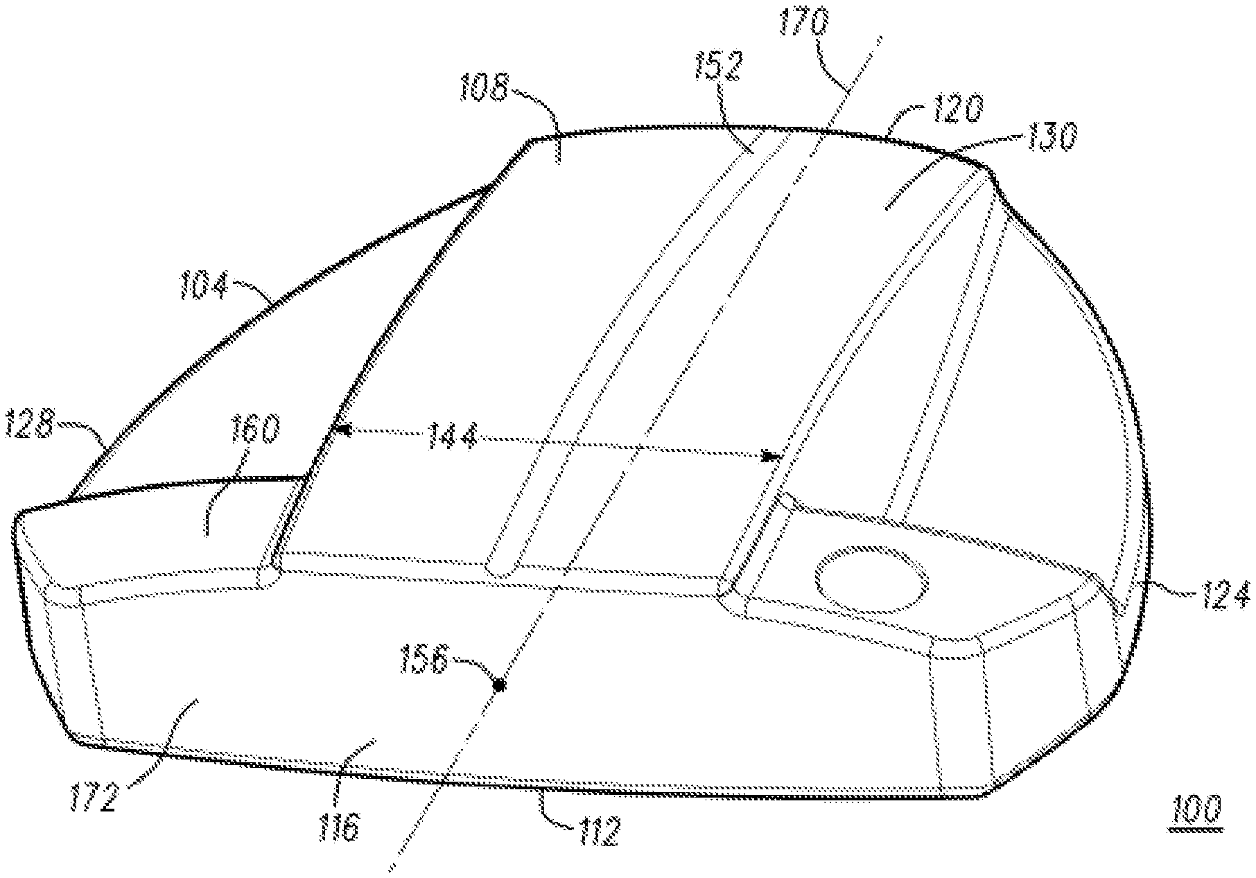
[0004] FIG. 1 illustrates a top perspective view of an embodiment of a putter head with an alignment aid.
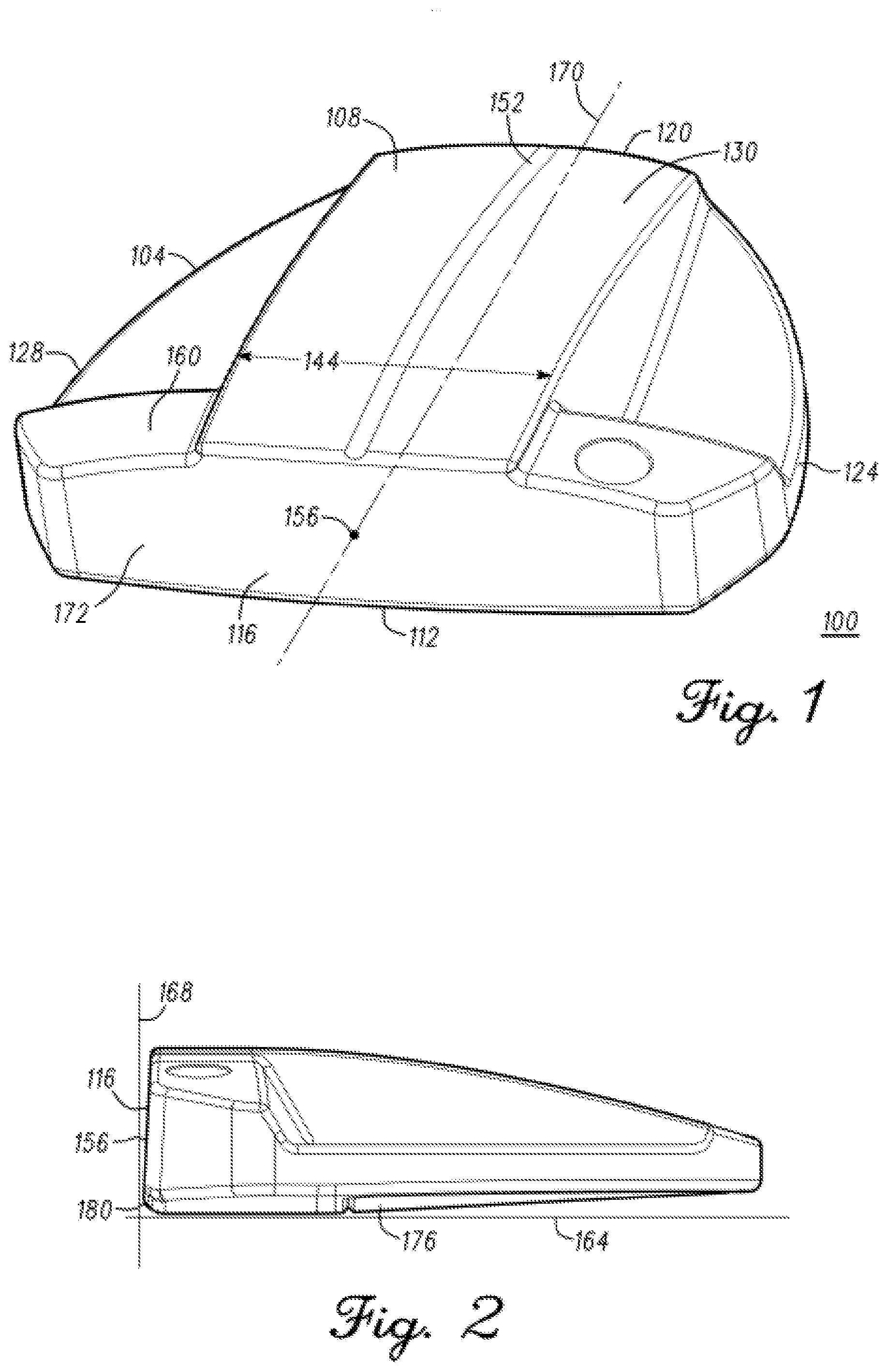
[0005] FIG. 2 illustrates a side view of the putter head in FIG. 1.
[0006] FIG. 3 illustrates a top perspective view of another embodiment of a putter head with an alignment aid.
[0007] FIG. 4 illustrates a side view of the putter head in FIG. 3.
[0008] FIG. 5 illustrates a top perspective view of another embodiment of a putter head with an alignment aid.
[0009] FIG. 6 illustrates a side view of the putter head in FIG. 5.
[0010] FIG. 7 illustrates another embodiment of a putter head with an alignment aid.
[0011] FIG. 8 illustrates a side view of the putter head in FIG. 7.
[0012] FIG. 9 illustrates a method of manufacturing a putter head with an alignment aid.
[0013] FIG. 10 illustrates a rear perspective view of another embodiment of a putter head with an alignment aid.
[0014] Other aspects of the disclosure will become apparent by consideration of the detailed description and accompanying drawings.
[0015] For simplicity and clarity of illustration, the drawing figures illustrate the general manner of construction, and descriptions and details of well-known features and techniques may be omitted to avoid unnecessarily obscuring the present disclosure. Additionally, elements in the drawing figures are not necessarily drawn to scale. For example, the dimensions of some of the elements in the figures may be exaggerated relative to other elements to help improve understanding of embodiments of the present disclosure. The same reference numerals in different figures denote the same elements.
DETAILED DESCRIPTION
[0016] Described herein is a putter type golf club head with an alignment aid positioned on the crown of the club head. The alignment aid indicates the location of the geometric center of the strike face and/or the putter head. The alignment aid also indicates the position of the edges of a golf ball for impact on the center of the strike face. The alignment aid may also allow the user to align the strike face and/or putter head with a golf ball to more consistently achieve center putts. Methods of manufacture and use are also described below.
[0017] The terms "first," "second," "third," "fourth," and the like in the description and in the claims, if any, are used for distinguishing between similar elements and not necessarily for describing a particular sequential or chronological order. It is to be understood that the terms so used are interchangeable under appropriate circumstances such that the embodiments described herein are, for example, capable of operation in sequences other than those illustrated or otherwise described herein. Furthermore, the terms "include," and "have," and any variations thereof, are intended to cover a non-exclusive inclusion, such that a process, method, system, article, device, or apparatus that comprises a list of elements is not necessarily limited to those elements, but may include other elements not expressly listed or inherent to such process, method, system, article, device, or apparatus.
[0018] The terms "left," "right," "front," "back," "top," "bottom," "over," "under," and the like in the description and in the claims, if any, are used for descriptive purposes and not necessarily for describing permanent relative positions. It is to be understood that the terms so used are interchangeable under appropriate circumstances such that the embodiments of the apparatus, methods, and/or articles of manufacture described herein are, for example, capable of operation in other orientations than those illustrated or otherwise described herein.
[0019] The terms "couple," "coupled," "couples," "coupling," and the like should be broadly understood and refer to connecting two or more elements, mechanically or otherwise. Coupling (whether mechanical or otherwise) may be for any length of time, e.g., permanent or semi-permanent or only for an instant.
[0020] The absence of the word "removably," "removable," and the like near the word "coupled," and the like does not mean that the coupling, etc. in question is or is not removable.
[0021] As defined herein, two or more elements are "integral" if they are comprised of the same piece of material.
[0022] Before any embodiments of the disclosure are explained in detail, it is to be understood that the disclosure is not limited in its application to the details of construction and the arrangement of components set forth in the following description or illustrated in the following drawings. The disclosure is capable of other embodiments and of being practiced or of being carried out in various ways.
I. Alignment Aid
[0023] FIGS. 1-2 illustrate a putter head 100 according to one embodiment. The putter head 100 may be a mallet-type putter head, a half-pipe putter head, a blade-type putter head, or another type of putter head; the putter head is not limited in this regard. The putter head described herein may be part of a putter-type golf club. The putter-type golf club may include the putter head, a golf club shaft, and a grip. In some embodiments, the putter head may include a hosel configured to receive the shaft. In some embodiments, the putter head may include a cavity configured to receive the shaft. The shaft may be coupled to the putter head by use of an adhesive such as epoxy, by use of one or more fasteners such as screws, or by other bonding processes such as soldering, welding, and/or brazing.
[0024] The putter head 100 includes a body 104, a crown 108, a sole 112 opposite the crown 108, a face 116, a back 120 opposite the face 116, a heel 124, and a toe 128 opposite the heel 124. The face 116 includes a geometric center 156. The putter head 100 may include a top rail 160 comprising a front portion of crown 108 adjacent to face 116 that extends between the heel 124 and toe 128 of putter head 100. The putter head 100 further includes a centerline 170 and an alignment aid 130. The centerline 170 defines an axis that extends through the geometric center 156, perpendicular to the face 116. The alignment aid 130 includes a sight line 152 and an alignment aid width 144. The alignment aid width 144 is centered about the centerline 170. The alignment aid 130 further includes at least one cavity and/or at least one protruded surface on the crown 108 of the putter head 100. The at least one cavity and/or protruded surface may be aligned perpendicular to the face and have a constant width extending from the face 116 toward the back 120 of the putter head 100.
[0025] The width of the cavity or protruded surface corresponds to the alignment aid width 144 and may be approximately equal to the diameter of a golf ball. Currently, the United States Golf Association (USGA) requires conforming golf balls to have a diameter of not less than 1.680 inches (42.67 mm). In the illustrated embodiment, the alignment aid width 144 is constant and approximately equal to the diameter of a golf ball, or 1.680 inches (42.67 mm). In other embodiments, the alignment aid width 144 may be a constant value greater than 1.176 inches (29.87 mm) and less than 2.184 inches (55.47 mm). Specifically, the alignment aid width 144 may be greater than or equal to approximately 1.2 inches, 1.3 inches, 1.4 inches, 1.5 inches, 1.6 inches, 1.7 inches, 1.8 inches, 1.9 inches, 2.0 inches, or 2.1 inches, or any value greater than 1.176 inches.
[0026] The alignment aid 130 allows a user to properly align the putter head 100 with a golf ball during a swing. Specifically, the sight line 152 can indicate to the user the location of the geometric center 156 of the face 116 of the putter head 100 and enable the user to more easily align the geometric center 156 of the face 116 with the center of the golf ball. Similarly, the alignment aid width 144 allows the user to align the edges of a golf ball such that the golf ball is aligned with the geometric center 156 of the face 116. When a user properly aligns the putter head 100 with the golf ball during a putting stroke, the golf ball rolls more consistently and accurately. Additionally, the alignment aid 130 described herein also allows the user to align the putter head 100 with the outer dimensions of the golf ball as he performs the putting stroke, which increases the likelihood for an on-center hit.
[0027] FIGS. 1-2 illustrate the putter head 100 at an address position relative to a ground plane 164, where the face 116 is positioned at an angle 180 with the ground plane 164. The face 116 may be generally planar. The face 116 may be substantially orthogonal to the ground plane 164 when the putter head 100 is at address position. In other embodiments, angle 180 may be greater than or equal to approximately 80 degrees, 85 degrees, 86 degrees, 87 degrees, 88 degrees, 89 degrees, 90 degrees, 91 degrees, 92 degrees, 93 degrees, 94 degrees, 95 degrees, or any angle greater than 80 degrees and less than 100 degrees. The face 116 defines a face plane 168 tangent to the geometric center 156 of the face 116. The face 116 may include a ball striking face 172 that may be the same size or smaller than the face 116, and that may be used to strike a golf ball (not shown).
[0028] The ball striking face 172 may be a continuous or integral part of the face 116 or formed as an insert that is attached to or within the face 116. The body 104 may be comprised of a first material. The face 116 or insert may be comprised from the first material or may be comprised from a different second material. The insert may be permanently affixed to or within the face 116, or may be removable. The insert may be a metallic or non-metallic material. The non-metallic material may be a polymer, copolymer, polymer composite or any other suitable material. The ball striking face may include one or more grooves such as the grooves described in U.S. Pat. No. 8,790,193, which is incorporated herein by reference.
[0029] In some embodiments, putter head 100 may include one or more weights disposed in the sole 112 in various locations and orientations. For example, putter head 100 may be provided with a plurality of removable weights, which may be disposed within at least one cavity in sole 112. In some embodiments, a single weight may comprise a sole plate 176 disposed within a cavity near a center portion of sole 112 of putter head 100. The sole plate 176 may be used by an individual to increase the total mass of the putter head 100. The sole plate 176 may be secured within the cavity by using an adhesive such as epoxy. Alternatively, the sole plate 176 may be secured by one or more screws or other fasteners. The sole plate 176 may also be secured within the cavity in the sole 112 by a thermal expansion process.
[0030] The body 104, ball striking face 172, and/or sole plate 176 of putter head 100 may be made from any material. For example, the body 104, ball striking face 172, and/or sole plate 176 of putter head 100 may be made from titanium, titanium alloy, other titanium-based materials, steel, stainless steel, aluminum, aluminum alloy, other metals, metal alloys, plastic, wood, composite materials, or other suitable types of materials. The body 104, ball striking face 172, and/or sole plate 176 of putter head 100 may be made from different materials, or they all may be made from the same material. In the illustrated embodiment, body 104 is made from a first material, and the sole plate 176 is made from a second material different from the first material.
A. Mallet-Type Putter with Protrusion
[0031] The putter head may be a mallet-type putter head as shown in FIG. 3-4. Putter head 200 can be similar to putter head 100 (FIG. 1-2). Referring to FIG. 3-4, putter head 200 comprises an alignment aid 230 including a protruded surface located along the crown 208. The alignment aid 230 may be centered about a centerline 270 which extends perpendicular to the face plane 268 from the face 216 to the back 220 of putter head 200 and passes through the geometric center 256 of the face 216. The alignment aid 230 is positioned at least partially in the first 1/3 of the putter head 200. The alignment aid 230 may be positioned at least partially in the first 1/8, or 1/7, or 1/6, or 1/5, or 1/4, or 1/3 of the putter head 200. The alignment aid 230 may be directly adjacent to the face 216 or may be positioned at an offset distance from the face 216. Further, the alignment aid 230 may extend entirely to the back 220 of the putter head 200 or may extend a portion of the way to the back 220 of the putter head 200.
[0032] A portion of alignment aid 230 is disposed above a height of top rail 260, and may form a first and second step 232, 234 with a top rail surface 236 of top rail 260. The first step 232 may be formed between a heel edge 238 of alignment aid 230 and the top rail surface 236 of top rail 260. The second step may be formed between a toe edge 240 of alignment aid 230 and the top rail surface 236 of top rail 260. Additionally, the alignment aid 230 may include a height which remains constant, increases or decreases across its length. In the illustrated embodiment, a first portion 246 of top surface 242 may extend between face 216 and a rear edge 248 of top rail 260 along a path that is linear and orthogonal to face plane 268. A second portion 250 of top surface 242 may extend from the rear edge 248 of top rail 260 to the back 220 of putter head 200 along a curved path sloping downward towards the ground plane 264. However, in any embodiment, the first portion 246 of top surface 242 is positioned higher than the top rail 260.
[0033] In the illustrated embodiment, a top surface 242 of alignment aid 230 has a width 244 which is measured between the heel edge 238 and toe edge 240 of alignment aid 230. The width 244 may be constant, may vary linearly, or may vary non-linearly as top surface 242 extends along the crown 208 between the face 216 and the back 220 of putter head 200. In the illustrated embodiment, the width 244 of top surface 242 is constant and approximately equal to the diameter of a golf ball, or 1.680 inches (42.67 mm). In other embodiments, the width 244 of top surface 242 may be a constant value greater than 1.176 inches (29.87 mm) and less than 2.184 inches (55.47 mm). Specifically, the width 244 of top surface 242 may be greater than or equal to approximately 1.2 inches, 1.3 inches, 1.4 inches, 1.5 inches, 1.6 inches, 1.7 inches, 1.8 inches, 1.9 inches, 2.0 inches, or 2.1 inches, or any value greater than 1.176 inches.
[0034] Referring to FIG. 3-4, top surface 242 of alignment aid 230 extends perpendicular to the face plane 268 along the crown 208 from the face 216 towards the back 220 of putter head 200. A centerline 270 is also perpendicular to face 216 and extends through a geometric center 256 of face 216. A top surface 242 of the alignment aid 230 may be centered with the centerline 270. Top surface 242 may extend linearly from face 216 to back 220 of the putter head 200, or it may extend along a curvilinear path. Further, the top surface 242 of alignment aid 230 may extend between face 216 and back 220 along a path comprising any combination of linear and non-linear segments.
[0035] In the illustrated embodiment, referring to FIG. 3-4, a sight line 252 is disposed on the top surface 242 of alignment aid 230. Sight line 252 may be aligned with centerline 270 when viewed from a top view. Further, the sight line 252 may extend across the entire length of the putter head 200 or any portion of the length of the putter head 200. For example, the sight line may extend from face 216 to back 220 of putter head 200 or may extend from the rear edge 248 of top rail 260 to back 220 of putter head 200. Additionally, sight line 252 may comprise a sight line stripe, where the sight line stripe comprises a first color and the top surface 242 comprises a second color different from the first color. In other embodiments, sight line 252 may comprise a groove in top surface 242. The depth, width, and/or vertical cross-sectional shape of the groove may be constant along the length, or may vary linearly or non-linearly. The groove may include the sight line stripe disposed inside the groove, and the first color may be the same or different from the second color. Sight line 252 may be machined into top surface 242, may be formed by casting, forging, or any other manufacturing process.
[0036] In the illustrated embodiment, putter head 200 may further comprise a first cavity 282 and a second cavity 284 disposed in the surface of crown 208. The first cavity 282 may be disposed in a portion of crown 208 located near or closest to the heel 224, with the first cavity 282 having a first recessed bottom surface 286. The intersection of first cavity 282 and top rail surface 236 may define the rear edge 248 of top rail 260. The intersection of first cavity 282 and alignment aid 230 may define the heel edge 238 of alignment aid 230. Similarly, the second cavity 284 may be disposed in a portion of crown 208 located near or closest to the toe 228, with the second cavity 284 having a second recessed bottom surface 288. The intersection of second cavity 284 and top rail surface 236 may further define the rear edge 248 of top rail 260. The intersection of second cavity 284 and alignment aid 230 may define the toe edge 240 of alignment aid 230. The first and second recessed bottom surfaces 286, 288 of the first and second cavities 282, 284 may each be generally planar, or they may be generally coplanar with each other. In a preferred embodiment, first recessed bottom surface 286 and second recessed bottom surface 288 are coplanar and together define a recessed bottom plane. The recessed bottom plane may be parallel to the ground plane 264 when the putter head 200 is at address position.
[0037] Referring to FIG. 4, a first top rail edge 210 may be defined by the intersection of face 216 and top rail surface 236. A top rail width 218 may be defined as the distance between the first top rail edge 210 and the rear edge 248 of top rail 260. The top rail may include a width 218 and a height which may remain constant, increase or decrease along the length of top rail 260 as top rail 260 extends between heel 224 and toe 228 of putter head 200. The top rail width 218 may be a distance greater than or equal to approximately 0.50 inch. Alternatively, the top rail width 218 may be greater than or equal to approximately 0.35 inch, and may be less than or equal to approximately 0.65 inch. For example, the top rail width 418 may be greater than or equal to approximately 0.35 inch, 0.40 inch, 0.42 inch, 0.44 inch, 0.46 inch, 0.48 inch, 0.50 inch, 0.52 inch, 0.54 inch, 0.56 inch, 0.58 inch, or 0.60 inch, or any other value greater than 0.35 inch.
[0038] In the illustrated embodiment, referring to FIG. 4, a sole plate 276 may be disposed in the sole 212 of putter head 200. The sole 212 of putter head 200 may include a mating section 290 comprised of a sole cavity 292 configured to receive the sole plate 276. The sole plate 276 may have a shape that matches the shape of the sole cavity 292 such that the sole plate 276 fits within the sole 212 of putter head 200, and an outer surface of the sole plate 276 is flush with the surface of sole 212 when assembled. Sole plate 276 may be secured within the mating section 290 by using an adhesive such as epoxy. Alternatively, sole plate 276 may be secured within mating section 290 by one or more screws or other fasteners. Sole plate 276 may also be secured within mating section 290 by a sintering or thermal expansion process.
B. Mallet-Type Putter with Cavity
[0039] The putter head may be a mallet-type putter head as shown in FIG. 5-6. Putter head 400 can be similar to putter head 100 (FIG. 1-2). Referring to FIGS. 5-6, putter head 400 comprises an alignment aid 430 including a cavity 402 disposed at the center of the crown 408. The alignment aid 430 may be centered about a centerline 470 which extends perpendicular to the face plane 468 from the face 416 to the back 420 of putter head 400 and passes through the geometric center 456 of the face 416. The alignment aid 430 is positioned at least partially in the first 1/3 of the putter head 400. The alignment aid 430 may be positioned at least partially in the first 1/8, or 1/7, or 1/6, or 1/5, or 1/4, or 1/3 of the putter head 400. The alignment aid 430 may be directly adjacent to the face 416 or may be positioned at an offset distance from the face 416. Further, the alignment aid 430 may extend from the face 416 entirely to the back 420 of the putter head 400 or may extend a portion of the way to the back 420 of the putter head 400. The cavity 402 may have a recessed bottom surface 406 that is generally planar. Recessed bottom surface 406 may define a recessed bottom surface plane that may be generally parallel to the ground plane 464 when putter head 400 is at address position. The top rail 460 may comprise a front portion of crown 408 adjacent to face 416 that extends between the heel 424 and toe 428 of putter head 400. The cavity 402 may intersect with top rail 460 and may define rear wall 494 of top rail 460. Rear wall 494 may be generally planar, and may be generally parallel to face 416 of putter head 400.
[0040] Top rail 460 may have a top rail surface 436. A first top rail edge 410 may be defined by the intersection of face 416 and top rail surface 436, and a second top rail edge 414 may be defined by the intersection of rear wall 494 and top rail surface 436. A top rail width 418 may be defined as the distance between the first and second top rail edges 410, 414. The top rail width 418 may be constant along the length of top rail 460 as top rail 460 extends between heel 424 and toe 428 of putter head 400. The top rail width 418 may be a distance greater than or equal to approximately 0.50 inch. Alternatively, the top rail width 418 may be greater than or equal to approximately 0.35 inch, and may be less than or equal to approximately 0.65 inch. For example, the top rail width 418 may be greater than or equal to approximately 0.35 inch, 0.40 inch, 0.42 inch, 0.44 inch, 0.46 inch, 0.48 inch, 0.50 inch, 0.52 inch, 0.54 inch, 0.56 inch, 0.58 inch, or 0.60 inch, or any other value greater than 0.35 inch.
[0041] In the illustrated embodiment, putter head 400 may further comprise a first protrusion 422 and a second protrusion 426 disposed on the crown 408. First protrusion 422 may be disposed on a portion of crown 408 located near or closest to the heel 424, with the first protrusion 422 having a first protrusion top surface 454. Second protrusion 426 may be disposed on a portion of crown 408 located near or closest to the toe 428, with the second protrusion 426 having a second protrusion top surface 458. The first and second protrusion top surfaces 454, 458 may be positioned lower than the top rail surface 436. Likewise, the first and second protrusion top surfaces 454, 458 may be positioned higher than the recessed bottom surface 406. Further, the first and second protrusion top surfaces 454, 458 may include a height which remains constant, increases or decreases across their length.
[0042] The intersection of first protrusion 422 and alignment aid 430 may define a first wall 462 of alignment aid 430. Similarly, the intersection of second protrusion 426 and alignment aid 430 may define a second wall 466 of alignment aid 430. The first and second walls 462, 466 may be generally planar and extend from rear wall 494 of top rail 460 to back 420 of putter head 400. First and second walls 462, 466 may be generally perpendicular to rear wall 494, and may be generally parallel to each other. First and second walls 462, 466 may be centered about a centerline 470 which extends perpendicular to face 416 and passes through the geometric center 456 of face 416.
[0043] In the illustrated embodiment, referring to FIG. 5, alignment aid 430 has a width 444 which is measured between first wall 462 of alignment aid 430 and second wall 466 of alignment aid 430. The width 444 of alignment aid 430 is constant and approximately equal to the diameter of a golf ball, or 1.680 inches (42.67 mm). In other embodiments, the width 444 of alignment aid 430 may be a constant value greater than 1.176 inches (29.87 mm) and less than 2.184 inches (55.47 mm). Specifically, the width 444 of alignment aid 430 may be greater than or equal to approximately 1.2 inches, 1.3 inches, 1.4 inches, 1.5 inches, 1.6 inches, 1.7 inches, 1.8 inches, 1.9 inches, 2.0 inches, or 2.1 inches, or any value greater than 1.176 inches.
[0044] The sight line 452 is disposed on the recessed bottom surface 406 of alignment aid 430. Sight line 452 may be aligned with centerline 470 when viewed from a top view. Further, the sight line 452 may extend along recessed bottom surface 406 from rear wall 494 of top rail 460 to back 420 of putter head 400 to define a corresponding length. Sight line 452 may comprise a sight line stripe, where the sight line stripe comprises a first color and the recessed bottom surface 406 comprises a second color different from the first color. In other embodiments, sight line 452 may comprise a groove in recessed bottom surface 406. The depth, width, and/or vertical cross-sectional shape of the groove may be constant along the length, or may vary linearly or non-linearly. The groove may include the sight line stripe disposed inside the groove, and the first color may be the same or different from the second color. Sight line 452 may be machined into recessed bottom surface 406, may be formed by casting, forging, or any other manufacturing process.
[0045] A first groove 474 may be disposed in top rail surface 436. First groove 474 may be coplanar with first wall 462. Similarly, a second groove 478 may be disposed in top rail surface 436, where second groove 478 may be coplanar with second wall 466. Accordingly, a distance between first groove 474 and second groove 478 will be approximately equal to the width 444 of alignment aid 430. When the width 444 of alignment aid 430 is approximately equal to the diameter of a golf ball, or 1.680 inches (42.67 mm), the distance between first groove 474 and second groove 478 is also approximately equal to the diameter of a golf ball, or 1.680 inches (42.67 mm). Thus the first and second grooves 474, 478 may allow a user to more properly align the putter head 400 with the ball during a swing. The depth, width, and/or vertical cross-sectional shape of the first and second grooves may be constant along the length, or may vary linearly or non-linearly. The first groove 474 may include a first stripe disposed inside the first groove, and the second groove 478 may include a second stripe disposed inside the second groove. The first and second stripes may comprise the first color of the sight line stripe. First and second grooves 474, 478 may be machined into top rail surface 436, may be formed by a casting or forging process, or may be formed by any other manufacturing process.
[0046] In the illustrated embodiment, a sole plate 476 may be disposed in the sole 412 of putter head 400. The sole 412 of putter head 400 may include a mating section 490 comprised of a sole cavity 492 configured to receive the sole plate 476. The sole plate 476 may have a shape that matches the shape of the sole cavity 492 such that the sole plate 476 fits snugly within the sole 412 of putter head 400, and an outer surface of the sole plate 476 is flush with the surface of sole 412 when assembled. Sole plate 476 may be secured within the mating section 490 by using an adhesive such as epoxy. Alternatively, sole plate 476 may be secured within mating section 490 by one or more screws or other fasteners. Sole plate 476 may also be secured within mating section 490 by a sintering or thermal expansion process.
C. Blade-Type Putter
[0047] The putter head may be a blade-type putter head as shown in FIGS. 7-8. Putter head 600 can be similar to putter head 100 (FIG. 1-2). Referring to FIG. 7-8, putter head 600 comprises an alignment aid 630 including a cavity 602 disposed at the center of the crown 608. The alignment aid 630 may be centered about a centerline 670 which extends perpendicular to the face plane 668 from the face 616 to the back 620 of putter head 600 and passes through the geometric center 656 of the face 616. The alignment aid 630 is positioned at least partially in the first 1/3 of the putter head 600. The alignment aid 630 may be positioned at least partially in the first 1/8, or 1/7, or 1/6, or 1/5, or 1/4, or 1/3 of the putter head 600. The alignment aid 630 may be directly adjacent to the face 616 or may be positioned at an offset distance from the face 616. Further, the alignment aid 630 may extend from the face 616 entirely to the back 620 of the putter head 600 or may extend a portion of the way to the back 620 of the putter head 600. The cavity 602 may have a recessed bottom surface 606. Recessed bottom surface 606 may define a recessed bottom surface plane that may be generally parallel to the ground plane 664 when putter head 600 is at address position. In other embodiments, recessed bottom surface 606 may be curved and may generally match the curvature of sole 612, such that the surface of sole 612 and recessed bottom surface 606 are generally parallel. The top rail 660 may comprise a front portion of crown 608 adjacent to face 616 that extends between the heel 624 and toe 628 of putter head 600. Cavity 602 and top rail 660 together may define a recessed rear surface 696 of top rail 660. Recessed rear surface 696 may be generally planar, and may be generally parallel to the face 616 of putter head 600. Top rail 660 may have a top rail surface 636 which is generally planar, and top rail surface 636 may be generally parallel to ground plane 664 when putter head 600 is at address position. Recessed rear surface 696 may be circumscribed by a rim portion 698. A first top rail edge 610 may be defined by the intersection of face 616 and top rail surface 636, while a second top rail edge 614 may be defined by the intersection of rim portion 698 and top rail surface 636.
[0048] A top rail width 618 may be defined as the distance between the first and second top rail edges 610, 614. The top rail width 618 may be constant along the length of top rail 660 as top rail 660 extends between heel 624 and toe 628 of putter head 600. The top rail width 618 may be a distance greater than or equal to approximately 0.25 inch. Alternatively, the top rail width 618 may be greater than or equal to approximately 0.18 inch, and may be less than or equal to approximately 0.32 inch. For example, the top rail width 618 may be greater than or equal to approximately 0.18 inch, 0.20 inch, 0.21 inch, 0.22 inch, 0.23 inch, 0.24 inch, 0.25 inch, 0.26 inch, 0.27 inch, 0.28 inch, 0.29 inch, or 0.30 inch, or any other value greater than 0.18 inch.
[0049] In the illustrated embodiment, putter head 600 may further comprise two protrusions disposed on the crown 608. A first protrusion 622 may be disposed on a portion of crown 608 located near or closest to the heel 624, with the first protrusion 622 having a first protrusion top surface 654. A second protrusion 626 may be disposed on a portion of crown 608 located near or closest to the toe 628, with the second protrusion 626 having a second protrusion top surface 658. The first and second protrusion top surfaces 654, 658 may be positioned lower than the top rail surface 636. Likewise, the first and second protrusion top surfaces 654, 658 may be positioned higher than the recessed bottom surface 606. Further, the first and second protrusion top surfaces 654, 658 may include a height which remains constant, increases or decreases across their length.
[0050] The intersection of first protrusion 622 and alignment aid 630 may define a first wall 662 of alignment aid 630. Similarly, the intersection of second protrusion 626 and alignment aid 630 may define a second wall 666 of alignment aid 630. The first and second walls 662, 666 may be generally planar and extend from recessed rear surface 696 of top rail 660 to back 620 of putter head 600. First and second walls 662, 666 may be generally perpendicular to recessed rear surface 696, and may be generally parallel to each other. First and second walls 662, 666 may be centered about a centerline 670 perpendicular to face 616 and extending through the geometric center 656 of face 616.
[0051] In the illustrated embodiment, referring to FIG. 7-8, alignment aid 630 has a width 644 which is measured between first wall 662 of alignment aid 630 and second wall 666 of alignment aid 630. The width 644 of alignment aid 630 is constant and approximately equal to the diameter of a golf ball, or 1.680 inches (42.67 mm). In other embodiments, the width 644 of alignment aid 630 may be a constant value greater than 1.176 inches (29.87 mm) and less than 2.184 inches (55.47 mm). Specifically, the width 644 of alignment aid 630 may be greater than or equal to approximately 1.2 inches, 1.3 inches, 1.4 inches, 1.5 inches, 1.6 inches, 1.7 inches, 1.8 inches, 1.9 inches, 2.0 inches, or 2.1 inches, or any value greater than 1.176 inches.
[0052] The sight line 652 is disposed on the recessed bottom surface 606 of alignment aid 630. Sight line 652 may be aligned with centerline 670 when viewed from a top view. Further, the sight line 652 may extend along recessed bottom surface 606 from recessed rear surface 694 of top rail 660 to back 620 of putter head 600 to define a corresponding length. Sight line 652 may comprise a sight line stripe, where the sight line stripe comprises a first color and the recessed bottom surface 606 comprises a second color different from the first color. In other embodiments, sight line 652 may comprise a groove in recessed bottom surface 606. The depth, width, and/or vertical cross-sectional shape of the groove may be constant along the length, or may vary linearly or non-linearly. The groove may include the sight line stripe disposed inside the groove, and the first color may be the same or different from the second color. Sight line 652 may be machined into recessed bottom surface 606, may be formed by casting, forging, or any other manufacturing process.
[0053] The putter head 600 may have a hosel 702 to which a putter shaft may be coupled. Referring to FIG. 8, hosel 702 may have a hosel body 704 with a first end 706 extending from the heel portion 708 of the hosel body 704, and a second end 710 configured to receive a shaft. The shaft and the hosel 702 may be secured to each other by use of an adhesive such as epoxy, by use of 1 or more fasteners such as screws, or by other bonding processes such as soldering, welding, and/or brazing.
D. Multiple Sight Line Putter Head
[0054] Putter head 1100 of FIG. 10, can be similar to putter head 100 (FIG. 1-2). Referring to FIG. 10, putter head 1100 comprises an alignment aid 1130 including a plurality of sight lines 1152, 1153, 1155 disposed at the center of the crown. The alignment aid 1130 may be centered about a centerline 1170 which extends perpendicular to the face plane 1168 from the face 1116 to the back 1120 of putter head 1100 and passes through the geometric center 1156 of the face 1116. The alignment aid 1130 is positioned at least partially in the first 1/3 of the putter head 1100. The alignment aid 630 may be positioned at least partially in the first 1/8, or 1/7, or 1/6, or 1/5, or 1/4, or 1/3 of the putter head 600. The alignment aid 1130 may be directly adjacent to the face 1116 or may be positioned at an offset distance from the face 1116. Further, the alignment aid 1130 may extend from the face 1116 entirely to the back 1120 of the putter head 1100 or may extend a portion of the way to the back 1120 of the putter head 1100.
[0055] The alignment aid 1130 may have a sight line 1152, a first auxiliary sight line 1153 and a second auxiliary sight line 1155. The sight line 1152 may be aligned with the centerline when viewed from a top view. Further, the sight line may extend perpendicular to the face plane 1168 from the face 1116 to the back 1120 of putter head 1100. The first auxiliary sight line 1153 is offset from the sight line 1152 by a predetermined distance toward the heel of the club head. The second auxiliary sight line 1155 is offset from the sight line 1152 by a predetermined distance toward the toe of putter head 1100. The offset distance for the first auxiliary sight line 1153 and the offset distance for the second auxiliary sight line 1155 is preferably the same distance. The first auxiliary sight line 1153 and the second auxiliary sight line 1155 extend in parallel to the sight line 1152 along the top surface 1142 from the face 1116 to the back 1120 of the putter head 1100. The first and second auxiliary sight lines 1153, 1155 may extend across the same length of the top surface as the sight line 1152 or across a different length. The sight line 1152 comprises a first color which may be any color. The top surface 1142 comprises a second color different from the first color. The first auxiliary sight line 1153 comprises a third color different from the first color and the second color. The second auxiliary sight line 1155 comprises the third color different from the first color and second color. In other embodiments, the second auxiliary sight line 1155 may comprise a fourth color different from the first, second and third color.
[0056] In many embodiments, the first color of the sight line 1152 comprises a bold or primary color. In many embodiments, the third color of the first and second auxiliary sight line 1153, 1155 comprises a muted or secondary color. For example, in some embodiments, the first color can be red, and the third color can be green. In other embodiments, the first color may be red, yellow, blue or any other suitable bold color, while the third color may be purple, green, orange, magenta, cyan or any other suitable muted color. The combination of a bold or primary first color for the sight line 1152 and a muted or secondary third color for the first and second auxiliary sight lines 1153, 1155 can allow the user to relax their eyes and concentrate on the desired ball trajectory, to better align the ball with the target.
[0057] Referring to FIG. 10, the sight line 1152 has a width. The first auxiliary sight line 1153 has a width less than the width of the sight line 1152. The second auxiliary sight line 1155 has a width less than the width of the sight line 1152. In many embodiments, the width of the first auxiliary sight line 1153 is the same as the width of the second auxiliary sight line 1155. The arrangement of a central sight line 1152 with parallel offset auxiliary sight lines 1153, 1155 that are thinner and comprising different colors takes advantage of the phenomena of Vernier Acuity. The arrangement of the auxiliary sight lines 1153, 1155 and the sight line 1152 allows the player's eyes to more naturally stay focused and still on the central sight line to better align the ball with the target, similar to alignment aids on golf balls, as disclosed in U.S. Pat. Nos. 8,663,025 B2 and 8,721,468 B1, which are incorporated herein by reference in their entirety. The alignment aid 1130 illustrated in FIG. 10 can be applied to any type of putter head. For example, the alignment aid 1130 as described herein can be applied to a mallet-type putter head with a protrusion, a mallet-type putter head with a cavity, a blade-type putter head, or any other suitable type of putter head.
[0058] In other embodiments, one or more of the sight line 1152, the first auxiliary sightline 1153 and the second auxiliary sightline 1155 may further comprise a groove. The first auxiliary sight line 1153 groove has a width less than the width of the sight line 1152 groove. The second auxiliary sight line 1155 groove has a width less than the width of the sight line 1152 groove. In many embodiments, the width of the first auxiliary sight line 1153 groove is the same as the width of the second auxiliary sight line 1155 groove. The depth, width, and/or vertical cross-sectional shape of the grooves may be constant along the length, or may vary linearly or non-linearly. The sight line 1152 groove may further comprise the primary or bold first color. The first and second auxiliary sight line 1153, 1155 grooves may further comprise the secondary or muted third color. The depth, width, and/or vertical cross-sectional shape of the grooves may be constant along the length, or may vary linearly or non-linearly.
[0059] FIG. 9 illustrates an exemplary method of manufacturing 1000 the putter head 100. While the method of manufacturing 1000 is described herein with reference to putter head 100, the method of manufacturing 1000 may be used to manufacture any putter head including putter head 200, putter head 400, or putter head 600. The method includes: (1) providing a body 104 made of a first material, the body 104 having a crown 108, a sole 112 opposite the crown 108, a heel 124, a toe 128 opposite the heel 124, a face 116, and a back 120 opposite the face 116; (2) forming at least one cavity or at least one protrusion on the crown 108 of the body 104; and (3) forming a sight line on the surface of the at least one cavity or protrusion.
[0060] The method of manufacturing the putter head 100 is merely exemplary and is not limited to the embodiments presented herein. The method can be employed in many different embodiments or examples not specifically depicted or described herein. In some embodiments, the processes of the method described can be performed in any suitable order. In other embodiments, the method 1000 may include additional processes. For example, the method may also include providing a sole plate 176 made of a second material, and coupling the sole plate 176 to the body 104 to form the putter head 100. The second material may be the same or different than the first material. In other embodiments, one or more processes may be combined, separated, or skipped.
[0061] The body 104 of the putter head 100 may be manufactured by casting, forging, machining, rapid prototyping, layer by layer printing, selective laser sintering, direct metal laser sintering, stereolithography, 3D printing, or any other method. Similarly, the ball striking face 172 of the putter head 100 may be manufactured by casting, machining, rapid prototyping, layer by layer printing, selective laser sintering, direct metal laser sintering, stereolithography, 3D printing, or any other method. Furthermore, the sole plate 176 of the putter head 100 may be manufactured by casting, machining, rapid prototyping, layer by layer printing, selective laser sintering, direct metal laser sintering, stereolithography, 3D printing, or any other method. The body 104 and the sole plate 176 may be assembled by swaging, welding, brazing, or any other method capable of coupling the body 104 to the sole plate 176.
[0062] Clause 1: A putter club head comprising: a body, a face, a back opposite the face, a heel, a toe opposite the heel, a crown, and a sole opposite the crown, an alignment aid centered about a centerline that extends perpendicular to the face and passes through a geometric center of the face, the alignment aid comprising: a protrusion disposed on the crown having a width measured between a heel edge and a toe edge, the width approximately equal to a diameter of a golf ball, and a sight line disposed on a top surface of the alignment aid, the sight line being aligned with the centerline; a first cavity is disposed in the crown near the heel, and a second cavity is disposed in the crown near the toe.
[0063] Clause 2: The putter club head of clause 1, wherein the alignment aid width is approximately 1.68 inches.
[0064] Clause 3: The putter club head of clause 1, wherein the body is made from a first material and the face comprises a face insert, wherein the face insert is made from a second material different from the first material.
[0065] Clause 4: The putter club head of clause 1, wherein the sight line comprises a groove in the top surface.
[0066] Clause 5: The putter club head of clause 1, wherein the sight line comprises a sight line stripe having a first color and the top surface comprises a second color.
[0067] Clause 6: The putter club head of clause 1, wherein a sole plate is disposed in the sole.
[0068] Clause 7: The putter club head of clause 1, wherein the putter club head is mallet-type putter head or a half-pipe putter head or a blade-type putter head.
[0069] Clause 8: A putter club head comprising a body, a face, a back opposite the face, a heel, a toe opposite the heel, a crown, and a sole opposite the crown, an alignment aid centered about a centerline that extends perpendicular to the face and passes through a geometric center of the face, the alignment aid comprising a cavity disposed on the crown having a width measured between a first wall and a second wall of the alignment aid, the width approximately equal to a diameter of a golf ball, a sight line disposed on a recessed bottom surface, the sight line being aligned with the centerline, a first protrusion is disposed on the crown near the heel, a second protrusion is disposed on the crown near the toe.
[0070] Clause 9: The putter club head of clause 8, wherein the alignment aid width is approximately 1.68 inches.
[0071] Clause 10: The putter club head of clause 8, wherein: the body is made from a first material; and the face comprises a face insert, wherein the face insert is made from a second material different from the first material.
[0072] Clause 11: The putter club head of clause 8, wherein the sight line comprises a groove in the recessed bottom surface.
[0073] Clause 12: The putter club head of clause 8, wherein: the sight line comprises a sight line stripe having a first color, and the recessed bottom surface comprises a second color.
[0074] Clause 13: The putter club head of clause 8, wherein a sole plate is disposed in the sole.
[0075] Clause 14: The putter club head of clause 8, wherein the putter club head is mallet-type putter head or a half-pipe putter head or a blade-type putter head.
[0076] Clause 15: A putter club head comprising a body, a face, a back opposite the face, a heel, a toe opposite the heel, a crown, and a sole opposite the crown, an alignment aid centered about a centerline that extends perpendicular to the face and passes through a geometric center of the face, the alignment aid comprising a sight line disposed on the crown surface aligned with the centerline, the sight line comprising a first color, a top surface comprising a second color, a first auxiliary sight line extending parallel to and positioned offset from the sight line at a predetermined distance towards the heel, the first auxiliary sight line comprising a third color and a second auxiliary sight line extending parallel and positioned offset from the sight line at the predetermined distance towards the toe, the second auxiliary sight line comprising the third color.
[0077] Clause 16: The putter club head of clause 15, wherein: the body is made from a first material; and the face comprises a face insert, wherein the face insert is made from a second material different from the first material.
[0078] Clause 17: The putter club head of clause 15, wherein one or more of the sight line, the first auxiliary sight line, and the second auxiliary sight line comprises a groove.
[0079] Clause 18: The putter club head of clause 15, wherein the first auxiliary sight line has a width less than the width of the sight line, and the second auxiliary sight line has a width less than the width of the sight line.
[0080] Clause 19: The putter club of clause 15, wherein: the sight line stripe comprises a primary color; the first auxiliary sight line comprises a secondary color; and the second auxiliary sight line comprises a secondary color.
[0081] Clause 20: The putter club head of clause 8, wherein the putter club head is mallet-type putter head or a half-pipe putter head or a blade-type putter head.
[0082] Replacement of one or more claimed elements constitutes reconstruction and not repair. Additionally, benefits, other advantages, and solutions to problems have been described with regard to specific embodiments. The benefits, advantages, solutions to problems, and any element or elements that may cause any benefit, advantage, or solution to occur or become more pronounced, however, are not to be construed as critical, required, or essential features or elements of any or all of the claims.
[0083] As the rules to golf may change from time to time (e.g., new regulations may be adopted or old rules may be eliminated or modified by golf standard organizations and/or governing bodies such as the United States Golf Association (USGA), the Royal and Ancient Golf Club of St. Andrews (R&A), etc.), golf equipment related to the apparatus, methods, and articles of manufacture described herein may be conforming or non-conforming to the rules of golf at any particular time. Accordingly, golf equipment related to the apparatus, methods, and articles of manufacture described herein may be advertised, offered for sale, and/or sold as conforming or non-conforming golf equipment. The apparatus, methods, and articles of manufacture described herein are not limited in this regard.
[0084] While the above examples may be described in connection with a putter-type golf club, the apparatus, methods, and articles of manufacture described herein may be applicable to other types of golf club such as a driver-type golf club, a fairway wood-type golf club, a hybrid-type golf club, an iron-type golf club, or a wedge-type golf club. Alternatively, the apparatus, methods, and articles of manufacture described herein may be applicable other type of sports equipment such as a hockey stick, a tennis racket, a fishing pole, a ski pole, etc.
[0085] Moreover, embodiments and limitations disclosed herein are not dedicated to the public under the doctrine of dedication if the embodiments and/or limitations: (1) are not expressly claimed in the claims; and (2) are or are potentially equivalents of express elements and/or limitations in the claims under the doctrine of equivalents.
[0086] Various features and advantages of the disclosure are set forth in the following claims.
* * * * *
D00000
D00001
D00002
D00003
D00004
D00005
XML
uspto.report is an independent third-party trademark research tool that is not affiliated, endorsed, or sponsored by the United States Patent and Trademark Office (USPTO) or any other governmental organization. The information provided by uspto.report is based on publicly available data at the time of writing and is intended for informational purposes only.
While we strive to provide accurate and up-to-date information, we do not guarantee the accuracy, completeness, reliability, or suitability of the information displayed on this site. The use of this site is at your own risk. Any reliance you place on such information is therefore strictly at your own risk.
All official trademark data, including owner information, should be verified by visiting the official USPTO website at www.uspto.gov. This site is not intended to replace professional legal advice and should not be used as a substitute for consulting with a legal professional who is knowledgeable about trademark law.