Sensor In Clothing Of Limbs Or Footwear
CABAN; Miroslav ; et al.
U.S. patent application number 16/682942 was filed with the patent office on 2020-05-14 for sensor in clothing of limbs or footwear. The applicant listed for this patent is GTX medical B.V.. Invention is credited to Jurriaan BAKKER, Niek BORGERS, Robin BROUNS, Miroslav CABAN, Vincent DELATTRE, Urs KELLER, Joachim von ZITZEWITZ.
| Application Number | 20200147384 16/682942 |
| Document ID | / |
| Family ID | 64308561 |
| Filed Date | 2020-05-14 |


View All Diagrams
| United States Patent Application | 20200147384 |
| Kind Code | A1 |
| CABAN; Miroslav ; et al. | May 14, 2020 |
SENSOR IN CLOTHING OF LIMBS OR FOOTWEAR
Abstract
A control system for a movement reconstruction and/or restoration system for a patient, comprising a CNS-Stimulation Module, especially an EES-Module, configured and arranged to provide CNS-Stimulation to a patient, and/or a PNS-Stimulation Module, especially an FES-Module, configured and arranged to provide PNS-Stimulation to a patient, a controller configured and arranged to control the CNS-Stimulation Module and/or the PNS-Stimulation Module, and at least one sensor configured and arranged to measure at least one parameter indicative of the movement of at least one limb and/or part of a limb of a patient.
| Inventors: | CABAN; Miroslav; (Eindhoven, NL) ; BORGERS; Niek; (Eindhoven, NL) ; KELLER; Urs; (Eindhoven, NL) ; von ZITZEWITZ; Joachim; (Eindhoven, NL) ; BAKKER; Jurriaan; (Eindhoven, NL) ; DELATTRE; Vincent; (Eindhoven, NL) ; BROUNS; Robin; (Eindhoven, NL) | ||||||||||
| Applicant: |
|
||||||||||
|---|---|---|---|---|---|---|---|---|---|---|---|
| Family ID: | 64308561 | ||||||||||
| Appl. No.: | 16/682942 | ||||||||||
| Filed: | November 13, 2019 |
| Current U.S. Class: | 1/1 |
| Current CPC Class: | A61N 1/36139 20130101; A61B 5/112 20130101; A61B 5/1128 20130101; A61B 2562/0219 20130101; A61B 5/0488 20130101; A61H 3/00 20130101; A61B 5/0077 20130101; A61N 1/0484 20130101; A61B 2562/0223 20130101; A61B 5/6829 20130101; A61B 2090/066 20160201; A63B 21/0552 20130101; A61B 5/1123 20130101; A61B 2090/065 20160201; A61B 5/1071 20130101; A61N 1/321 20130101; A61N 1/36031 20170801; A61N 1/36003 20130101; A61B 5/1116 20130101; A61N 1/0551 20130101; A61B 5/6807 20130101; A61N 1/36062 20170801 |
| International Class: | A61N 1/36 20060101 A61N001/36; A61N 1/04 20060101 A61N001/04 |
Foreign Application Data
| Date | Code | Application Number |
|---|---|---|
| Nov 13, 2018 | EP | 18205817.2 |
Claims
1. A control system for a movement reconstruction and/or restoration system for a patient, comprising: a CNS-Stimulation Module comprising an EES-Module configured and arranged to provide a CNS-Stimulation to a patient; and/or a PNS-Stimulation Module comprising an FES-Module, configured and arranged to provide a PNS-Stimulation to a patient; a controller configured and arranged to control one or more of the CNS-Stimulation Module and the PNS-Stimulation Module; and at least one sensor configured and arranged to measure at least one parameter indicative of the movement of at least one limb or part of a limb or the trunk or the head of a patient.
2. The control system of claim 1, wherein the controller is configured and arranged to adapt the CNS-Stimulation provided by the CNS-Stimulation Module and the PNS-Stimulation provided by the PNS-Stimulation Module based on data provided by the sensor.
3. The control system of claim 1, wherein at least one sensor is arranged at each limb or part of a limb of the patient.
4. The control system of claim 1, wherein the sensor is at least one of an inertial measurement unit (IMU), an optical sensor, a camera, a piezo element, a velocity sensor, an accelerometer, a magnet sensor, a torque sensor, a pressure sensor, a displacement sensor, a contact sensor, an EMG measurement unit, a goniometer, a magnetic field sensor, a hall sensor and/or a gyroscope and/or a motion tracking video camera, or a infra-red camera.
5. The control system of claim 1, wherein the sensor may be configured and arranged to be inserted or integrated into or onto one or more of an exoskeleton, tights, a belt, straps, a stretching band, a knee sock, a sock, and a shoe of the patient.
6. The control system of claim 5, wherein the sensor is configured and arranged to be inserted or arranged in the shoe or into the sole or into the insole of the shoe of the patient.
7. The control system of claim 1, wherein the control system may further comprise an electrode module, which is configured and arranged to stimulate a patient locomotor system.
8. The control system of claim 7, wherein the electrode module may comprise at least one electrode, which is configured and arranged to stimulate the patient locomotor system, wherein the electrode is attached to or arranged at the limb or part of the limb or foot or CNS or spinal circuits, or dorsal roots.
9. The control system of claim 8, wherein each limb is targeted or targetable with at least one electrode.
10. The control system of claim 9, wherein the electrode is configured and arranged for limb cramp stimulation to release cramp or detection of limb cramp.
11. The control system of claim 1, wherein the control system may comprise a pre-warning module, which is configured and arranged to provide a pre-warning signal indicative of providing an upcoming stimulation event.
Description
CROSS-REFERENCE TO RELATED APPLICATION
[0001] The present application claims priority to European Patent Application No. 18205817.2, filed on Nov. 13, 2018. The entire contents of the above-listed application is hereby incorporated by reference for all purposes.
TECHNICAL FIELD
[0002] The present invention relates to a system for controlling a movement reconstruction and/or restoration system for a patient, e.g. in the field of improving recovery after neurological disorders like spinal cord injury (SCI), for example after trauma.
BACKGROUND AND SUMMARY
[0003] Decades of research in physiology have demonstrated that the mammalian spinal cord embeds sensorimotor circuits that produce movement primitives (cf. Bizzi E. et al., Modular organization of motor behavior in the frog's spinal cord. Trends in neurosciences 18, 442-446 (1995); Levine A J. et al., Identification of a cellular node for motor control pathways. Nature neuroscience 17, 586-593, (2014)). These circuits process sensory information arising from the moving limbs and descending inputs originating from various brain regions in order to produce adaptive motor behaviours.
[0004] A spinal cord injury (SCI) interrupts the communication between the spinal cord and supraspinal centres, depriving these sensorimotor circuits from the excitatory and modulatory drives necessary to produce movement.
[0005] A series of studies in animal models and humans showed that electrical neuromodulation of the lumbar spinal cord using epidural electrical stimulation (EES) is capable of (re-)activating these circuits. For example, EES has restored coordinated locomotion in animal models of SCI, and isolated leg movements in individuals with motor paralysis (cf van den Brand R., et al., Restoring Voluntary Control of Locomotion after Paralyzing Spinal Cord njury. Science 336, 1182-1185 (2012); Angeli C A. et al., Altering spinal cord excitability enables voluntary movements after chronic complete paralysis in humans. Brain: a journal of neurology 137, 1394-1409 (2014); Harkema S. et al., Effect of epidural stimulation of the lumbosacral spinal cord on voluntary movement, standing, and assisted stepping after motor complete paraplegia: a case study. The Lancet 377, 1938-1947 (2011); Danner S M et al., Human spinal locomotor control is based on flexibly organized burst generators. Brain: a journal of neurology 138, 577-588 (2015); Courtine G. et al., Transformation of nonfunctional spinal circuits into functional states after the loss of brain input. Nature neuroscience 12, 1333-1342, (2009); Capogrosso M et al., A brain-spine interface alleviating gait deficits after spinal cord injury in primates. Nature 539, 284-288, (2016)).
[0006] EP 2 868 343 A1 discloses a system to deliver adaptive electrical spinal cord stimulation to facilitate and restore locomotion after neuromotor impairment. Inter alia, a closed-loop system for real-time control of epidural electrical stimulation is disclosed, the system comprising means for applying to a subject neuromodulation with adjustable stimulation parameters, said means being operatively connected with a real-time monitoring component comprising sensors continuously acquiring feedback signals from said subject. The feedback signals provide features of motion of a subject, wherein the real-time monitoring component is operatively connected with a signal processing device receiving feedback signals and operating real-time automatic control algorithms. This known system improves consistency of walking in a subject with a neuromotor impairment. A Real Time Automatic Control Algorithm is used, comprising a feedforward component employing a single input-single output model (SISO), or a multiple input-single output (MISO) model. Reference is also made to Wenger N. et al., Closed-loop neuromodulation of spinal sensorimotor circuits controls refined locomotion after complete spinal cord injury, Science Translational Medicine, 6, 255 (2014).
[0007] WO 2002/034331 A2 discloses a non-closed loop implantable medical device system that includes an implantable medical device, along with a transceiver device that exchanges data with the patient, between the patient and the implantable medical device, and between a remote location and the implantable medical device. A communication device coupled to the transceiver device exchanges data with the transceiver device, the implantable medical device through the receiver device, and between the transceiver device and the remote location to enable bi-directional data transfer between the patient, the implantable medical device, the transceiver device, and the remote location. A converter unit converts transmission of the data from a first telemetry format to a second telemetry format, and a user interface enables information to be exchanged between the transceiver device and the patient, between the implantable medical device and the patient through the transceiver device, and between the patient and the remote location through the transceiver device.
[0008] EP 3 184 145 A1 discloses systems for selective spatiotemporal electrical neurostimulation of the spinal cord. A signal processing device receiving signals from a subject and operating signal-processing algorithms to elaborate stimulation parameter settings is operatively connected with an Implantable Pulse Generator (IPG) receiving stimulation parameter settings from said signal processing device and able to simultaneously deliver independent current or voltage pulses to one or more multiple electrode arrays. The electrode arrays are operatively connected with one or more multi-electrode arrays suitable to cover at least a portion of the spinal cord of said subject for applying a selective spatiotemporal stimulation of the spinal circuits and/or dorsal roots, wherein the IPG is operatively connected with one or more multi-electrode arrays to provide a multipolar stimulation. Such system advantageously allows achieving effective control of locomotor functions in a subject in need thereof by stimulating the spinal cord, in particular the dorsal roots, with spatiotemporal selectivity.
[0009] EP 2 652 676 A1 relates to a gesture control for monitoring vital body signs and reuses an accelerometer, or, more precise, sensed accelerations of a body sensor for user control of the body sensor. This is achieved by detecting predefined patterns in the acceleration signals that are unrelated to other movements of the patient. These include tapping on/with the sensor, shaking, and turning the sensor. New procedures are described that make it possible to re-use the acceleration sensing for reliable gesture detection without introducing many false positives due to non-gesture movements like respiration, heartbeat, walking, etc. Similar solutions for tapping detection of a user are known from U.S. Pat. Nos. 8,326,569 and 7,742,037.
[0010] WO 2007/047852 A2 discloses systems and methods for patient interactive neural stimulation and/or chemical substance delivery. A method in accordance with one embodiment of the invention includes affecting a target neural population of the patient by providing to the patient at least one of an electromagnetic signal and a chemical substance. The method can further include detecting at least one characteristic of the patient, with the characteristic at least correlated with the patient's performance of an adjunctive therapy task that is performed in association with affecting the target neural population. The method can still further include controlling at least one parameter in accordance with which the target neural population is affected, based at least in part on the detected characteristic.
[0011] WO 2017/062508 A1 discloses a system for controlling a therapeutic device and/or environmental parameters including one or more body worn sensor devices that detect and report one or more physical, physiological, or biological parameters of a person in an environment. The sensor devices can communicate sensor data indicative of the one or more physical, physiological, or biological parameters of a person to an external hub that processes the data and communicates with the therapeutic device to provide a therapy (e.g., neuromodulation, neurostimulation, or drug delivery) as a function of the sensor data. In some embodiments, the therapeutic device can be implanted in the person. In some embodiments, the therapeutic device can be in contact with the skin of the person. The sensor devices can also communicate to the hub that communicates with one or more devices to change the environment as a function of the sensor data.
[0012] WO 2010/021977 A1 describes an orthotic apparatus for use in providing improved range of motion which allows the amount of stretch to be hydraulically powered and measured by the device but controlled by the user. Because the apparatus accurately calculates the amount of stretch, the user, together with the user's physician and therapist, can develop a rehabilitation plan based on accurate measurements. Progress is based on tangible results rather than the user's ability to tolerate pain.
[0013] EP 2 966 422 A1 describes a method for measuring parameters, such as human weight in motion. The method provides registration of signals generated by load sensors disposed in shoe insoles. Each insole has at least two load sensors, with one mounted near the heel region and the other near the toe region of foot. The specific type of motor activity is determined based on temporal correlation of the load sensor signals from both insoles and values thereof. The person's weight, including additionally carried weight, is determined by summing up load sensor signals, for a specific type of motor activity. The invention provides for the measurement of person's weight, including additionally carried weight, in real time for different types of motor activity, such as running, walking at different pace, standing.
[0014] DE 102015220741 A1 describes methods and devices for detecting dyskinetic movement disorders of a person with sensors arranged on the leg, arm and/or upper body. The sensors measure the rotation rates about a first axis parallel to the tibia, forearm and/or upper body, the rotation rates about a second axis perpendicular to the first axis and the rotation rates about a third axis or rotation rates about three axes of the leg, arm and/or upper body, some of which are non-collinear, both perpendicular to the second axis and perpendicular to the first axis. In a data processing system connected to the sensors, a value that can be assigned to a dyskinesia is calculated. Furthermore, this value is stored as a dyskinetic value, in comparison with other values as an average dyskinesis value or as a value for a dyskinetic movement disorder in comparison with at least one predetermined value.
[0015] According to the state of the art, smooth movements comparable to healthy subjects still cannot be achieved by the subject. There is a lack to have a system which overcomes the drawbacks of the prior art. In particular, there is the need of a system stimulating the patient not as a robot. A good roll of the foot and no parasitic movements are necessary during walking and smooth movements are necessary during any other movement including but not limited to cycling and/or swimming and/or rowing and/or stepping and/or sitting down and/or standing up. Thus, the goal of applying stimulation is not to control the patient as a robot, but to support the patient during training and daily life activities, including but not limited to walking and/or cycling and/or swimming and/or rowing and/or stepping and/or sitting down and/or standing up and/or or any other movement. Hence, a control system should be able to determine movement events, e.g. gait events, with criteria that are common to all kind of healthy or pathological movement, e.g. gait, and should support the patient's own natural control loop composed of the brain, nervous system, and sensory organs.
[0016] It is an object of the present invention to improve a neurostimulation system, e.g. in the field of improving recovery after neurological disorders like spinal cord injury (SCI), for example after trauma, especially in adding a control system for a movement reconstruction and/or restoration system for a patient.
[0017] This object is solved according to the present invention by a control system for a movement reconstruction and/or restoration system for a patient, with the features of claim 1. Accordingly, a control system for a movement reconstruction and/or restoration system for a patient, comprising
[0018] a CNS-Stimulation Module, especially an EES-Module, configured and arranged to provide CNS-Stimulation to a patient;
[0019] and/or a PNS-Stimulation Module, especially an FES-Module, configured and arranged to provide PNS-Stimulation to a patient;
[0020] a controller configured and arranged to control the CNS-Stimulation Module and/or the PNS-Stimulation Module; and
[0021] at least one sensor configured and arranged to measure at least one parameter indicative of the movement of at least one limb and/or part of a limb and/or trunk and/or the head of a patient.
[0022] The invention is based on the basic idea that in the context of neuromodulation, especially neurostimulation, the electrical stimulation parameters defining the stimulation in a movement reconstruction and/or restoration system for a patient can be controlled with said system by knowing in greater detail the position and/or current situation of at least one limb and/or at least one part of a limb such as a foot and/or a hand and/or the trunk and/or the head and/or other parts of the body of a patient. In particular, it has been found that the movement of at least one limb and/or at least one part of a limb such as a foot and/or a hand and/or the trunk and/or the head and/or other parts of the body of a patient can be used to predict more clearly the intended and/or ongoing movement and also to find out, which support the patient really needs from the system. The use of a general hardware concept including a PNS-Stimulation Module and/or a CNS-Stimulation Module, a controller, and at least one sensor configured and arranged to measure at least one parameter indicative of the movement and/or the movement speed of the head and/or trunk and/or waist and/or at least one limb and/or at least one part of a limb of a patient combined into one strategy and made available for a patient being equipped with the system enables to allow triggering the stimulation based on the movement crossing a certain threshold. Joint movements are calculated using rigorous mathematical protocols and movement abnormalities are identified by comparing a patient results to an average healthy subject. The control system may interfere with the feedback loop of the patient to enable smooth motion, e.g. a regular gait cycle, with a regular and characteristic movement of at least one limb and/or at least one part of a limb (e.g. foot) and/or another part of the body of the patient, comparable to a healthy subject. Alternatively, e.g. ground reaction forces could be measured by e.g. pressure sensors, and also other sensors could be used to measure the motion and/or position of at least one limb and/or part of a limb such as a foot and/or a hand and/or the trunk and/or the head and/or other parts of the body of a patient.
[0023] The system can be used for treatment related but not limited to restoring and or training of the movements of the patient. Such a movement could be e.g. walking, running, stepping, swimming, rowing or cycling.
[0024] By directly and/or indirectly attaching one or more sensors to at least one foot and/or another part of a leg, including but not limited to the shank and/or thigh and/or hip and/or other parts of the body including but not limited to the trunk, and/or one or two arms and/or one or two hands and/or another part of an arm and/or the head and/or the neck of the patient a precise description of the movement, e.g. angular velocity and angle during the motion, e.g. during gait cycle, can be determined to realize the reorganization of the various phases, e.g. gait phase.
[0025] The controller may be a body-worn platform that processes data that is acquired among others from the sensor and the CNS-Stimulation Module and/or the PNS-Stimulation Module to deliver the correct stimulation when a certain threshold is reached.
[0026] Neural stimulation may be achieved by electrical stimulation, optogenetics (optical neural stimulation), chemical stimulation (implantable drug pump), ultrasound stimulation, magnetic field stimulation, mechanical stimulation, etc.
[0027] Known electrical stimulation systems use either Central Nervous System (CNS) Stimulation, especially Epidural Electrical Stimulation (EES), or Peripheral Nervous System (PNS) Stimulation, especially Functional Electrical Stimulation (FES). Epidural Electrical Stimulation (EES) is known to restore motor control in animal and human models and has more particularly been shown to restore locomotion after spinal cord injury by artificially activating the neural networks responsible for locomotion below the spinal cord lesion (Capogrosso M et al., A Computational Model for Epidural Electrical Stimulation of Spinal Sensorimotor Circuits, Journal of Neuroscience, 33 (49), 19326-19340 (2013); Courtine G. et al., Transformation of nonfunctional spinal circuits into functional states after the loss of brain input, Nat Neurosci. 12(10), 1333-1342 (2009); Moraud E M et al, Mechanisms Underlying the Neuromodulation of Spinal Circuits for Correcting Gait and Balance Deficits after Spinal Cord Injury, Neuron, 89(4), 814-828 (2016)). EES does not directly stimulate motor-neurons but the afferent sensory neurons prior to entering into the spinal cord. In this way, the spinal networks responsible for locomotion are recruited indirectly via those afferents, restoring globally the locomotion movement by activating the required muscle synergies.
[0028] PNS-Stimulation systems used to date in the clinic are known as Functional Electrical Stimulation (FES) that provides electrical stimulation to target muscles with surface electrodes, either directly through stimulation of their motorfibers (neuro-muscular stimulation), or through a limited set of reflexes (practically limited to the withdrawal reflex) or through transcutaneous stimulation the peripheral nerves. The resulting muscle fatigue has rendered FES unsuitable for use in daily life. Furthermore, successes have remained limited through cumbersome setups when using surface muscle stimulation, unmet needs in terms of selectivity (when using transcutaneous nerve stimulation) and a lack of stability (impossible to reproduce exact electrode placement on a daily basis when stimulating muscles, moving electrodes due to clothes, sweating).
[0029] It is possible to provide neuromodulation and/or neurostimulation with the system to the CNS with a CNS-Stimulation Module and/or to the PNS with a PNS-Stimulation Module. Both CNS and PNS can be stimulated at the same time or also intermittently or on demand. These two complementary stimulation paradigms can be combined into one strategy and made available for a patient being equipped with the system. For example, neuromodulation and/or neurostimulation of the CNS may be used to enhance and/or restore the capabilities of the patient in terms of movement, especially in a way that the existing ways of physiological signal transfer in the patient's body are supported such that the command signals for body movement or the like still are provided by the patient's nervous system and just supported and/or enhanced or translated by the CNS-Stimulation Module. The stimulation provided by the PNS-Stimulation Module may be used to specifically steer and direct stimulation signals to specific peripheral nervous structures in order to trigger a specific movement and/or refine existing movements. Such a PNS-Stimulation may be used to refine and/or complete motion and/or the patient's capabilities of movement. It can be e.g. used to complete flexion or extension, lifting, turning or the like of inter alia but not limited to toes, fingers, arms, feet, legs or any extremities of the patient. This can be e.g. done in cases where it is realized that the neuromodulation and/or neurostimulation provided by the CNS-Stimulation Module is not sufficient to complete a movement or of the patient. Then, such a movement or intended status may be completed or supported by stimulation provided by the PNS-Stimulation Module. The PNS-Stimulation can be also used to reduce side effects or compensate for imprecisions of the CNS-Stimulation.
[0030] EES can be phasic or tonic, selective PNS-Stimulation is always phasic. Here, phasic is defined as locked to defined events in the sensing signals (decoded intention, continuous decoding, muscle activity onset, movement onset, event during defined movement (foot off or foot strike during walking for instance).
[0031] By PNS-Stimulation, a stimulation of the upper limb nerves, i.e. the radial, ulnar and/or median nerves can be provided. Also, stimulation of the lower limb nerves like the sciatic and/or femoral nerves can be provided by PNS-Stimulation. All PNS-Stimulation can be done by targeting one of the above-mentioned nerves with intra-neural electrodes (transversal or longitudinal) or epi-neural (cuff) electrodes.
[0032] By CNS-Stimulation the following nervous structures may be stimulated: for the upper limb movements the cervical spinal cord or hand/arm motor cortex may be stimulated with the CNS-Stimulation Module. For the lower limb movements, the lumbosacral spinal cord may be stimulated. All these nerves can be targeted with epidural, subdural or intra-spinal/intra-cortical stimulation.
[0033] Both PNS and CNS-Stimulation Modules may comprise implantable pulse generators (IPGs). IPGs can be used for providing the necessary stimulation current and signals for the CNS-Stimulation Module and the PNS-Stimulation Module.
[0034] The IPG produces the stimulation pulses that are delivered by a lead that may comprise a lead cable and an electrode module comprising multiple electrodes to the stimulation site, e.g. the spinal cord. For EES, the lead is positioned in the epidural space (i.e. on the outside of the dural sac, which encases the spinal cord and the cerebrospinal fluid in which the spinal cord `floats`), on top of the spinal cord (including but not limited to the segments T12, L1, L2, L3, L4, L5, and S1 bilaterally).
[0035] It is also possible that two separated IPGs are provided, one for the PNS-Stimulation Module and one for the CNS-Stimulation Module.
[0036] The stimulation parameters for the PNS-Stimulation and the EES may be frequency, amplitude, pulse-width and the like.
[0037] Both, the CNS-Stimulation Module and PNS-Stimulation Module, as well as the combination of these stimulation modules/systems may be used in a sub-motor threshold region, i.e. an amplitude or configuration at which neuronal sensation but no motor response is evoked.
[0038] The stimulation may be performed in an open-loop manner, where a pre-defined fixed stimulation is executed without adapting to e.g. the motion of the patient. The stimulation settings may then be determined by the therapist or physiotherapist. The movement of the patient may be recorded.
[0039] The stimulation may be performed in a closed-loop manner, where feedback is used to adjust the stimulation to the movement of the patient, including but not limited to walking, running, swimming, cycling, rowing, stepping, standing up or sitting down.
[0040] The system may be also applied for a patient being supported by an external device, including but not limited to a body-weight support, a walker or crutches.
[0041] Moreover, the controller may be configured and arranged to adapt the stimulation provided by the CNS-Stimulation Module and/or the PNS-Stimulation Module on the basis of data provided by the sensor.
[0042] The controller may be used to adapt the movement phase estimation, e.g. gait phase estimation, to the specific movement, e.g. gait, of the patient. For instance, the angle and angular velocity may vary between patients, as well as for a single patient between both limbs and/or part of limbs and for different walking speeds and different assistive devices, including but not limited to a body-weight support, walker or crutches. Similarly, especially for impaired gait, not all gait events may always be present. As walking is a periodic motion, all measured signals may also be periodic. Hence, it may be possible to estimate the cadence by extracting the base frequency of the measured signals. The measured movement (or angle and/or angular velocity) may be also indicative for the current pathophysiological movement or position at the very specific moment. It can be used to correct the position and movement.
[0043] Furthermore, at least one sensor may be arranged at each limb or part of a limb and/or the head and/or the trunk of the patient.
[0044] Using one sensor for one limb or part of a limb allows to obtain limb and/or food position estimates by double integration of the measured acceleration in combination with drift correction.
[0045] For walking, said sensor may be intended to be placed on the foot to get to most information possible about the gait. The feet may be chosen as these are the lower body segments that experience the largest accelerations and angular velocities. In particular, two or more sensors placed on one foot may provide a precise description of the cadence, swing phase, stance phase, in sum including the events toe-off, midswing, heel strike, flat foot, midstance and/or heel-off can be identified. The same events and parameters can be identified for the other foot of the patient. By combining signals of both feet, together with the gait phase and cadence of the stimulation input, a reliable gait phase and cadence estimate can be provided.
[0046] The level of agreements and discrepancies between motion of the left and right foot, and the stimulation input, can be used to give an indication of the gait phase estimation reliability, e.g., the measured cadence of the left foot should be equal to the measured cadence of the right foot and the cadence of the provided stimulation, and the left foot and right foot should be (roughly) in anti-phase.
[0047] Said sensors may be lightweight and wearable, thus the sensors may not hamper the movement of the patient.
[0048] The sensor can be wirelessly connected to the other components of the system.
[0049] However, also a wired connection may be possible and used.
[0050] Moreover, the sensor may be or may comprise at least one of an inertial measurement unit (IMU), an optical sensor, a camera, a piezo element, a velocity sensor, an accelerometer, a magnet sensor, a torque sensor, a pressure sensor, a force sensor, a displacement sensor, a contact sensor, an EMG measurement unit, a goniometer, a magnetic field sensor, a hall sensor and/or a gyroscope and/or a motion tracking video camera, or a infra-red camera.
[0051] Some sensors may require fixed base station in the environment, including but not limited to magnet sensors or infra-red sensors.
[0052] Electromagnetic position sensors, optical sensors and cameras may estimate 3D position and orientation.
[0053] In particular, magnetic sensors and magnetic field sensors may be incorporated in shoes for walking on a magnetic sensor plate or inserted in the treadmill or gait phase detection device. The magnetic force may be detected and acquired by magnetic sensors under gait training.
[0054] Torque sensors may be placed on a bicycle crank for assessing the torque during cycling.
[0055] Some sensors may be worn by the patient without acquiring fixed base station, including but not limited to piezo elements, pressure sensors and/or torque sensors.
[0056] Said IMU may measure and report 3D accelerations, 3D angular velocities and 3D orientation using a combination of one or more of an accelerometer, one or more gyroscopes, and optionally one or more of a magnetometer. Optionally, a temperature sensor may also be included to compensate for the effect of temperature on sensor readings. By integrating the angular velocity assessed by said one or more gyroscopes and fusing with data from said one or more accelerometers, it may be possible to get a precise measurement of the angle of the foot. This angle may have a regular and characteristic pattern for a healthy subject but not for an injured patient. Based on these measurements the orientation of the IMU with respect to the fixed world can be estimated accurately, using standard sensor fusion algorithms.
[0057] By directly and/or indirectly attaching one or more sensors, e.g. IMUs, to the to at least one foot and/or another part of a leg, including but not limited to the shank and/or thigh and/or hip and/or other parts of the body including but not limited to the trunk, and/or at least one arm and/or one at least one hand and/or another part of an arm and/or the head and/or the neck of the patient the angular velocity and angle of at least one foot and/or another part of a leg, including but not limited to the shank and/or thigh and/or hip and/or other parts of the body including but not limited to the trunk, and/or at least one arm and/or at least one hand and/or another part of an arm and/or the head and/or the neck of the patient during motion, e.g. gait cycle, may be determined to realize the reorganization of the various motion phases, e.g. gait phase. Thanks to the angle it may be possible to compute the acceleration of the at least one foot and/or another part of a leg, including but not limited to the shank and/or thigh and/or hip and/or other parts of the body including but not limited to the trunk, and/or at least one arm and/or at least one hand and/or another part of an arm and/or the head and/or the neck of the patient in forward direction. However, also acceleration in any other direction may theoretically be determined. For example, the angle of the ankle joint varies during gait cycle with different gait events (including but not limited to toe-off, midswing, heel strike, foot flat and midstance, heel-off). This information may allow to distinguish stance and swing for a subject, e.g. an injured patient. The angle of at least one limb and/or part of a limb (including one or more joints) of a patient may be used to predict the intended and/or ongoing motion. Further, the angle of at least one limb and/or part of a limb may also be used to find out, which support the patient really needs from the control system. For open loop walking, a change in limb angle and/or part of a limb angle (including joints, e.g. ankle joint) over a certain threshold may be used to initiate a certain stimulation sequence. As just one example, the gait event heel-off may trigger the stimulation for one or more complete gait cycles. However, also other gait events, including but not limited to toe-off, midswing, heel strike, foot flat and midstance may trigger stimulation for one or more complete gait cycles. The acceleration data is sensitive to any shake during the movement, e.g. gait cycle. So, movement can be detected and therefrom also a signal derived, which is indicative for an angle, e.g. the foot angle. Similarly, single events of other periodic movements (including but not limited to running, stepping, cycling, swimming, rowing standing up or sitting down) may trigger the stimulation for one or more complete movement cycles.
[0058] For closed-loop cycling, measuring the pedal phase can simply be achieved by attaching a sensor, e.g. an IMU, to the crank of the bicycle and/or directly or indirectly to at least one foot of the patient. The pedal phase is then defined as the crank angle or the foot angle, which is directly linked to the IMU orientation. The pedal phase can be predicted given the current crank angle or foot angle and angular velocity (both directly provided by placing an IMU on a bicycle crank or at least one foot of a patient).
[0059] The sensor may be configured and arranged to be inserted and/or integrated into and/or onto an exoskeleton, tights, a belt, straps, a stretching band, a knee sock, a sock and/or a shoe of the patient.
[0060] Socks and tights may consist of or may comprise a piezoelectric textile sensor integrated in the trunk, waist, hip, knee, heel and/or toe area. An electrical response according to a mechanical stretching, pressing or pulling is delivered. In particular, socks or tights may be equipped with electrodes and/or electro conductive yarn.
[0061] The sensor may be configured and arranged to be inserted and/or arranged in the shoe and/or into the sole and/or into the insole of a shoe of the patient.
[0062] At least one shoe and/or at least one shoe sole and/or at least one shoe insole may be equipped with one or more sensors. Said one or more sensors may be placed in the heel area and/or the metatarsal area and/or the toe area. In particular, said one or more sensors may be placed either on top of the instep, at the back of the heel, and/or below the heel of the foot (e.g. in a pocket in the sole of the shoe or as an inlay sole), and/or on the sides of the foot, and/or on top of the toes. In this way, real-time and non-real-time reconstruction of foot trajectories may be done up to a few centimeters accuracy.
[0063] We define real-time as an end-to-end latency that is less than 100 ms, preferably less than 50 ms.
[0064] In particular, pressure sensors or contact sensors may be of interest in this regard for motion analysis, e.g. gait analysis. In particular, two or more pressure sensors placed on one foot may provide a precise map of the foot force. In particular, two or more sensors placed on one insole and/or sole may provide a precise description of the cadence, swing phase, stance phase, including the events toe-off, midswing, heel strike, flat foot, midstance and/or heel-off can be identified. The same events and parameters can be identified for the other foot of the patient. By combining signals of both feet, together with the gait phase and cadence of the stimulation input, a reliable gait phase and cadence estimate can be provided. For example, when a sensor is place at the heel area, lifting the foot will result in a change of pressure or the like. Also, when thinking of a piezo element in a sock or other wearable, the movement will change the applied tension on the piezo element and the sock or other wearable. Similar functionality can be used at different positions of the body of the patient.
[0065] For closed-loop cycling, measuring the pedal phase may simply be achieved by attaching a sensor, e.g. an IMU, to the crank of the bicycle or to at least one foot of the patient. The pedal phase may then be defined as the crank angle or the foot angle, which is directly linked to the IMU orientation.
[0066] The foot position, and thus the pedal position, varies during the crank cycle. For example, at low pedaling frequencies (up to 85 rpm), the heel is lowered, and the toes slightly raised when pushing, while the toes point downwards when pulling. These angles may be reflected in the position of the pedal. Therefore, the pedal phase may be predicted given the current crank angle and angular velocity (both directly provided by placing an IMU on a bicycle crank).
[0067] The control system may further comprise an electrode module, which is configured and arranged to stimulate the patient locomotor system.
[0068] Said electrodes may be implanted and have fixation elements for anchoring the electrodes in the surrounding structures at the implantation side. Motor nerves and/or sensory nerves and/or muscles may be stimulated using electrical current pulses. Given this starting point, different stimulation parameters may be identified:
[0069] electrode configuration (which electrodes to use, polarity)
[0070] stimulation (pulse) amplitude
[0071] stimulation (pulse) width
[0072] stimulation (pulse) frequency
[0073] In particular, the electrode module may comprise at least one electrode, which is configured and arranged to stimulate the patient locomotor system, especially wherein the electrode is attached to and/or arranged at the limb and/or part of the limb and/or foot and/or CNS and/or spinal circuits, in particular dorsal roots.
[0074] In particular, each limb may be targeted and/or targetable with at least one electrode. Thus, each limb may be targeted by electrodes of the PNS-Stimulation Module and/or the CNS-Stimulation Module.
[0075] Stimulation of one or more limbs and/or one or more parts of a limb does not necessarily require stimulation on the locomotor system of one or more limbs and/or one or more parts of the limb, respectively, directly. As just one example, the spinal cord or the upper leg may be stimulated to induce a reflex and/or motion of the foot.
[0076] Furthermore, the at least one electrode may be configured and arranged for limb cramp stimulation to release cramp and/or detection of limb cramp.
[0077] In particular, a sensing electrode or an EMG measurement unit may sense muscle activity by means of surface or intramuscular EMG electrodes for flexors and extensors. In case of a cramp, compensatory stimulation may be delivered by the electrode(s). Stimulation patterns may vary depending on different parameters including but not limited to where the cramp is detected and/or intensity of the cramp.
[0078] If the measured movement and/or angle indicates that the foot position needs further correction, such correction may be provided directly by the electrode(s). Similar approaches may be used for other parts of the limbs.
[0079] Furthermore, the control system may comprise a pre-warning module, which is configured and arranged to provide a pre-warning signal indicative of providing an upcoming stimulation event.
[0080] Regulating the movement, e.g. gait, to a predefined reference interferes with voluntary motion of the patient. In particular, voluntary motion of the patient may have a large effect on the movement, as the patients' voluntary control may modulate the muscle activation. The movement pattern may therefore differ from comparable to a healthy subject, to impaired or reduced despite identical stimulation. The pre-warning signal may help the patient to adjust voluntary control to the respective movement planed, thus a regular movement may be performed. The pre-warning signal may include but is not limited to a sound signal, vibration, light signal, smell, taste, pain, temperature (warm, cold), humidity, draught, or the like.
[0081] In particular, the pre-warning signal may act in a sub-motor threshold region at which a sensation is evoked, but not a motor response.
[0082] There may be a communication module WSN. The communication module WSN may be a wireless network between the one or more sensors and the controller. Based on the motion feedback from the one or more sensor (s), the controller needs to be able to provide accurate gait phase and cadence estimates.
[0083] There may be a telemetry module TEL. The communication module TEL may be a wireless link between the controller and the EES Module and/or the controller and the FES Module. TEL may send data from the controller and receive by IPG. This also may include error-correction, retries, etc. The subsystem TEL may communicate commands including but not limited to or stopping the task. The telemetry module may be or may comprise a near field magnetic induction module (NFMI).
[0084] In the following it is identified which control output parameters exist and their effects on the afferent nerves, as well as their end effects on muscle activation is described. Based on this, we select which output parameters will be controlled by the control system.
BRIEF DESCRIPTION OF THE FIGURES
[0085] Further details and advantages of the present invention shall now be disclosed in connection with the drawings.
[0086] It is shown in
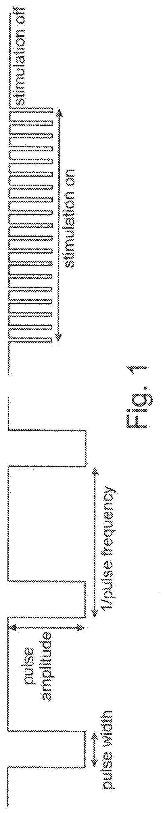
[0087] FIG. 1 a schematic, very simplified representation of a stimulation pulse delivered by a system according to the present invention;
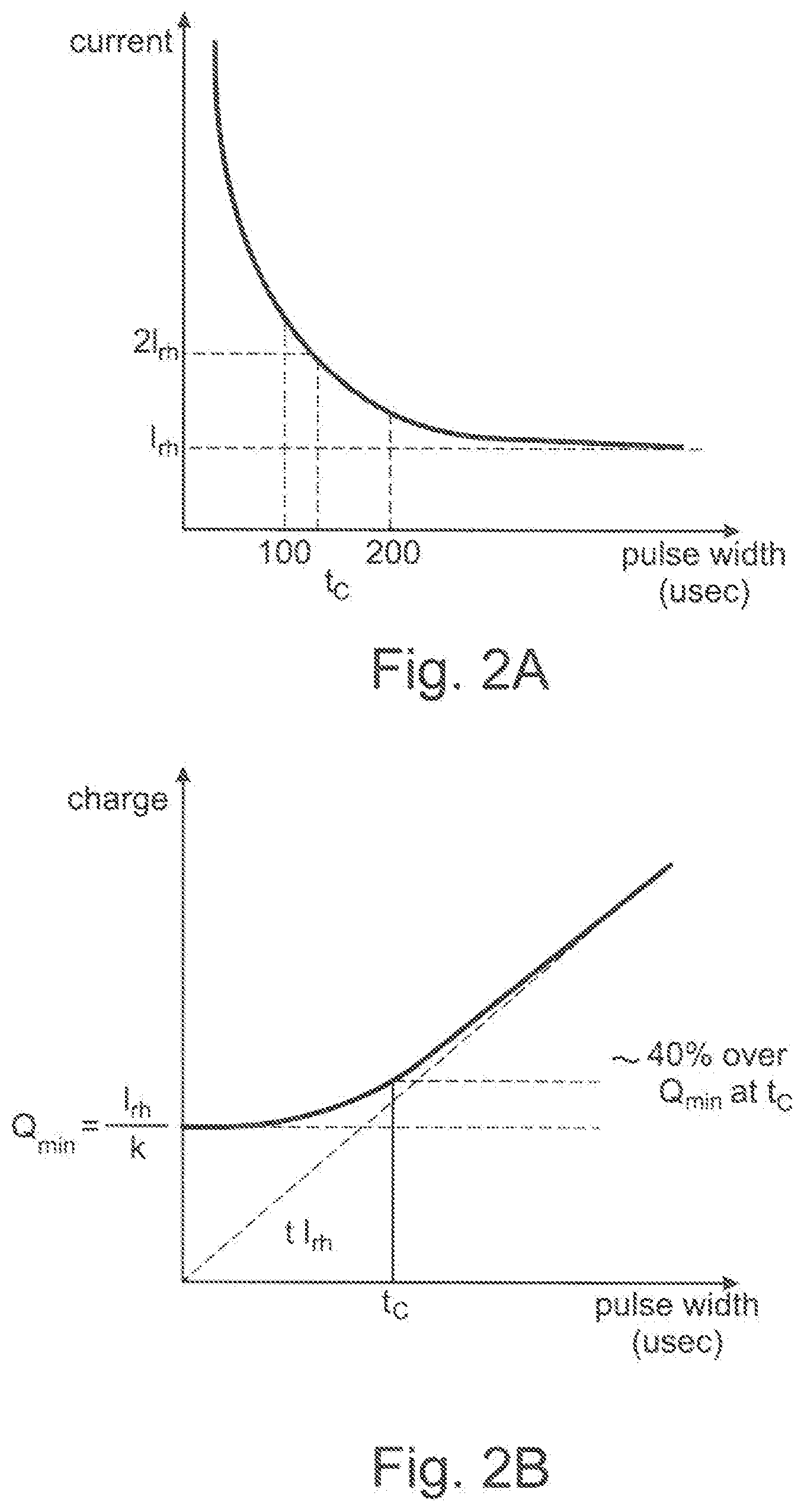
[0088] FIG. 2A, B the necessary current and necessary charge to trigger an action potential in a nerve fiber as a function of the pulse width (using a square pulse);
[0089] FIG. 3 a table specifying the fiber types, diameter, and function;
[0090] FIG. 4 the relationship between response delay and inter-muscle response delays;
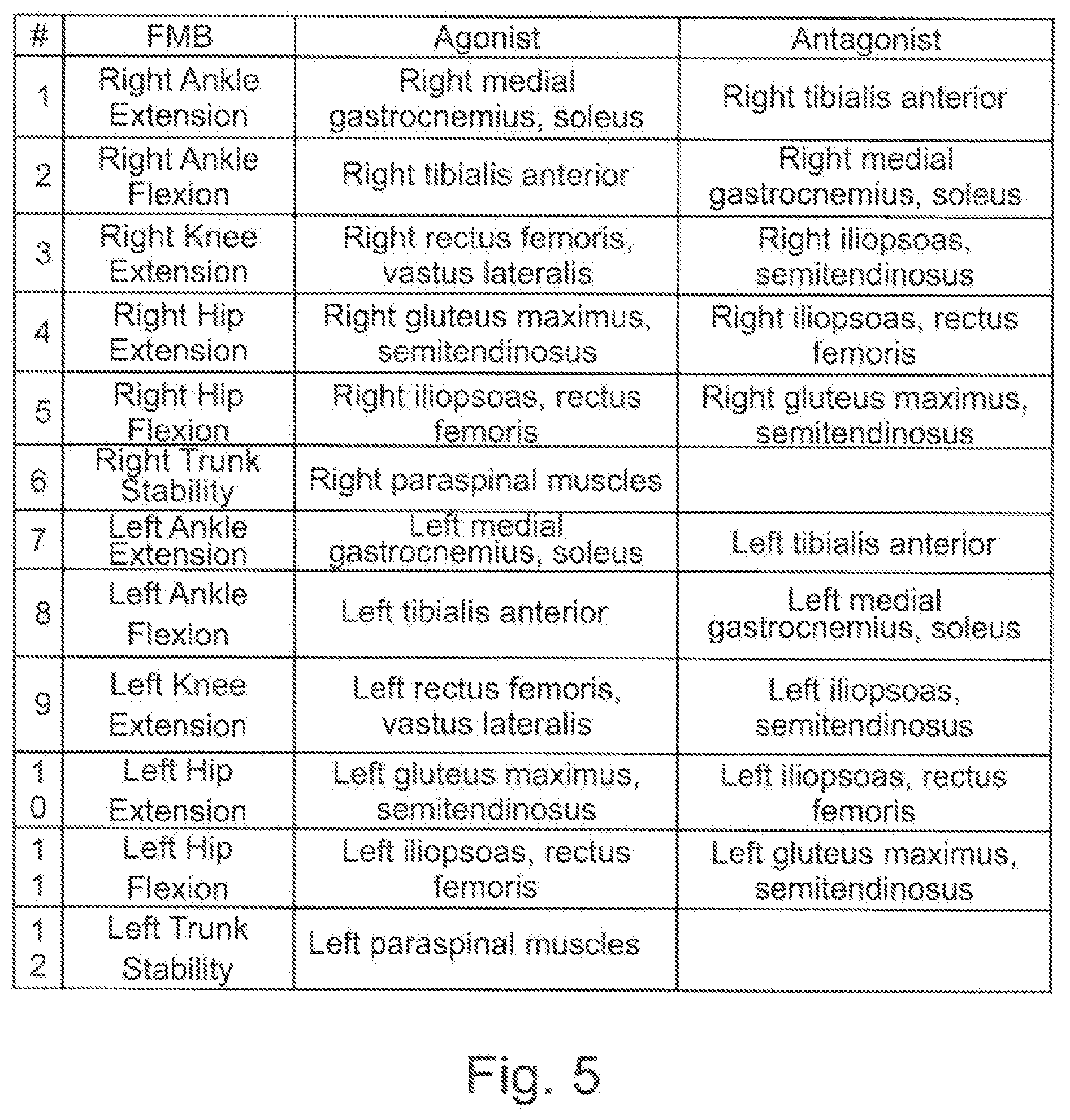
[0091] FIG. 5 a table specifying the intended movement and the involved agonist muscle and the involved antagonist muscle;
[0092] FIG. 6 functional muscle blocks (FMB) and custom muscle blocks (CMB);
[0093] FIG. 7 a general layout of an embodiment of the control system for a movement reconstruction and/or restoration system for a patient P according to the present invention;
[0094] FIG. 8A a perspective view of a patient equipped with the control system disclosed in FIG. 7 comprising two sensors according to the present invention;
[0095] FIG. 8B a perspective view of a patient equipped with the control system disclosed in FIG. 7 comprising seven sensors;
[0096] FIG. 8C a perspective view of a sensor insole according to the present invention;
[0097] FIG. 8D a perspective view of a patient equipped with the control system disclosed in FIG. 7 comprising one IMU and one pressure insole for each foot according to the present invention; and
[0098] FIG. 9 a schematical diagram of food pitch/forward acceleration of a patient P equipped with the control system disclosed in FIG. 7.
DETAILED DESCRIPTION
[0099] Note that in the following we primarily refer to CNS/EES stimulation. The one skilled in the art may transfer the stimulation parameters to PNS/FES stimulation.
[0100] The control system may provide stimulation data for movement reconstruction and/or restoration for stimulation of afferent nerve fibers using electrical current pulses. Given this starting point, the following stimulation parameters may be identified:
[0101] Electrode configuration (which electrodes to use, polarity)
[0102] Stimulation (Pulse) amplitude
[0103] Stimulation (Pulse) width
[0104] Stimulation (Pulse) frequency
[0105] FIG. 1 illustrates a schematic, very simplified representation of the stimulation pulse, which illustrates the pulse amplitude, pulse width, and pulse frequency. Each stimulation pulse is followed by a neutralization pulse or a neutralization period (not depicted) to remove the electric charge from the tissue in order to avoid tissue damage.
[0106] The effects of each of the stimulation parameters are described below.
[0107] Electrode configuration: Stimulating a specific muscle group requires applying a specific electrical field at a specific location on the spinal cord or directly through stimulation of motorfibers (neuro-muscular stimulation), or through a limited set reflexes or by transcutaneously stimulating peripheral nerves. Therefore, in the present control system, the electrical stimulation may be delivered e.g. to the spinal cord by a lead with multiple electrodes. The location, shape, and direction of the electrical field that is produced may be changed by choosing a different electrode configuration (which electrodes are used, with which polarity and potential) that is used to deliver the current. Hence, the electrode configuration may determine to which spinal roots the stimulation is delivered, and therefore which subsequent muscles or muscle groups activity will be reinforced.
[0108] Pulse amplitude and pulse width: In FIG. 2A and FIG. 2B the necessary current and necessary charge to trigger an action potential in a nerve fiber are shown as a function of the pulse width (using a square pulse) (cf: Merrill D R. et al., Electrical Stimulation of excitable tissue: design of efficacious and safe protocols, J Neurosci methods 141(2):171-98 (2005)). FIG. 2A and FIG. 2B also show the rheobase current I.sub.rh, which is the current that is required when using infinitely long pulse widths, and the chronaxie time t.sub.c, which is the required pulse width at a current of 2I.sub.rh.
[0109] Although larger currents may be required at smaller pulse widths, the total required charge may decrease with decreasing pulse width, see FIG. 2B. Hence shorter pulses with higher current amplitudes may be energetically beneficial.
[0110] For smaller diameter nerves, the current-pulse width curve of FIG. 2A shifts, as smaller diameter fibers may require higher currents. Hence, a higher current may activate more nerve fibers, as also smaller diameter nerve fibers may be activated (until saturation). However, also cross-talk is increased as also more neurons from neighboring roots may be activated. Fortunately, the afferent fibers involved in motor control (fiber types Ia and Ib) may be all relatively large (12-20 .mu.m), while the fibers involved in touch, temperature, and pain feedback (which should not be triggered) may be relatively small (0.5-12 .mu.m), as depicted in FIG. 3. Hence, with increasing pulse width and/or current amplitude, the type Ia and Ib fibers may be the first to be recruited. This may enable recruiting (most of) the relevant fibers while keeping cross-talk and patient discomfort to a minimum.
[0111] Pulse frequency: The pulse frequency may determine the frequency of the action potentials generated in the afferent nerves, assuming sufficient charge is delivered each pulse to trigger the action potentials. As no new action potential can occur in a nerve during the refractory period, the frequency of the triggered action potentials will saturate at high pulse frequencies. This saturation point is generally at around 200 Hz for afferent fibers (Miller J P. et al., Parameters of Spinal Cord Stimulation and Their Role in Electrical Charge Delivery: A Review. Neuromodulation: Technology at the Neural Interface 19, 373-384, (2016)). However, stimulation at frequencies above the saturation point may still be beneficial, as by increasing frequency the total charge delivered per unit time (i.e. charge per second) can be increased without changing current amplitude or pulse width (Miller J P. et al., Parameters of Spinal Cord Stimulation and Their Role in Electrical Charge Delivery: A Review. Neuromodulation: Technology at the Neural Interface 19, 373-384, (2016)).
[0112] Pulse positioning: Many tasks, including walking, require simultaneous activation of multiple muscle groups. Hence, to support these tasks, multiple muscle groups may need to be stimulated simultaneously, each requiring a specific electrical field and pulse frequency. When applied simultaneously, these different electrical fields may interact with each other, potentially leading to unintended and uncontrolled effects. Therefore, to avoid this situation, care should be taken that the individual stimulation pulses and their neutralization periods targeting different muscle groups are not applied simultaneously. This may not be considered a stimulation parameter but does identify a required system feature: a pulse positioning algorithm.
[0113] The previous section describes the effect of the stimulation parameters on triggering action potentials in afferent nerve fibers. Although triggering these action potentials is an essential step in the therapy, in the end the stimulation should enable or support the patient in performing specific lower body motions, which may require the activation of specific muscles or muscle groups. The effect of the triggered action potentials in afferent nerve fibers on muscle activation may be filtered inside the spinal cord through spinal reflex circuits and modulated through the voluntary control of the patient. Hence, the effect of the stimulation parameters on muscle activation may be not perfectly clear and may be affected by intra- and inter-Patient variations. The following aspects may be of relevance here:
[0114] Different patients may have different levels of voluntary control over their lower body, depending on the type and severity of their SCI lesion level and state of (spontaneous) recovery.
[0115] Stimulation of afferent nerve fibers may assist or enable activation of the corresponding muscles but may not necessarily enforce motion. The patient may modulate the activation (e.g. make a large or small step without changing the stimulation), or even resist motion of the leg completely. This may vary per patient and may change with increasing recovery.
[0116] Conjecture: Because the spinal cord floats in the cerebrospinal fluid, the distance between the spinal cord and the Lead electrodes may vary (mostly as a function of the Patient's posture: prone--large distance, supine--small distance). Another hypothesis may be that due to posture changes, the layer thickness of low conductive epidural fat between the Lead electrodes and the dura/cerebrospinal fluid a changing, leading to an impedance change as seen by the electrodes, and resulting in an altered current/voltage delivered stimulation by the electronics. As a result, the effect of the applied stimulation (including muscle onset and saturation) may also vary with the patient's posture. Although this conjecture is not proven, patients may successfully make use of the described effects to modulate the stimulation intensity by varying their posture: bending forward reduces the intensity, bending backward increases it.
[0117] Pulse frequencies between 40 and 120 Hz may mostly being used, although it may theoretically be possible to stimulate up to 500 Hz as this may have benefits for selectivity in muscle activation and improved voluntary control of the patient.
[0118] It may be possible that generally increasing the pulse amplitude may not lead to increased recruitment of muscle fibers (with corresponding increased cross-talk), and that increasing the stimulation frequency may lead to increased muscle activation without affecting cross-talk. However, increasing the stimulation frequency may reduce the intensity of natural proprioception and result in a decreased feeling in the leg of the patient. This is probably due to the collision of natural sensory inputs with antidromic action potentials generated by the electrical stimulation. At high frequency (above 100 Hz), patients may even report a complete loss of sensation of the leg and "feel like walking with their legs being absent". This is a non-comfortable situation requiring the patient to make a leap of faith at each single step, believing that the leg that he/she does not feel anymore will support him/her during the next stance phase. Adjusting the balance between stimulation amplitude and frequency may therefore be necessary to find the optimal compromise between cross-talk limitation and loss of sensation. Simulations suggest that a possible workaround may be to shift the stimulation domain to lower amplitudes and even higher frequency, such that with a minimal number of stimulated fibers the same amount of activity is triggered in the spinal cord. Such hypothesis requires validation via additional clinical data. Finally, it may also be identified that different patients require different stimulation, i.e. that the optimal frequency and amplitude settings can may vary highly between patients. Hence, the relation between stimulation amplitude and frequency on muscle activation may be still for a large part unclear. Moreover, the optimal stimulation settings may vary during the day, the assistive device that is used (crutches, walker, etc.), over time with improved recovery, and with the goal of the training or activity.
[0119] Timing: Apart from applying the correct electrical field at the right location on the spinal cord, they also may need to be applied at the correct moments in time and correctly sequenced. The relevant timing aspects that are identified are listed below.
[0120] There is a delay from stimulation on the spinal cord to muscle activation (typical values in the order of 0-30 ms depending on the muscle, see FIG. 4, LVLat=left vastus lateralis, RVLat=right vastus lateralis, Lll=left iliopsoas, Rll=right iliopsoas, LRF=left rectus femoris, RRF=right rectus femoris, LST=left semitendinosus, RST=right semidentinosus, LTA=left tibialis anterior, RTA=right tibialis anterior, LMG=left medial gastrocnemius, RMG=right medial gastrocnemius, LSol=left soleus, RSol=right soleus, LFHL=left flexor halluces longus, RFHL=right flexor halluces longus).
[0121] While EES enables patients to perform motions, the patient may need to be able to predict when the stimulation will occur in order to make the best use of the stimulation. Likewise, suppressing motion while stimulation is provided also requires that the patient knows when to expect the stimulation. Hence, predictability of the stimulation timing is essential.
[0122] When the stimulation is not synchronized to the patient's (intended) motion, the patient may not be able to perform a proper movement. Here, this may mean that the stimulation needs to be predictable by the patient, as the patient needs to synchronize to the stimulation.
[0123] The duration of the stimulation for leg swing during walking may need to be finely tuned. For some patients, increasing the duration of this stimulation by 100 ms made the patient jump instead of performing a proper step.
[0124] 20 ms may be a sufficient resolution for tuning the stimulation timings (i.e. the on/off times of the stimulation for a specific muscle group may not need to be controlled at a precision below 20 ms). Given current data availability, controlling the timings at resolutions below 20 ms may not seem to improve the effectiveness of the stimulation.
[0125] Based on the previous sections, the stimulation parameters may be selected to control in the control system. This may determine the control output space that is used, and therefore the complexity of the control problem and the potential effectiveness of the control system.
[0126] First it is discussed which parameter spaces can be reduced or eliminated. The remaining control output space is summarized below.
[0127] Electrode configuration: Walking, as well as other movements of the lower extremities, may be composed of well-coordinated flexion and extension of lower body joints by contraction of agonist muscles and relaxation of antagonist muscles. The specific set of agonist and antagonist muscles for joint specific flexion and extension may be grouped, and as the number of joints is limited, this means that only a small discrete set of muscle groups may be needed to be stimulated. For each joint flexion and extension, the Space Time Programmer (STP, for e.g. programming space and time of the stimulation) will support creating the optimal electrode configuration for activation of the agonist muscles while avoiding activation of the antagonist muscles (as well as avoiding activation of muscles on the contralateral side). This may be done in a procedure called the functional mapping. We define the Functional Muscle Blocks (FMB), as the resulting stimulation configurations for each specific muscle group. At least 12 specific FMBs have been identified for using the control system, these are listed in FIG. 5 with their corresponding agonists and antagonists.
[0128] As knee flexion and hip extension both involve the semitendinosus, it is physically not possible to target knee flexion and hip extension separately. Therefore, FIG. 5 does not include Knee Flexion (this could be considered redundant to Hip Extension).
[0129] Next to the 12 FMB listed in FIG. 5, it is also envisioned that the trainer/therapist/physiotherapist may create Custom Muscle Blocks (CMB). Creating CMB may be useful in case the trainer/therapist/physiotherapist wants to apply stimulation that does not specifically target any of the 12 muscle groups targeted by the FMB, or in case the trainer/therapist/physiotherapist wants to use a variant of one of the 12 FMB in a specific task.
[0130] Hence, by limiting the electrode configurations to the discrete set of FMB and CMB (versus an infinite number of possible electrode configurations), the control problem complexity may be reduced considerably without significantly affecting the potential effectiveness of the control system. Stimulation for a task is then reduced to stimulation of (a subset of) the predefined FMB and CMB, see FIG. 6. For this example, the Right Trunk Stability is used in both Task 1 and Task 2.
[0131] The functional mapping procedure may require measuring the response of each of the muscles listed in FIG. 5 with EMG sensors. Due to the large number of muscles, this requires attaching many EMG sensors to the patient (which is time consuming) and processing a large amount of data. Moreover, as motion of the patient may induce signal artifacts, the functional mapping may be best performed while the patient is not moving. For these reasons, the functional mapping procedure may be performed in a separate session using the space time programmer, e.g. for programming of space and time of stimulation, and not e.g. adaptively within the control system. Hence, the configuration of FMB and CMB may be considered as a given to the control system.
[0132] Pulse width: From the viewpoint of triggering action potentials in afferent nerve fibers, the parameters pulse width and pulse amplitude may be tightly linked and may together determine which afferent nerve fibers are recruited. Increasing the pulse width may allow to reduce the amplitudes and decreasing the pulse width may allow reducing energy consumption (as the total required charge for triggering an action potential decreases with decreasing pulse width, see FIG. 2B and stimulating more FMB simultaneously or at higher frequencies. However, from a control perspective the two parameters may be (almost) redundant, as increasing either parameter may lead to the recruitment of more afferent nerve fibers over a larger area.
[0133] Pulse widths below chronaxie time t.sub.c may quickly require high currents (and thus high voltages), which is difficult to produce and may lead to patient discomfort. Beyond t.sub.c, the strength-duration curve of FIG. 2A is almost flat, so increasing pulse width beyond t.sub.c has little effect on the required amplitudes while it increases total power consumption. Also considering that having a fixed pulse width simplifies the pulse positioning, the pulse width is chosen to be fixed (at a value near chronaxie time t.sub.c such that both energy consumption and required current amplitudes remain low, where t.sub.c.apprxeq.200 .mu.s for afferent dorsal root nerve fibers in humans). This reduces the complexity of the control problem by reducing the number of output parameters.
[0134] This may leave the following stimulation parameters to be controlled over time by the control system:
[0135] Which FMBs to stimulate
[0136] Stimulation amplitude per FMB
[0137] Stimulation frequency per FMB
[0138] The pulse positioning may be considered a lower level problem and may therefore be not a direct output of the control system (system feature). The pulse positioning may be performed by the IPG.
[0139] Although combining amplitude and frequency to a single `intensity` parameter has been considered, doing so may not be envisioned for the control system, as these parameters may have very different effects. On triggering action potentials in afferent nerve fibers, the amplitude and frequency may be independent parameters: the amplitude determines in which afferent nerve fibers action potentials are triggered, the frequency determines the rate at which they are triggered. Hence, in principle the amplitude determines which muscle fibers are activated, the frequency determines how hard, although it is unclear if the independence of the two parameters also holds for muscle activation due to the signal processing that occurs in the spinal cord. Moreover, it may be apparent that for some patients changing the amplitude gives the best results, while for other patients the frequency may be the more useful parameter.
[0140] As we do not know the precise relation between frequency and amplitude in the clinical context it cannot be recommended to combine frequency and amplitude to single parameter, until more data is available. Hence, the stimulation frequency and amplitude will be controlled independently from each other.
[0141] In the following the stimulation system (e.g. IPG), the controller and the sensor of the present invention are described in greater detail.
[0142] Stimulation system, here IPG: Implantable Pulse Generator. A battery powered device that generates the electrical stimulation, subcutaneously implanted. Its intended use is to deliver electrical stimulation to the Lead based on command received from the controller.
[0143] Controller: Battery powered, body worn device (directly or indirectly), receiving data from sensor(s) and able to send stimulation commands to the IPG for specific tasks (i.e. an activity/training exercise). Its intended use is to determine optimal stimulation settings for any given task and providing this information to the IPG. In addition, this device can take the IPG out of shelf mode, charge the IPG battery transcutaneous, and initiate an IPG-Lead integrity test.
[0144] Sensors: Battery powered, body worn sensors (directly or indirectly), collecting motion data, and sending it to the controller. Its intended use is to capture body motion parameters.
[0145] The control system may further comprise a programmer: The programmer, or also called the clinician programmer, can be used to receive inter alia stimulation parameter, patient data, physiological data, training data etc.
[0146] It may comprise a Space Time Programmer (STP) for e.g. programming space and time of the stimulation, a Physiotherapist Programmer (PTP) for e.g. allowing the physiotherapist adjustment to the stimulation, and a Patient Programmer (PP) for e.g. allowing the patient to select a specific stimulation program.
[0147] The Space Time Programmer (STP), Physiotherapist Programmer (PTP), and Patient Programmer (PP) can be embodied as applications installed on a mobile device that communicate with the controller. They are used by the treating physician (TP), a physiotherapist (PT), or the Patient to provide inputs to the controller, e.g., selecting, starting, and stopping a task or configuring stimulation parameters.
[0148] The Programmer can allow adjusting the stimulation parameters of a task, while the task is running. This enables the user to tune the stimulation without having to start and stop the task, which would be very cumbersome at the start of the rehabilitation training, when all stimulation partitures are developed and tuned.
[0149] Generally speaking, the programmer may have the following structure:
[0150] In a first embodiment, the programmer can be embodied such that it is possible to receive inter alia but not limited to stimulation parameters, patient data and the like, check and/or reprogram the stimulation data and send it back to e.g. the controller.
[0151] The programmer is in this first embodiment capable to receive data from the implanted (part of the) system (e.g. the controller), display data, receive input from the user and then send it back to the controller. In other words: The programmer can receive, process and re-send the data.
[0152] In a second embodiment, the programmer may receive data from a remote database. The database may be e.g. linked with the stimulation system via a separate interface, which is configured for data transfer from the system to the database only.
[0153] The programmer is in this second embodiment capable to receive data from the remote database, display data, receive input from the user and then send it to the controller. In other words: The programmer is only in connection with the controller for sending data, it does not receive data from the controller or any implanted system parts.
[0154] FIG. 7 shows a general layout of an embodiment of the control system 10 for a movement reconstruction and/or restoration system for a patient P according to the present invention.
[0155] The control system 10 comprises at least one sensor 12.
[0156] Furthermore, the control system 10 comprises in the shown embodiment a controller 14.
[0157] Additionally, the control system 10 comprises a CNS-Stimulation Module 30 for CNS-Stimulation.
[0158] In this embodiment, the CNS-Stimulation Module 30 is a EES-Module 30 for EES.
[0159] The EES-Module 30 comprises an implantable pulse generator (IPG) 18.
[0160] The EES-Module further comprises a lead 20.
[0161] The lead 20 comprises a lead cable.
[0162] The lead 20 further comprises an electrode module 22.
[0163] The electrode module 22 comprises one or more electrodes.
[0164] Additionally, the control system 10 comprises a PNS-Stimulation Module 40 for PNS-Stimulation.
[0165] In this embodiment, the PNS-Stimulation Module 40 is a FES-Module 40 for FES.
[0166] The FES-Module 40 comprises an IPG 18.
[0167] The FES-Module 40 further comprises a lead 20.
[0168] The lead 20 comprises a lead cable.
[0169] The lead 20 further comprises an electrode module 22.
[0170] The electrode module 22 is configured and arranged to stimulate the locomotor system of the patient.
[0171] The electrode module 22 comprises one or more electrodes.
[0172] The one or more sensors 12 is/are connected to the controller 14.
[0173] The connection between the one or more sensors 12 and the controller 14 is in the shown embodiment a direct connection.
[0174] However, also an indirect connection (i.e. with another component of the control system 10 in between) would be generally possible.
[0175] The connection between the one or sensors 12 and the controller 14 is established in the shown embodiment via a wireless network WSN.
[0176] However, also a cable-bound connection would be generally possible.
[0177] The controller 14 is connected to the IPGs 18 in the shown embodiment via a direct connection.
[0178] However, also an indirect connection (i.e. with another component of the control system 10 in between) would be generally possible.
[0179] The connection between the controller 14 and the IPG 18 of the EES-Module 30 is established in the shown embodiment via a wireless link TEL.
[0180] The connection between the controller 14 and the IPG 18 of the FES-Module 40 is established in the shown embodiment via a wireless link TEL.
[0181] However, also a cable-bound connection would be generally possible.
[0182] The IPG 18 of the EES-Module 30 is connected to the lead 20 of the EES-Module 30 via a direct connection.
[0183] The IPG 18 of the FES-Module 40 is connected to the lead 20 of the FES-Module 40 via a direct connection.
[0184] However, also an indirect connection could be possible.
[0185] In one embodiment, the controller 14 is body-worn, the IPG 18 is implanted in the body, and the one or more sensors 12 is/are directly attached to at least one of the patient's limbs or to a training entity, e.g. a bicycle crank.
[0186] However, also an indirect attachment could be generally possible.
[0187] By means of the one or more sensors 12 signals indicative for a motion, e.g. movement of a limb, e.g. an arm or leg, or a foot or hand, can be sensed and used by the control system 10.
[0188] The sensor signals are transferred to the controller 14 and there processed.
[0189] The controller 14 processes data that is from e.g. the sensor 12 and the IPG 18.
[0190] By means of the controller 14 the control software is executed.
[0191] The controller 14 controls the CNS-Stimulation Module 30, i.e. the EES-Module 30.
[0192] The controller 14 controls the PNS-Stimulation Module 40, i.e. the FES-Module 40.
[0193] In this embodiment, the controller 14 adapts the stimulation provided by the CNS-Stimulation Module 30 and/or the PNS-Stimulation Module 40 on the basis provided by the sensor 12
[0194] The controller 14 programs the IPG 18 to deliver the correct stimulation via the lead 20 and the electrode module 22.
[0195] In this embodiment, the controller 14 programs the IPG 18 of the EES-Module 30 to deliver EES via the lead 20 and the electrode module 22.
[0196] In general, the electrodes of the electrode module 22 are configured and arranged to stimulate the patient locomotor system, especially wherein the at least one electrode is attached to and/or arranged at a limb and/or part of a limb and/or a foot and/or the CNS and/or spinal circuits, in particular dorsal roots.
[0197] For EES, here the lead 20 is positioned in the epidural space (i.e. on the outside of the dural sac, which encases the spinal cord and the cerebrospinal fluid in which the spinal cord `floats`), on top of the spinal cord (including but not limited to the segments T12, L1, L2, L3, L4, L5, and S1 bilaterally).
[0198] In this embodiment, the controller 14 programs the IPG 18 of the FES-Module 40 to deliver FES via the lead 20 and the electrode module 22.
[0199] In this embodiment, FES is provided directly through stimulation of motorfibers (neuro-muscular stimulation).
[0200] Alternatively, FES could be provided by or through a limited set of reflexes (practically limited to the withdrawal reflex) or by transcutaneous stimulation of the peripheral nerves.
[0201] It is also possible that the control system 10 comprises only one IPG 18 for both EES and FES.
[0202] In other words, it is also possible that the control system 10 comprises only one IPG 18 which is shared by the EES-Module 30 and the FES-Module 40.
[0203] It is also possible that the control system 10 comprises only one IPG 18, in particular only for EES.
[0204] It is also possible that the control system 10 comprises only one IPG 18, in particular only for FES.
[0205] Alternatively, also other suitable stimulation signals may be provided.
[0206] Not shown in FIG. 7 is that the at least one sensor 12 is an inertial measurement unit (IMU).
[0207] Said IMU comprises an accelerometer, a gyroscope, and a magnetometer.
[0208] Said IMU measures and reports 3D accelerations, 3D angular velocities and 3D orientation using a combination of an accelerometer and a gyroscope.
[0209] In an alternative embodiment, an IMU could use a combination of one or more of an accelerometer, one or more gyroscopes, and optionally one or more of a magnetometer.
[0210] By integrating the angular velocity assessed by the gyroscope and fusing with data from the accelerometers, a precise measurement of the angle of the foot is obtained. Based on these measurements the orientation of the IMU 12 with respect to the fixed world is estimated accurately, using standard sensor fusion algorithms.
[0211] So, movement is detected and therefrom also a signal derived, which is indicative for an angle, e.g. the foot angle.
[0212] Real-time and non-real-time reconstruction of foot trajectories may be done up to a few centimeters accuracy.
[0213] In this embodiment, real-time is defined as an end-to-end latency that is less than 100 ms, preferably less than 50 ms.
[0214] In an alternative embodiment, the at least one sensor 12 could also be one of an optical sensor, a camera, a piezo element, a velocity sensor, an accelerometer, a magnetic sensor, a torque sensor, a pressure sensor, a displacement sensor, an EMG measurement unit, a goniometer, a hall sensor, a gyroscope and/or a motion tracking video camera, or a infra-red camera.
[0215] Some sensors 12 could require fixed base station in the environment, including but not limited to magnet sensors or infra-red sensors.
[0216] Electromagnetic position sensors, optical sensors and cameras could estimate 3D position and orientation.
[0217] Torque sensors could be placed on a bicycle crank for assessing the torque during cycling.
[0218] Some sensors 12 could be worn by the patient without acquiring fixed base station, including but not limited to piezo elements, pressure sensors and/or torque sensors.
[0219] By directly and/or indirectly attaching one or more sensors 12, e.g. IMUs 12, to the trunk and/or waist and/or head and/or neck and/or at least one limb and/or one or more parts of a limb, including one or more joints, the angular velocity and angle of the trunk and/or head and/or neck and/or at least one limb and/or one or more parts of a limb during motion, e.g. gait cycle could be determined to realize the reorganization of the various motion phases, e.g. gait phase.
[0220] Thanks to the angle it could be possible to compute the acceleration of the limb and/or part of the limb in the forward direction.
[0221] However, also acceleration in any other direction may theoretically be determined.
[0222] In particular, the angle of the ankle joint varies during gait cycle with different gait events (including but not limited to toe-off, midswing, heel strike, foot flat and midstance, heel-off).
[0223] The angular velocity and angle of the trunk and/or head and/or neck and/or at least one limb and/or one or more parts of a limb of a patient P could be used to predict the intended and/or ongoing motion.
[0224] The angle of at least one limb and/or part of a limb can also be used to find out which support the patient really needs from the control system 10.
[0225] For open loop walking, e.g. a change in limb angle and/or part of a limb angle (including joints, e.g. ankle joint) over a certain threshold could be used to initiate a certain stimulation sequence.
[0226] In particular, the gait event heel-off could trigger the stimulation for one or more complete gait cycles.
[0227] However, also other gait events, including but not limited to toe-off, midswing, heel strike, foot flat and midstance could trigger stimulation for one or more complete gait cycles.
[0228] Note that also single events of other periodic movements could trigger the stimulation for one or more complete motion cycles.
[0229] In other words, the control system 10 is not only applicable for walking/gait cycle, but also for other movements, including but not limited to cycling, swimming, stepping, rowing, sitting down, standing up, squatting, etc.
[0230] Two or more sensors 12 could form a sensor network, cf. also FIG. 8B.
[0231] In an alternative embodiment, the control system 10 could be connected to a training entity via a wireless link.
[0232] Not shown in FIG. 7 is the fact that the one or more sensors 12 could be connected to, inserted and/or integrated in a training entity, included but not limited to an exoskeleton, a body weight support, a treadmill and/or crutches.
[0233] Not shown in FIG. 7 is that for closed-loop cycling, measuring the pedal phase can simply be achieved by attaching a sensor, e.g. an IMU, to the crank of the bicycle or to the food (or both feed) of the patient.
[0234] The foot position, and thus the pedal position, varies during the crank cycle.
[0235] For example, at low pedaling frequencies (up to 85 rpm), the heel is lowered, and the toes slightly raised when pushing, while the toes point downwards when pulling.
[0236] These angles could be reflected in the position of the pedal.
[0237] The pedal phase could then be defined as the crank angle, which is directly linked to the IMU orientation.
[0238] Note that the pedal phase could also be predicted given the current crank angle and angular velocity (both directly provided by placing an IMU on a bicycle crank).
[0239] For closed-loop cycling, the stimulation partiture defines spatial stimulation, at which pedal phase, amplitudes, and frequencies.
[0240] In an alternative embodiment the training entity could also be the patient himself or herself.
[0241] It is possible that the controller 14 tracks and/or estimates a training entity movement for translating it into stimulation data, based on the estimated movement, being provided by the IPG 18 to the patient for the patient training.
[0242] Not shown in FIG. 7 is that the control system 10 could comprise a pre-warning module, which is configured and arranged to provide a pre-warning signal indicative of providing an upcoming stimulation event.
[0243] In particular, the pre-warning signal may act in a sub-motor threshold region at which a sensation is evoked, but not a motor response.
[0244] It is also not shown in FIG. 7 that a pulse generator could generally also be a non-implantable pulse generator.
[0245] It is also not shown in FIG. 7 that remote control of the control system 10 could be generally possible.
[0246] It is also not shown in FIG. 7 that the control system 10 could further comprise or could be linked to a programmer.
[0247] The programmer could be used to receive inter alia stimulation parameter, patient data, physiological data, training data etc.
[0248] The programmer could comprise a Space Time Programmer (STP) for e.g. programming space and time of the stimulation, a Physiotherapist Programmer (PTP) for e.g. allowing the physiotherapist adjustment to the stimulation, and a Patient Programmer (PP) for e.g. allowing the patient to select a specific stimulation program.
[0249] The Space Time Programmer (STP), Physiotherapist Programmer (PTP), and Patient Programmer (PP) could be embodied as applications installed on a mobile device that communicate with the controller.
[0250] They could be used by the treating physician (TP), a physiotherapist (PT), or the Patient to provide inputs to the controller, e.g., selecting, starting, and stopping a task or configuring stimulation parameters.
[0251] The programmer could allow adjusting the stimulation parameters of a task, while the task is running.
[0252] This enables the user to tune the stimulation without having to start and stop the task, which would be very cumbersome at the start of the rehabilitation training, when all stimulation partitures are developed and tuned.
[0253] Generally speaking, the programmer could have the following structure:
[0254] In one embodiment, the programmer could be embodied such that it is possible to receive inter alia but not limited to stimulation parameters, patient data and the like, check and/or reprogram the stimulation data and send it back to e.g. the controller.
[0255] The programmer could in this first embodiment be capable to receive data from the implanted (part of the) system (e.g. the controller), display data, receive input from the user and then send it back to the controller.
[0256] In other words: the programmer could receive, process and re-send the data.
[0257] In another embodiment, the programmer could receive data from a remote database.
[0258] The database could be e.g. linked with the stimulation system via a separate interface, which could be configured for data transfer from the system to the database only.
[0259] The programmer in this second embodiment could be capable to receive data from the remote database, display data, receive input from the user and then send it to the controller.
[0260] In other words: the programmer could be only in connection with the controller for sending data, it could does not receive data from the controller or any implanted system parts.
[0261] FIG. 8A shows a perspective view of a patient P equipped with the control system disclosed in FIG. 7 comprising two sensors according to the present invention.
[0262] In this embodiment, a patient P is equipped with said control system 10 disclosed in FIG. 7 comprising two sensors 12, which are here two IMUs 12a attached to the shoes S of the patient P.
[0263] In particular, one IMU 12a is attached to the left shoe S of the patient P and one IMU 12a is attached to the right shoe S of the patient P.
[0264] In this embodiment, the IMUs 12a are placed on the heel area of the shoes S of the patient P.
[0265] In this embodiment, the control system 10 comprises also two electrodes 22a for FES.
[0266] In particular, one electrode 22a for FES is attached to the left leg of the patient P and one electrode 22a for FES is attached to the right leg of the patient P.
[0267] However, it could be generally possible that each leg of the patient P is equipped with two or more electrodes 22a for FES.
[0268] In particular, one electrode 22a for FES is attached to the left upper leg of the patient P and one electrode 22a for FES is attached to the right upper leg of the patient P.
[0269] However, it could be generally possible that the one or more electrodes 22a for FES are placed at any other position(s) of the legs of the patient P.
[0270] Further, in this embodiment, the control system 10 comprises one electrode 22b for EES.
[0271] The electrode 22b for EES is attached to the dorsal roots of the patient P.
[0272] However, also positioning two or more electrodes 22b for EES to the dorsal roots, in the epidural space, or on top of the spinal cord could be generally possible.
[0273] In general, each limb could be targeted and/or targetable with at least one electrode 22a and/or 22b.
[0274] In other words, each limb could be targeted by one or more electrodes 22b for EES and/or one or more electrodes 22a for FES.
[0275] According to FIG. 7, by means of the two IMUs 12a attached to each shoe S of the patient P each movement of the left foot and right foot of the patient P is sensed and used by the control system 10.
[0276] The controller 14 tracks and/or estimates the movement of the foot of the patient P for translating it into stimulation data, based on the estimated movement, being provided by the IPG 18 to the patient P.
[0277] The IPG 18 provides FES via the lead 20 and the electrode module 22 with the one or more electrodes 22a.
[0278] The IPG 18 provides EES via the lead 20 and the electrode module 22 with the one or more electrodes 22b.
[0279] In an alternative embodiment, one sensor 12 may be arranged at each limb of a patient.
[0280] In an alternative embodiment, the IMUs 12a could be placed at and/or inserted in, and/or in different positions in the shoe S or in the shoe sole and/or in the shoe insole.
[0281] In an alternative embodiment, the control system 10 could comprise only one IMU 12a positioned directly or indirectly to the left foot or the right foot, or the left shoe S or the right shoe S of the patient P.
[0282] Alternatively, a patient equipped with the control system 10 disclosed in FIG. 7 could be equipped with two or more sensors 12 for at least one limb, cf. also FIG. 8B.
[0283] In particular, at least one sensor 12 could be inserted and/or arranged in the shoe S and/or into the sole and/or into the insole 100 of a shoe S of a patient.
[0284] Said sensors 12 may be positioned at any place from the distal end to the proximal end of the foot, in particular in the heel area and/or the metatarsal area and/or the toe area, and/or the sides of the feet.
[0285] In an alternative embodiment, the one or more sensor(s) 12 could be inserted and/or integrated into and/or onto an exoskeleton, tights, a belt, straps, a stretching band, a knee sock, a sock and/or a shoe S of the patient.
[0286] However, in general it could also be possible that socks and/or tights consist of and/or comprise a piezoelectric textile sensor integrated in the trunk, waist, hip, knee, heel, toe area.
[0287] An electrical response according to a mechanical stretching, pressing or pulling could be delivered.
[0288] In particular, socks and/or tights could be equipped with electrodes and/or electro conductive yarn.
[0289] Alternatively, magnetic sensors and magnetic field sensors could be incorporated in shoes S for walking on a magnetic sensor plate or inserted in the treadmill or gait phase detection device.
[0290] The magnetic force could be detected and acquired by magnetic sensors under gait training.
[0291] Not shown in FIG. 8A is that for assessing upper body motion and/or arm motion and/or hand motion, the one or more sensors 12 could be inserted and/or integrated into and/or onto clothing or the like for the upper body and/or arms, and or hands, including but not limited to a top, a longsleeve, a pullover, aj acket, one or more arm sleeves, gloves, and/or one or more armlets.
[0292] Not shown in FIG. 8A is that the electrodes 22a/22b could also be configured and arranged for limb cramp stimulation to release cramp and/or detection of limb cramp.
[0293] Not shown in FIG. 8A is that stimulating motion of one or more limbs and/or one or more parts of a limb does not necessarily require stimulating on the locomotor system of one or more limbs and/or one or more parts of the limb, respectively, directly.
[0294] As just one example, the spinal cord or the upper leg may be stimulated to induce a reflex and/or motion of the foot.
[0295] FIG. 8B shows a perspective view of a patient equipped with the control system disclosed in FIG. 7 comprising seven sensors.
[0296] In this embodiment, a patient P is equipped with said control system 10 disclosed in FIG. 7 comprising seven sensors 12, which are here seven IMUs 12a.
[0297] The seven IMUs 12a build a sensor network 12c.
[0298] In this embodiment, the seven IMUs 12a are attached to the lower body of the patient P.
[0299] In particular, one IMU 12a is placed centrally in the hip area, whereas the left leg is equipped with three IMUs 12a placed on the foot, the lower leg, and the upper leg, and whereas the right leg is equipped with three IMUs 12a, placed on the foot, the lower leg, and the upper leg, respectively.
[0300] However, also alternative placements of a different number of IMUs 12a along the legs and/or feet and/or the lower body could be generally possible.
[0301] According to FIG. 7, by means of the seven IMUs 12a placed on the lower body of the patient P each movement of the legs and feet of the patient P is sensed and used by the control system 10.
[0302] According to FIG. 8B, both FES and EES can be provided by the IPG 18, the lead 20 and the electrode module 22 with respective electrodes 22a and 22b.
[0303] Not shown in FIG. 8B is that any part of the body of a patient, including but not limited to the limbs, the trunk, the abdomen, the head and/or the neck could be equipped with at least one sensor network 12c comprising at least two sensors for measuring any type of body movement.
[0304] FIG. 8C shows a perspective view of a sensor insole according to the present invention.
[0305] In this embodiment, according to the control system 10 disclosed in FIG. 7, various sensors 12 are integrated into a sensor insole 100 for a shoe S of a patient.
[0306] In this embodiment, the sensors 12 are pressure sensors 12b.
[0307] In particular, eight pressure sensors 12b are incorporated in a sensor insole 100 for a shoe S of a patient P.
[0308] In particular, the eight pressure sensors 12b are distributed from the distal end di of a sensor insole 100 to the proximal end pr of a sensor insole 100 for a shoe S of a patient.
[0309] In particular, the eight pressure sensors 12b are distributed along the heel area, the metatarsal area, and the toe area of the sensor insole 100.
[0310] In particular, two pressure sensors 12b are placed in the heel area, two pressure sensors 12b are placed in the toe area and four pressure sensors 12b are placed in the metatarsal area of the sensor insole 100.
[0311] In general, both shoes S of a patient P could be equipped with sensor insoles 100.
[0312] The sensor insoles 100 provide a precise map of the foot force.
[0313] In particular, the pressure sensors 12b in the sensor insole 100 provide a precise description of the gait phase and cadence, swing, stance, toe-off, midswing, heel strike, flat foot, midstance and/or heel-off can be identified for one foot by analyzing sensor data obtained from one sensor insole 100 of a shoe S.
[0314] The same events and parameters can be identified for the other foot of the patient P by using a second sensor insole 100.
[0315] By combining signals of sensor insoles 100 of both feet of a patient P, together with the gait phase and cadence of the stimulation input, a reliable gait phase and cadence estimate can be provided.
[0316] The sensor stream is transmitted to the controller 14 according to the disclosure of FIG. 7.
[0317] In one embodiment, alternative placements of the eight pressure sensors 12b in a sensor insole 100 could be possible.
[0318] However, it could be also possible that 1-7 or more than 8 pressure sensors 12b are integrated in a sensor insole 100 of a shoe S of a patient P.
[0319] It could also be possible that the sensor insole 100 itself is a pressure sensor 12b.
[0320] FIG. 8D shows a perspective view of a patient equipped with the control system disclosed in FIG. 7 comprising one IMU and one pressure insole for each foot of the patient according to the present invention.
[0321] In this embodiment, a patient P is equipped with the control system 10 disclosed in FIG. 7 including one IMU 12a placed on the left shoe S and one IMU 12a placed on the right shoe S of a patient P as disclosed in FIG. 8A and one sensor insole 100 as disclosed in FIG. 8C for the left shoe S of the patient P and one sensor insole 100 as disclosed in FIG. 8C for the right shoe of the patient P.
[0322] Accordingly, the sensor insoles 100 for both shoes of the patient P comprise eight pressure sensors 12b (only exemplarily shown in FIG. 8D).
[0323] Alternatively, a patient P could be equipped with the control system 10 described in FIG. 7 including one IMU 12a and one respective sensor insole 100 for the left or the right foot.
[0324] In another embodiment, the IMU and/or the sensor insole can be replaced by another type of sensor 12 including but not limited to e.g. a piezo element.
[0325] In this embodiment, it could be possible that the piezo element is integrated in wearables like e.g. a sock, a knee sock, tights, a shoe.
[0326] Note that the example control and estimation routines included herein can be used with various system configurations. The control methods and routines disclosed herein may be stored as executable instructions in non-transitory memory and may be carried out by a control system 10 e.g. as a part of the controller 14 in combination with the sensors 12, the EES-Module 30 and/or he FES-Module 40, and other system hardware. The specific routines described herein may represent one or more of any number of processing strategies such as event-driven, interrupt-driven, multi-tasking, multi-threading, and the like. As such, various actions, operations, and/or functions illustrated may be performed in the sequence illustrated, in parallel, or in some cases omitted. Likewise, the order of processing is not necessarily required to achieve the features and advantages of the example embodiments described herein but is provided for ease of illustration and description. One or more of the illustrated actions, operations and/or functions may be repeatedly performed depending on the particular strategy being used. Further, the described actions, operations and/or functions may graphically represent code to be programmed into non-transitory memory of a computer readable storage medium in the controller 14, where the described actions are carried out by executing the instructions in a control system 10 including the various hardware components.
[0327] FIG. 9 shows a schematic diagram of food pitch/forward acceleration of a patient P equipped with the control system disclosed in FIG. 7.
[0328] Here, the patient P is equipped with one IMU 12a per foot.
[0329] Alternatively, the patient P could be equipped with the control system 10 described in FIG. 7 including one IMU 12a and one respective sensor insole 100 for the left or the right foot.
[0330] In another embodiment, the patient could be equipped with two or more IMUs 12a per foot.
[0331] Further, the IMU 12a and/or the sensor insole 100 can be replaced by another type of sensor 12 including but not limited to e.g. a piezo element.
[0332] In this embodiment, it could be possible that the piezo element is integrated in wearables like e.g. a sock, a knee sock, tights, a shoe.
[0333] The foot pitch (degree) and forward acceleration (meter per s.sup.2) of the right foot of a patient P equipped with the control system 10 disclosed in FIG. 7 during walking is shown.
[0334] From these signals, clearly the cadence, pre-swing, swing, loading response and stance can be identified.
[0335] The same events and parameters can be identified for the left foot.
[0336] As walking is a periodic motion, all measured signals are also periodic.
[0337] By combining gait phase and cadence information of both feet of the patient together with the gait phase and cadence of the stimulation input, a reliable gait phase and cadence estimate can be provided.
[0338] Note that gait can vary a lot between different patients P as well as for a single patient P for different walking speeds and different assistive devices (body-weight support, walker, crutches, etc.).
[0339] Especially for impaired gait, not all gait events are always present.
[0340] Hence, it is always possible to estimate the cadence by extracting the base frequency of the measured signals.
[0341] Moreover, machine-learning methods can be used to adapt the gait phase estimation to the specific gait of the patient P.
[0342] The level of agreements and discrepancies between motion of the left and right foot, and the stimulation input, can be used to give an indication of the gait phase estimation reliability, e.g., the measured cadence of the left foot should be equal to the measured cadence of the right foot and the cadence of the provided stimulation, and the left foot and right foot should be (roughly) in anti-phase.
[0343] In the control loop also use can made of the realization that the feet do not move independently from each other but are connected mechanically via the hip and on neural level via the spinal cord.
[0344] In particular, inhibitory reflex circuits in the spinal cord modulate neural firing rates (and hence modulate recruitment of motor neurons through EES).
[0345] Note that the example control and estimation routines included herein can be used with various system configurations. The control methods and routines disclosed herein may be stored as executable instructions in non-transitory memory and may be carried out by a control system 10 e.g. as a part of the controller 14 in combination with the one or more sensors 12, the IPG 18, the lead 20, and other system hardware. The specific routines described herein may represent one or more of any number of processing strategies such as event-driven, interrupt-driven, multi-tasking, multi-threading, and the like. As such, various actions, operations, and/or functions illustrated may be performed in the sequence illustrated, in parallel, or in some cases omitted. Likewise, the order of processing is not necessarily required to achieve the features and advantages of the example embodiments described herein but is provided for ease of illustration and description. One or more of the illustrated actions, operations and/or functions may be repeatedly performed depending on the particular strategy being used. Further, the described actions, operations and/or functions may graphically represent code to be programmed into non-transitory memory of a computer readable storage medium in the controller 14, where the described actions are carried out by executing the instructions in a control system 10 including the various hardware components.
REFERENCES
[0346] 10 control system [0347] 12 sensor [0348] 12a inertial measurement unit (IMU) [0349] 12b pressure sensor [0350] 12c sensor network [0351] 14 controller [0352] 18 implantable pulse generator (IPG) [0353] 20 lead [0354] 22 electrode module [0355] 22a electrode for FES [0356] 22b electrode for EES [0357] 30 CNS-Stimulation Module, EES-Module [0358] 40 PNS-Stimulation Module, FES-Module [0359] 100 sensor insole [0360] pr proximal region of the foot or insole [0361] di distal region of the foot or insole [0362] P Patient [0363] S Shoe [0364] CMB custom muscle blocks [0365] EES Epidural Electrical Stimulation [0366] FES Functional Electrical Stimulation [0367] FMB functional muscle block [0368] WL wireless link [0369] WSN wireless network, connection [0370] TEL connection, telemetry line [0371] LVLat left vastus lateralis [0372] RVLat right vastus lateralis [0373] Lll left iliopsoas [0374] Rll right iliopsoas [0375] LRF left rectus femoris [0376] RRF right rectus femoris [0377] LST left semitendinosus [0378] RST right semidentinosus [0379] LTA left tibialis anterior [0380] RTA right tibialis anterior [0381] LMG left medial gastrocnemius [0382] RMG right medial gastrocnemius [0383] LSol left soleus [0384] RSol right soleus [0385] LFHL left flexor halluces longus [0386] RFHL right flexor halluces longus
* * * * *
D00000
D00001
D00002
D00003
D00004
D00005
D00006
D00007
D00008
D00009
D00010
D00011
D00012

XML
uspto.report is an independent third-party trademark research tool that is not affiliated, endorsed, or sponsored by the United States Patent and Trademark Office (USPTO) or any other governmental organization. The information provided by uspto.report is based on publicly available data at the time of writing and is intended for informational purposes only.
While we strive to provide accurate and up-to-date information, we do not guarantee the accuracy, completeness, reliability, or suitability of the information displayed on this site. The use of this site is at your own risk. Any reliance you place on such information is therefore strictly at your own risk.
All official trademark data, including owner information, should be verified by visiting the official USPTO website at www.uspto.gov. This site is not intended to replace professional legal advice and should not be used as a substitute for consulting with a legal professional who is knowledgeable about trademark law.