Apparatus, System, And Method For Painting A Human Nail
GRIFFON; Alexandre Pierre
U.S. patent application number 16/183771 was filed with the patent office on 2020-05-14 for apparatus, system, and method for painting a human nail. The applicant listed for this patent is Alexandre Pierre GRIFFON. Invention is credited to Alexandre Pierre GRIFFON.
| Application Number | 20200146419 16/183771 |
| Document ID | / |
| Family ID | 70552045 |
| Filed Date | 2020-05-14 |
| United States Patent Application | 20200146419 |
| Kind Code | A1 |
| GRIFFON; Alexandre Pierre | May 14, 2020 |
APPARATUS, SYSTEM, AND METHOD FOR PAINTING A HUMAN NAIL
Abstract
A nail painting machine, a cartridge for painting human nails is provided, and a method for painting human nails using a nail polish machine containing a nail polish cartridge therein is provided. The nail painting machine comprising a casing, the casing having an opening-closing means configured to open the casing to access a cartridge receiving portion and to close the casing to enclose the cartridge receiving portion; a positioning assembly disposed inside the casing including at least one motor, wherein the cartridge receiving portion is rotatably attached to the positioning assembly; and an operation assembly disposed inside of the casing having at least one positioning detector, and an ECU configured to communicate with the positioning assembly, and at least one positioning detector.
| Inventors: | GRIFFON; Alexandre Pierre; (PARIS, FR) | ||||||||||
| Applicant: |
|
||||||||||
|---|---|---|---|---|---|---|---|---|---|---|---|
| Family ID: | 70552045 | ||||||||||
| Appl. No.: | 16/183771 | ||||||||||
| Filed: | November 8, 2018 |
| Current U.S. Class: | 1/1 |
| Current CPC Class: | A45D 34/042 20130101; A45D 2034/005 20130101; A45D 29/14 20130101; A46B 2200/1046 20130101; A46B 9/021 20130101 |
| International Class: | A45D 29/14 20060101 A45D029/14; A46B 9/02 20060101 A46B009/02; A45D 34/04 20060101 A45D034/04 |
Claims
1. A nail painting machine for painting human nails, the nail painting machine comprising: a casing, the casing having an opening-closing means configured to open the casing to access a cartridge receiving portion and to close the casing to enclose the cartridge receiving portion; a positioning assembly disposed inside the casing including at least one motor, wherein the cartridge receiving portion is rotatably attached to the positioning assembly; and an operation assembly disposed inside of the casing having at least one positioning detector and an ECU configured to communicate with the positioning assembly and at least one positioning detector.
2. The nail painting machine of claim 1, wherein the positioning assembly includes: a first motor affixed to a first rack, the first rack being slideably attached to a first guide allowing the positioning apparatus to move in a first direction along a first axis; a second motor affixed to a second rack, the second rack being slideably attached to a second guide allowing the positioning apparatus to move in a second direction along a second axis; and a third motor affixed to a third rack, the third rack being slideably attached to a third guide allowing the positioning apparatus to move in an third direction along a third axis.
3. The nail painting machine of claim 2, wherein a fourth motor is affixed to a fourth rack and is rotatably attached to the cartridge receiving portion, the cartridge receiving portion being rotatable about at least one of the first, second, and/or third axes.
4. The nail painting machine of claim 1, wherein the operation assembly further includes a cartridge actuator attached to the cartridge receiving portion.
5. The nail painting machine of claim 4, wherein the ECU is further configured to communicate with the cartridge actuator.
6. The nail painting machine of claim 1, wherein the ECU is configured to: receive an image from at least one position detector; determine a position of at least one nail; determine a contour of the at least one nail; determine a trajectory for the positioning assembly based on the contour and position of the at least one nail; and command the positioning assembly to execute the determined trajectory.
7. The nail painting machine of claim 1, wherein the cartridge receiving portion is configured to receive a cartridge.
8. The nail painting machine of claim 1, further including a second position detector, wherein the ECU is further configured to determine a curvature of the at least one nail using the second position detector.
9. A cartridge for painting human nails, the cartridge comprising: a container having at least two openings, the container having nail polish therein; a plunger disposed in one of the at least two openings and is sideably attached to the container; and an applicator, wherein the cartridge is adapted to expel the liquid nail polish onto the applicator when the plunger is engaged.
10. The cartridge of claim 9, wherein the cartridge is adapted to be inserted into a cartridge receiving portion of a nail painting machine.
11. The cartridge of claim 9, wherein the applicator is a brush.
12. The cartridge of claim 9, wherein the applicator is a fin.
13. The cartridge of claim 9, wherein the container includes a tube extending outwardly therefrom and substantially parallel to the applicator, the tube being adapted to channel nail polish therethrough and onto the applicator.
14. The cartridge of claim 9, wherein the container includes an inner wall and an outer wall having a gap therebetween, the inner wall defining a plurality of openings, the plurality of openings being adapted to channel nail polish therethrough and onto the applicator, wherein the plunger is retractable inside the inner wall.
15. A method for painting human nails using a nail polish machine containing a nail polish cartridge therein, the method comprising the steps of: receiving an image from the position detector; determining a position of at least one nail; determining a contour of the at least one nail; determining a trajectory for a positioning assembly bearing the nail polish cartridge of the nail polish machine based on the contour and position of the at least one nail; commanding a cartridge actuator of the nail polish machine to engage a plunger of the nail polish cartridge and expel nail polish from the cartridge; and commanding the positioning assembly to execute the determined trajectory.
16. The method of claim 15, further including the step of acquiring the curvature of the at least one nail.
17. The method of claim 15, wherein when determining the trajectory, an applicator of the cartridge engages the nail, thereby applying nail polish onto the nail.
18. The method of claim 17, wherein the applicator is moved along the nail from a proximate, first position to a distal, second position.
19. The method of claim 17, wherein the cartridge is rotated about an axis when executing the determined trajectory.
20. The method of claim 15, the method further including activating a dryer.
Description
FIELD OF THE DISCLOSURE
[0001] The present disclosure is related to an automated machine that is able to paint a human nail.
BACKGROUND OF THE DISCLOSURE
[0002] The desire to paint one's nails has been popular for centuries, dating back to 3000 B.C. After the tech boom of the 1980's, the integration of electronics as a matter of convenience and efficiency became increasingly popular, including machines that are capable of performing nail art. In 1999, Japanese company Atlus launched a nail art machine labeled "NailMore." Subsequently, other companies launched similar nail art printing machines, for example, Plenty Inc. launched their "Nail Art Club Machine" in 2003, and Mattel launched their "Barbie Dolled Up Nail Printer" in 2009. Each one of the above mentioned machines uses a method of printing an inkjet pattern on a human nail that has been previously treated with an ink receptive nail polish. The major drawbacks for these machines it that they can be complicated, expensive, time consuming, and bulky.
SUMMARY OF THE DISCLOSURE
[0003] The present inventor has recognized is that it is desirable to provide a machine that is less expensive, less time consuming, compact, and further has the capability to treat the nail with nail polish rather than have the user paint the nail prior to using the device. Additionally, the inventor has recognized the need for the device to receive consumable cartridges that can contain various types and colors of nail painting liquid.
[0004] According to embodiments of the present disclosure, a nail painting machine for painting human nails is provided. The nail painting machine comprises a casing, the casing having an opening-closing means configured to open the casing to access a cartridge receiving portion and to close the casing to enclose the cartridge receiving portion; a positioning assembly disposed inside the casing including at least one motor, wherein the cartridge receiving portion is rotatably attached to the positioning assembly; and an operation assembly disposed inside of the casing having at least one positioning detector, and an ECU configured to communicate with the positioning assembly, and at least one positioning detector.
[0005] In aspects, the positioning assembly of the nail painting machine may include a first motor affixed to a first rack, the first rack being slideably attached to a first guide allowing the positioning assembly to move in a first direction along a first axis, a second motor affixed to a second rack, the second rack being slideably attached to a second guide allowing the positioning assembly to move in a second direction along a second axis, and a third motor affixed to a third rack, the third rack being slideably attached to a third guide allowing the positioning to move in an third direction along a third axis.
[0006] In aspects, the nail painting machine may also include a fourth motor that is affixed to a fourth rack and is rotateably attached to the cartridge receiving portion, the cartridge receiving portion may be rotatable about at least one of the first, second, and/or third axes. In aspects, the operation assembly may further include a cartridge actuator attached to the cartridge receiving portion.
[0007] In aspects, the ECU of the nail painting machine may be configured to communicate with the cartridge actuator. In aspects, the ECU may be configured to receive an image from the position detector; determine a position of at least one nail; determine a contour of the at least one nail; determine a trajectory for the positioning assembly based on the contour and position of the at least one nail; and command the positioning assembly to execute the determined trajectory. In aspects, the cartridge receiving portion of the nail machine may be configured to receive a cartridge.
[0008] A cartridge for painting human nails is provided. The cartridge may comprise a container having at least two openings, the container having nail polish therein; a plunger disposed in one of the at least two openings and may be sideably attached to the container; and an applicator. The cartridge may be adapted to expel the liquid nail polish onto the applicator when the plunger is engaged.
[0009] In aspects, the cartridge may be adapted to be inserted into a cartridge receiving portion of a nail painting machine. In aspects, the applicator may be a brush. In other aspects, the applicator may be a fin. In aspects, the container may include a tube extending outwardly therefrom and substantially parallel to the applicator, the tube may be adapted to channel nail polish therethrough and onto the applicator.
[0010] In aspects, the container may include an inner wall and an outer wall having a gap therebetween, the inner wall defining a plurality of openings, the plurality of openings may be adapted to channel nail polish therethrough and onto the applicator, wherein the plunger may be retractable inside the inner wall.
[0011] A method for painting human nails using a nail polish machine containing a nail polish cartridge therein is provided. The method may comprise the steps of: receiving an image from the position detector; determining a position of at least one nail; determining a contour of the at least one nail; determining a trajectory for a positioning assembly bearing the nail polish cartridge of the nail polish machine based on the contour and position of the at least one nail; commanding a cartridge actuator of the nail polish machine to engage a plunger of the nail polish cartridge and expel nail polish from the cartridge; and commanding the positioning assembly to execute the determined trajectory.
[0012] In aspects, when executing the determined trajectory, an applicator of the cartridge may engage the nail, thereby applying nail polish onto the nail. In aspects, the applicator may be moved along the nail from a proximate, first position to a distal, second position, while performing the method. In aspects, the cartridge may be rotated about an axis when executing the determined trajectory. In aspects, the method may further include activating a dryer.
[0013] It is intended that combinations of the above-described elements and those within the specification may be made, except where otherwise contradictory.
[0014] The accompanying drawings, which are incorporated in and constitute a part of this specification, illustrate embodiments of the disclosure and together with the description, and serve to explain the principles thereof.
BRIEF DESCRIPTION OF THE DRAWINGS
[0015] FIG. 1 shows an isometric view of an exemplary nail painting machine;
[0016] FIG. 2A shows a cross-section of an exemplary cartridge with a plunger in a first position;
[0017] FIG. 2B shows a cross-section of a variation of the exemplary cartridge in a second position;
[0018] FIG. 3A shows an isometric view of another exemplary cartridge in a first position;
[0019] FIG. 3B shows the exemplary cartridge of FIG. 3A in a second position;
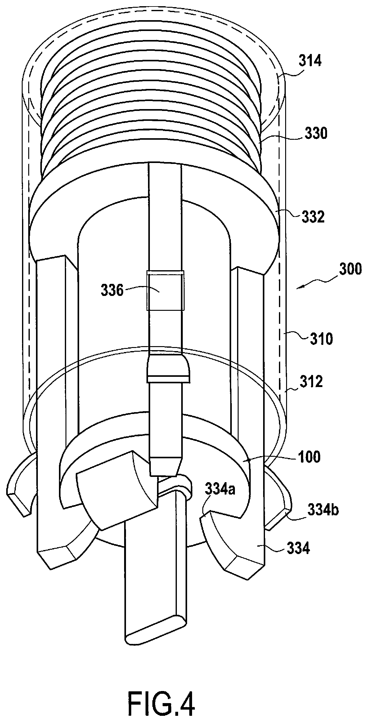
[0020] FIG. 4 shows an isometric view of an exemplary cartridge within a cartridge receiving portion;
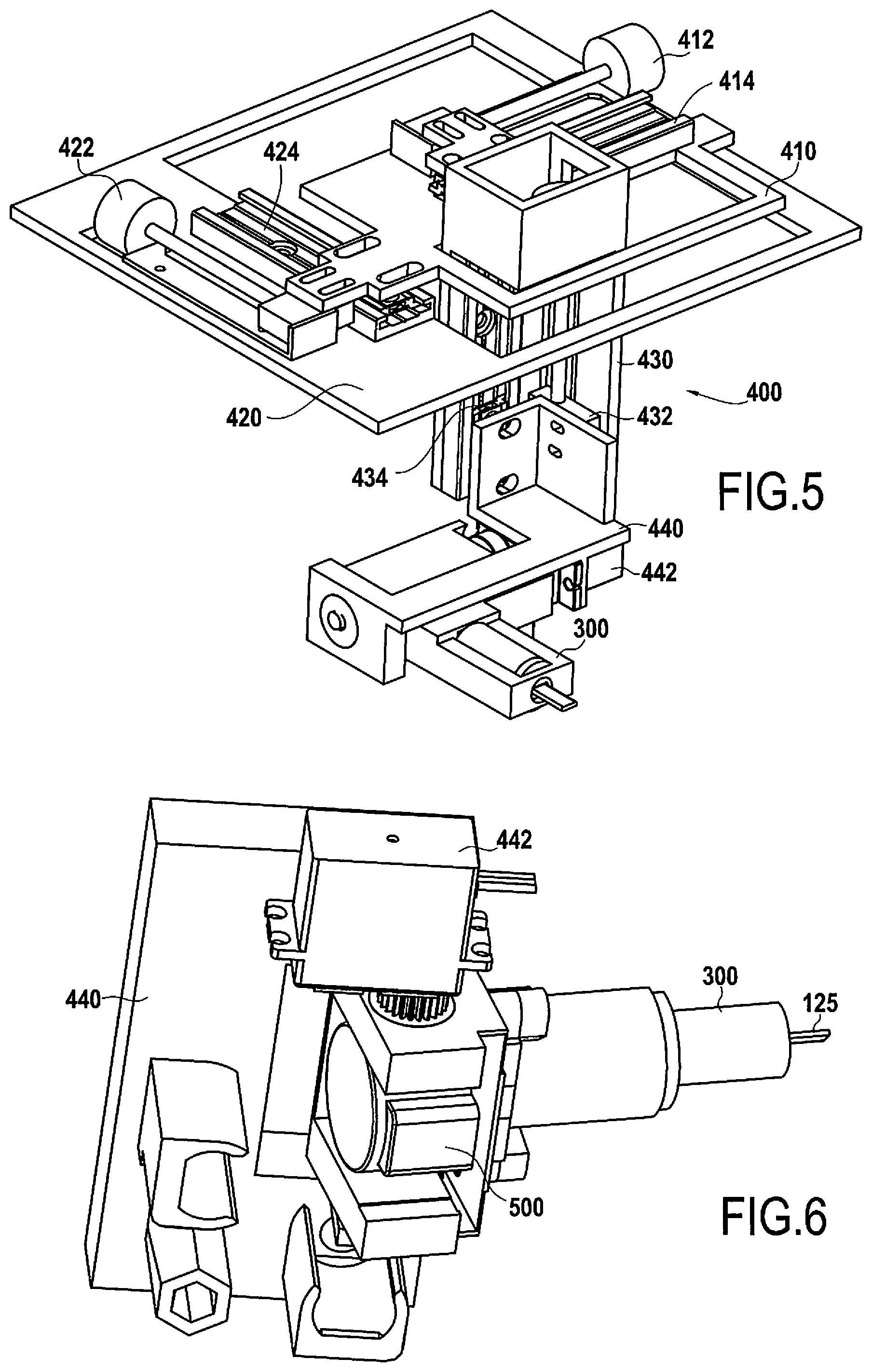
[0021] FIG. 5 shows a top isometric view of an exemplary positioning assembly having an exemplary cartridge therein;
[0022] FIG. 6 shows a bottom isometric view of the exemplary positioning assembly of FIG. 5;
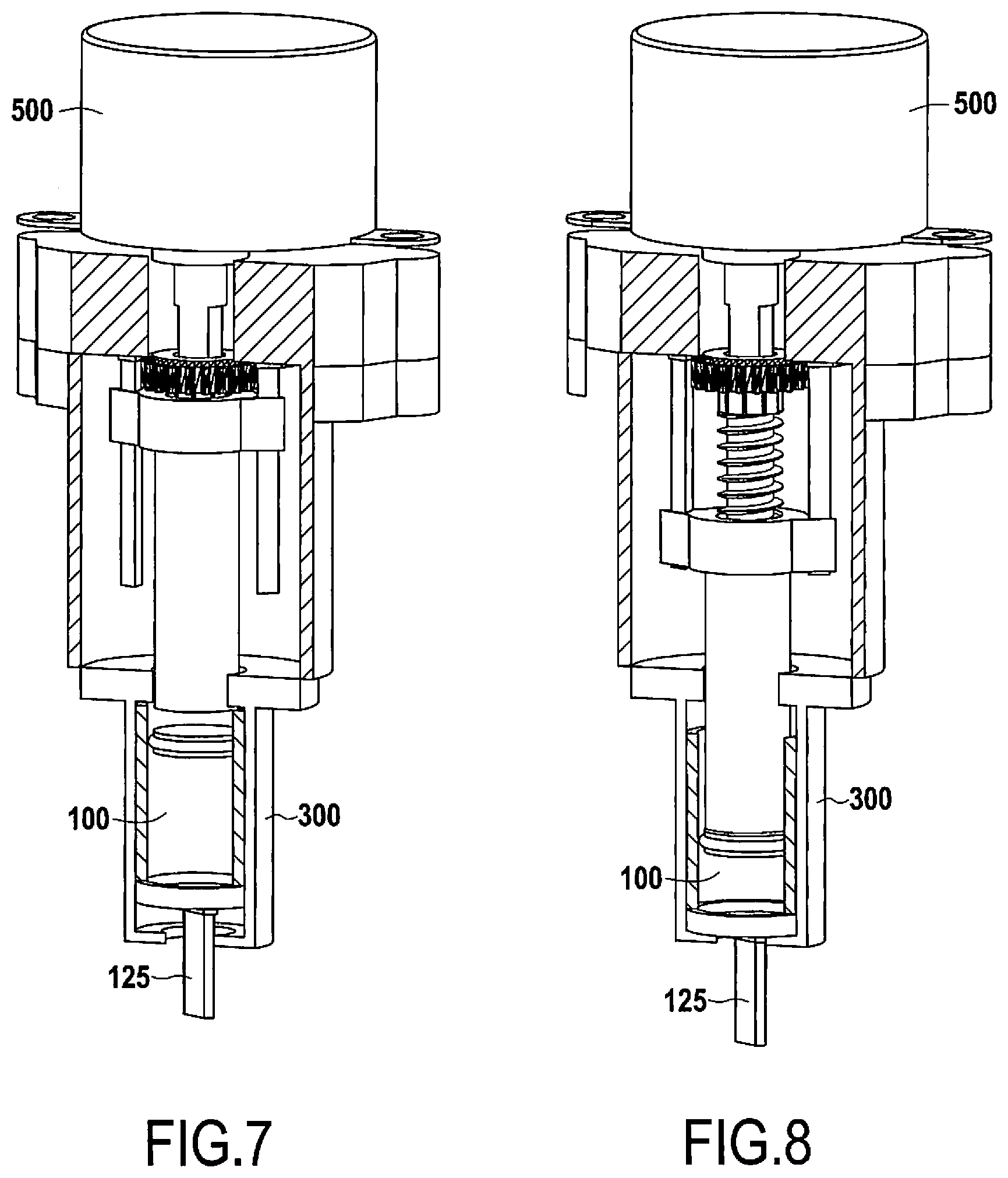
[0023] FIG. 7 shows an exemplary cartridge actuator in a first position, the cartridge actuator being attached to a cartridge receiving portion having the exemplary cartridge therein; and
[0024] FIG. 8 shows the exemplary cartridge actuator of FIG. 7 in a second position.
DESCRIPTION OF THE EMBODIMENTS
[0025] Reference will now be made in detail to exemplary embodiments of the disclosure, examples of which are illustrated in the accompanying drawings. Wherever possible, the same reference numbers will be used throughout the drawings to refer to the same or like parts.
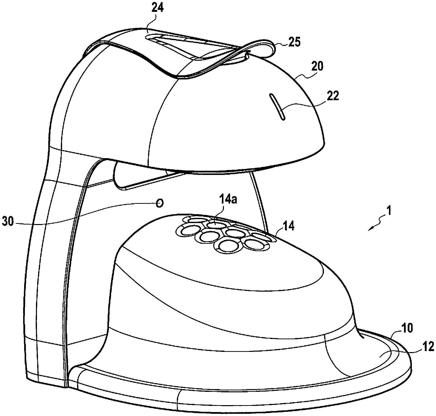
[0026] FIG. 1 shows an isometric view of an exemplary nail painting machine 1. The nail painting machine 1 has a base 10. The base may include a run-off channel 12 and a hand receiving portion 14. As can be seen in FIG. 1, the hand receiving portion 14 may be a protuberance, having a bulbous shape. However, the hand receiving portion 14 of the nail painting machine 1 is not limited to a bulbous shape, and may be any other suitable shape. The hand receiving portion 14 may define at least one finger receiving area 14a.
[0027] As shown in FIG. 1, the hand receiving portion 14 may define a plurality of circular shaped depressions, which is the finger receiving area 14a. However, it is contemplated that the finger receiving area 14a may be a channel or any other suitable shape. The hand receiving portion 14 may be composed of a durable and non-slip surface, for example, rubber. The surface may be textured. The base 10 may be composed of one type of material or may be composed of different materials. For example, the hand receiving portion 14 may be a rubber sheet, the run-off channel 12 may be a metal plate, and the remainder of the base 10 may be a polymer.
[0028] The nail painting machine 1 further includes a casing 20, which may include at least one sensor 30, an indicator 22, and a lever 24. The at least one sensor 30, which may be a camera, may be positioned facing the hand receiving portion 14 such that it can adequately sense the position and dimensions on the finger nails of the user. For example, the sensor 30 may be positioned in front of the hand and adapted to detect the thickness and the curvature of the finger, or the sensor 30 may be positioned over the hand and is adapted to detect the boundaries of the nail. It is also envisioned that the nail painting machine 1 may further include a second sensor (not shown). For example, the first sensor 30 may be positioned in front of the hand and adapted to detect the thickness and the curvature of the finger and the second sensor may be positioned over the hand and is adapted to detect the boundaries of the nail. However, these are merely examples and the at least one sensor can be located in any suitable place on the nail painting machine 1.
[0029] The indicator 22 may be disposed in a cut-out in the casing 20. The indicator 22 may be an LED and is configured to indicate to a user of the nail painting machine 1 what actions to take. For example, if the indicator shows a green light, it is ready to commence or has finished operation. When the indicator shows a red light, there is an error in the system.
[0030] The casing 20 may be hollow and may contain a cartridge receiving portion 300 and a position assembly 400 therein (shown in FIG. 5). In operation, the lever 24 may be locked when in a flat or first position. The lever may form a lip 25 that is at the distal end thereof. The lip 25 may be disposed such that when the lever is in the first position, the lip 25 is easily accessible to a user of the nail painting machine 1. Additionally, when the lever is in an upright, or second position, the casing 20 may be opened, exposing the cartridge receiving portion 300. In this second position, a user of the nail painting machine 1 is able to insert a cartridge 100, 200 that contains nail painting liquid, into the cartridge receiving portion 300.
[0031] The base 10 and casing 20 may be a monolithic structure, however it is also contemplated that the base 10 may be removably attached to the casing 20.
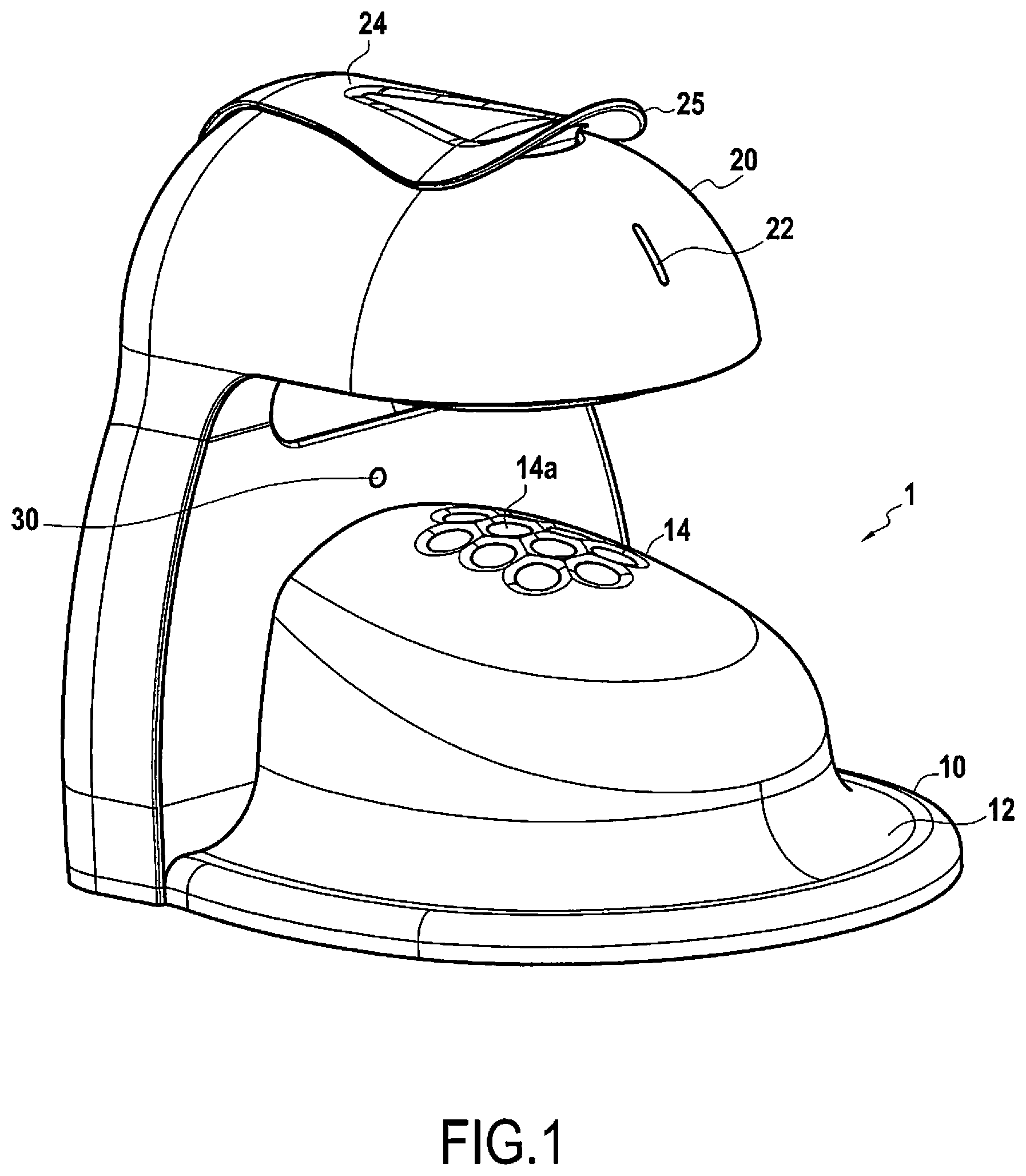
[0032] Turning to FIGS. 2A and 2B which show an exemplary cartridge 100. The cartridge 100 may include a container 110 which has an open first end 112 and an open second end 116. The cartridge may be substantially cylindrical in shape, however, it is also contemplated that the cartridge can be another other suitable shape, for example, a pyramid. In this embodiment, the cartridge 100 may further include a plunger 130, the plunger 130 having a gasket 132 circumscribing the outer surface thereof. The plunger 130 may be adapted to slide from a first position near the second end 116 of the container 110 to a second position near the first end 112 of the container 110.
[0033] Additionally, the cartridge 100 may include an applicator 120 liquidtightly connected to a first end 112 of the container 110. The applicator 120 may have a discharge vent 122, a mount 124, and a pad 125. It is contemplated that the pad may be a brush or a fin or any other suitable means for applying the contents of the cartridge 100.
[0034] The container 110 of the cartridge 100 may be hollow and may be adapted to contain a nail polishing liquid therein. The liquid may be any one of a suitable nail polishing liquid, including but not limited to, shellac, gel, or varnish.
[0035] The gasket 132 of the plunger 130 may be adapted to sealingly engage the inner surface of the container 110 of the cartridge 100. The gasket 132 of the plunger may be composed of rubber, or any other suitable material.
[0036] In operation, when the plunger 130 is moved from the first position to the second position, pressure is applied to any contents within the container 110. The contents are then expelled out of the discharge vent 122 and onto the pad 125 of the applicator. The discharge vent may be formed as an elongated cylindrical body that has an opening on each end. One end of the opening may be adapted to be in communication with any contents that are within the container 110. The other opening may be biased to face the pad 125 such that any contents that are expelled from the container 110 are directed toward the pad 125.
[0037] FIG. 2B is a variation of the exemplary cartridge in FIG. 2A. The cartridge may have a discharge vent 126 that extends along the width of the pad 125. The discharge vent 126 may be formed to have an elongated opening that corresponds with the width of the pad 125 such that the contents that are expelled out of the discharge vent uniformly coats the entire width of the pad 125.
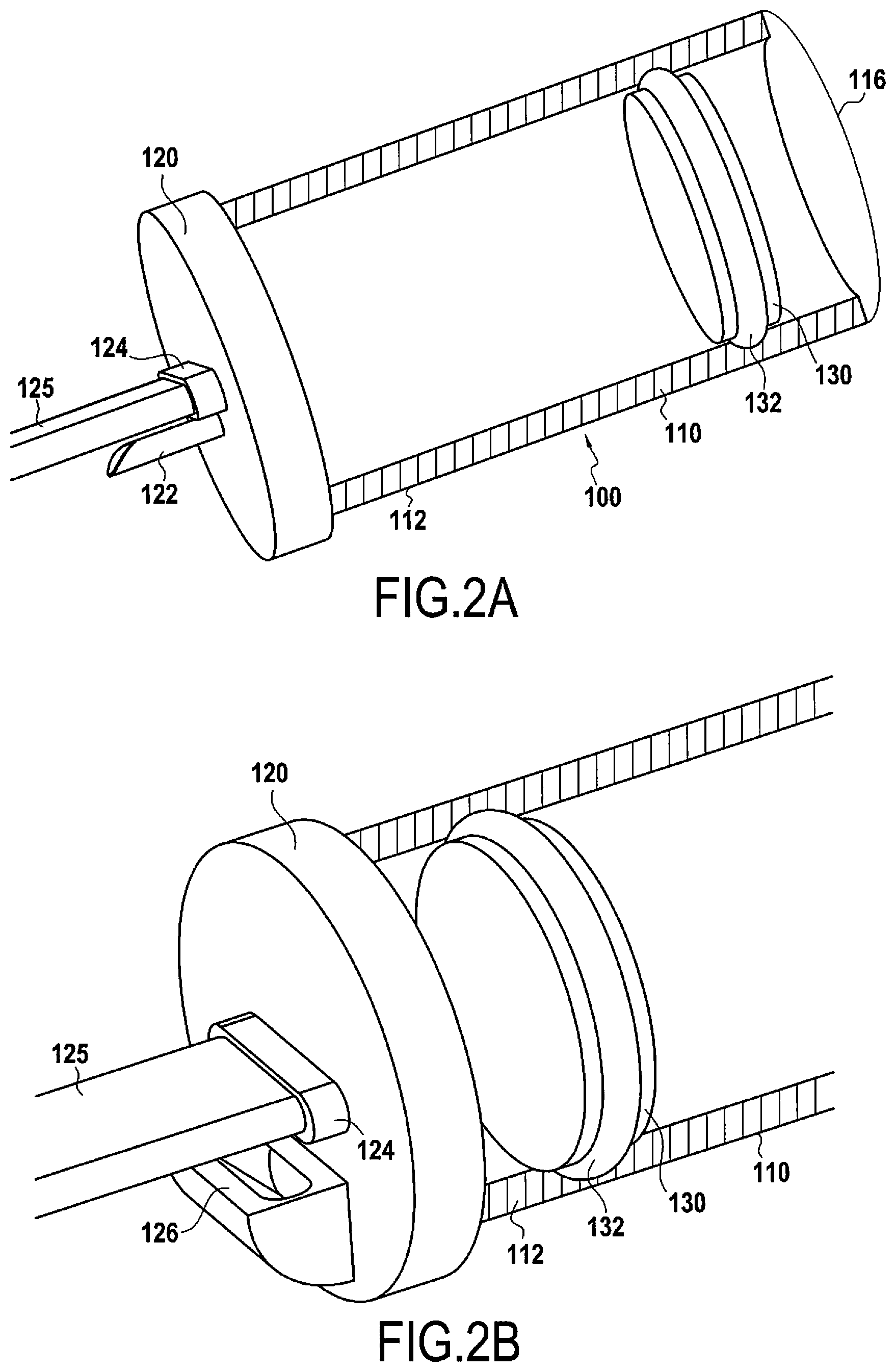
[0038] Turning to FIGS. 3A and 3B, another exemplary cartridge 200 is shown. Cartridge 200 may include a container 210 having a first end 212 and a second end 214. The container may further include a channel 220 extending between the first and second ends 212, 214 and form openings 216, 218. The channel 220 may be partially a solid continuous piece and the remainder is a grate portion 222, which defines holes 224. FIG. 3A shows the grate portion 222 having a plurality of holes, however it is contemplated that the grate portion 222 may have any number of holes therein.
[0039] Container 200 may be a first, retracted position, wherein a plunger 230, spring 232, and applicator 226 may be inside of and disposed within channel 220. The plunger 230 may be sealingly engaged with the grate portion 222 of the channel 220 such that any liquid inside of the container is not expelled out of the opening 216. Positioned between the grate portion 222 and the plunger 230 is the spring 232. When the spring 232 is in an uncompressed position, the plunger 230 and applicator 226 may be retracted into the channel 220 of the container 210. The applicator 226 may be affixed to the end of the shaft of the plunger 230b, on the opposite end of the head of the plunger 230a. While in the retracted position, the applicator 226 may be sealingly engaged with holes 224 such that the contents of the container 210 do not fluidly communicate with opening 218. Thus, in operation, for example, the applicator 226 obtains nail polish when the cartridge 200 is in the retracted position or the spring is in an uncompressed state. In the configuration in FIG. 3A, opening 218 may be obstructed by a seal or removable plug.
[0040] FIG. 3B shows the cartridge 200 in a second, extended position. In this position, the plunger 230 is also in a second position where spring 232 is in a compressed state. Specifically, the shaft of the plunger 230b may be partially extending away from and out of opening 218 such that the applicator 226 is on the exterior of the container 210.
[0041] The terms uncompressed and compressed should not be restricted to meaning a fully uncompressed state or a fully compressed state. The term uncompressed means that the spring is in a more expanded state than when the spring in the compressed state. This also applies to the term compressed state.
[0042] In operation, the cartridge 200 may start in a retracted and sealed state. Once the plunger 230 is engaged, which may be performed by accessing the head of the plunger 230a via opening 216, and is moved from a first position, where the spring 232 is uncompressed, to a second position where the spring is compressed, a seal on opening 218 is ruptured and the applicator 226 and shaft of the plunger 230b are permitted to pass though opening 218 and extend out of and away from container 210. In this second position, any contents inside of the container 210 are not able to pass through holes 224 of the grate 222 and be expelled from opening 218. If it is desired to apply contents onto the applicator 226, the cartridge 200 may be returned to the retracted position.
[0043] However, it is envisioned as an alternative example that the contents inside of the container may be able to pass through holes 224 of the grate 222 when the cartridge 200 is in the extended position. In this configuration, the contents inside of the container can flow along the applicator 226. In both of the aforementioned examples, it is envisioned that the contents inside of the container 210 may be a nail polish liquid.
[0044] FIG. 4 shows cartridge 100 secured within the cartridge receiving portion 300 of the nail polish machine 1. Here, the receiving portion may include a collar 310 having a first end 312 and a second end 314. The collar 310 may be cylindrical in shape, however any other suitable shape may be used. Housed within collar 310 may be a spring 330 and a grip ring 332. The grip ring 332 may have a plurality of flexible fingers 334, each of the flexible fingers 334 may define a lip 334a and flange 334b. The collar 310 may additionally have a plurality of windows 336. The windows 336 may be positioned in a manner to correspond with the location of the fingers 334, for example, the windows 336 may be equally spaced in three locations about the circumference of the collar 310.
[0045] In operation, then the receiving portion is in a first state, where spring 330 is uncompressed, the cartridge 100 may be inserted or captured into the flexible fingers 334 of the grip ring 332. Thereafter, the receiving portion 300 may be transitioned into a second state, where spring 330 is compressed and the flanges 334b of the fingers 334 snap into windows 336 of the collar 310, thereby fixing the cartridge 100 into the receiving portion 300. To release the cartridge 100 from the receiving portion 300, the flanges 334b may be lifted and pressed through windows 336, such that the fingers 334 are capable of sliding within the collar 310.
[0046] FIG. 5 shows the positioning assembly 400 of the nail painting machine 1. This positioning assembly may be housed within the casing 20 of the nail painting machine 1. Additionally, the positioning assembly may be adapted in a manner such that the applicator of the cartridge can extend out of the casing 20 and maneuver between the casing 20 and base 10.
[0047] The positioning apparatus 400 may include a first motor 412 affixed to a first rack 410, the first rack being slideably attached to a first guide 414 allowing the positioning apparatus 400 to move in a first direction along a first axis; a second motor 422 affixed to a second rack 420, the second rack 420 being slideably attached to a second guide 424 allowing the positioning apparatus 400 to move in a second direction along a second axis; and a third motor 432 affixed to a third rack 430, the third rack 430 being slideably attached to a third guide 434 allowing the positioning apparatus 400 to move in an third direction along a third axis. The positioning assembly may further include a fourth rack 440 that includes the cartridge receiving portion 300 as well as a fourth motor 442, a cartridge actuator means 500, and an electronic control unit (ECU). The racks 410, 420, 430, 440 may be made of any type of suitable material, including but not limited to, a polymer or a metal. Additionally, the first, second, and third motors 412, 422, 432 may be stepper motors.
[0048] The fourth motor 442 is configured to allow the cartridge receiving portion 300 to rotate about at least one of a first, second or third axis.
[0049] The cartridge actuator means 500 may be any suitable means to engage the plunger 130, 230 of the cartridge 100, 200 and move it from a first position to a second position. This will be discussed in more detail when referring to FIGS. 7 and 8.
[0050] The ECU may have a preloaded program that executes commands to the motors 412, 422, 432, 442 the cartridge actuator means 500, at least one position detector (not shown), and the indicator 22. Each of the motors may be capable of being controlled by a GRBL controller or any equivalent control means.
[0051] Generally, the program that is loaded onto the ECU is programmed to detect if a cartridge has been loaded into the nail painting machine 1, detect if an object has been placed in the hand receiving portion 14, and then execute a nail painting program. This detection is made by at least one sensor, which may be a camera.
[0052] The ECU can be adapted to execute a program that may detect an area of the nail. This detected area can be transformed into an ellipse to compare geometric data (for example, half-major axis, half-minor axis, foci, etc.) between different detections. Further, the characteristic points of the nail or detected zone are also acquired. Next, the program compares the orientation of the semi-major axis of the ellipse with the detected axis of the finger. Preferably, the width of the major axis of the ellipse is not greater than the width of the nail considered. The lowest point can be on the finger nail axis. The lowest point may be the most proximal portion of the nail. Performing this comparison makes it possible to reject errors.
[0053] Further, the program may refer to a library of stored previous detections. This library may be "clustered" in a manner such that the types of detected nails are grouped together according to the geometrical data and the results of previous painting operations. The program uses a statistical distribution of the acquired geometrical data of the nails to determine how the data should be clustered. This clustering process is used primarily to determine whether the detected area is a nail, but it can also be used to assign specific painting method to a type of nail shape.
[0054] In operation, if the ECU determines that an error has occurred and rejects the detection, the input of the detection is changed and the output (for example, the detected area) is then used in the program. This process may be repeated until the output is accepted (for example, placed in the right cluster).
[0055] Once a nail is positively detected, a matrix of pixels is populated assigning a value of "1" if the pixel is associated with the edge of the nail and "0" otherwise. A conversion from pixels to millimeters is made using the matrix. This conversion of pixels to millimeters, or map, is preloaded in the program. Then a coordinate system is determined from the pixels to millimeter coordinates.
[0056] The program then calculates the trajectory of the cartridge 100, 200 based off of this coordinate system. The ECU activates the positioning system 400 to lower the cartridge 100,200, release the contents of the cartridge 100, 200, and apply the released content onto the nail.
[0057] Specifically, the positioning assembly should be compact in order to move properly within the casing 200 of the nail painting machine 1. For example, the first rack 410 may be adapted to translate 50 mm on the first axis, the second rack may be adapted to translate 50 mm on the second axis, and the third rack 430 may be adapted to translate 30 mm on the third axis. Additionally, it is preferable to rotate the applicator 25 to 50 degrees relative to the nail.
[0058] Turning to FIGS. 7 and 8 which show a cross section of the cartridge actuation means 500. In FIG. 7, the cartridge actuation means 500 is in a first retracted position and in FIG. 8, the cartridge actuation means 500 is in a second, extended position. Here, the actuation means is a linear actuator that has a 20 mm course. However, it is contemplated that any other means of transitioning the plunger 130, 230 of the cartridge 100, 200 may be used.
[0059] In operation, once the nail polishing program has positioned the cartridge 100, 200, the cartridge actuation means 500 is actuated, which causes the plunger 130, 230 to be pushed from a first position to a second position, thereby expelling the contents of the cartridge 100, 200.
[0060] Throughout the description, including the claims, the term "comprising a" should be understood as being synonymous with "comprising at least one" unless otherwise stated. In addition, any range set forth in the description, including the claims should be understood as including its end value(s) unless otherwise stated. Specific values for described elements should be understood to be within accepted manufacturing or industry tolerances known to one of skill in the art, and any use of the terms "substantially" and/or "approximately" and/or "generally" should be understood to mean falling within such accepted tolerances.
[0061] Although the present disclosure herein has been described with reference to particular embodiments, it is to be understood that these embodiments are merely illustrative of the principles and applications of the present disclosure.
[0062] It is intended that the specification and examples be considered as exemplary only, with a true scope of the disclosure being indicated by the following claims.
* * * * *
D00000
D00001
D00002
D00003
D00004
D00005
D00006
XML
uspto.report is an independent third-party trademark research tool that is not affiliated, endorsed, or sponsored by the United States Patent and Trademark Office (USPTO) or any other governmental organization. The information provided by uspto.report is based on publicly available data at the time of writing and is intended for informational purposes only.
While we strive to provide accurate and up-to-date information, we do not guarantee the accuracy, completeness, reliability, or suitability of the information displayed on this site. The use of this site is at your own risk. Any reliance you place on such information is therefore strictly at your own risk.
All official trademark data, including owner information, should be verified by visiting the official USPTO website at www.uspto.gov. This site is not intended to replace professional legal advice and should not be used as a substitute for consulting with a legal professional who is knowledgeable about trademark law.