User Interfaces For Scheduling Transfers
SARIR; Nasim ; et al.
U.S. patent application number 16/543774 was filed with the patent office on 2020-05-07 for user interfaces for scheduling transfers. This patent application is currently assigned to The Toronto-Dominion Bank. The applicant listed for this patent is The Toronto-Dominion Bank. Invention is credited to Aline da Rosa ALVES, Peter HORVATH, Christopher Mark JONES, Mohammad Fahad KHAN, Thanh Chau LE, Nasim SARIR.
| Application Number | 20200143344 16/543774 |
| Document ID | / |
| Family ID | 70457884 |
| Filed Date | 2020-05-07 |


| United States Patent Application | 20200143344 |
| Kind Code | A1 |
| SARIR; Nasim ; et al. | May 7, 2020 |
USER INTERFACES FOR SCHEDULING TRANSFERS
Abstract
An efficient interactive graphical user interface for scheduling transfers is disclosed. A method of providing such a graphical user interface includes displaying a calendar that includes days selectable and not selectable as either a transfer date for sending a transfer to a recipient or a transfer received date on which the transfer is intended to be received. Input may be received selecting either the transfer date or the transfer received date. The other of the transfer date and the transfer received date is then determined and an indication is displayed indicating the first date and the determined date. Further input may then be received selecting a second date different from the first date. The other date is then redetermined based on the second date. The display of the calendar is updated to replace the first visual indication with a second visual indication indicating the second date and the redetermined date.
| Inventors: | SARIR; Nasim; (Thornhill, CA) ; HORVATH; Peter; (Toronto, CA) ; ALVES; Aline da Rosa; (Toronto, CA) ; LE; Thanh Chau; (Toronto, CA) ; JONES; Christopher Mark; (Villanova, PA) ; KHAN; Mohammad Fahad; (Mississauga, CA) | ||||||||||
| Applicant: |
|
||||||||||
|---|---|---|---|---|---|---|---|---|---|---|---|
| Assignee: | The Toronto-Dominion Bank Toronto CA |
||||||||||
| Family ID: | 70457884 | ||||||||||
| Appl. No.: | 16/543774 | ||||||||||
| Filed: | August 19, 2019 |
Related U.S. Patent Documents
| Application Number | Filing Date | Patent Number | ||
|---|---|---|---|---|
| 62755792 | Nov 5, 2018 | |||
| Current U.S. Class: | 1/1 |
| Current CPC Class: | G06Q 40/02 20130101; G06Q 20/326 20200501; G06Q 20/108 20130101; G06Q 20/102 20130101; G06Q 20/3221 20130101; G06Q 20/3223 20130101; G06Q 20/14 20130101; G06Q 30/04 20130101; G06Q 20/145 20130101 |
| International Class: | G06Q 20/10 20060101 G06Q020/10; G06Q 30/04 20060101 G06Q030/04 |
Claims
1. A computer system comprising: a processor; a display module coupled to the processor; an input module coupled to the processor; and a memory coupled to the processor and storing instructions that, when executed by the processor, cause the computer system to: display, using the display module, a calendar for a particular period, the displayed calendar including two or more days selectable as one of a transfer date for sending a transfer to a recipient and a transfer received date on which the transfer is intended to be received by the recipient and the displayed calendar including at least one day not selectable as the one of the transfer date and the transfer received date; receive, using the input module, input selecting a first date as one of the transfer date and the transfer received date; determine, by the processor based on the first date, the other of the transfer date and the transfer received date; display, using the display module, on the calendar, a first visual indication indicating that the first date has been selected as the one of the transfer date and the transfer received date and indicating the determined other of the transfer date and the transfer received date; receive, using the input module, input selecting a second date as the one of the transfer date and the transfer received date, the second date different from the first date; redetermine, by the processor based on the second date, the other of the transfer date and the transfer received date; and update, using the display module, the display of the calendar to replace the first visual indication with a second visual indication indicating that the second date has been selected as the one of the transfer date and the transfer received date and the redetermined other of the transfer date and the transfer received date.
2. The computer system of claim 1 wherein the other of the transfer date and the transfer received date is determined based on days on which transfers are not available.
3. The computer system of claim 1 wherein the other of the transfer date and the transfer received date is determined based on a type of the recipient, the type corresponding to at least one transfer mechanism usable to effectuate the transfer to the recipient.
4. The computer system of claim 3, wherein the at least one transfer mechanism includes a first transfer mechanism and a second transfer mechanism, the first transfer mechanism slower than the second transfer mechanism, wherein the other of the transfer date and the transfer received date is determined based on the first transfer mechanism, wherein the instructions, when executed by the processor, further cause the computer system to: determine, by the processor, a third transfer received date on which a transfer made on a given date using the second transfer mechanism is projected to be received by the recipient; and display, on the calendar using the display module, a third visual indication indicating that a transfer effectuated using the second transfer mechanism on the given date will be received on the third transfer received date.
5. The computer system of claim 4, wherein the second transfer mechanism includes a same-day transfer mechanism and wherein the given date is a current date and wherein the third transfer received date is either the current date or a next day on which transfers are available using the second transfer mechanism.
6. The computer system of claim 3 wherein the at least one transfer mechanism utilizes postal mail and wherein the other of the transfer date and the transfer received date is determined based on at least one of a value instrument printing interval, one or more postal delivery working days in the particular period, and an expected postal transit time for the recipient.
7. The computer system of claim 3 wherein the at least one transfer mechanism utilizes batch processing of queued transfers and wherein the other of the transfer date and the transfer received date is determined based on scheduled batch processing jobs.
8. The computer system of claim 1 wherein the instructions, when executed by the processor, further cause the computer system to: receive an indication of a due date for the transfer; and present, using the display module, the due date for the transfer.
9. The computer system of claim 8, further comprising a communications module coupled to the processor, wherein the indication is received using the communications module.
10. The computer system of claim 1 wherein the transfer corresponds to payment for at least one of a bill or an invoice.
11. The computer system of claim 1 wherein the particular period includes a particular calendar month.
12. A computer-implemented method comprising: displaying, using a display module, a calendar for a particular period, the displayed calendar including two or more days selectable as one of a transfer date for sending a transfer to a recipient and a transfer received date on which the transfer is intended to be received by the recipient and the displayed calendar including at least one day not selectable as the one of the transfer date and the transfer received date; receiving, using an input module, input selecting a first date as one of the transfer date and the transfer received date; determining, by a processor based on the first date, the other of the transfer date and the transfer received date; displaying, using the display module, on the calendar, a first visual indication indicating that the first date has been selected as the one of the transfer date and the transfer received date and indicating the determined other of the transfer date and the transfer received date; receiving, using the input module, input selecting a second date as the one of the transfer date and the transfer received date, the second date different from the first date; redetermining, by the processor based on the second date, the other of the transfer date and the transfer received date; and updating, using the display module, the display of the calendar to replace the first visual indication with a second visual indication indicating that the second date has been selected as the one of the transfer date and the transfer received date and the redetermined other of the transfer date and the transfer received date.
13. The computer-implemented method of claim 12 wherein the other of the transfer date and the transfer received date is determined based on days on which transfers are not available.
14. The computer-implemented method of claim 12 wherein the other of the transfer date and the transfer received date is determined based on a type of the recipient, the type corresponding to at least one transfer mechanism usable to effectuate the transfer to the recipient.
15. The computer-implemented method of claim 14, wherein the at least one transfer mechanism includes a first transfer mechanism and a second transfer mechanism, the first transfer mechanism slower than the second transfer mechanism, wherein the other of the transfer date and the transfer received date is determined based on the first transfer mechanism, wherein the method further comprises: determining, by the processor, a third transfer received date on which a transfer made on a given date using the second transfer mechanism is projected to be received by the recipient; and displaying, on the calendar using the display module, a third visual indication indicating that a transfer effectuated using the second transfer mechanism on the given date will be received on the third transfer received date.
16. The computer-implemented method of claim 15, wherein the second transfer mechanism includes a same-day transfer mechanism and wherein the given date is a current date and wherein the third transfer received date is either the current date or a next day on which transfers are available using the second transfer mechanism.
17. The computer-implemented method of claim 14 wherein the at least one transfer mechanism utilizes postal mail and wherein the other of the transfer date and the transfer received date is determined based on at least one of a value instrument printing interval, one or more postal delivery working days in the particular period, and an expected postal transit time for the recipient.
18. The computer-implemented method of claim 14 wherein the at least one transfer mechanism utilizes batch processing of queued transfers and wherein the other of the transfer date and the transfer received date is determined based on scheduled batch processing jobs.
19. The computer-implemented method of claim 12 further comprising: receiving an indication of a due date for the transfer; and presenting, using the display module, the due date for the transfer.
20. The computer-implemented method of claim 12 wherein the transfer corresponds to payment for at least one of a bill or an invoice.
Description
TECHNICAL FIELD
[0001] This relates to graphical user interfaces, and, more particularly, to graphical user interfaces for scheduling transfers.
BACKGROUND
[0002] Transfers between senders and receivers may occur for a variety of reasons. Transfers may include forwarding of items or things such as, for example, packages or payments. Some transfers may be scheduled in advance. For example, a user may wish to schedule the sending of a parcel to another in advance. In another example, a sender may be a customer that wants to schedule a payment (e.g., for a bill) in advance of when they want the payment to be made.
BRIEF DESCRIPTION OF THE DRAWINGS
[0003] Embodiments are described in detail below, with reference to the following drawings:
[0004] FIG. 1 is a schematic operation diagram illustrating an operating environment of an example embodiment that includes a computing device;
[0005] FIG. 2 shows the front of the computing device of FIG. 1;
[0006] FIG. 3 is a high-level schematic diagram of the computing device of FIG. 1;
[0007] FIG. 4 shows a simplified organization of software components stored in a memory of the computing device of FIG. 1;
[0008] FIG. 5 is a flowchart showing operations performed by the computing device of FIG. 1 in providing a graphical user interface for scheduling transfers;
[0009] FIGS. 6A, 6B and 6C show a first user interface for scheduling transfers; and
[0010] FIG. 7 shows a second user interface for scheduling transfers.
[0011] Like reference numerals are used in the drawings to denote like elements and features.
DETAILED DESCRIPTION OF VARIOUS EMBODIMENTS
[0012] According to the subject matter of the present application, there may be provided a computer system. The computer system may include a processor, a display module coupled to the processor, an input module coupled to the processor, and a memory coupled to the processor. The memory may store instructions that, when executed by the processor, cause the computer system to: display, using the display module, a calendar for a particular period. The displayed calendar may include two or more days selectable as one of a transfer date for sending a transfer to a recipient and a transfer received date on which the transfer is intended to be received by the recipient. The displayed calendar may include at least one day not selectable as the one of the transfer date and the transfer received date. The instructions, when executed by the processor, may further cause the computer system to: receive, using the input module, input selecting a first date as one of the transfer date and the transfer received date; determine, by the processor based on the first date, the other of the transfer date and the transfer received date; display, using the display module, on the calendar, a first visual indication indicating that the first date has been selected as the one of the transfer date and the transfer received date and indicating the determined other of the transfer date and the transfer received date; receive, using the input module, input selecting a second date as the one of the transfer date and the transfer received date, the second date different from the first date; redetermine, by the processor based on the second date, the other of the transfer date and the transfer received date; and update, using the display module, the display of the calendar to replace the first visual indication with a second visual indication indicating that the second date has been selected as the one of the transfer date and the transfer received date and the redetermined other of the transfer date and the transfer received date.
[0013] In this way, a user may select one of a transfer date or a received date. The other of the transfer date or the received date may then be determined and a visualization of those two dates can be displayed. Furthermore, a user may adjust the transfer date or the received date, as the case may be, to find a satisfactory pair of dates. Once the user is satisfied with the dates, the user may provide further input confirming the selected dates and the transfer may be scheduled. In this way, an efficient interactive graphical user interface for scheduling of transfers may be provided.
[0014] In some implementations, the other of the transfer date and the transfer received date may be determined based on days on which transfers are not available.
[0015] In some implementations, the other of the transfer date and the transfer received date may be determined based on a type of the recipient. The type may correspond to at least one transfer mechanism usable to effectuate the transfer to the recipient.
[0016] In a first example, the at least one transfer mechanism may include a first transfer mechanism and a second transfer mechanism. The first transfer mechanism may be slower than the second transfer mechanism. The other of the transfer date and the transfer received date may be determined based on the first transfer mechanism. It may be that the instructions, when executed by the processor, further cause the computer system to: determine, by the processor, a third transfer received date on which a transfer made on a given date using the second transfer mechanism is projected to be received by the recipient; and display, on the calendar using the display module, a third visual indication indicating that a transfer effectuated using the second transfer mechanism on the given date will be received on the third transfer received date. In a particular example, the second transfer mechanism may be or may include a same-day transfer mechanism, the given date may be a current date, and the third transfer received date may be either the current date or a next day on which transfers are available using the second transfer mechanism.
[0017] In a second example, the at least one transfer mechanism may utilize postal mail and the other of the transfer date and the transfer received date may be determined based on a value instrument printing interval, one or more postal delivery working days in the particular period, and/or an expected postal transit time for the recipient.
[0018] In a third example, the at least one transfer mechanism may utilize batch processing of queued transfers and the other of the transfer date and the transfer received date may be determined based on scheduled batch processing jobs.
[0019] In some implementations, the instructions, when executed by the processor, may further cause the computer system to: receive an indication of a due date for the transfer; and present, using the display module, the due date for the transfer. For example, in some implementations, the computer system may further include a communications module coupled to the processor and the indication may be received using the communications module.
[0020] In some implementations, the transfer may correspond to payment for a bill and/or an invoice.
[0021] In some implementations, the particular period may be or may include a particular calendar month.
[0022] According to the subject matter of the present application, there may be provided a computer-implemented method. The method may include displaying, using a display module, a calendar for a particular period. The displayed calendar may include two or more days selectable as one of a transfer date for sending a transfer to a recipient and a transfer received date on which the transfer is intended to be received by the recipient. The displayed calendar may include at least one day not selectable as the one of the transfer date and the transfer received date. The method may further include receiving, using an input module, input selecting a first date as one of the transfer date and the transfer received date; determining, by a processor based on the first date, the other of the transfer date and the transfer received date; displaying, using the display module, on the calendar, a first visual indication indicating that the first date has been selected as the one of the transfer date and the transfer received date and indicating the determined other of the transfer date and the transfer received date; receiving, using the input module, input selecting a second date as the one of the transfer date and the transfer received date, the second date different from the first date; redetermining, by the processor based on the second date, the other of the transfer date and the transfer received date; and updating, using the display module, the display of the calendar to replace the first visual indication with a second visual indication indicating that the second date has been selected as the one of the transfer date and the transfer received date and the redetermined other of the transfer date and the transfer received date.
[0023] In some implementations, wherein the other of the transfer date and the transfer received date may be determined based on days on which transfers are not available.
[0024] In some implementations, the other of the transfer date and the transfer received date may be determined based on a type of the recipient. The type may correspond to at least one transfer mechanism usable to effectuate the transfer to the recipient.
[0025] In a first example, the at least one transfer mechanism may include a first transfer mechanism and a second transfer mechanism. The first transfer mechanism may be slower than the second transfer mechanism. The other of the transfer date and the transfer received date may be determined based on the first transfer mechanism. The method may further include determining, by the processor, a third transfer received date on which a transfer made on a given date using the second transfer mechanism is projected to be received by the recipient; and displaying, on the calendar using the display module, a third visual indication indicating that a transfer effectuated using the second transfer mechanism on the given date will be received on the third transfer received date. In a particular example, the second transfer mechanism is or includes a same-day transfer mechanism, the given date may be a current date, and the third transfer received date may be either the current date or a next day on which transfers are available using the second transfer mechanism.
[0026] In a second example, the at least one transfer mechanism may utilize postal mail and the other of the transfer date and the transfer received date may be determined based on a value instrument printing interval, one or more postal delivery working days in the particular period, and/or an expected postal transit time for the recipient.
[0027] In a third example, the at least one transfer mechanism may utilize batch processing of queued transfers and the other of the transfer date and the transfer received date may be determined based on scheduled batch processing jobs.
[0028] In some implementations, the method may further include receiving an indication of a due date for the transfer; and presenting, using the display module, the due date for the transfer.
[0029] In some implementations, the transfer may correspond to payment for a bill and/or an invoice.
[0030] According to the subject matter of the present application, there may be provided a computer-readable medium. In some implementations, the computer-readable medium may be a non-transitory computer-readable medium. The computer-readable medium may store instructions that, when executed by a processor of a computer system, cause the computer system to perform the above-discussed method.
[0031] Other aspects and features of the present application will be understood by those of ordinary skill in the art from a review of the following description of examples in conjunction with the accompanying figures.
[0032] In the present application, the term "and/or" is intended to cover all possible combinations and sub-combinations of the listed elements, including any one of the listed elements alone, any sub-combination, or all of the elements, and without necessarily excluding additional elements.
[0033] In the present application, the phrase "at least one of . . . or . . . " is intended to cover any one or more of the listed elements, including any one of the listed elements alone, any sub-combination, or all of the elements, without necessarily excluding any additional elements, and without necessarily requiring all of the elements.
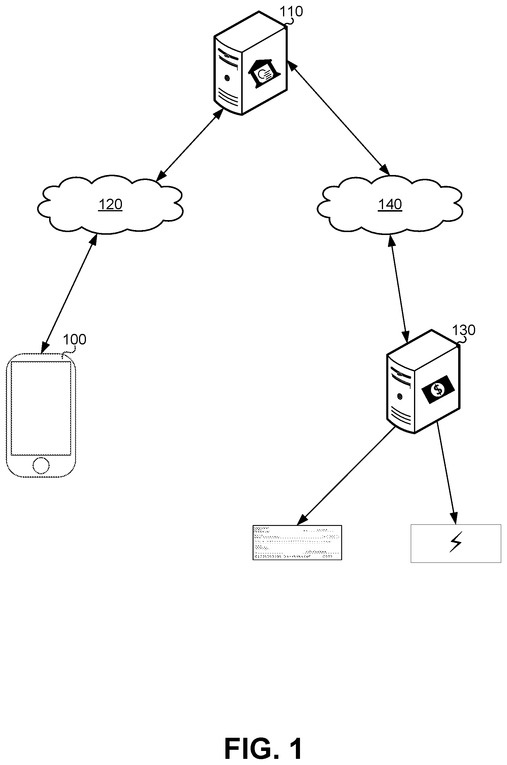
[0034] FIG. 1 is a schematic operation diagram illustrating an operating environment of an example embodiment.
[0035] As illustrated, a computing device 100 is in communication with a first server computer system 110 via a first network 120. Further, the first server computer system 110 is in communication with a second server computer system 130 via a second network 140.
[0036] The computing device 100 is a computer system. The computing device 100 may, for example, be a smartphone as shown. In another example, the computing device 100 may be a computing device of another type such as a personal computer, a laptop computer, a tablet computer, a notebook computer, a hand-held computer, a personal digital assistant, a portable navigation device, a mobile phone, a smart phone, a wearable computing device (e.g., a smart watch, a wearable activity monitor, wearable smart jewelry, and glasses and other optical devices that include optical head-mounted displays), and any other type of computing device that may be configured to store data and software instructions, and execute software instructions to perform operations consistent with disclosed embodiments.
[0037] The first server computer system 110 and the second server computer system 130 may be or may include one or more computing devices. The first server computer system 110 and the second server computer system 130 are computer server systems. A computer server system may, for example, be a mainframe computer, a minicomputer, or the like. In some implementations thereof, a computer server system may be formed of or may include one or more computing devices. A computer server system may include and/or may communicate with multiple computing devices such as, for example, database servers, compute servers, and the like. Multiple computing devices such as these may be in communication using a computer network and may communicate to act in cooperation as a computer server system. For example, such computing devices may communicate using a local-area network (LAN). In some embodiments, a computer server system may include multiple computing devices organized in a tiered arrangement. For example, a computer server system may include middle tier and back-end computing devices. In some embodiments, a computer server system may be a cluster formed of a plurality of interoperating computing devices.
[0038] The first network 120, and the second network 140 are computer networks. In some embodiments, the first network 120 and the second network 140 may be the same network. A computer network may be an internetwork such as may be formed of one or more interconnected computer networks. For example, a computer network may be or may include an Ethernet network, an asynchronous transfer mode (ATM) network, a wireless network, and/or the like. Additionally or alternatively, one or more devices may communicate with a computer network by way of a plain-old telephone service (POTS) line such as using a modem. In a particular example, one or both of the first network 120 and the second network 140 may be the Internet.
[0039] The first server computer system 110 provides functionality including allowing for the scheduling of transfers. For example, the first server computer system 110 may be associated with a financial institution and may allow for the scheduling of financial transfers such as may, for example, correspond to payments.
[0040] The second server computer system 130 cooperates with the first server computer system 110 to effect transfers. It may be that the second server computer system 130 is responsible for initiating and/or carrying out the transfers. For example, where the transfers are financial in nature such as, for example, payments, the second server computer system 130 may be associated with a financial services provider. In a particular example, the second server computer system 130 may be associated with Fiserv, Inc. of Brookfield, Wis., U.S.A.
[0041] As further described below, the computing device 100 provides user-interface allowing scheduling of transfers. In particular, the computing device 100 co-operates with the first server computer system 110 to schedule transfers and the first server computer system 110 and the second server computer system 130 co-operate to effect scheduled transfers.
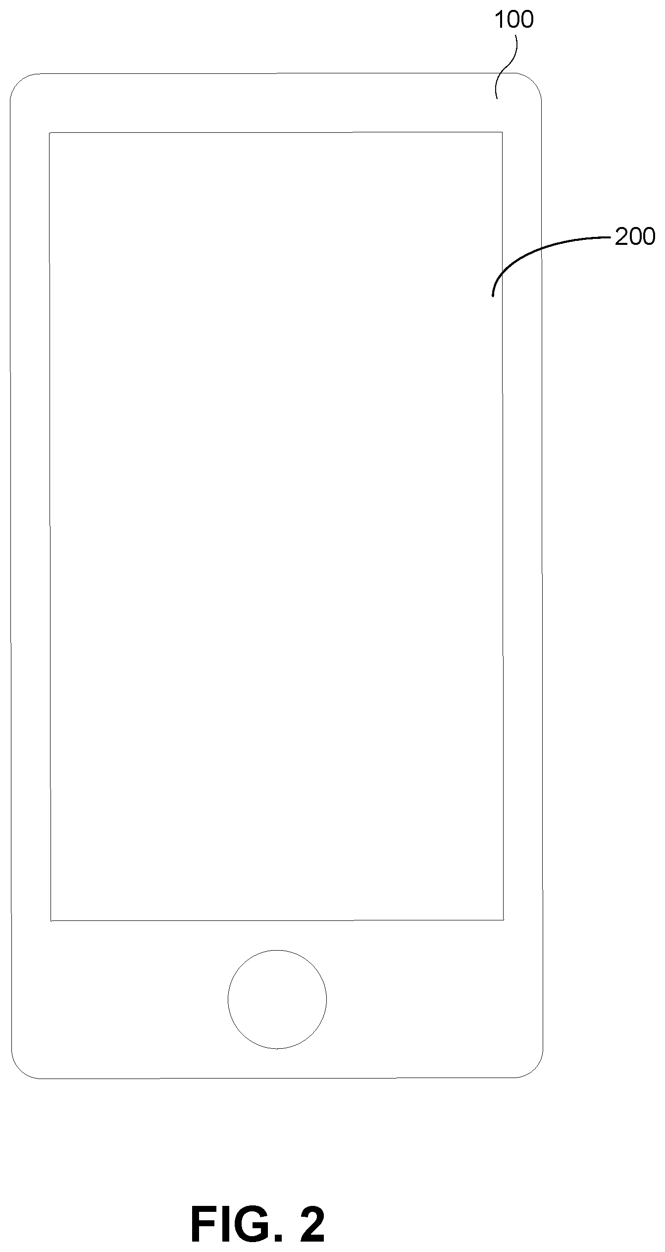
[0042] As mentioned above, the computing device 100 may be a smartphone as shown in FIG. 1. FIG. 2 is a diagram showing such an embodiment of the computing device 100.
[0043] As illustrated, the computing device 100 includes a display 200. The display 200 is a module of the illustrated embodiment of the computing device 100. The display 200 is for presenting graphics. The display 200 may be, for example, a liquid crystal display (LCD). In addition to being an output device, the display 200 may also be an input device. For example, the display 200 may allow touch input to be provided to the computing device 100. In other words, the display 200 may be a touch sensitive display module. In a particular example, the display 200 may be a capacitive touch screen.
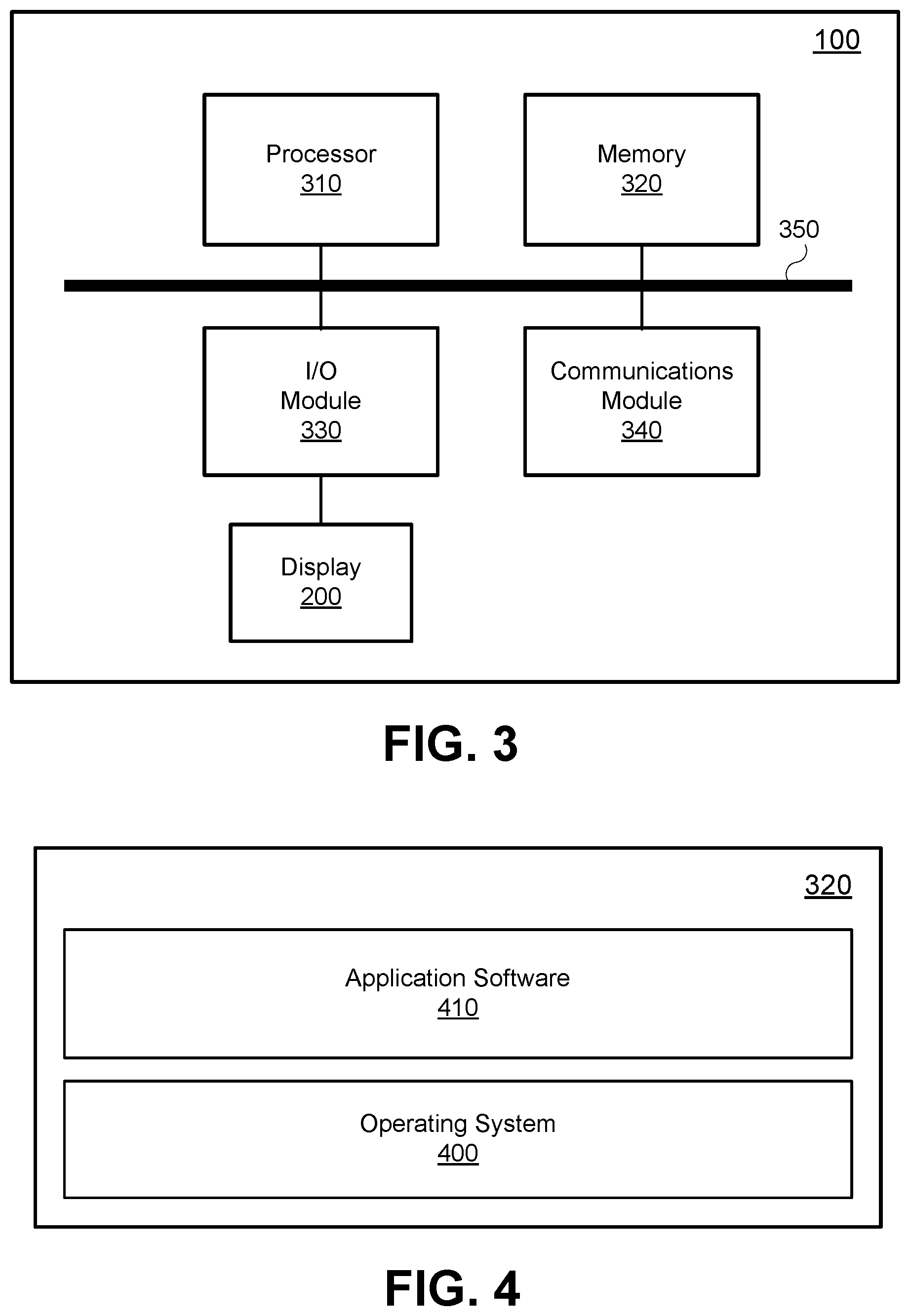
[0044] FIG. 3 is a high-level schematic diagram of the computing device 100.
[0045] The computing device 100 includes a variety of modules. For example, as illustrated, the computing device 100 may include a processor 310, a memory 320, an I/O module 330, and/or a communications module 340. As illustrated, the foregoing example modules of the computing device 100 are in communication over a bus 350.
[0046] The processor 310 is a hardware processor. The processor 310 may, for example, be one or more ARM, Intel x86, PowerPC processors or the like.
[0047] The memory 320 allows data to be stored and retrieved. The memory 320 may include, for example, random access memory, read-only memory, and persistent storage. Persistent storage may be, for example, flash memory, a solid-state drive or the like. Read-only memory and persistent storage are each computer-readable storage media and may each be considered non-transitory computer-readable storage medium. A computer-readable medium may be organized using a file system such as may be administered by an operating system governing overall operation of the computing device 100.
[0048] The I/O module 330 is both an input module and an output module. The I/O module 330 allows the computing device 100 to receive input from and/or to provide output to components of the computing device 100. For example, the I/O module 330 may, as shown, allow the computing device 100 to receive input from and/or provide output to the display 200.
[0049] The communications module 340 allows the computing device 100 to communicate with other computing devices and/or various communications networks such as, for example, the first network 120. The communications module 340 may allow the computing device 100 to send or receive communications signals. Communications signals may be sent or received according to one or more protocols or according to one or more standards. For example, the communications module 340 may allow the computing device 100 to communicate via a cellular data network, such as for example, according to one or more standards such as, for example, Global System for Mobile Communications (GSM), Code Division Multiple Access (CDMA), Evolution Data Optimized (EVDO), Long-term Evolution (LTE) or the like. Additionally or alternatively, the communications module 340 may allow the computing device 100 to communicate via Wi-Fi.TM., using Bluetooth.TM. or via some combination of one or more networks or protocols. In some embodiments, all or a portion of the communications module 340 may be integrated into a component of the computing device 100. For example, the communications module 340 may be integrated into a communications chipset.
[0050] Software comprising instructions is executed by the processor 310 from a computer-readable medium. For example, software may be loaded into random-access memory from persistent storage of the memory 320. Additionally or alternatively, instructions may be executed by the processor 310 directly from read-only memory of the memory 320.
[0051] FIG. 4 depicts a simplified organization of software components stored in the memory 320 of the computing device 100. As illustrated, these software components include an operating system 400 and an application software 410.
[0052] The operating system 400 is software. The operating system 400 allows the application software 410 to access the processor 310 (FIG. 2), the memory 320, the I/O module 330, and the communications module 340 of the computing device 100. The operating system 400 may be, for example, Google.TM. Android.TM., Apple.TM. iOS.TM., UNIX.TM., Linux.TM., Microsoft.TM. Windows.TM., Apple OSX.TM. or the like.
[0053] The application software 410 adapts the computing device 100, in combination with the operating system 400, to allow a user to schedule transfers. Where the computing device 100 is a smartphone or tablet, the application software 410 may itself be or may be a part of a smartphone or tablet application or "app". In a particular example, where the transfers are financial transfers, the application software 410 may be a mobile banking application (mobile banking app).
[0054] The operation of the computing device 100 will now be described with reference to the flowchart of FIG. 5 which illustrates a method 500 for providing a graphical user interface for scheduling transfers. In performing the method 500, operations starting from an operation 502 and continuing onward are performed by processors of one or more computing devices executing software comprising instructions. For example, some or all of the operations may be performed by the processor 310 of the computing device 100 executing software a suitable instance of the application software 410 (FIG. 4). Additionally or some or all of the operations may be performed by a processor of another computer system such as, for example, the first server computer system 110 and/or the second server computer system 130. Furthermore, it could be that some of the operations of the method 500 may be decomposed into sub-operations. Potentially, various sub-operations of a given operation may be performed by different processors/different computer systems. In a particular example, two or more of the mobile computing device 100, the first server computer system 110, and the second server computer system 130 may co-operate (e.g., via one or both of the first network 120 and the second network 140) in order to perform the method 500, with processors of the various computer systems performing various operations of the method 500 (and/or sub-operations thereof).
[0055] At the operation 502, the computing device 100 displays a calendar for a particular period. The calendar may be displayed using a display module of the computing device 100 such as, for example, the display 200.
[0056] The displayed calendar corresponds to a particular period such as, for example, a particular calendar month or portion thereof (e.g., a week or a fortnight) or some other period consisting of a number of days. As further discussed below, input may be provided to the computing device 100 selecting one of the displayed days. For example, input selecting a day may be provided by way of an input module of the computing device 100 such as, for example, by the I/O module 330. In a particular example, the I/O module may receive input provided via the display 200 where the display 200 is a touch sensitive display module. It may be that only some of the days of the displayed calendar are selectable and others of the days are not selectable. For example, the displayed calendar may include several (i.e., two or more) selectable days. The displayed calendar may also, in some cases, include one or more unselectable (i.e., not selectable) days. The computing device 100 may provide an indication of which days are selectable. For example, the displayed calendar may provide a visual indication as to selectability of particular days.
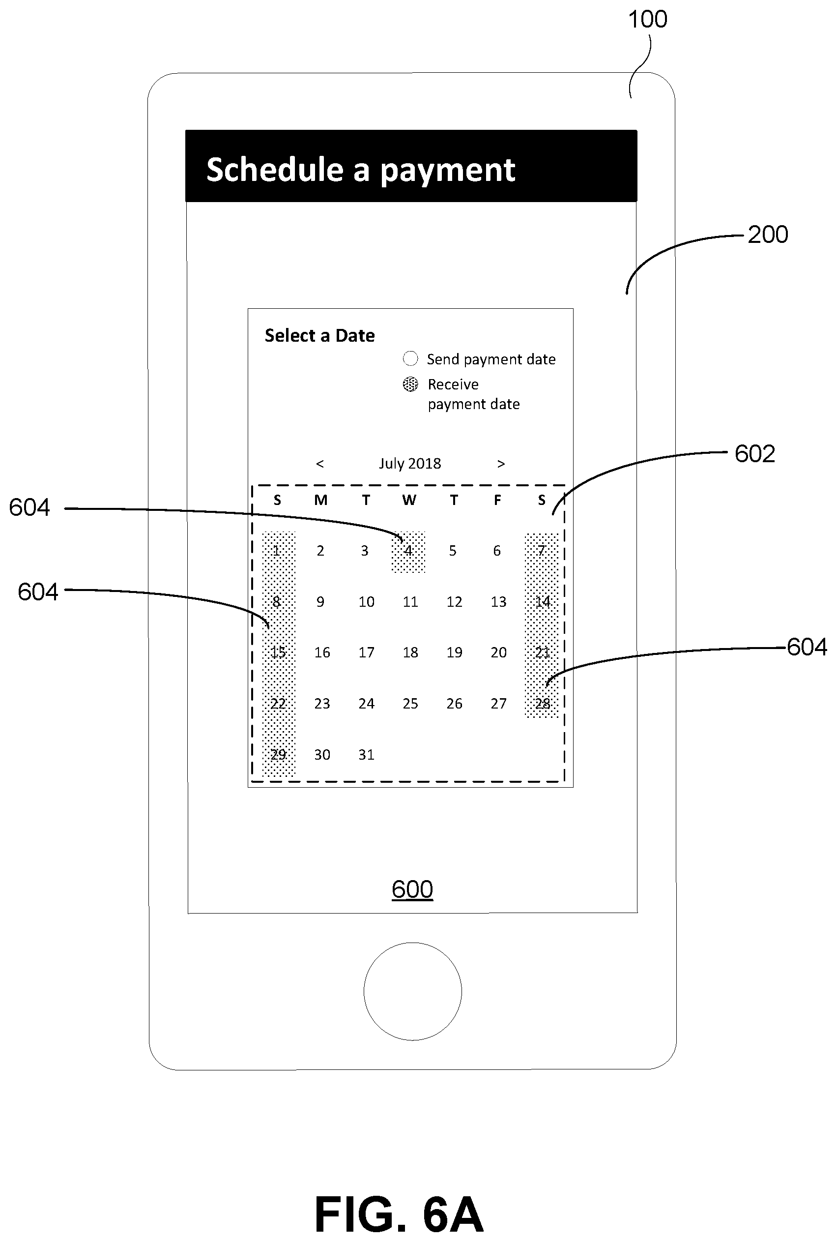
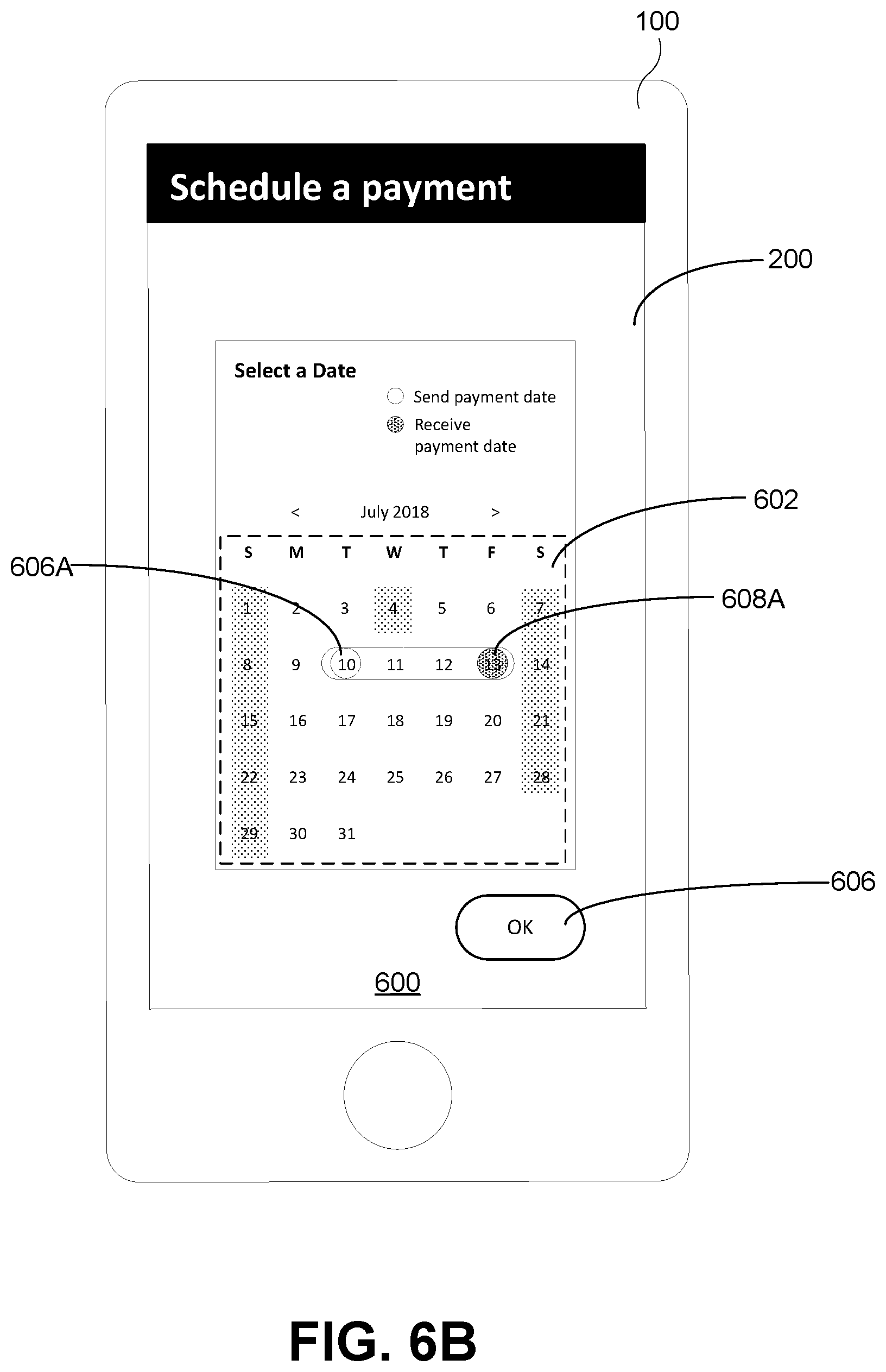
[0057] An example calendar display is shown in FIG. 6. As illustrated, the display 200 is displaying an example graphical user interface 600. The example graphical user interface 600 may be a touch sensitive interface. As mentioned above, the transfer may, in some embodiments, correspond to a payment. For example, a given transfer may correspond to payment for a bill and/or an invoice. As such, the example graphical user interface 600, as shown, characterizes its purpose as the scheduling of a payment. The example graphical user interface 600 includes a calendar 602. Notably, the example graphical user interface 600 includes shading 604 indicating non-selectable days. As shown, the non-selectable days may include non-working days such as, for example, weekends and/or holidays. For example, in the example graphical user interface 600, non-selectable days include weekends and July 4.sup.th (which is a holiday--Independence Day--in the United States). In another example, the computing device 100 may provide some non-visual indication of the selectability of a given day. For example, input attempting to select a non-selectable day may be rejected or ignored.
[0058] Notably, transfers may, in some cases, take more than one day to complete. Put another way, a transfer may be initiated on a particular date--a transfer date--and that transfer may be completed (i.e., be received) on another, later date--a transfer received date. In some embodiments, the method 500 may be reliant on a user selection of the transfer date. In other embodiments, the method 500 may be reliant on a user selection of the transfer received date. Accordingly, the nature of the selectable days may corresponding vary. Put a different way, the selectable days may be selectable as the transfer date for sending a transfer to a recipient or may be selectable as a transfer received date on which the transfer is intended to be received by the recipient.
[0059] In summary, a calendar is displayed for a particular period that includes two or more days selectable as one of a transfer date and a transfer received date. Further, the calendar may include one or more days not selectable as the one of the transfer date and the transfer received date.
[0060] Following the display of the calendar at the operation 502, an operation 504 is next.
[0061] At the operation 504, input is received selecting a first date. The input is, as mentioned above, received via an input module such as, for example, the I/O module 330. The received input may correspond to a touch input if the display 200 is touch-sensitive as discussed above. For example, a user may provide input touching a particular day in order to select it. However received, the selected date is, as mentioned above, interpreted by the computing device 100 as a selection of either a transfer date or a transfer received date depending on the particulars of the given implementation of the subject matter of the present application.
[0062] Following the selection of the first date at the operation 504, an operation 506 is next.
[0063] At the operation 506, the other of the transfer date and the transfer received date is determined based on the first date. Put another way, where the selected date corresponds to a selection of a transfer date, the transfer received date is determined and vice-versa. This other date (i.e., the date determined at the operation 506) may be determined by/using the processor 310. The other date may be determined in a variety of manners and may depend on the manner in which as transfer is to be effected. A variety of factors such as may be considered in determining the other date will now be discussed.
[0064] First, it may be that for some transfer mechanisms, whether or not transfers are available on particular dates may affect the determination of the other date. Put another way, the other date may be determined based on days on which transfers are not available. For example, a particular transfer mechanism may have the property that, once a transfer is initiated using that mechanism, the transfer can only make progress on certain days. For example, it could be that so-many working days are required to complete transfers via a particular mechanism. Notably, it may be that days on which transfers are available also correspond to the days selectable in the calendar displayed at the operation 502. For example, the selectable days may be working days on which transfer can be initiated that are also the days on which an already initiated transfer can progress.
[0065] In another example, it may be that different transfer mechanisms are used depending on one or more factors. For example, transfer mechanism may be selected based on the date the transfer is made and/or on the recipient. Selection may occur in a variety of manners. For example, it could be that particular transfer mechanisms are compatible with particular recipients. In a particular example, transfer recipients may be classed into types and then the determination of the other date may be based on the transfer mechanism to be used to effectuate the transfer to the recipient. For example, the type of a transfer recipient may correspond to one or more transfer mechanisms usable to effectuate a transfer to that recipient and, consequently, the determination of the other date may be based on the type of the recipient and/or the corresponding transfer mechanism(s).
[0066] As mentioned one or more transfer mechanisms may be available and at least one of those mechanisms may be usable to effect a transfer to a particular recipient. Considerations in determining the other date in relation to different transfer mechanisms will now be discussed.
[0067] In a first example, where the transfer corresponds to a physical transfer of an article from the sender to the recipient a courier or delivery service may be employed. For example, postal mail could be employed. Notably, such a mechanism could be employed where the transfer corresponds to a financial transfer. For example, it could be that a value instrument (e.g., a check or money order) could be printed and sent to the recipient by mail or courier. In such cases, printing may only occur at certain intervals--e.g., daily, weekly, on certain pre-defined days, and/or once a certain volume of printing requests is received for various transfers. Accordingly, such a value instrument printing interval may be considered in determining the other date. Furthermore, for a given recipient, the time to send the article via the courier or delivery service may vary--e.g., based on an expected time for the article to travel through the mails/a given courier's pipeline to the recipient from an origin (e.g., a printing facility in the case of a printed value instrument) to a recipient. Accordingly, such a delivery time (e.g., an expected postal transit time for the recipient) may, additionally or alternatively, be considered in determining the other date. Furthermore, it may be that a courier and/or the postal service only accept transfers on particular days (e.g., days they are not closed for business). Accordingly, determination of the other date may, additionally or alternatively, be based on this (e.g., postal delivery working days).
[0068] In a second example, a transfer mechanism may be employed that has certain inherent associated delays such as, for example, for processing. For example, a given electronic transfer mechanism may incur delays based on the particulars of its implementation. Such associated delays may be considered in determining the other date. In a particular example, for a particular transfer mechanism, transfers may be queued for later processing as a batch. For example, transfers could be processed on a batched basis (i.e., using batch processing techniques) at a pre-determined or scheduled interval. Put another way, a transfer by way of such a transfer mechanism may need to wait for a scheduled batch processing job. Accordingly, where batch processing of queued transfers is utilized by an employed transfer mechanism, the determination of the other date may be based on scheduled batch processing jobs.
[0069] As mentioned above, different transfer mechanisms may be employed to complete a scheduled transfer. This may, for example, be the case where the transfer corresponds to a payment. For example, the different transfer mechanisms may correspond to different payment mechanisms. Notably, the second server computer system 130 may provide access to more than one transfer mechanism.
[0070] A first example of a payment transfer mechanism that may be associated with a receiver of a payment (e.g., a payee which may, in some cases, have sent an invoice or bill to submit a payment and thus could also be referred to a biller) may be associated with payees that can only be paid using a mailed or couriered value instrument. For example, such a "paper biller" may be one for which the entity associated with the second server computer system 130 has no associated electronic billing information. For example, such a biller may not be found in a directory of known billers maintained by the second server computing system 130 or otherwise by an entity associated therewith. Notably, paying a "paper biller" may incur delays associated with transfer via mailed/couriered articles as discussed above (e.g., mailing and/or printing delays).
[0071] A second example of a payment transfer mechanism that may be associated with a payee/biller may be associated with payees found in the aforementioned directory of known billers. Notably, directory information for such "directory billers" may include information to allow payments to those billers to be processed electronically. Such a payment may be quicker than sending a printed value instrument. Notably, however, such payment may not be instantaneous or even same day. For example, payments may only be processed on business days and/or may only be processed periodically such as, for example, once a day in a batch-processing-type manner as discussed above. In a particular example, the US Automated Clearing House (ACH) Network may be employed in making such transfers.
[0072] A third example of a payment transfer mechanism associated with a payee/biller may be a "same day" mechanism provided for some payees that are not only included in the aforementioned directory of known billers but that are also eligible for "e-billing". Such "e-billers" are billers that are not only included in the directory (i.e., "e-billers" can be considered "directory billers") but also make available electronic statements as well as metadata such as statement due date, amount due, etc. E-Billers may include large well-known companies. The typical processing of payments for e-billers may have timelines similar to directory billers. However, it may be that for some e-billers, an optional "rush payment" option is provided whereby payment may be processed through an alternative fast payment channel allowing for faster payments such as, for example, "same day" payments.
[0073] It is noted that each of the above payment transfer mechanisms corresponds to a respective type of payment such as may be available when the second server computer system 130 is associated with Fiserv, Inc. as discussed above.
[0074] Notably, in some cases, the determination of the other date may be made in co-operation with the first server computer system 110. For example, it may be that some or all of the computation to determine the other date is performed by a processor of the first server computer system 110, with the first server computer system 110 and the computing device 100 communicating (e.g., over the first network 120) to co-operate in the determination of the other date. In a particular example, the computing device 100 may send one or more indications to and/or may receive one or more indications from the first server computer system 110 related to such cooperation via the first network 120 using, for example, the communications module 340.
[0075] Following determination of the other date at the operation 506, an operation 508 is next.
[0076] At the operation 508, a visual indication is displayed indicating the first date and the other date. Put another way, a visual indication is displayed indicating the selected transfer date and the determined transfer received date or the selected transfer received date and the determined transfer date, as the case may be. In either case, the indication may be provided by the computing device 100 using a display module such as, for example, the display 200. The indication may be displayed on the calendar displayed at the operation 502.
[0077] An example visual indication indicating that the first date has been selected as the one of the transfer date and the transfer received date and indicating the determined other date (i.e., the other of the transfer date and the transfer received date) is shown in FIG. 6B. As illustrated, in FIG. 6B, the example graphical user interface 600 has been updated with the addition of further visual elements. A first visual element 606A indicates the transfer date (July 10) which, in the case of the example graphical user interface 600, is the date a payment will be sent. A second visual element 608A indicates the transfer received date (July 13) which, in the case of the example graphical user interface 600, is a date the payment is expected to be received.
[0078] The example graphical user interface 600, as updated, also includes an OK button 606. The OK button 606 is an example of a user interface element such as may be employed by a user in order to confirm the selection of the pair of dates, once the user is satisfied with their selection. Notably, such a confirmation user interface element may, as illustrated, only appear once a first date selection has been made. Alternatively, it could be that the user interface element is always present but may be disabled (e.g., "greyed-out") until a first date selection is made.
[0079] Notably, a user may wish to perform "what if" scenarios in selecting a transfer date and/or a transfer received date. For example, a user may wish to compare different transfer dates to review the effect on determined transfer received dates. Notably, it may be that for certain transfer methods, transfers sent on various dates may result in the same transfer received date (e.g., in the case transfers are batch processed at particular intervals). As such, it may be that a user explores to determine the latest transfer date they can select in order to have their transfer received by an intended transfer received date. In another example, in an embodiment allowing selection of the transfer received date, a user may wish to compare different transfer received dates in order to co-ordinate when a transfer occurs. For example, in the case of a financial transfer, a user may wish to time the transfer so that it is not withdrawn before an expected deposit (e.g., not before payday).
[0080] Such "what if" functionality may be provided by allowing a user to change their selected date. The "what if" functionality is enabled by operations starting with an operation 510 which may, as illustrated, follow the operation 508. Alternatively, as depicted by a stippled arrow in FIG. 5, where the user is satisfied with the pair of dates selecting from the initial selection at the operation 504, an operation 516 may be next.
[0081] At the operation 510, input selecting a second date as the one of the transfer date and the transfer received date may be received. Notably, for a change in date, the second date may be different from the first date received at the operation 504. More broadly, it may be that, in some implementations, input selecting either of the transfer date or the transfer date may be received at the operation 510. In other words, in such implementations, the received second date may constitute a modification of either the first date received at the operation 504 or the other date determined at the operation 506. For example, in such implementations, it could be that input selecting a transfer date is received at the operation 504 but input selecting a transfer received date is received at the operation 510. The input may be saved in manners the same or similar to the receipt of input at the operation 504. For example, the input may be received by the computing device 100 by way of an input device such as, for example, the I/O module 330.
[0082] Following receipt of the second date at the operation 510, an operation 512 is next.
[0083] At the operation 512, the other date determined at the operation 506 is redetermined based on the second date received at the operation 510 (i.e., instead of based on the first date received at the operation 504). Alternatively, where the second date selected at the operation 510 corresponds to the same kind of date determined at the operation 506 (e.g., where input selecting a transfer date was received at the operation 504 but input selecting a transfer received date was received at the operation 510) then a replacement for the other date determined at the operation 506 may be determined at the operation 512. Put another way, the second date received at the operation 510 is one of an updated transfer date and an update transfer received date and, at the operation 512, the other of the transfer date and the transfer received date is determined.
[0084] Whichever date is determined at the operation 512, the determination may be made by/using the processor 310 of the computing device 100. The redetermination of the other date may be made in manners consistent with the determination of the other date at the operation 506 and similar considerations may apply in both circumstances such as, for example, those discussed above. Notably, the re-determination may be made in co-operation with the first server computer system 110 in manners similar to those discussed above in relation to possible co-operation therewith in the determination at the operation 506.
[0085] Following the redetermination of the other date at the operation 512, and operation 514 is next.
[0086] At the operation 514, a new visual indication is displayed replacing the visual indication displayed at the operation 508. This second visual indication is displayed using a display module of the computing device 100--e.g., using the display 200. The second visual indication indicates the newly selected one of the transfer date and the transferred received date (i.e., the second date received at the operation 510) and the newly determined (redetermined) other date (i.e., as determined at the operation 512). The second visual indication may be displayed as a part of the calendar displayed at the operation 502. As such, the operation 514 may include updating the display of the calendar to replace the first visual indication displayed at the operation 508 with a second visual indication indicating that the second date has been selected as one of the transfer date and transfer received date (as the case may be) and the redetermined other date (i.e., the determined other of the transfer date and the transfer received date).
[0087] FIG. 6C shows how the selection of a new transfer date (July 10) may result in and be reflected in the example graphical user interface 600 with a new visual indication replacing the visual indication added to the calendar 602 between FIGS. 6A and 6B. In particular, as illustrated, a third visual element 606B (taking the place of the first visual element 606A) is displayed showing the transfer date and a fourth visual element 608B (taking the place of second visual element 608A) is displayed showing the transfer received date.
[0088] As noted above, a user interface element (e.g., the OK button 606) may be provided for a user to confirm the date pair (i.e., the selected and the determined/re-determined date) if satisfied. Following the operation 514 (or the operation 508 if the user is satisfied with the initial date selection as mentioned above), input confirming the currently selected dates may be received at the operation 516. Alternatively, as depicted by a stippled arrow in FIG. 5, the user may, following the display of the visual indication at the operation 514, continue to modify the dates until satisfied. In such a case, control flow may return from the operation 514 to the operation 510 so that a new date selection may be received and a resulting other date determined and then both revised dates may be displayed.
[0089] As mentioned above, at the operation 516, input confirming the dates (e.g., the user's satisfaction therewith), namely the selected date and the determined other date (i.e., the transfer date and the transferred received date or vice-versa, as the case may be) is received by the computing device 100. The input may be received in manners the same or similar to the receipt of input at the operation 504. For example, the input may be received by the computing device 100 by way of an input device such as, for example, the I/O module 330. The received input may correspond to an interaction with a confirmation user interface element such as, for example, the OK button 606. For example, the received input may correspond to a click or touch of the OK button 606. Whatever the form of the received input and however the input is received, by providing such input the user may signal that they are satisfied with the transfer date and the transfer received date. Additionally, the input may signal that a choice to go ahead with scheduling the transfer.
[0090] Following the operation 516, at an operation 518, the transfer may be scheduled by the computing device 100 (potentially in co-operation with one or more other computer systems). Put another way, at the operation 516, the computing device may initiate scheduling of the transfer. For example, the computing device may communicate with the first server computer system 110 such as, for example, by way of one or more indications sent to by the computing device 100 to the first server computer system 110, in order to request the scheduling of the transfer on the transfer date. In a particular example, an indication may be sent by the computing device 100 via the first network 120 such as, for example, using the communications module 340. The first server computer system 110 may then, responsive to an indication received from the computing device 100, send a communication to the second server computer system 130 (e.g., via the second network 140) to effect the transfer. For example, such an indication may be sent when it is time to initiate a scheduled transfer. In another example, such an indication may be sent in advance of the scheduled transfer. For example, it may be that the first server computer system 110 communicates with the second server computer system 130 (e.g., responsive to an indication from the computing device 100) to schedule the transfer and the second server computer system 130 is then responsible for effecting the transfer as scheduled.
[0091] As mentioned above, in some cases, it is possible that more than one transfer mechanism may be available to effect a given transfer. For example, it may be that the available transfer mechanisms include a first transfer mechanism and a second transfer mechanism. The transfer mechanisms may vary in terms of speed. For example, the first transfer mechanism may be slower than the second transfer mechanism. It may be that, in the method 500, the other date is determined at the operation 506 (and re-determined at the operation 512) based on the first transfer mechanism. In such a case, the computing device 100 may (e.g., concurrent with or subsequent to the performing of one or both of the operation 506 and the operation 512) further determine another transfer received date on which a transfer made on a given date (which could be the same or different as the transfer date as determined or received) is projected to be received by the recipient. A further visual indication may then be displayed showing when a transfer effectuated using the second transfer mechanism would be received (i.e., showing the determined transfer received date for the second transfer mechanism). For example, it could be that the given date is a transfer date as previously received at the operation 504 and the further visual indication serves to allow a user to compare the results of using different transfer mechanisms to perform a transfer scheduled for that date. Notably, where a choice of transfer mechanisms is provided, there may be associated considerations (potentially including considerations other than transfer time) with each. For example, where the first and second transfer mechanism are payment mechanisms, there may be different fees associated therewith. In another example, it could be that the second transfer mechanism is or includes a "same day" mechanism and the given date is the transfer date or even the current date. In such a case, the determined transfer received date may be either the received transfer date or the current date (as the case may be) or a next day on which "same day" transfers are available (e.g., if "same day" transfers are only available on selected business days such as, for example, if they can only be made on working/business days).
[0092] FIG. 7 which shows a second example graphical user interface 700 including a further visual indication showing when a transfer effectuated using an alternative transfer mechanism would be received. As illustrated, July 12 has been selected as transfer date from amongst selectable dates of a calendar 702. A first visual element 706 indicates this selection. A second visual element 708 shows the corresponding transfer received date of July 13. A third visual element 710 shows that an alternative "rush" payment mechanism can also be employed for the payee, in this case allowing for the payment to be received "same day" (on the same day as) the date the payment is to be sent. The second example graphical user interface 700 also includes an OK button 712. The OK button 712 may provide similar functionality and/or may be used for similar purposes at the OK button 606 (FIG. 6).
[0093] As discussed above, the received one of the transfer date or the transfer received date is determined entirely based on input. In some embodiments, a default value may be provided. For example, it could be that a current date is used as an initial/default transfer date. In another example, where a due date for a transfer is known (e.g., a due date for a bill in the case of a transfer corresponding to payment for that bill), an initial/default transfer date may be provided allowing for an (as late as possible) on-time payment. Notably, an indication of a due date for a transfer may be received such as, for example, from the second server computer system 130 (e.g., via the first network 120). For example, an indication of the due date for a transfer may be received by the computing device 100 using the communications module 340). Notably, such a transfer due date may, in the case of a transfer corresponding to a payment, be received by way of the second server computer system 130 such as, for example, where the received data corresponds to data about an "e-biller" as discussed above. However determined, such a default transfer date may be reflected in the graphical user interface (e.g., as initially displayed) as presented by the computing device 100. For example, the computing device 100 may present the due date for the transfer being configured.
[0094] Example embodiments of the present application are not limited to any particular operating system, system architecture, computing device architecture, server architecture, or computer programming language.
[0095] It will be understood that the applications, modules, routines, processes, threads, or other software components implementing the described method/process may be realized using standard computer programming techniques and languages. The present application is not limited to particular processors, computer languages, computer programming conventions, data structures, or other such implementation details. Those skilled in the art will recognize that the described processes may be implemented as a part of computer-executable code stored in volatile or non-volatile memory, as part of an application-specific integrated chip (ASIC), etc.
[0096] As noted, certain adaptations and modifications of the described embodiments can be made. Therefore, the above discussed embodiments are considered to be illustrative and not restrictive.
* * * * *
D00000
D00001
D00002
D00003
D00004
D00005
D00006
D00007
D00008
XML
uspto.report is an independent third-party trademark research tool that is not affiliated, endorsed, or sponsored by the United States Patent and Trademark Office (USPTO) or any other governmental organization. The information provided by uspto.report is based on publicly available data at the time of writing and is intended for informational purposes only.
While we strive to provide accurate and up-to-date information, we do not guarantee the accuracy, completeness, reliability, or suitability of the information displayed on this site. The use of this site is at your own risk. Any reliance you place on such information is therefore strictly at your own risk.
All official trademark data, including owner information, should be verified by visiting the official USPTO website at www.uspto.gov. This site is not intended to replace professional legal advice and should not be used as a substitute for consulting with a legal professional who is knowledgeable about trademark law.