Alignment Sleeve Assembly And Fiber Optic Adapter
Tong; Zhaoyang ; et al.
U.S. patent application number 16/419372 was filed with the patent office on 2020-05-07 for alignment sleeve assembly and fiber optic adapter. This patent application is currently assigned to CommScope Telecommunications (Shanghai) Co., Ltd.. The applicant listed for this patent is CommScope Telecommunications (Shanghai) Co., Ltd.. Invention is credited to Xingjun Cheng, Lei Liu, Zhaoyang Tong.
| Application Number | 20200142137 16/419372 |
| Document ID | / |
| Family ID | 57318899 |
| Filed Date | 2020-05-07 |

View All Diagrams
| United States Patent Application | 20200142137 |
| Kind Code | A1 |
| Tong; Zhaoyang ; et al. | May 7, 2020 |
ALIGNMENT SLEEVE ASSEMBLY AND FIBER OPTIC ADAPTER
Abstract
A fiber optic adapter, including: a mating retainer; an alignment sleeve received in the mating retainer, a ferrule of a fiber optic connector being adapted to be inserted into the alignment sleeve through an insertion port of the fiber optic adapter; and an adjustment element configured to adjust a circumferential angle of the alignment sleeve relative to the mating retainer to a predetermined circumferential angle and hold the alignment sleeve at the predetermined circumferential angle relative to the mating retainer. The adjustment element may adjust the circumferential angle of the alignment sleeve with respect to the mating retainer to the predetermined circumferential angle, for example, at which the fiber insertion loss of the coupled connectors is minimal, and hold the alignment sleeve at the predetermined circumferential angle. In this way, it may improve the alignment accuracy of the coupled connectors.
| Inventors: | Tong; Zhaoyang; (Shanghai, CN) ; Cheng; Xingjun; (Jiangsu Province, CN) ; Liu; Lei; (Hangzhou City, CN) | ||||||||||
| Applicant: |
|
||||||||||
|---|---|---|---|---|---|---|---|---|---|---|---|
| Assignee: | CommScope Telecommunications
(Shanghai) Co., Ltd. Shanghai CN |
||||||||||
| Family ID: | 57318899 | ||||||||||
| Appl. No.: | 16/419372 | ||||||||||
| Filed: | May 22, 2019 |
Related U.S. Patent Documents
| Application Number | Filing Date | Patent Number | ||
|---|---|---|---|---|
| 15574389 | Nov 15, 2017 | 10302874 | ||
| PCT/CN2016/082021 | May 13, 2016 | |||
| 16419372 | ||||
| Current U.S. Class: | 1/1 |
| Current CPC Class: | G02B 6/3871 20130101; G02B 6/3874 20130101; G02B 6/38 20130101; G02B 6/3825 20130101 |
| International Class: | G02B 6/38 20060101 G02B006/38 |
Foreign Application Data
| Date | Code | Application Number |
|---|---|---|
| May 15, 2015 | CN | 201510247621.4 |
| May 15, 2015 | CN | 201520319609.5 |
Claims
1. A fiber optic adapter, comprising: a mating retainer; an alignment sleeve received in the mating retainer, a ferrule of a fiber optic connector being adapted to be inserted into the alignment sleeve through an insertion port of the fiber optic adapter; and an adjustment element configured to adjust a circumferential angle of the alignment sleeve relative to the mating retainer to a predetermined circumferential angle and hold the alignment sleeve at the predetermined circumferential angle relative to the mating retainer.
2. The fiber optic adapter according to claim 1, wherein when the alignment sleeve is held at the predetermined circumferential angle relative to the mating retainer, an alignment error between fiber cores of fibers, inserted into the alignment sleeve of the fiber optic adapter, of a pair of fiber optic connectors is minimal.
3. The fiber optic adapter according to claim 1, wherein when the alignment sleeve is held at the predetermined circumferential angle relative to the mating retainer, a longitudinal slot in the alignment sleeve is positioned at a predetermined orientation.
4. The fiber optic adapter according to claim 2, wherein the adjustment element is adapted to be sleeved on the alignment sleeve, and a radial protrusion is formed on an inner wall of the adjustment element and adapted to be inserted into the longitudinal slot of the alignment sleeve, so that the alignment sleeve is rotatable with the alignment element, and the circumferential angle of the alignment sleeve relative to the mating retainer is adjustable by rotating the adjustment element.
5. The fiber optic adapter according to claim 4, wherein when the radial protrusion of the adjustment element is inserted into the longitudinal slot of the alignment sleeve, the alignment sleeve is limited to be rotated in a circumferential direction relative to the adjustment element.
6. The fiber optic adapter according to claim 4, wherein when the radial protrusion of the adjustment element is inserted into the longitudinal slot of the alignment sleeve, the alignment sleeve is limited to be rotated in a range of .+-.30 degrees in a circumferential direction relative to the adjustment element.
7. The fiber optic adapter according to claim 4, wherein when the radial protrusion of the adjustment element is inserted into the longitudinal slot of the alignment sleeve, the alignment sleeve is limited to be rotated in a range of .+-.20 degrees in a circumferential direction relative to the adjustment element.
8. The fiber optic adapter according to claim 4, wherein when the radial protrusion of the adjustment element is inserted into the longitudinal slot of the alignment sleeve, the alignment sleeve is limited to be rotated in a range of .+-.10 degrees in a circumferential direction relative to the adjustment element.
9. The fiber optic adapter according to claim 4, wherein the adjustment element is formed as a polygonal prism with a polygon cross section; wherein a positioning slot, corresponding to an outer profile of the adjustment element, is formed in the mating retainer; and wherein the adjustment element is adapted to be fixed in the positioning slot of the mating retainer, so as to hold the alignment sleeve at the predetermined circumferential angle relative to the mating retainer.
10. The fiber optic adapter according to claim 4, wherein the adjustment element is formed with multiple spline keys, and the mating retainer is formed with multiple spline slots; and wherein the multiple spline keys of the adjustment element are adapted to be fitted in the multiple spline slots of the mating retainer, so as to hold the alignment sleeve at the predetermined circumferential angle relative to the mating retainer.
11. The fiber optic adapter according to claim 9, wherein a first circumferential angle mark is provided on an outer surface of the adjustment element, and a second circumferential angle mark is provided on the mating retainer; and when the alignment sleeve is adjusted to the predetermined circumferential angle by the adjustment element, the first circumferential angle mark of the adjustment element is aligned with the second circumferential angle mark of the mating retainer.
12. The fiber optic adapter according to claim 11, further comprises a housing in which the mating retainer are mounted; and wherein an alignment slot, configured to mate with a sliding block on the fiber optic connector, is formed in the housing, so as to ensure the fiber optic connector is inserted into the fiber optic adapter in a correct orientation relative to the fiber optic adapter.
13. The fiber optic adapter according to claim 12, when the alignment sleeve is adjusted to the predetermined circumferential angle by the adjustment element, the first circumferential angle mark and the second circumferential angle mark are aligned with the alignment slot of the housing.
14. The fiber optic adapter according to claim 13, wherein the second circumferential angle mark of the mating retainer comprises a notch formed in the mating retainer; wherein an foolproof assembly protrusion, configured to mate with the notch of the mating retainer, is formed on an inner wall of the housing; and wherein the mating retainer is assembled into the housing only when the foolproof assembly protrusion of the housing is aligned with the notch of the mating retainer.
15. The fiber optic adapter according to claim 12, further comprises a fixation element adapted to be mounted on the housing and hold a tube-like body of the mating retainer, so as to prevent the mating retainer from being pulled out of the housing.
16. The fiber optic adapter according to claim 12, further comprises an elastic snapper mounted on the housing and configured to lock the fiber optic adapter in a fixation installation position.
17. The fiber optic adapter according to claim 9, wherein the mating retainer comprises a first mating retainer and a second mating retainer being assembled together.
18. The fiber optic adapter according to claim 17, wherein the positioning slot comprises a first positioning slot and a second positioning slot, aligned to each other, formed in mating ends of the first mating retainer and the second mating retainer, respectively.
19. The fiber optic adapter according to claim 18, wherein the second circumferential angle mark comprises a first notch and a second notch, aligned to each other, formed in the mating ends of the first mating retainer and the second mating retainer, respectively.
20. The fiber optic adapter according to claim 1, wherein the fiber optic adapter is adapted to interconnect one or more pairs of fiber optic connectors at the same time; and wherein one or more alignment sleeves, configured to align ferrules of one or more pairs of fiber optic connectors, are received in the retainer.
21. An alignment sleeve assembly, comprising: an alignment sleeve adapted to be received in a mating retainer of a fiber optic adapter; and an adjustment element configured to adjust a circumferential angle of the alignment sleeve relative to the mating retainer to a predetermined circumferential angle and hold the alignment sleeve at the predetermined circumferential angle relative to the mating retainer.
22. The alignment sleeve assembly according to claim 21, wherein the adjustment element is adapted to be sleeved on the alignment sleeve, and a radial protrusion is formed on an inner wall of the adjustment element and adapted to be inserted into the longitudinal slot of the alignment sleeve, so that the alignment sleeve is rotatable with the alignment element, and the circumferential angle of the alignment sleeve relative to the mating retainer is adjustable by rotating the adjustment element.
23. The alignment sleeve assembly according to claim 22, when the radial protrusion of the adjustment element is inserted into the longitudinal slot of the alignment sleeve, the alignment sleeve is limited to be rotated in a circumferential direction relative to the adjustment element.
24. The alignment sleeve assembly according to claim 22, when the radial protrusion of the adjustment element is inserted into the longitudinal slot of the alignment sleeve, the alignment sleeve is limited to be rotated in a range of .+-.30 degrees in a circumferential direction relative to the adjustment element.
25. The alignment sleeve assembly according to claim 22, when the radial protrusion of the adjustment element is inserted into the longitudinal slot of the alignment sleeve, the alignment sleeve is limited to be rotated in a range of .+-.20 degrees in a circumferential direction relative to the adjustment element.
26. The alignment sleeve assembly according to claim 22, when the radial protrusion of the adjustment element is inserted into the longitudinal slot of the alignment sleeve, the alignment sleeve is limited to be rotated in a range of .+-.10 degrees in a circumferential direction relative to the adjustment element.
27. The alignment sleeve assembly according to claim 23, wherein the adjustment element is formed as a polygonal prism with a polygon cross section;
28. The alignment sleeve assembly according to claim 27, wherein a first circumferential angle mark, configured to identify the predetermined circumferential angle of the alignment sleeve relative to the mating retainer, is provided on an outer surface of the adjustment element.
Description
[0001] This application is a Continuation of U.S. patent application Ser. No. 15/574,389, filed on 15 Nov. 2017, which is a National Stage Application of PCT/CN2016/082021, filed on 13 May 2016, which claims benefit of Serial No. 201510247621.4, filed on 15 May 2015 in China and Serial No. 201520319609.5, filed on 15 May 2015 in China and which applications are incorporated herein by reference. To the extent appropriate, a claim of priority is made to each of the above disclosed applications.
BACKGROUND OF THE INVENTION
Field of the Invention
[0002] The present invention relates to an alignment sleeve assembly and a fiber optic adapter comprising the alignment sleeve assembly.
Description of the Related Art
[0003] In the prior art, a fiber optic adapter (for convenience of description, herein take a single-fiber SC adapter as an example) generally comprises an alignment sleeve, a mating retainer for receiving the alignment sleeve therein and locking a pair of coupled fiber optic connectors, a housing, a buckle type fixing clamp spring and a warranty buckle (optional).
[0004] In the prior art, there is machining error in the alignment sleeve, for example, inner wall roundness of the alignment sleeve is not enough, and wall thickness of the alignment sleeve is not uniform. As a result, when ferrules of a pair of fiber optic connectors are inserted into the alignment sleeve of the fiber optic adapter from opposite ends of the alignment sleeve and coupled with each other, in addition to an alignment error, which will lead to a connection loss, between fiber cores of the coupled connectors, the alignment sleeve will also cause a certain alignment error, it will further increase the connection loss or increase the connection loss uncertainty. For an individual alignment sleeve, only when the alignment sleeve is located at a particular circumferential angle, the connection loss caused by it is minimal.
[0005] In the prior art, for batch manufacturing, the particular circumferential angle of each individual alignment sleeve corresponding to the minimum connection loss is apt to be different. Furthermore, the alignment sleeve is not positioned and fixed in the circumferential direction, and the alignment sleeve may rotate randomly. Therefore, minimizing the connection loss by positioned the alignment sleeve at the particular circumferential angle is not recognized and well utilized yet by the existing design.
[0006] As for the fiber optic adapter in the prior art, the alignment sleeve may freely rotate in the mating retainer along the circumferential direction and have a certain degree of freedom in three directions perpendicular to each other. Since the alignment sleeve has a certain tolerance, the connection loss of the coupled connectors has certain polarity. That is, only when the alignment sleeve is positioned at the particular circumferential angle, the coupled connectors may achieve the minimum insertion loss. However, in the prior art, the alignment sleeve may be rotated randomly. Thereby, the insertion loss of the entire optical fiber interconnection system is not always kept in a state of minimum loss. In other words, the random nature of the circumferential angle of the alignment sleeve affects the total insertion loss of the fiber interconnection system. Such situation does not meet strict requirements on ultra low insertion loss of optical fiber interconnection system in future and requirements on the repeatability of the ultra low insertion loss after the fiber optic connectors are decoupled.
SUMMARY OF THE INVENTION
[0007] The present invention has been made to overcome or alleviate at least one aspect of the above mentioned disadvantages.
[0008] According to an object of the present invention, there is provided an alignment sleeve assembly and a fiber optic adapter comprising the alignment sleeve assembly, in which an alignment sleeve may be adjusted to and fixed at a predetermined circumferential angle, at which the fiber optic insertion loss is minimal, with respect to a mating retainer. In this way, it improves the alignment accuracy of a pair of coupled fiber optic connectors.
[0009] According to an aspect of the present invention, there is provided a fiber optic adapter, comprising: a mating retainer; an alignment sleeve received in the mating retainer, wherein a ferrule of a fiber optic connector is adapted to be inserted into the alignment sleeve through an insertion port of the fiber optic adapter; and an adjustment element configured to adjust a circumferential angle of the alignment sleeve relative to the mating retainer to a predetermined circumferential angle and hold the alignment sleeve at the predetermined circumferential angle relative to the mating retainer.
[0010] According to an exemplary embodiment of the present invention, when the alignment sleeve is held at the predetermined circumferential angle relative to the mating retainer, an alignment error between fiber cores of fibers, inserted into the alignment sleeve of the fiber optic adapter, of a pair of fiber optic connectors is minimal.
[0011] According to another exemplary embodiment of the present invention, when the alignment sleeve is held at the predetermined circumferential angle relative to the mating retainer, a longitudinal slot in the alignment sleeve is positioned at a predetermined orientation.
[0012] According to another exemplary embodiment of the present invention, the adjustment element is adapted to be sleeved on the alignment sleeve, and a radial protrusion is formed on an inner wall of the adjustment element and adapted to be inserted into the longitudinal slot of the alignment sleeve, so that the alignment sleeve is capable of being rotated with the alignment element, and the circumferential angle of the alignment sleeve relative to the mating retainer is capable of being adjusted by rotating the adjustment element.
[0013] According to another exemplary embodiment of the present invention, when the radial protrusion of the adjustment element is inserted into the longitudinal slot of the alignment sleeve, the alignment sleeve is unable to be rotated in a circumferential direction relative to the adjustment element.
[0014] According to another exemplary embodiment of the present invention, when the radial protrusion of the adjustment element is inserted into the longitudinal slot of the alignment sleeve, the alignment sleeve is only able to be rotated in a range of .+-.30 degrees in a circumferential direction relative to the adjustment element.
[0015] According to another exemplary embodiment of the present invention, when the radial protrusion of the adjustment element is inserted into the longitudinal slot of the alignment sleeve, the alignment sleeve is only able to be rotated in a range of .+-.20 degrees in a circumferential direction relative to the adjustment element.
[0016] According to another exemplary embodiment of the present invention, when the radial protrusion of the adjustment element is inserted into the longitudinal slot of the alignment sleeve, the alignment sleeve is only able to be rotated in a range of .+-.10 degrees in a circumferential direction relative to the adjustment element.
[0017] According to another exemplary embodiment of the present invention, the adjustment element is formed as a polygonal prism with a polygon cross section; a positioning slot, corresponding to an outer profile of the adjustment element, is formed in the mating retainer; the adjustment element is adapted to be fixed in the positioning slot of the mating retainer, so as to hold the alignment sleeve at the predetermined circumferential angle relative to the mating retainer.
[0018] According to another exemplary embodiment of the present invention, the adjustment element is formed with multiple spline keys, and the mating retainer is formed with multiple spline slots; the multiple spline keys of the adjustment element are adapted to be fitted in the multiple spline slots of the mating retainer, so as to hold the alignment sleeve at the predetermined circumferential angle relative to the mating retainer.
[0019] According to another exemplary embodiment of the present invention, a first circumferential angle mark is provided on an outer surface of the adjustment element, and a second circumferential angle mark is provided on the mating retainer; when the alignment sleeve is adjusted to the predetermined circumferential angle by the adjustment element, the first circumferential angle mark of the adjustment element is aligned with the second circumferential angle mark of the mating retainer.
[0020] According to another exemplary embodiment of the present invention, the fiber optic adapter further comprises a housing in which the mating retainer are mounted; an alignment slot, configured to mate with a sliding block on the fiber optic connector, is formed in the housing, so as to ensure the fiber optic connector is inserted into the fiber optic adapter in a correct orientation relative to the fiber optic adapter.
[0021] According to another exemplary embodiment of the present invention, when the alignment sleeve is adjusted to the predetermined circumferential angle by the adjustment element, the first circumferential angle mark and the second circumferential angle mark are aligned with the alignment slot of the housing.
[0022] According to another exemplary embodiment of the present invention, the second circumferential angle mark of the mating retainer comprises a notch formed in the mating retainer; an foolproof assembly protrusion, configured to mate with the notch of the mating retainer, is formed on an inner wall of the housing; and the retainer is able to be assembled into the housing only when the foolproof assembly protrusion of the housing is aligned with the notch of the mating retainer.
[0023] According to another exemplary embodiment of the present invention, the fiber optic adapter further comprises a fixation element adapted to be mounted on the housing and hold a tube-like body of the mating retainer, so as to prevent the mating retainer from being pulled out of the housing.
[0024] According to another exemplary embodiment of the present invention, the fiber optic adapter further comprises an elastic snapper mounted on the housing and configured to lock the fiber optic adapter in a fixation installation position.
[0025] According to another exemplary embodiment of the present invention, the mating retainer comprises a first mating retainer and a second mating retainer capable of being assembled together.
[0026] According to another exemplary embodiment of the present invention, the positioning slot comprises a first positioning slot and a second positioning slot, aligned to each other, formed in mating ends of the first mating retainer and the second mating retainer, respectively.
[0027] According to another exemplary embodiment of the present invention, the second circumferential angle mark comprises a first notch and a second notch, aligned to each other, formed in the mating ends of the first mating retainer and the second mating retainer, respectively.
[0028] According to another exemplary embodiment of the present invention, the fiber optic adapter is adapted to interconnect one or more pairs of fiber optic connectors at the same time; one or more alignment sleeves, configured to align ferrules of one or more pairs of fiber optic connectors, are received in the retainer.
[0029] According to another aspect of the present invention, there is provided an alignment sleeve assembly, comprising: an alignment sleeve adapted to be received in a mating retainer of a fiber optic adapter; and an adjustment element configured to adjust a circumferential angle of the alignment sleeve relative to the mating retainer to a predetermined circumferential angle and hold the alignment sleeve at the predetermined circumferential angle relative to the mating retainer.
[0030] According to an exemplary embodiment of the present invention, the adjustment element is adapted to be sleeved on the alignment sleeve, and a radial protrusion is formed on an inner wall of the adjustment element and adapted to be inserted into the longitudinal slot of the alignment sleeve, so that the alignment sleeve is capable of being rotated with the alignment element, and the circumferential angle of the alignment sleeve relative to the mating retainer is capable of being adjusted by rotating the adjustment element.
[0031] According to another exemplary embodiment of the present invention, when the radial protrusion of the adjustment element is inserted into the longitudinal slot of the alignment sleeve, the alignment sleeve is unable to be rotated in a circumferential direction relative to the adjustment element.
[0032] According to another exemplary embodiment of the present invention, when the radial protrusion of the adjustment element is inserted into the longitudinal slot of the alignment sleeve, the alignment sleeve is only able to be rotated in a range of .+-.30 degrees in a circumferential direction relative to the adjustment element.
[0033] According to another exemplary embodiment of the present invention, when the radial protrusion of the adjustment element is inserted into the longitudinal slot of the alignment sleeve, the alignment sleeve is only able to be rotated in a range of .+-.20 degrees in a circumferential direction relative to the adjustment element.
[0034] According to another exemplary embodiment of the present invention, when the radial protrusion of the adjustment element is inserted into the longitudinal slot of the alignment sleeve, the alignment sleeve is only able to be rotated in a range of .+-.10 degrees in a circumferential direction relative to the adjustment element.
[0035] According to another exemplary embodiment of the present invention, the adjustment element is formed as a polygonal prism with a polygon cross section;
[0036] According to another exemplary embodiment of the present invention, a first circumferential angle mark, configured to identify the predetermined circumferential angle of the alignment sleeve relative to the mating retainer, is provided on an outer surface of the adjustment element.
[0037] In the above various exemplary embodiments of the present invention, the adjustment element is constructed to adjust the circumferential angle of the alignment sleeve with respect to the mating retainer to the predetermined circumferential angle, for example, at which the fiber insertion loss of the coupled connectors is minimal, and hold the alignment sleeve at the predetermined circumferential angle. In this way, it may improve the alignment accuracy of the coupled connectors.
BRIEF DESCRIPTION OF THE DRAWINGS
[0038] The above and other features of the present invention will become more apparent by describing in detail exemplary embodiments thereof with reference to the accompanying drawings, in which:
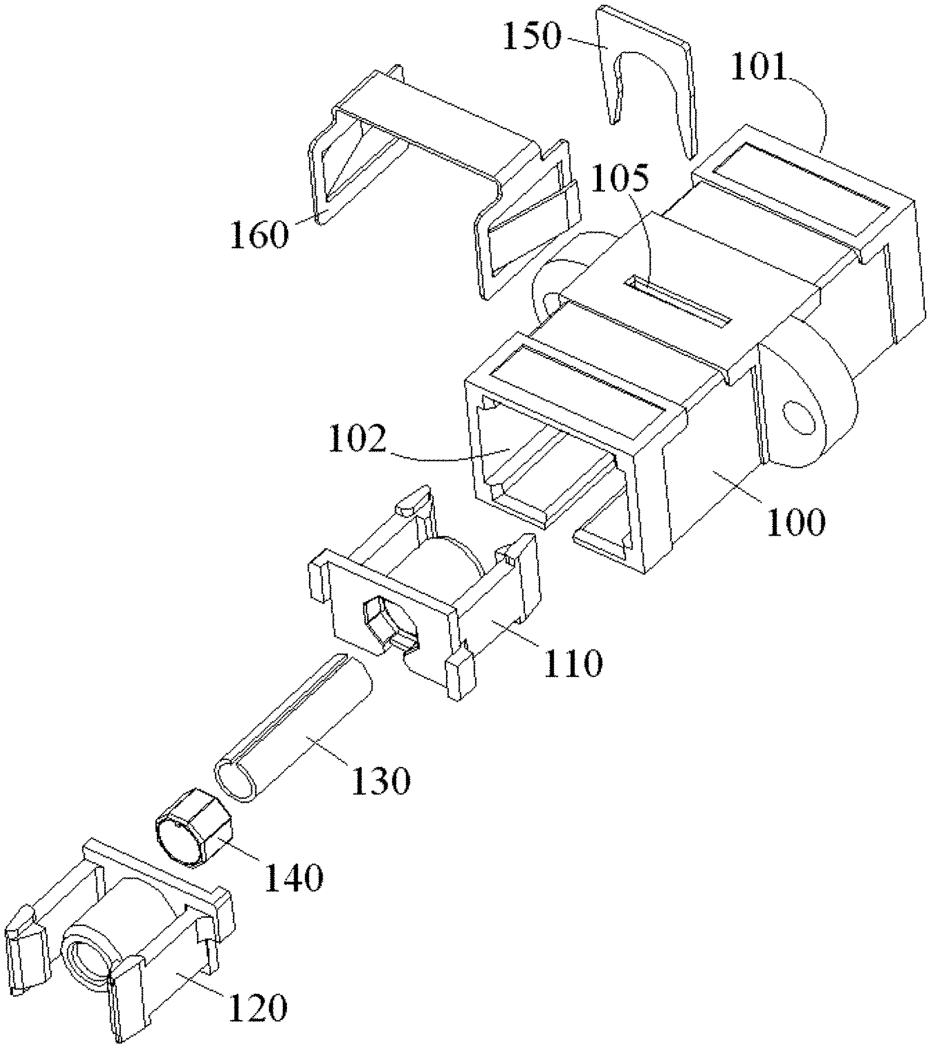
[0039] FIG. 1 is an illustrative exploded view of a fiber optic adapter according to a first exemplary embodiment of the present invention;
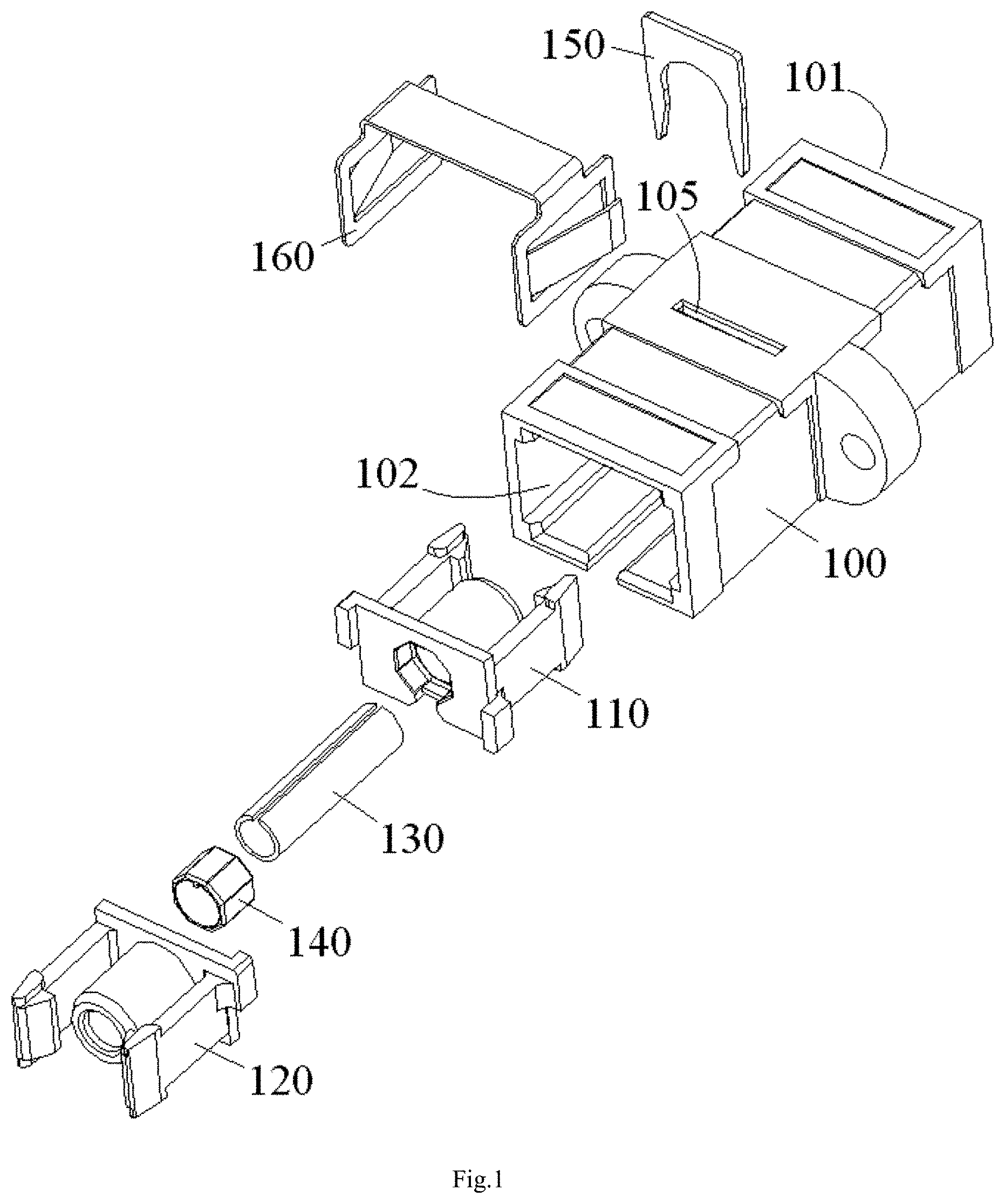
[0040] FIG. 2 is an illustrative perspective view of an adjustment element of the fiber optic adapter of FIG. 1;
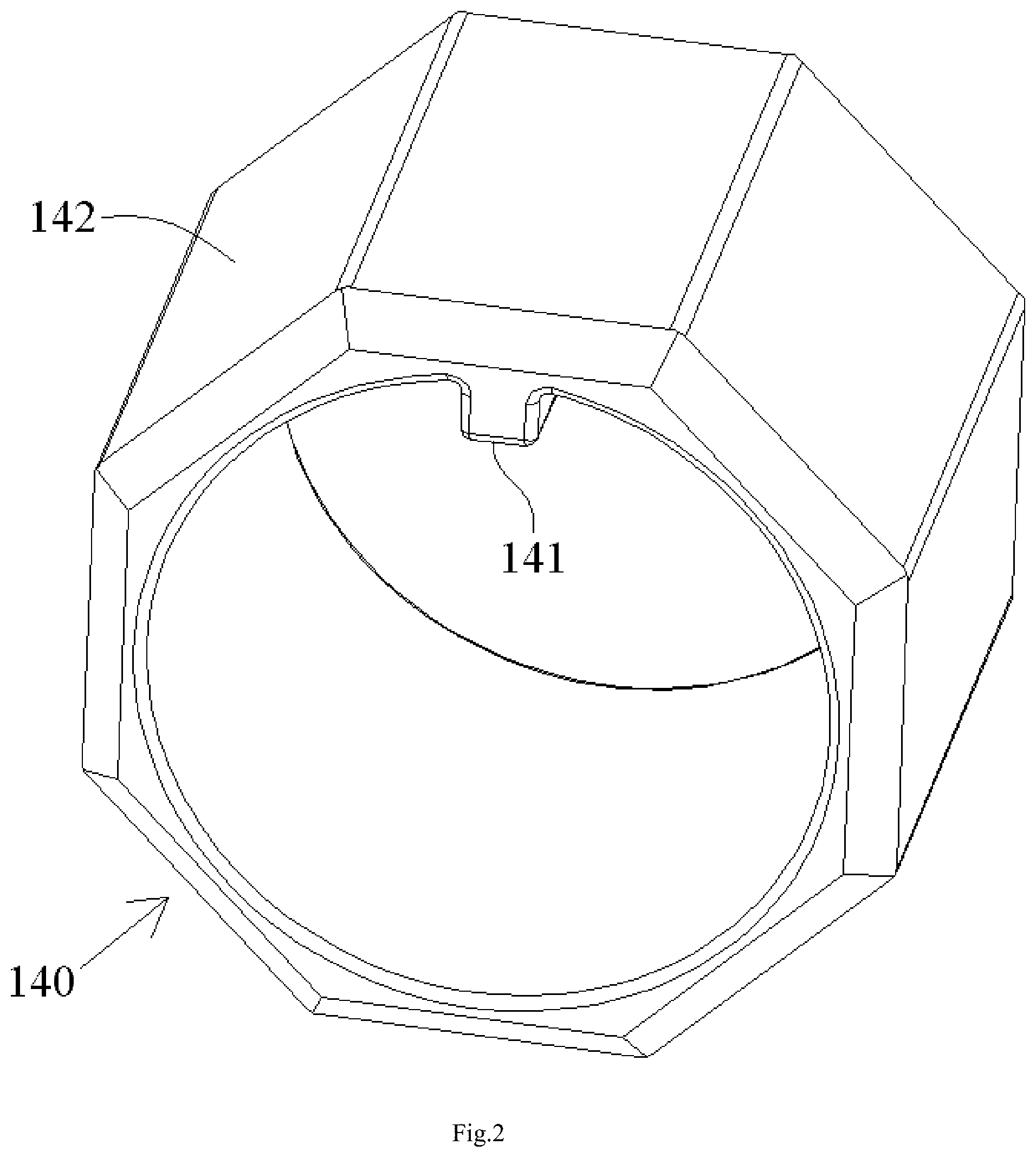
[0041] FIG. 3 is an illustrative perspective view of an alignment sleeve of the fiber optic adapter of FIG. 1;
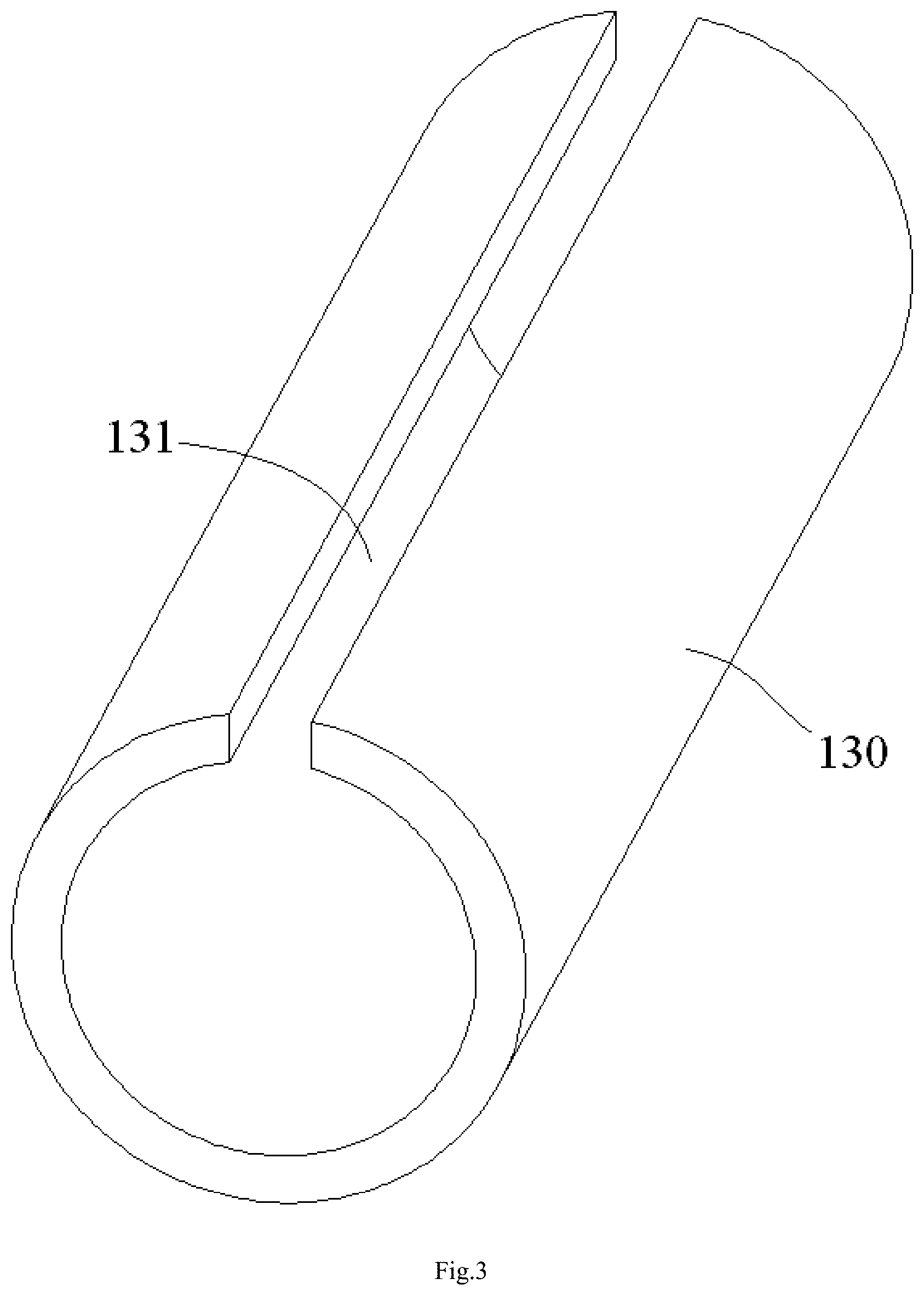
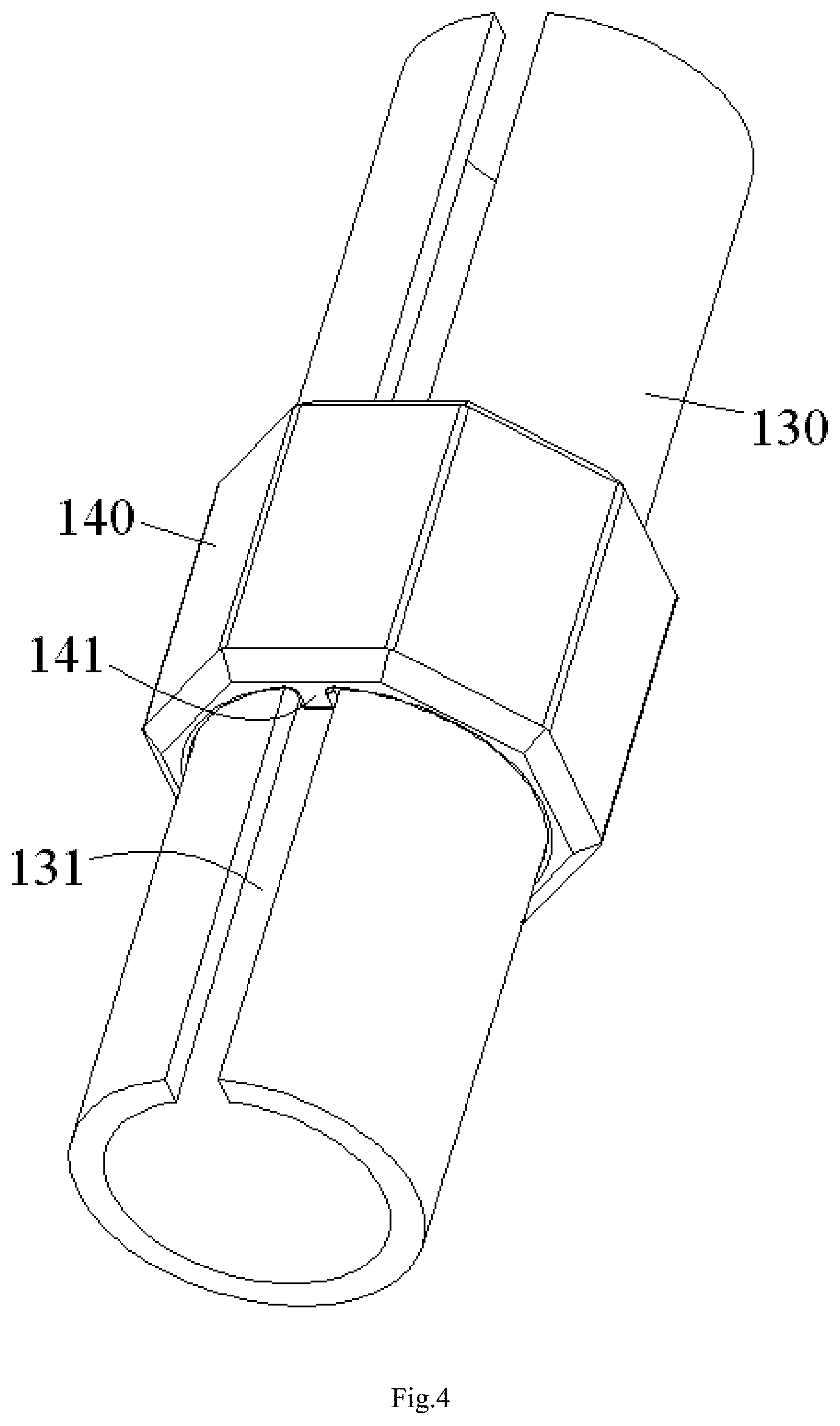
[0042] FIG. 4 is an illustrative view of an alignment sleeve assembly formed by assembling the adjustment element of FIG. 2 to the alignment sleeve of FIG. 3;
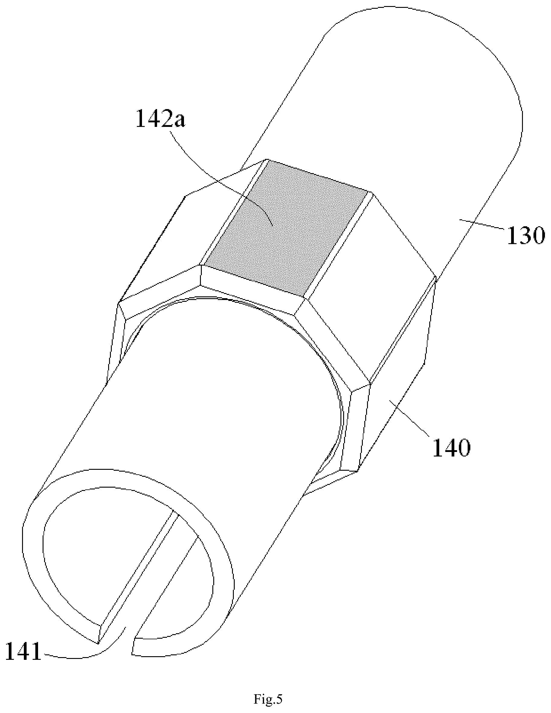
[0043] FIG. 5 is an illustrative view of a first circumferential angle mark formed on an outer surface of the adjustment element of the alignment sleeve assembly of FIG. 4;
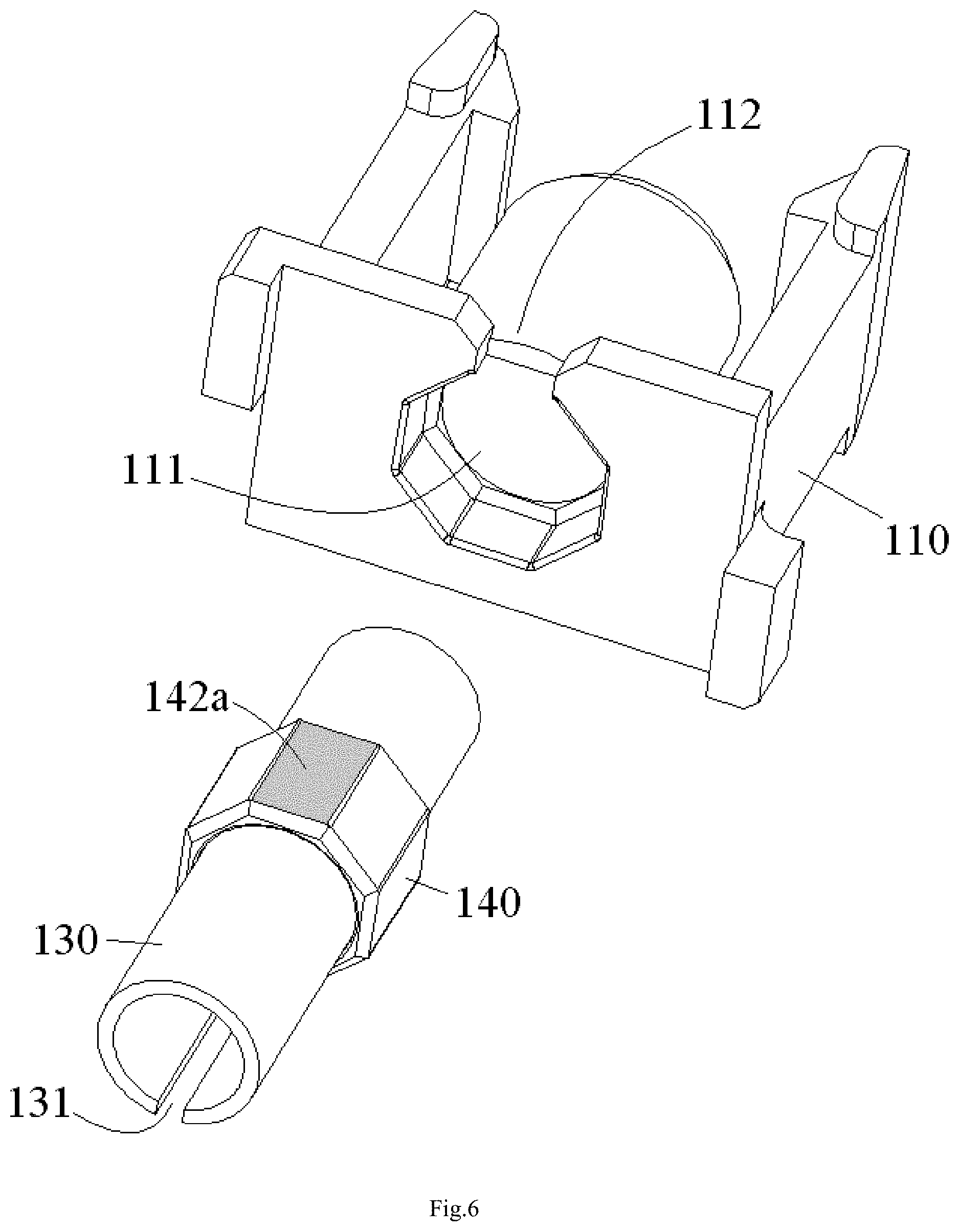
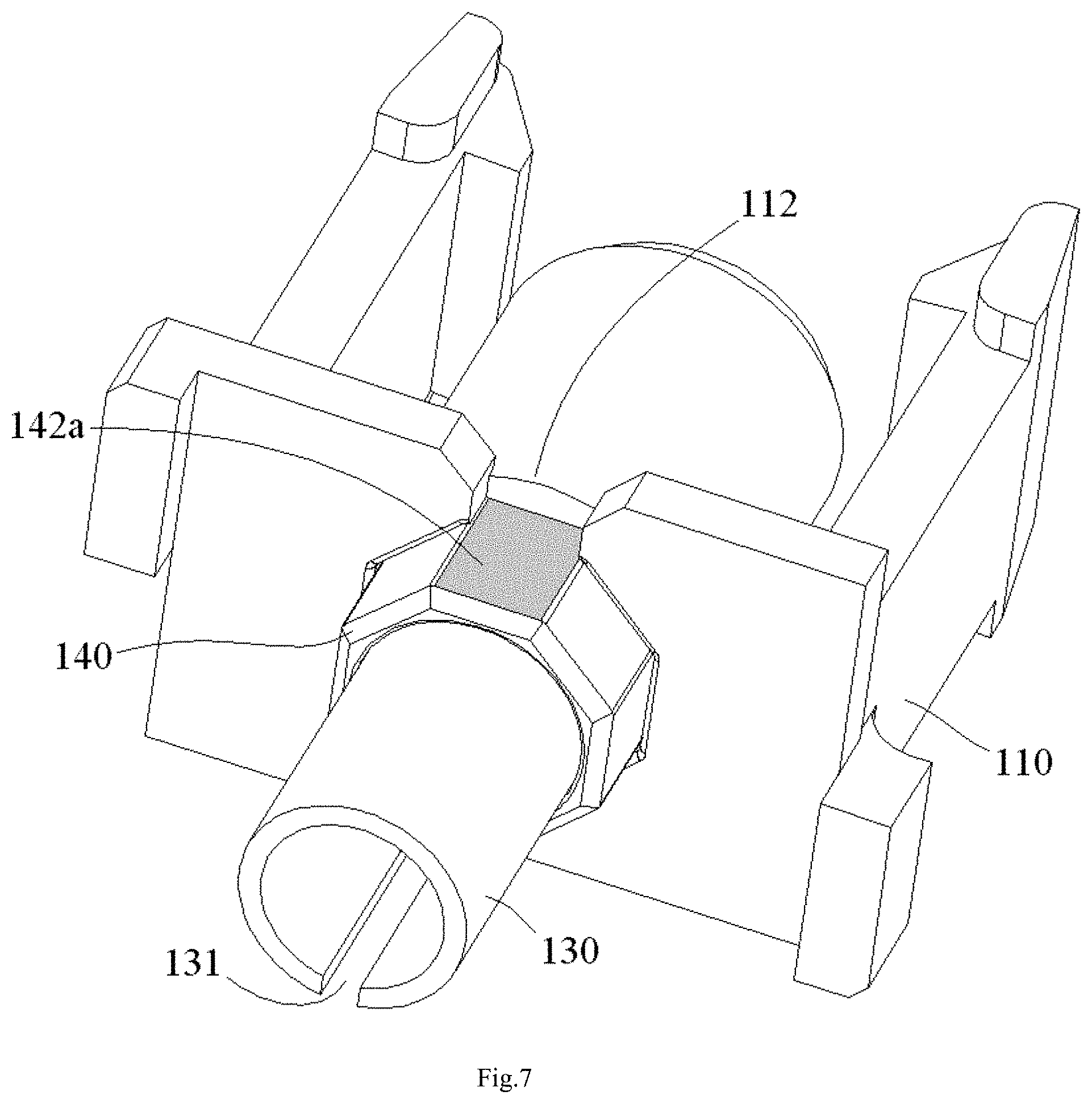
[0044] FIGS. 6 and 7 are illustrative views of mounting the alignment sleeve assembly of FIG. 5 to a first mating retainer;
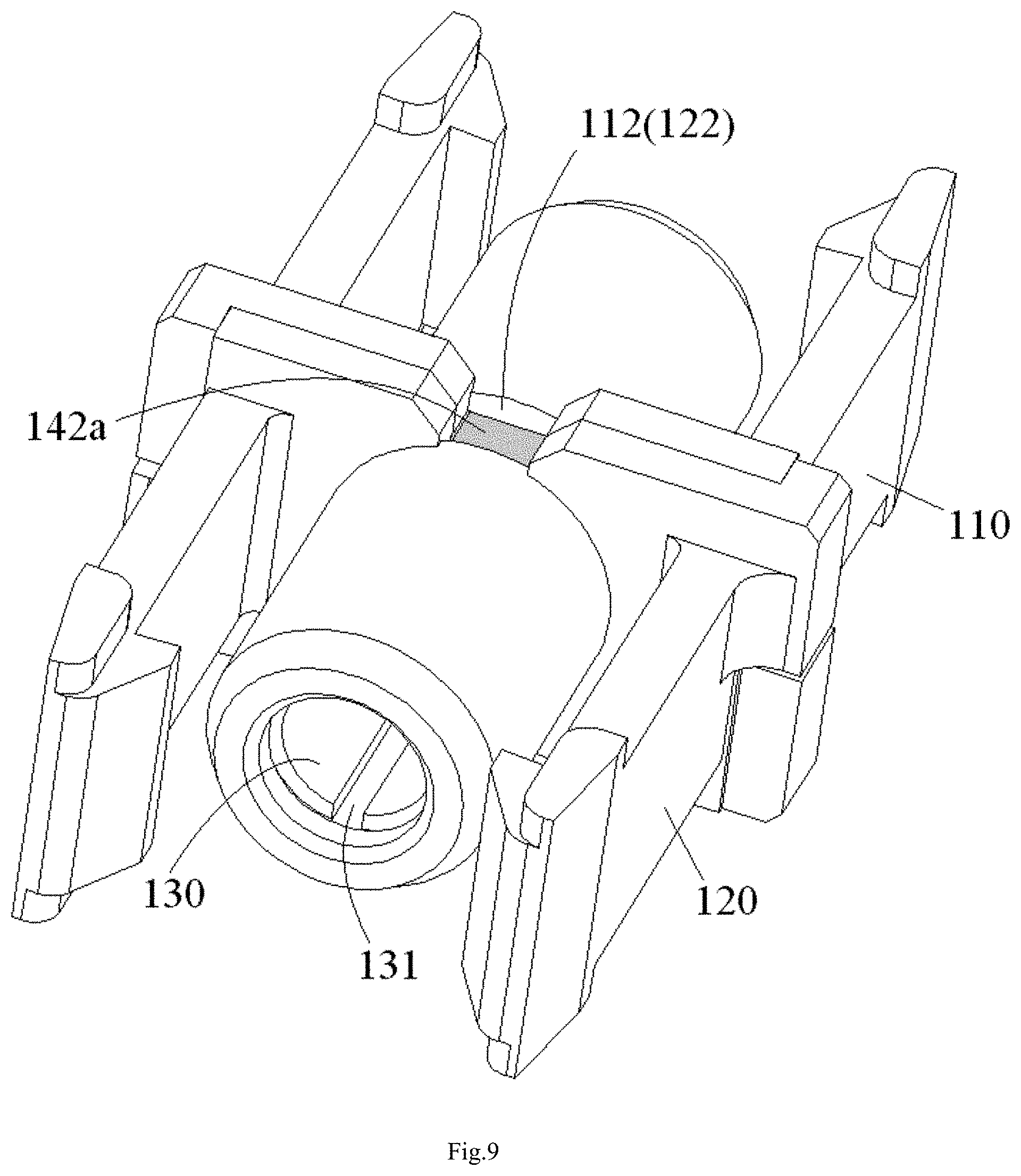
[0045] FIGS. 8 and 9 are illustrative views of assembling the first mating retainer of FIG. 7 to a second mating retainer;
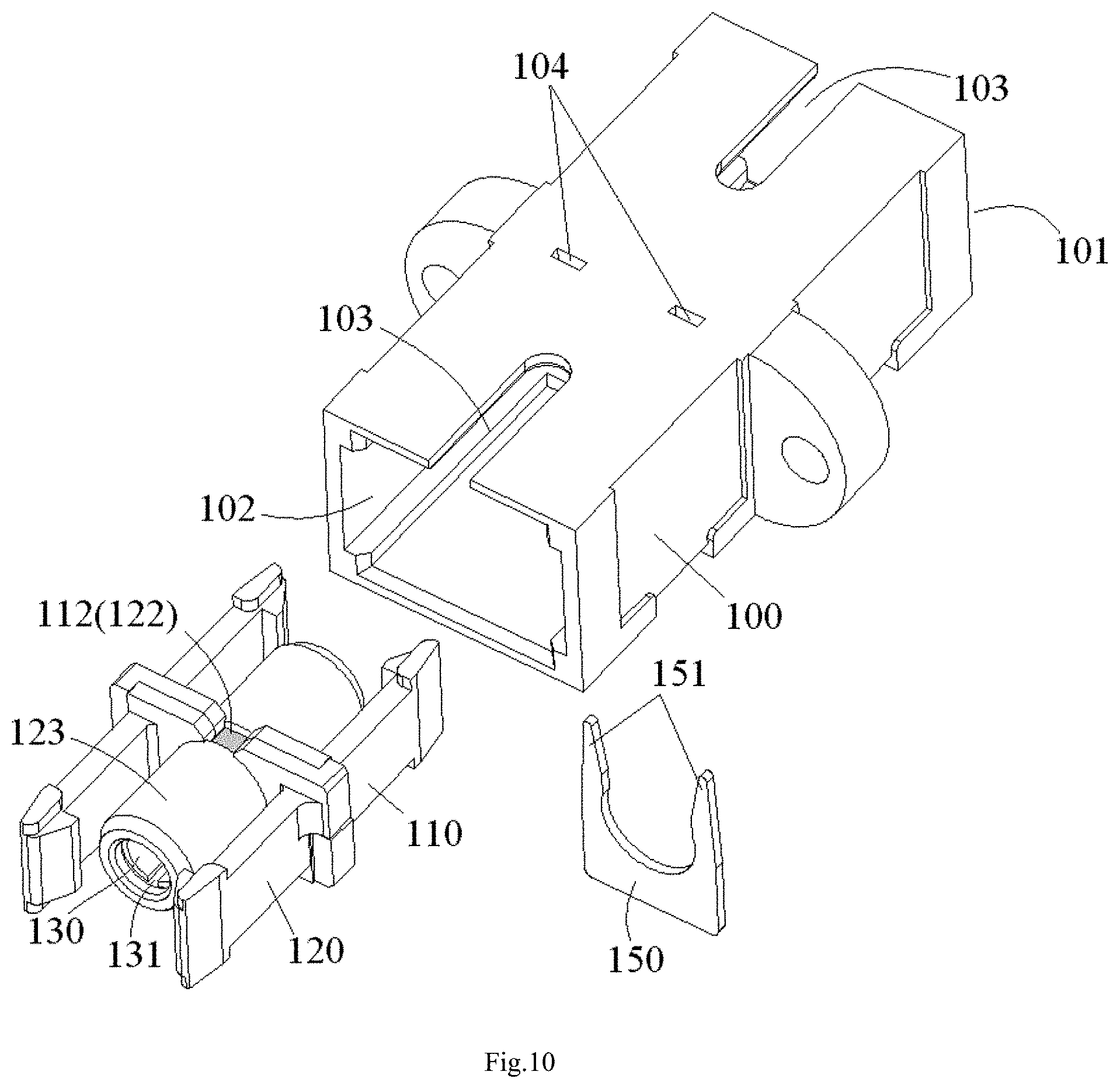
[0046] FIG. 10 is an illustrative view of mounting the assembled first and second mating retainers of FIG. 9 to a housing;
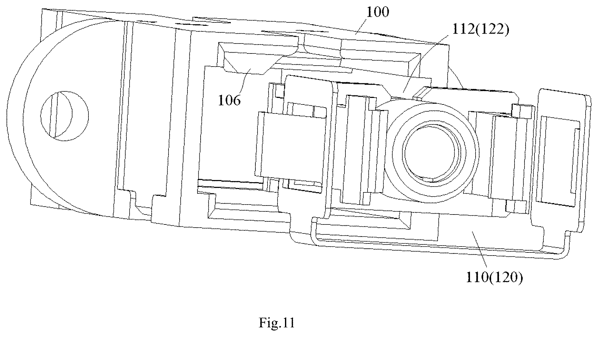
[0047] FIG. 11 shows a foolproof installation structure between the housing and the mating retainer;
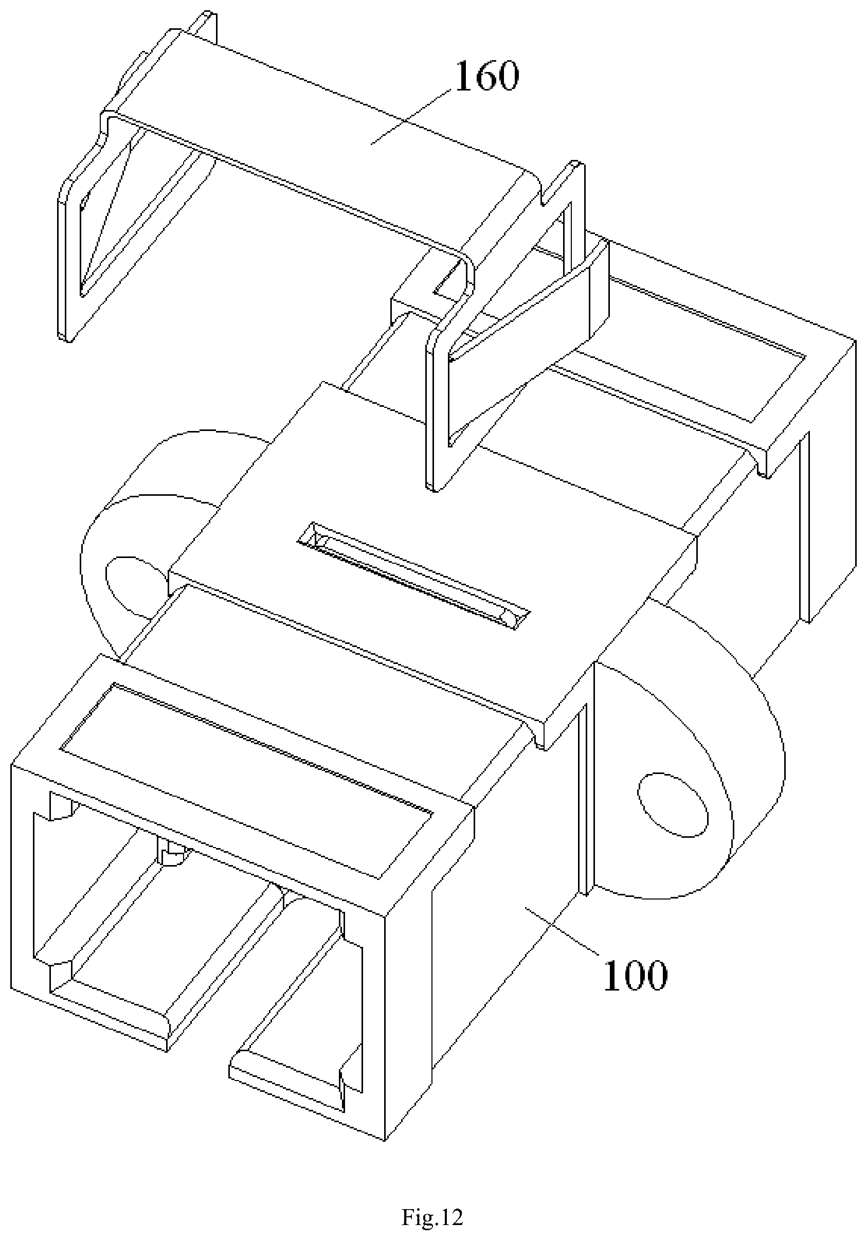
[0048] FIG. 12 is an illustrative view of mounting an elastic snapper on the housing;
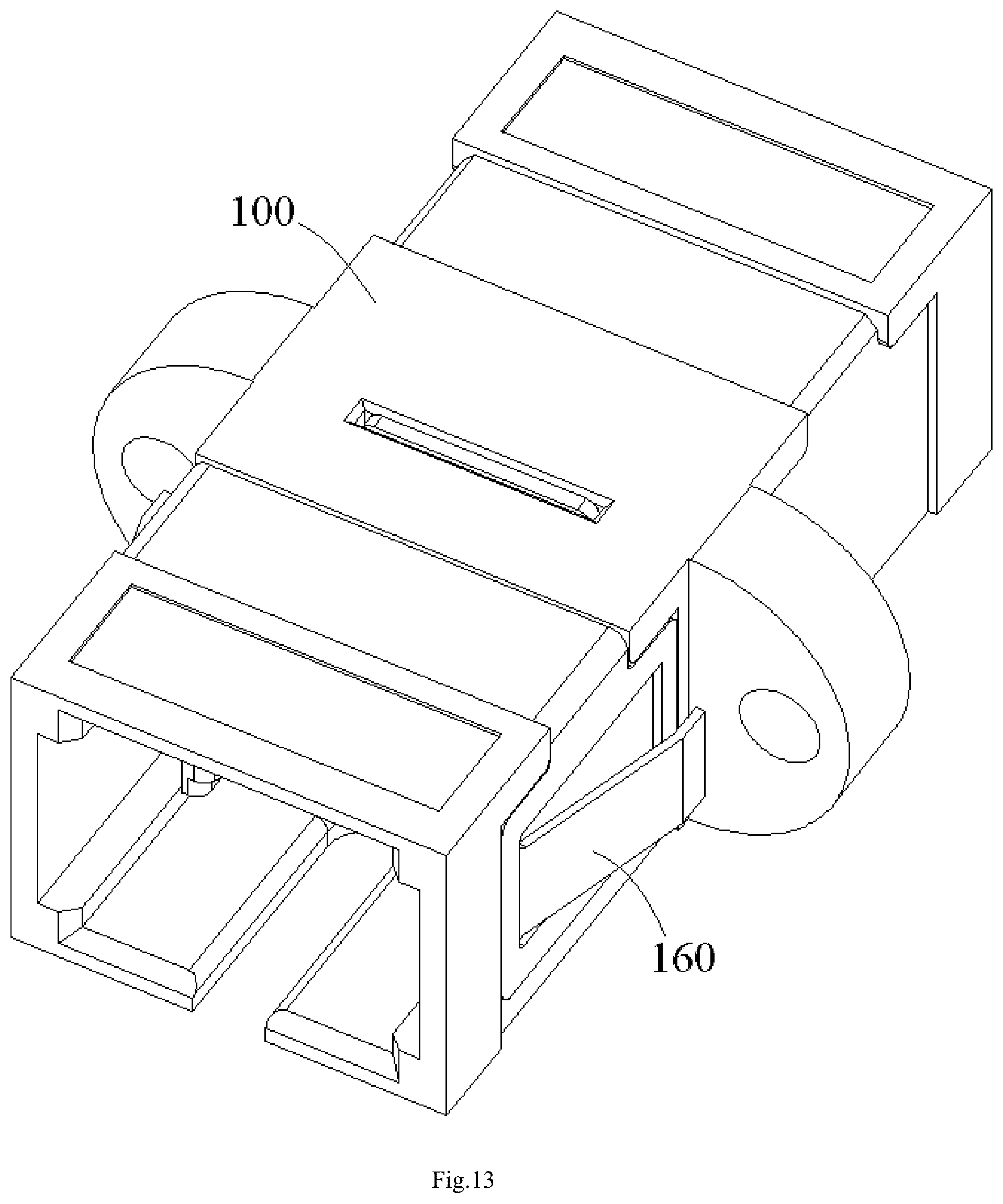
[0049] FIG. 13 is an illustrative perspective view of the assembled fiber optic adapter according to the first exemplary embodiment of the present invention;
[0050] FIG. 14 is an illustrative perspective view of a fiber optic adapter according to a second exemplary embodiment of the present invention, wherein an alignment sleeve assembly is mounted to a first mating retainer;
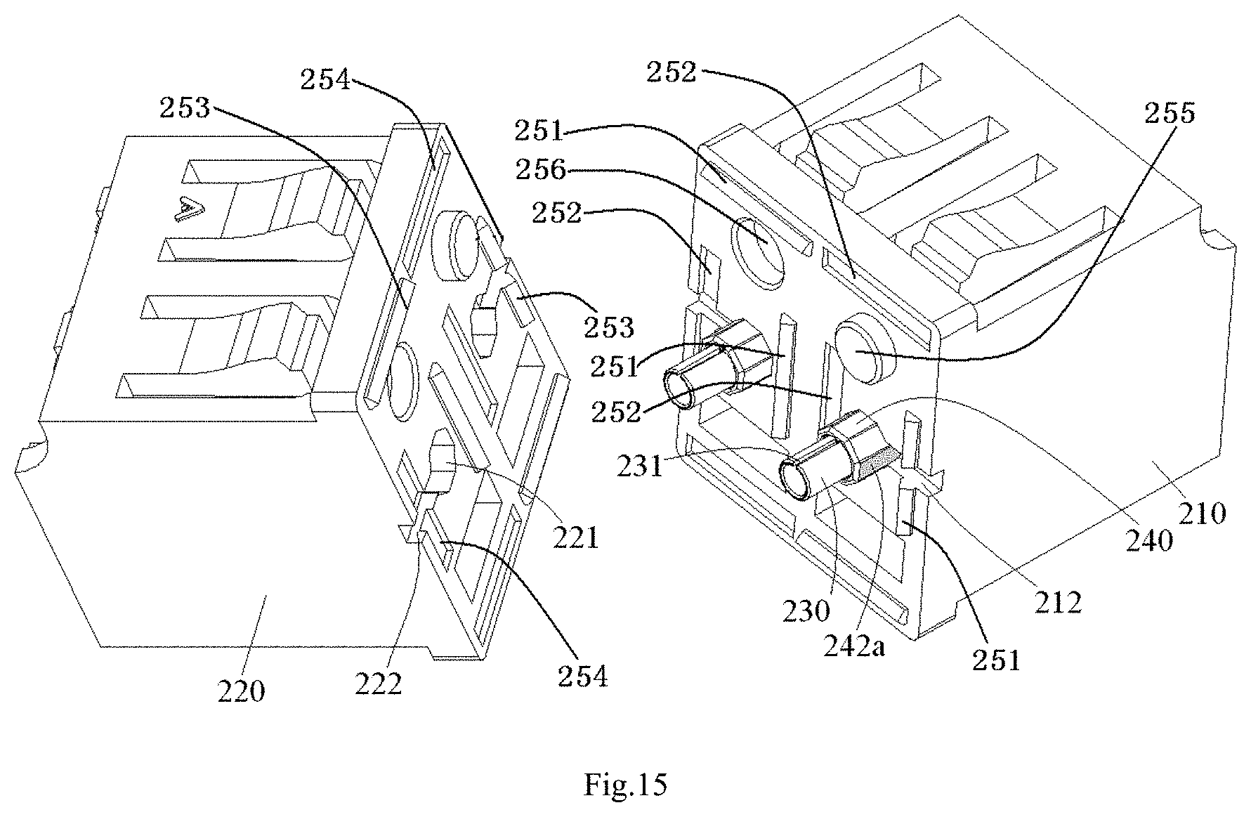
[0051] FIG. 15 is an illustrative view of assembling the first mating retainer of FIG. 14 to a second mating retainer; and
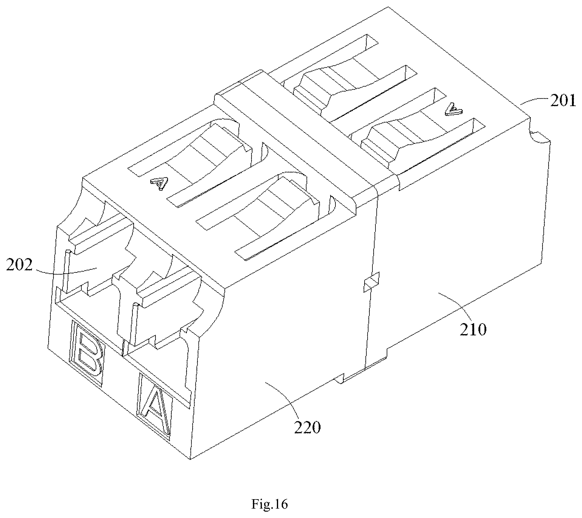
[0052] FIG. 16 is an illustrative perspective view of an assembled fiber optic adapter according to a second exemplary embodiment of the present invention.
DETAILED DESCRIPTION OF PREFERRED EMBODIMENTS OF THE INVENTION
[0053] Exemplary embodiments of the present disclosure will be described hereinafter in detail with reference to the attached drawings, wherein the like reference numerals refer to the like elements. The present disclosure may, however, be embodied in many different forms and should not be construed as being limited to the embodiment set forth herein; rather, these embodiments are provided so that the present disclosure will be thorough and complete, and will fully convey the concept of the disclosure to those skilled in the art.
[0054] In the following detailed description, for purposes of explanation, numerous specific details are set forth in order to provide a thorough understanding of the disclosed embodiments. It will be apparent, however, that one or more embodiments may be practiced without these specific details. In other instances, well-known structures and devices are schematically shown in order to simplify the drawing.
[0055] According to a general concept of the present invention, there is provided a fiber optic adapter, comprising: a mating retainer; an alignment sleeve received in the mating retainer, a ferrule of a fiber optic connector being adapted to be inserted into the alignment sleeve through an insertion port of the fiber optic adapter; and an adjustment element configured to adjust a circumferential angle of the alignment sleeve relative to the mating retainer to a predetermined circumferential angle and hold the alignment sleeve at the predetermined circumferential angle relative to the mating retainer.
[0056] According to another general concept of the present invention, there is provided an alignment sleeve assembly, comprising: an alignment sleeve adapted to be received in a mating retainer of a fiber optic adapter; and an adjustment element configured to adjust a circumferential angle of the alignment sleeve relative to the mating retainer to a predetermined circumferential angle and hold the alignment sleeve at the predetermined circumferential angle relative to the mating retainer.
First Embodiment
[0057] FIGS. 1-13 show a fiber optic adapter according to a first exemplary embodiment of the present invention.
[0058] FIG. 1 is an illustrative exploded view of the fiber optic adapter according to a first exemplary embodiment of the present invention.
[0059] As shown in FIG. 1, it shows a LC type of fiber optic adapter. The fiber optic adapter mainly comprises a housing 100, a mating retainer 110, 120, an alignment sleeve 130 and an adjustment element 140.
[0060] As shown in FIG. 1, the mating retainer 110, 120 comprises a first mating retainer 110 and a second mating retainer 120 capable of being assembled together. The mating retainer 110, 120 is configured to receive the alignment sleeve 130 therein and lock coupled fiber optic connectors (not shown) in place. A ferrule of one of the fiber optic connector is adapted to be inserted into the alignment sleeve 130 through an insertion port 101, 102 of the fiber optic adapter. In this way, fiber cores of the fiber optic connectors are coupled with each other in the alignment sleeve 130.
[0061] FIG. 2 is an illustrative perspective view of an adjustment element 140 of the fiber optic adapter of FIG. 1; FIG. 3 is an illustrative perspective view of an alignment sleeve 130 of the fiber optic adapter of FIG. 1; FIG. 4 is an illustrative view of an alignment sleeve assembly formed by assembling the adjustment element 140 of FIG. 2 to the alignment sleeve 130 of FIG. 3.
[0062] As shown in FIGS. 1-4, in an embodiment, the adjustment element 140 is configured to adjust a circumferential angle of the alignment sleeve 130 relative to the mating retainer 110, 120 to a predetermined circumferential angle and hold the alignment sleeve 130 at the predetermined circumferential angle relative to the mating retainer 110, 120.
[0063] In an embodiment, when the alignment sleeve 130 is held at the predetermined circumferential angle relative to the mating retainer 110, 120, an alignment error between fiber cores of fibers, which are inserted into the alignment sleeve 130 fiber optic adapter, of a pair of fiber optic connectors is minimal, that is, an insertion loss is minimal. In this way, it is possible to minimize the insertion loss of the fiber optic connectors by adjusting and positioning the circumferential angle of the alignment sleeve 130 with respect to the mating retainer 110, 120.
[0064] In the first embodiment shown in FIGS. 1-13, only a single alignment sleeve 130 is received in the mating retainer 110, 120. The alignment sleeve 130 is configured to align ferrules of the pair of fiber optic connectors to be coupled. Thereby, the fiber optic adapter of FIG. 1 is adapted to couple only a pair of fiber optic connectors at the same time. However, the present invention is not limited to this; the fiber optic adapter may be configured to couple a plurality of pairs of fiber optic connectors at the same time.
[0065] Hereafter, it will describe in detail features and assembling operation of components of the optical fiber adapter with reference to drawings.
[0066] As shown in FIGS. 2-4, in an embodiment, the adjustment element 140 is adapted to be sleeved on the alignment sleeve 130. A radial protrusion 141 is formed on an inner wall of the adjustment element 140 and adapted to be inserted into a longitudinal slot 131 of the alignment sleeve 130, so that the alignment sleeve 130 is capable of being rotated with the alignment element 140, and the circumferential angle of the alignment sleeve 130 relative to the mating retainer 110, 120 is adjusted by rotating the adjustment element 140.
[0067] In an exemplary embodiment of the present invention, the radial protrusion 141 of the adjustment element 140 has a width in a circumferential direction equal to or slightly less than a width of the longitudinal slot 131 of the alignment sleeve 130 in the circumferential direction. In this way, once the radial protrusion 141 of the adjustment element 140 is inserted into the longitudinal slot 131 of the alignment sleeve 130, the alignment sleeve 130 is unable to be rotated in a circumferential direction relative to the adjustment element 140, or is only able to be rotated in a very small angle range in the circumferential direction relative to the adjustment element 140, for example, is only able to be rotated in a range of .+-.30 degrees, preferably, in a range of .+-.20 degrees, more preferably, in a range of .+-.10 degrees.
[0068] FIG. 5 is an illustrative view of a first circumferential angle mark 142a formed on an outer surface of the adjustment element 140 of the alignment sleeve assembly of FIG. 4.
[0069] As shown in FIGS. 4 and 5, in an embodiment, before the alignment sleeve 130 is mounted to the mating retainer 110, 120, the alignment sleeve 130 is adjusted to the optimum circumferential angle, at which the insertion loss of the optical fiber connectors is minimal, by the adjustment element 140.
[0070] FIGS. 6 and 7 are illustrative views of mounting the alignment sleeve assembly of FIG. 5 to the first mating retainer 110; FIGS. 8 and 9 are illustrative views of assembling the first mating retainer 110 of FIG. 7 to the second mating retainer 120.
[0071] As shown in FIGS. 5-9, in an embodiment, after the alignment sleeve 130 is adjusted to the optimum circumferential angle at which the insertion loss of the optical fiber connectors is minimal, a first circumferential angle mark 142a is provided on the outer surface 142 of the adjustment element 140. The first circumferential angle mark 142a is used to identify the optimum circumferential angle of the alignment sleeve 130 relative to the mating retainer 110. In an embodiment, when the alignment sleeve 130 is adjusted to the optimum circumferential angle by the adjustment element 140, the first circumferential angle mark 142a of the adjustment element 140 should be aligned to a second circumferential angle mark 112, 122 formed on the mating retainer 110, 120. In this way, during the alignment sleeve assembly of FIG. 5 is mounted to the mating retainer 110, 120, as long as the first circumferential angle mark 142a of the adjustment element 140 is aligned to the second circumferential angle mark 112, 122 of the mating retainer 110, 120, it may ensure that the alignment sleeve 130 is positioned at the optimum circumferential angle, at which the insertion loss of the optical fiber connectors is minimal, with respect to the mating retainer 110.
[0072] In an exemplary embodiment of the present invention, as shown in FIGS. 5-9, the adjustment element 140 is constructed as a polygonal prism with a polygon cross section exhibiting, for example, triangle, quadrilateral, pentagon, hexagon or any other shape with more edges. In another embodiment, the adjustment element 140 may have but not limited to a regular polygon cross section. A positioning slot 111, 121, corresponding to an outer profile of the adjustment element 140, is formed in mating retainer 110, 120. The adjustment element 140 is adapted to be fixed in positioning slot 111, 121 of the mating retainer 110, 120, so as to hold the alignment sleeve 130 at the optimum circumferential angle relative to the mating retainer 110, 120.
[0073] Please be noted that the present invention is not limited to the illustrated embodiment, the adjustment element may be fixed on the mating retainer by any other suitable way. For example, in another embodiment, the adjustment element 140 is formed with multiple spline keys; the mating retainer 110, 120 is formed with multiple spline slots. The multiple spline keys of the adjustment element 140 are adapted to be fitted in the multiple spline slots of the mating retainer 110, 120, so as to hold the alignment sleeve 130 at the optimum circumferential angle relative to the mating retainer 110, 120.
[0074] FIG. 10 is an illustrative view of mounting the assembled first and second mating retainers 110, 120 of FIG. 9 to a housing 100.
[0075] As shown in FIGS. 9 and 10, after the first and second mating retainers 110, 120 are assembled together, the entire mating retainer 110, 120 is mounted in the housing 100.
[0076] As shown in FIG. 10, in an embodiment, an alignment slot 103, configured to mate with a sliding block (not shown) on the fiber optic connector, is formed in the housing 100, so as to ensure that the fiber optic connector is inserted into the fiber optic adapter in a correct orientation relative to the fiber optic adapter. When the alignment sleeve 130 is adjusted to and kept at the optimum circumferential angle by the adjustment element 140, the first circumferential angle mark 142a and the second circumferential angle mark 112, 122 are aligned to the alignment slot 103 of the housing 100. In this way, during the mating retainer 110, 120 is mounted to the housing 100, as long as the first circumferential angle mark 142a and the second circumferential angle mark 112, 122 are aligned to the alignment slot 103 of the housing 100, it may ensure that the mating retainer 110, 120 is correctly mounted in the housing 100.
[0077] FIG. 11 shows a foolproof installation structure between the housing 100 and the mating retainer 110, 120.
[0078] As shown in FIG. 11, in an embodiment, in order to prevent the mating retainer 110, 120 from being incorrectly mounted to (for example, reversely mounted to) the housing 100, a foolproof installation structure between the housing 100 and the mating retainer 110, 120 is designed.
[0079] As shown in FIG. 11, in an embodiment, the second circumferential angle mark 112, 122 of the mating retainer 110, 120 comprises a notch formed in the mating retainer 110, 120. A foolproof assembly protrusion 106, configured to mate with the notch of the mating retainer 110, 120, is formed on an inner wall of the housing 100. The mating retainer 110, 120 is allowed to be assembled into the housing 100 only when the foolproof assembly protrusion 106 of the housing 100 is aligned to the notch of the mating retainer 110, 120. In other words, if the foolproof assembly protrusion 106 of the housing 100 is not aligned to the notch of the mating retainer 110, 120, the retainer 110, 120 is not allowed to be assembled into the housing 100. In this way, it may effectively prevent the mating retainer 110, 120 from being incorrectly mounted to (for example, reversely mounted to) the housing 100.
[0080] As shown in FIGS. 1 and 10, the fiber optic adapter may further comprise a fixation element 150 adapted to be mounted on the housing 100 and hold a tube-like body 123 of the mating retainer 110, 120, so as to prevent the mating retainer 110, 120 from being pulled out of the housing 100.
[0081] In an embodiment, the fixation element 150 is inserted into the housing 100 through a slot 105 (see FIG. 1) formed in the housing 100. Two legs of the fixation element 150 are inserted into two holes 104 formed in the housing 100. As a result, the tube-like body 123 of the mating retainer 110, 120 is clamped and fixed by the fixation element 150.
[0082] FIG. 12 is an illustrative view of mounting an elastic snapper 160 on the housing 100; FIG. 13 is an illustrative perspective view of the assembled fiber optic adapter according to the first exemplary embodiment of the present invention.
[0083] As shown in FIGS. 12-13, in an embodiment, the fiber optic adapter may further comprise an elastic snapper 160 mounted on the housing 100 and configured to lock the fiber optic adapter in a fixation installation position.
[0084] In the first embodiment shown in FIGS. 1-13, the mating retainer 110, 120 comprises the first mating retainer 110 and the second mating retainer 120 capable of being assembled together. The positioning slot 111, 121 comprises a first positioning slot 111 and a second positioning slot 121, aligned to each other, formed in mating ends of the first mating retainer 110 and the second mating retainer 120, respectively. The second circumferential angle mark 112, 122 comprises a first notch 112 and a second notch 122, aligned to each other, formed in the mating ends of the first mating retainer 110 and the second mating retainer 120, respectively.
[0085] Also, it should be appreciated that, in some conditions, it is unnecessary to set the insertion loss of the fiber optic connectors inserted into the fiber optic adapter to be minimal, but it is necessary to maintain the longitudinal slot 131 of the alignment sleeve 130 at a specified circumferential angle (a predetermined orientation) with respect to the mating retainer 110, 120. In this case, it is also possible to use the adjustment element 130 to adjust the alignment sleeve 130 to the specified circumferential angle and kept at the specified circumferential angle.
Second Embodiment
[0086] FIGS. 14-16 show a fiber optic adapter according to a second exemplary embodiment of the present invention.
[0087] FIG. 14 is an illustrative perspective view of a fiber optic adapter according to a second exemplary embodiment of the present invention, wherein an alignment sleeve assembly is mounted to a first mating retainer 210; FIG. 15 is an illustrative view of assembling the first mating retainer 210 of FIG. 14 to a second mating retainer 220; and FIG. 16 is an illustrative perspective view of an assembled fiber optic adapter according to a second exemplary embodiment of the present invention.
[0088] As shown in FIGS. 14-16, in the second embodiment, the fiber optic adapter is adapted to couple a plurality of pairs of fiber optic connectors at the same time. A plurality of alignment sleeves 230, configured to align ferrules of the pairs of fiber optic connectors, are received in the mating retainer 210, 220.
[0089] Also, in the second embodiment shown in FIGS. 14-16, the fiber optic adapter does not comprise a housing, since the mating retainer 210, 220 is served as a body of the fiber optic adapter and is directly exposed outside.
[0090] In the second embodiment shown in FIGS. 14-16, the mating retainer 210, 220 comprises a first mating retainer 210 and a second mating retainer 220 capable of being assembled together. The mating retainer 210, 220 is configured to receive the alignment sleeves 130 therein and lock coupled fiber optic connectors (not shown) in place. A ferrule of a fiber optic connector is adapted to be inserted into the alignment sleeve 230 through an insertion port 201, 202 of the fiber optic adapter. In this way, fiber cores of the fiber optic connectors are coupled with each other in the alignment sleeve 230.
[0091] In the second embodiment shown in FIGS. 14-16, the adjustment element 240 is configured to adjust a circumferential angle of the alignment sleeve 230 relative to the mating retainer 210, 220 to a predetermined circumferential angle and hold the alignment sleeve 230 at the predetermined circumferential angle relative to the mating retainer 210, 220.
[0092] In the second embodiment shown in FIGS. 14-16, when the alignment sleeve 230 is held at the predetermined circumferential angle relative to the mating retainer 210, 220, an alignment error between fiber cores of fibers, inserted into the alignment sleeve 130 fiber optic adapter, of a pair of fiber optic connectors is minimal, that is, an insertion loss is minimal. In this way, it is possible to minimize the insertion loss of the fiber optic connectors by adjusting and positioning the circumferential angle of the alignment sleeve 230 with respect to the mating retainer 210, 220.
[0093] Hereafter, it will describe in detail features and operation of assembling components of the optical fiber adapter with reference to drawings.
[0094] In the second embodiment shown in FIGS. 14-16, the adjustment element 240 is adapted to be sleeved on the alignment sleeve 230. A radial protrusion 241 is formed on an inner wall of the adjustment element 240 and adapted to be inserted into a longitudinal slot 231 of the alignment sleeve 230, so that the alignment sleeve 230 is capable of being rotated with the alignment element 240, and the circumferential angle of the alignment sleeve 230 relative to the mating retainer 210, 220 is capable of being adjusted by rotating the adjustment element 240.
[0095] In an exemplary embodiment of the present invention, the radial protrusion 241 of the adjustment element 240 has a width in a circumferential direction equal to or slightly less than a width of the longitudinal slot 231 of the alignment sleeve 230 in the circumferential direction. In this way, once the radial protrusion 241 of the adjustment element 240 is inserted into the longitudinal slot 231 of the alignment sleeve 230, the alignment sleeve 230 is unable to be rotated in the circumferential direction relative to the adjustment element 240, or is only able to be rotated in a very small angle range in the circumferential direction relative to the adjustment element 240, for example, is only able to be rotated in a range of .+-.30 degrees, preferably, in a range of .+-.20 degrees, more preferably, in a range of .+-.10 degrees.
[0096] In the second embodiment shown in FIGS. 14-16, before the alignment sleeve 230 is mounted to the mating retainer 210, 220, the alignment sleeve 230 is adjusted to the optimum circumferential angle, at which the insertion loss of the optical fiber connectors is minimal, by the adjustment element 240.
[0097] In the second embodiment shown in FIGS. 14-16, after the alignment sleeve 230 is adjusted to the optimum circumferential angle at which the insertion loss of the optical fiber connectors is minimal, a first circumferential angle mark 242a is provided on the outer surface 242 of the adjustment element 240. The first circumferential angle mark 242a is used to identify the optimum circumferential angle of the alignment sleeve 230 relative to the mating retainer 210. In an embodiment, when the alignment sleeve 230 is adjusted to the optimum circumferential angle by the adjustment element 240, the first circumferential angle mark 242a of the adjustment element 240 should be aligned to a second circumferential angle mark 212, 222 formed on the mating retainer 210, 220. In this way, during the alignment sleeve assembly of FIG. 14 is mounted to the mating retainer 210, 220, as long as the first circumferential angle mark 242a of the adjustment element 240 is aligned to the second circumferential angle mark 212, 222 of the mating retainer 210, 220, it may ensure that the alignment sleeve 230 is positioned at the optimum circumferential angle, at which the insertion loss of the optical fiber connectors is minimal, with respect to the mating retainer 210, 220.
[0098] In the second embodiment shown in FIGS. 14-16, the adjustment element 240 is constructed as a polygonal prism with a polygon cross section exhibiting, for example, triangle, quadrilateral, pentagon, hexagon or any other shape with more edges. In another embodiment, the adjustment element 240 may have but not limited to a regular polygon cross section. A positioning slot 211, 221, corresponding to an outer profile of the adjustment element 240, is formed in mating retainer 210, 220. The adjustment element 240 is adapted to be fixed in positioning slot 211, 221 of the mating retainer 210, 220, so as to hold the alignment sleeve 230 at the optimum circumferential angle relative to the mating retainer 210, 220.
[0099] Please be noted that the present invention is not limited to the illustrated embodiment, the adjustment element may be fixed on the mating retainer by any other suitable way. For example, in another embodiment, the adjustment element 240 is formed with multiple spline keys; the mating retainer 210, 220 is formed with multiple spline slots. The multiple spline keys of the adjustment element 240 are adapted to be fitted in the multiple spline slots of the mating retainer 210, 220, so as to hold the alignment sleeve 230 at the optimum circumferential angle relative to the mating retainer 210, 220.
[0100] In the second embodiment shown in FIGS. 14-16, the second circumferential angle mark 212, 222 of the mating retainer 210, 220 is a notch formed in the mating retainer 210, 220.
[0101] In the second embodiment shown in FIGS. 14-16, the mating retainer 210, 220 comprises a first mating retainer 210 and a second mating retainer 220 capable of being assembled together. The positioning slot 211, 221 comprises a first positioning slot 211 and a second positioning slot 221, aligned to each other, formed in mating ends of the first mating retainer 210 and the second mating retainer 220, respectively. The second circumferential angle mark 212, 222 comprises a first notch 212 and a second notch 222, aligned to each other, formed in the mating ends of the first mating retainer 210 and the second mating retainer 220, respectively.
[0102] The first mating retainer 210 and the second mating retainer 220 are coupled with each other in a snap-fit manner. In an exemplary embodiment, the first mating retainer 210 is provided with a plurality of first engagement protrusions 251 and a plurality of first engagement recesses 252, and the second mating retainer 220 is provided with a plurality of second engagement protrusions 253, which are engaged with the plurality of first engagement recesses 252, respectively, and a plurality of second engagement recesses 254, which are engaged with the plurality of first engagement protrusions 252, respectively. Furthermore, the first mating retainer 210 is provided with at least one first guiding protrusions 255 and at least one first guiding recesses 256, and the second mating retainer 220 is provided with at least one second guiding protrusions, which are engaged with the plurality of first engagement recesses 256, respectively, and at least one second guiding recesses, which are engaged with the plurality of first engagement protrusions 255, respectively.
[0103] Also, it should be appreciated that, in some conditions, it is unnecessary to set the insertion loss of the fiber optic connectors inserted into the fiber optic adapter to be minimal, but it is necessary to maintain the longitudinal slot 231 of the alignment sleeve 1230 at a specified circumferential angle (a predetermined orientation) with respect to the mating retainer 210, 220. In this case, it is also possible to use the adjustment element 230 to adjust the alignment sleeve 230 to the specified circumferential angle and kept at the specified circumferential angle.
[0104] It should be appreciated for those skilled in this art that the above embodiments are intended to be illustrated, and not restrictive. For example, many modifications may be made to the above embodiments by those skilled in this art, and various features described in different embodiments may be freely combined with each other without conflicting in configuration or principle.
[0105] Although several exemplary embodiments have been shown and described, it would be appreciated by those skilled in the art that various changes or modifications may be made in these embodiments without departing from the principles and spirit of the disclosure, the scope of which is defined in the claims and their equivalents.
[0106] As used herein, an element recited in the singular and proceeded with the word "a" or "an" should be understood as not excluding plural of said elements or steps, unless such exclusion is explicitly stated. Furthermore, references to "one embodiment" of the present invention are not intended to be interpreted as excluding the existence of additional embodiments that also incorporate the recited features. Moreover, unless explicitly stated to the contrary, embodiments "comprising" or "having" an element or a plurality of elements having a particular property may include additional such elements not having that property.
* * * * *
D00000
D00001
D00002
D00003
D00004
D00005
D00006
D00007
D00008
D00009
D00010
D00011
D00012
D00013
D00014

D00015
D00016
XML
uspto.report is an independent third-party trademark research tool that is not affiliated, endorsed, or sponsored by the United States Patent and Trademark Office (USPTO) or any other governmental organization. The information provided by uspto.report is based on publicly available data at the time of writing and is intended for informational purposes only.
While we strive to provide accurate and up-to-date information, we do not guarantee the accuracy, completeness, reliability, or suitability of the information displayed on this site. The use of this site is at your own risk. Any reliance you place on such information is therefore strictly at your own risk.
All official trademark data, including owner information, should be verified by visiting the official USPTO website at www.uspto.gov. This site is not intended to replace professional legal advice and should not be used as a substitute for consulting with a legal professional who is knowledgeable about trademark law.