Drying System
CHOI; Jae Hoon ; et al.
U.S. patent application number 16/473557 was filed with the patent office on 2020-05-07 for drying system. The applicant listed for this patent is LG CHEM, LTD.. Invention is credited to Jae Hoon CHOI, Won Chan PARK.
| Application Number | 20200141641 16/473557 |
| Document ID | / |
| Family ID | 62709989 |
| Filed Date | 2020-05-07 |


| United States Patent Application | 20200141641 |
| Kind Code | A1 |
| CHOI; Jae Hoon ; et al. | May 7, 2020 |
DRYING SYSTEM
Abstract
The present invention relates to a drying system, and according to one aspect of the present invention, there is provided a drying system comprising a transfer conveyor for transporting particles, a particle dispersing device including a rotary member provided at one side of the transfer conveyor and having a rotation center, a drive part for rotating the rotary member and a particle supply part mounted on the rotary member having particles stored therein, and a heating part for drying the particles on the transfer conveyor in a transfer process, wherein the heating part comprises a heat exchanger and a blast fan, and is provided such that air discharged from the blast fan is supplied to the transfer conveyor after passing through the heat exchanger.
| Inventors: | CHOI; Jae Hoon; (Daejeon, KR) ; PARK; Won Chan; (Daejeon, KR) | ||||||||||
| Applicant: |
|
||||||||||
|---|---|---|---|---|---|---|---|---|---|---|---|
| Family ID: | 62709989 | ||||||||||
| Appl. No.: | 16/473557 | ||||||||||
| Filed: | December 21, 2017 | ||||||||||
| PCT Filed: | December 21, 2017 | ||||||||||
| PCT NO: | PCT/KR2017/015181 | ||||||||||
| 371 Date: | June 25, 2019 |
| Current U.S. Class: | 1/1 |
| Current CPC Class: | F26B 25/002 20130101; B65G 15/00 20130101; F26B 3/06 20130101; F26B 17/04 20130101; F26B 21/04 20130101; B65G 43/08 20130101 |
| International Class: | F26B 3/06 20060101 F26B003/06; F26B 17/04 20060101 F26B017/04; F26B 21/04 20060101 F26B021/04; F26B 25/00 20060101 F26B025/00; B65G 43/08 20060101 B65G043/08 |
Foreign Application Data
| Date | Code | Application Number |
|---|---|---|
| Dec 26, 2016 | KR | 10-2016-0178853 |
Claims
1. A drying system comprising: a transfer conveyor for transporting particles; a particle dispersing device including a rotary member provided at one side of the transfer conveyor and having a rotation center, a drive part for rotating the rotary member and a particle supply part mounted on the rotary member having particles stored therein; and a heating part for drying the particles on the transfer conveyor in a transfer process, wherein the heating part comprises a heat exchanger and a blast fan, and is provided such that air discharged from the blast fan is supplied to the transfer conveyor after passing through the heat exchanger.
2. The drying system according to claim 1, wherein the heat exchanger is provided such that air passing through the heat exchanger can be distributed across the width direction of the transfer conveyor.
3. The drying system according to claim 1, wherein the heat exchanger is disposed below the transfer conveyor.
4. The drying system according to claim 3, wherein the heat exchanger is elongated along the width direction so as to correspond to the width of the transfer conveyor.
5. The drying system according to claim 1, comprising a control part for controlling the transfer conveyor and the drive part, wherein upon supplying the particles to the transfer conveyor, the control part controls so that the particle supply part rotates with drawing an arc on the basis of the rotation center of the rotary member in a predetermined direction, and when the particle supply part is rotated, the control part stops the transfer conveyor.
6. The drying system according to claim 5, wherein if the rotation of the particle supply part is completed, the control part operates the transfer conveyor such that the loaded particles are transported.
7. The drying system according to claim 5, wherein the control part controls so that the particle supply part rotationally reciprocates in different directions within a predetermined angle range on the basis of the rotation center.
8. The drying system according to claim 1, wherein the particle supply part comprises a belt conveyor.
9. The drying system according to claim 5, wherein the control part controls so that along the width direction of the transfer conveyor, the particles are loaded thicker on both side edges than the center portion.
Description
[0001] The present application is a National Phase entry pursuant to 35 U.S.C. .sctn. 371 of International Application No. PCT/KR2017/015181 filed Dec. 21, 2017, and claims priority to and the benefit of Korean Patent Application No. 10-2016-0178853 filed on Dec. 26, 2016, the disclosures of which are incorporated herein by reference in their entirety.
FIELD
[0002] The present invention relates to a drying system.
BACKGROUND
[0003] A drying process of a particle-based polymer performed through a drying system is carried out through hot air or the like after uniformly dispersing particles on a transfer conveyor. At this time, a spreading oscillator is used to disperse and load the particles evenly on the transfer conveyor along the width direction of the conveyor.
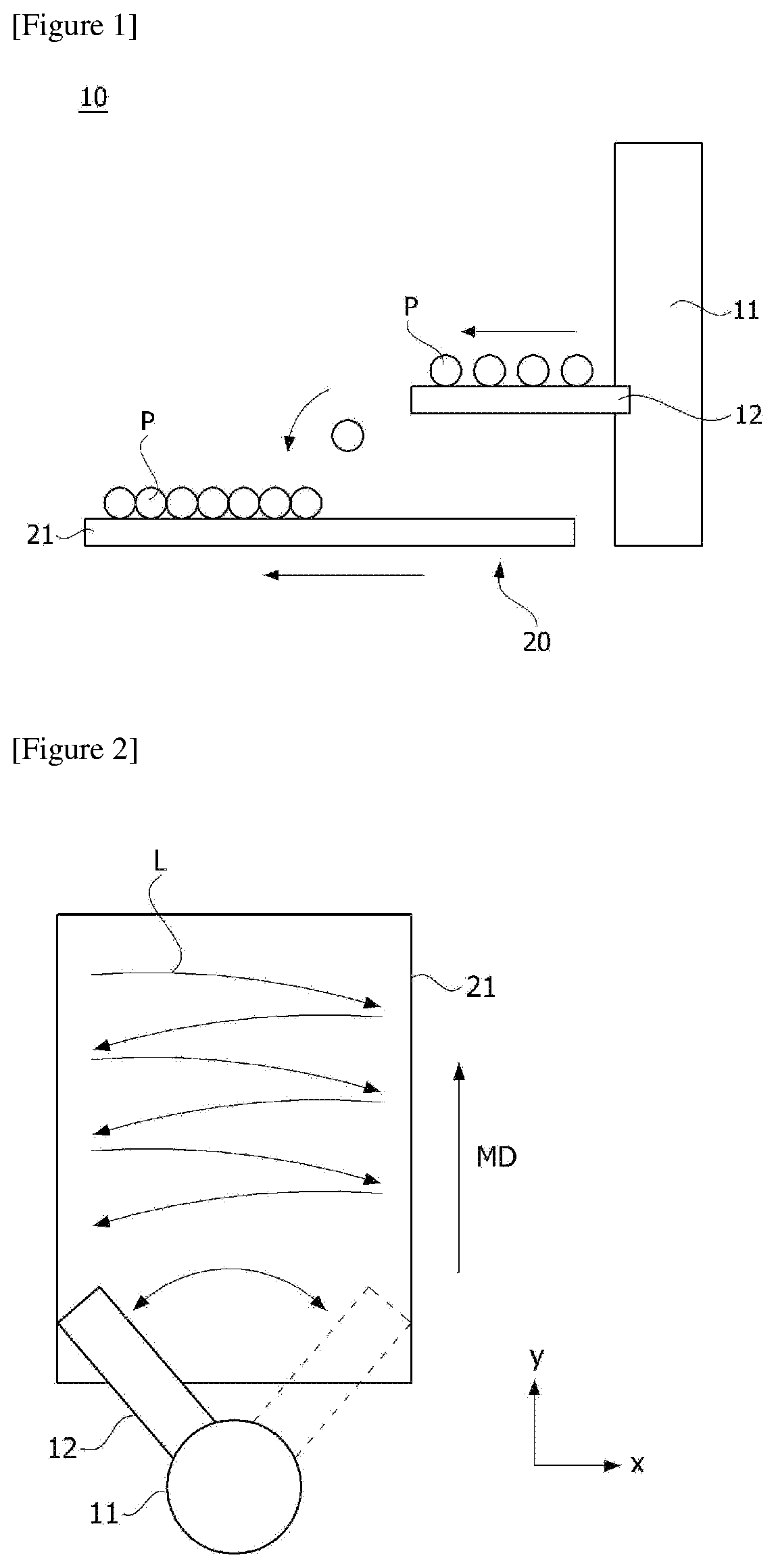
[0004] FIGS. 1 and 2 are schematic diagrams for explaining one operating state of a particle dispersing device (spreading oscillator) (10). The oscillator (10) comprises a rotating shaft (11) and a particle supply part (12) mounted on the rotating shaft (11). At this time, the particle supply part (12) is provided to reciprocate within a predetermined angular range about the rotating shaft (11). In such a structure, a method is used, in which the particle supply part (12) rotationally reciprocates, drawing an arc on the basis of the rotating shaft (11), to spread particles (P) to be dried on a belt (21) of a transfer conveyor (20).
[0005] Furthermore, referring to FIG. 2, repetition times that the particle supply part (12) passes vary for each position along the width direction (x-axis direction) and the conveying direction (y-axis direction) of the belt (21), and thus the particles (P) are unevenly accumulated as a whole.
[0006] For convenience of explanation, it is assumed that the transfer conveyor (20) transports the belt (21) at a rate of 3 cm/s and the oscillator (10) rotationally reciprocates and returns to the initial position every 10 seconds (one-way movement is 5 seconds). Referring to the particle application locus (L) in FIG. 2, particles are sprayed on both sides of the belt (21) every 10 seconds (during this time, the belt is advanced 30 cm). However, particles are sprayed every 5 seconds onto the central portion of the belt (21) (at this time, the belt is advanced 15 cm). In this way, since particles are sprayed while the oscillator (10) reciprocates, it can be confirmed that the interval or time at which the particles are spread at each position is different. The symbol MD (moving direction) indicates the conveying direction of the transfer conveyor.
[0007] Also, if the particles are unevenly dispersed on the belt (21), partially dried particles are generated due to pressure difference or the like upon the drying process, whereby control of the overall physical properties of the product is difficult. Therefore, it is important to uniformly disperse the particles on the transfer conveyor.
[0008] Furthermore, as a heating part for drying particles transported through the transfer conveyor, a hot-air dryer is used, where the hot air passing through a heat exchanger passes to a distribution plate and is supplied toward the transfer conveyor for drying the particles. The distribution plate functions to distribute the hot air evenly along the width direction of the transfer conveyor. In addition, when the heat exchanger is further installed, a difference in pressure before/after passage of the heat exchanger occurs, which causes a decrease in the flow rate of hot air circulating in a drying chamber, so there are limitations on the addition of a heat exchanger. In addition, there are limitations on the addition of a heat exchanger depending on an installation space in the drying chamber.
SUMMARY
[0009] It is an object of the present invention to provide a drying system capable of uniformly dispersing particles on a transfer conveyor and having a uniform flow rate distribution across the width direction of the transfer conveyor with a wide heat transfer area.
[0010] To solve the above object, according to one aspect of the present invention, there is provided a drying system comprising a transfer conveyor for transporting particles, a particle dispersing device including a rotary member provided at one side of the transfer conveyor and having a rotation center, a drive part for rotating the rotary member and a particle supply part mounted on the rotary member having particles stored therein, and a heating part for drying the particles on the transfer conveyor in a transfer process, wherein the heating part comprises a heat exchanger and a blast fan, and is provided such that air discharged from the blast fan is supplied to the transfer conveyor after passing through the heat exchanger.
[0011] Also, the heat exchanger may be provided so that the air passing through the heat exchanger may be distributed across the width direction of the transfer conveyor.
[0012] Furthermore, the heat exchanger may be disposed below the transfer conveyor.
[0013] In addition, the heat exchanger may have a shape elongated along the width direction to correspond to the width of the transfer conveyor.
[0014] Also, the drying system may comprise a control part for controlling the transfer conveyor and the drive part.
[0015] Furthermore, when the particles are supplied to the transfer conveyor, the control part may control so that the particle supply part rotates with drawing an arc on the basis of the rotation center of the rotary member in a predetermined direction.
[0016] In addition, when the particle supply part is rotated, the control part may be provided so as to stop the transfer conveyor.
[0017] Also, when the rotation of the particle supply part is completed, the control part may operate the transfer conveyor such that the loaded particles are transported.
[0018] Furthermore, the control part may control so that the particle supply part rotationally reciprocates in different directions within a predetermined angle range on the basis of the rotation center.
[0019] In addition, the particle supply part may comprise a belt conveyor.
[0020] Also, the control part may control so that along the width direction of the transfer conveyor, the particles are loaded thicker on both side edges than the center portion.
[0021] As described above, the drying system related to at least one embodiment of the present invention has the following effects.
[0022] The particles can be uniformly dispersed on the transfer conveyor and a uniform flow rate distribution can be formed across the width direction of the transfer conveyor with a wide heat transfer area.
[0023] In addition, when the particles are loaded on the transfer conveyor in accordance with the rotation of the particle supply part, the transfer conveyor stops the transport, and when the rotation of the particle supply part is completed, the transfer conveyor is moved again, whereby the particles can be uniformly dispersed on the transfer conveyor to improve the drying efficiency.
BRIEF DESCRIPTION OF THE DRAWINGS
[0024] FIGS. 1 and 2 are schematic diagrams for explaining one operating state of a particle dispersing device.
[0025] FIG. 3 is a schematic diagram for explaining one operating state of a particle dispersing device constituting a drying system related to one embodiment of the present invention.
[0026] FIG. 4 is a schematic diagram showing a heating part constituting a drying system related to one embodiment of the present invention.
DETAILED DESCRIPTION
[0027] Hereinafter, a drying system according to one embodiment of the present invention will be described in detail with reference to the accompanying drawings.
[0028] In addition, the same or similar reference numerals are given to the same or corresponding components regardless of reference numerals, and redundant explanations will be omitted. For convenience of explanation, the size and shape of each constituent member as shown may be exaggerated or reduced.
[0029] FIG. 3 is a schematic diagram for explaining one operating state of a particle dispersing device constituting a drying system related to one embodiment of the present invention, and FIG. 4 is a schematic diagram showing a heating part (100) constituting a drying system related to one embodiment of the present invention.
[0030] The drying system related to one embodiment of the present invention comprises a transfer conveyor for transporting loaded particles (P), a particle dispersing device and a heating part (100) for drying the particles loaded on the transfer conveyor in a transfer process.
[0031] The particle dispersing device is provided at one side of the transfer conveyor and comprises a rotary member (11) having a rotation center (C), a drive part for rotating the rotary member (11), and a particle supply part (12) mounted on the rotary member (11) and having particles stored therein. When the particles (P) are loaded on the transfer conveyor through the particle dispersing device (10), the transfer conveyor transports the particles to the heating part (100).
[0032] Also, as the transfer conveyor, various types of conveyors may be used, and for example, the transfer conveyor may be a belt (21) conveyor.
[0033] For convenience of explanation, the transfer conveyor is described as an example of a belt conveyor, and in the drawing, the particles (P) are described as being loaded on the belt (21) and transported.
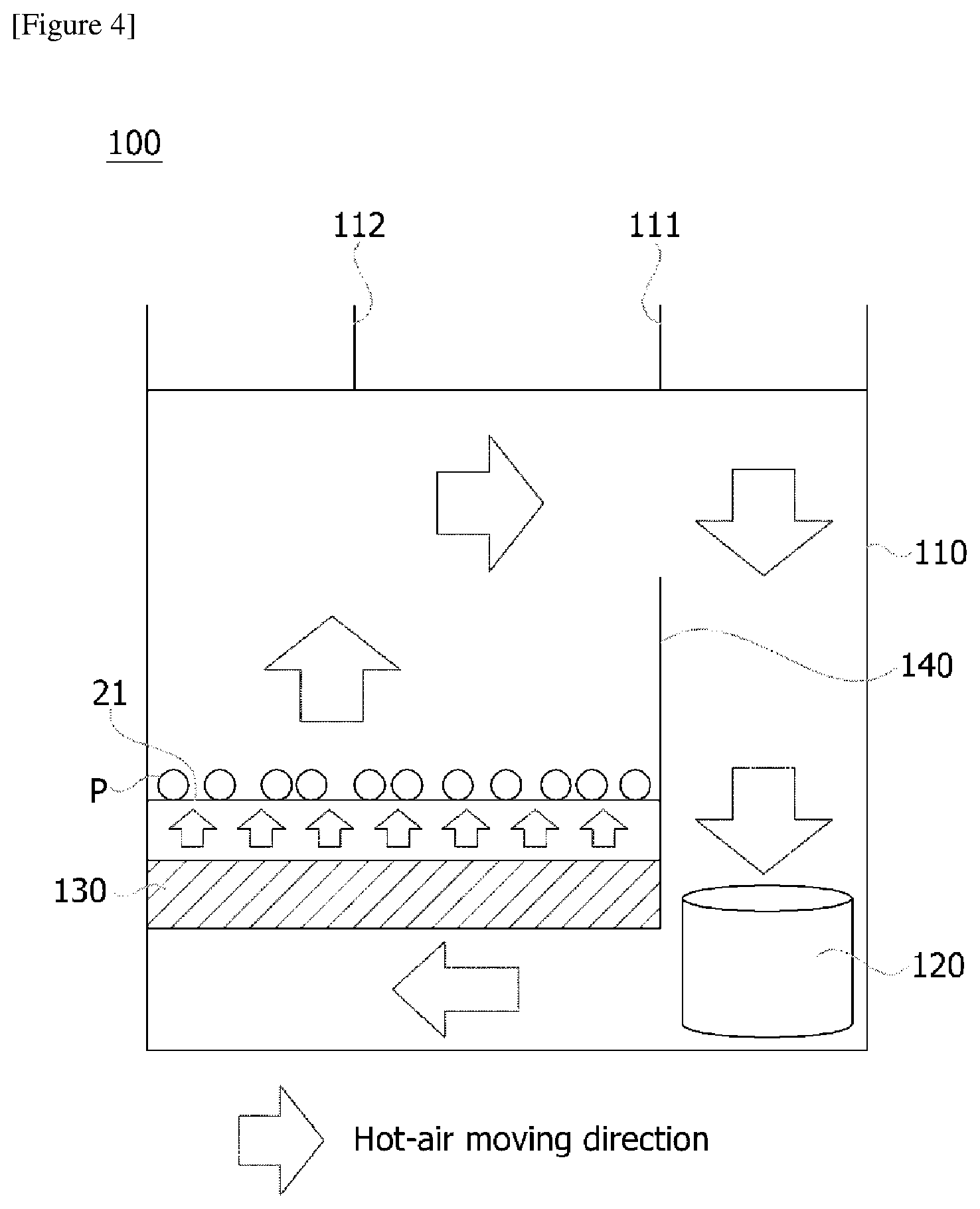
[0034] Referring to FIG. 4, the heating part (100) comprises a drying chamber (110) for providing a drying space. The drying chamber (110) is provided with an inlet (111) through which external air flows and an outlet (112) through which gases and foreign substances in the drying chamber (110) are discharged to the outside, respectively.
[0035] Also, the heating part (100) comprises a heat exchanger (130) and a blast fan (120) disposed in the drying chamber (110), respectively. Here, the heating part (100) is provided so that the air discharged from the blast fan (120) is supplied to the transfer conveyor after passing through the heat exchanger (130).
[0036] Furthermore, the heat exchanger (130) is provided so that the air passing through the heat exchanger (130) can be distributed across the width direction (the x-axis direction in FIG. 2) of the transfer conveyor. The heat exchanger (130) is also disposed below the transfer conveyor. In particular, the heat exchanger (130) is elongated along the width direction so as to correspond to the width of the transfer conveyor. Through this structure, a uniform flow distribution can be formed without using a conventional distribution plate, and a wide heat transfer area can be secured.
[0037] In addition, the heating part (100) comprises a partition wall (140) for separating the inflow side and the inflow side of the blower (120). That is, the air discharged from the blower (120) is only delivered to the heat exchanger (130) side, and the hot air passing through the heat exchanger (130) is supplied only to the belt (21), by the partition wall (140).
[0038] The particle dispersing device (10) comprises a rotary member (11) provided at one side of the transfer conveyor and having a rotation center. Also, the particle dispersing device comprises a drive part (not shown) for rotating the rotary member (11) and a particle supply part (12) mounted on the rotary member (11) and having the particles stored therein. The particle dispersing device comprises a control part (not shown) for controlling the transfer conveyor and the drive part.
[0039] Furthermore, the control part controls the heating part.
[0040] On the other hand, the drive part may comprise, for example, a motor shaft-connected to the rotary member (11). As long as the particle supply part (12) can drop particles onto the transfer conveyor by vibration or the like, the type is not limited, but for example, the particle supply part (12) may comprise a belt conveyor. Thus, the particles (P) settled on the belt can be applied on the belt (21) of the transfer conveyor in accordance with the operation of the particle supply part (12). In addition, the particles can be supplied to the particle supply part (12) through a hopper (not shown) where a large amount of particles are stored, or the like.
[0041] Referring to FIG. 3, when the particles are supplied to the transfer conveyor, the control part controls so that the particle supply part (12) is rotated with drawing an arc on the basis of the rotation center of the rotary member (11) in a predetermined direction (clockwise and/or counterclockwise).
[0042] The control part stops the transfer conveyor when the particle supply part (12) is rotated. Also, when the rotation of the particle supply part is completed, the control part operates the transfer conveyor such that the loaded particles are transported. A symbol MD denotes the conveying direction of the transfer conveyor. In addition, a reference numeral 21 denotes a belt of the transfer conveyor on which the particles are loaded.
[0043] Also, the control part controls so that the particle supply part (12) rotationally reciprocates in different directions (clockwise and counterclockwise) within a predetermined angular range on the basis of the rotation center. For example, the control part controls so that the particle supply part (12) rotates clockwise on the basis of the rotation center, and then controls so that the particle supply part (12) rotates counterclockwise on the basis of the rotation center. That is, when the reciprocating rotational movement is completed once, the particle supply part (12) returns to the initial position.
[0044] Furthermore, the particle supply part (12) may be positioned at the edge of the transfer conveyor (20) in the width direction after the rotation in one direction is completed. In addition, the width direction indicates a direction orthogonal to the conveying direction (MD).
[0045] Specifically, the control part stops the transfer conveyor upon rotating the particle supply part (12) in a first direction (clockwise direction). Also, when the rotation of the particle supply part (12) in the first direction is completed, the control part operates the transfer conveyor such that the loaded particles are transported.
[0046] Thereafter, the control part stops the transfer conveyor again upon rotating the particle supply part (12) in a second direction (counterclockwise direction) opposite to the first direction. Furthermore, when the rotation of the particle supply part (12) in the second direction is completed, the control part again operates the transfer conveyor (20) such that the loaded particles are transported.
[0047] In addition, the control part can control so that along the width direction of the transfer conveyor, the particles are loaded thicker on both side edges than the center portion. That is, when the particles are loaded on the transfer conveyor in the manner as above, the thickness of the particles loaded on both side edges along the width direction of the transfer conveyor may increase, but it has an effect capable of preventing lifting by strong hot air from the heating part.
[0048] The preferred examples of the present invention as described above are disclosed for illustrative purposes, which can be modified, changed and added within thought and scope of the present invention by those skilled in the art and it will be considered that such modification, change and addition fall within the following claims.
[0049] The drying system according to the present invention can uniformly disperse the particles on the transfer conveyor and can form a uniform flow distribution across the width direction of the transfer conveyor with a wide heat transfer area.
* * * * *
D00000
D00001
D00002
D00003
XML
uspto.report is an independent third-party trademark research tool that is not affiliated, endorsed, or sponsored by the United States Patent and Trademark Office (USPTO) or any other governmental organization. The information provided by uspto.report is based on publicly available data at the time of writing and is intended for informational purposes only.
While we strive to provide accurate and up-to-date information, we do not guarantee the accuracy, completeness, reliability, or suitability of the information displayed on this site. The use of this site is at your own risk. Any reliance you place on such information is therefore strictly at your own risk.
All official trademark data, including owner information, should be verified by visiting the official USPTO website at www.uspto.gov. This site is not intended to replace professional legal advice and should not be used as a substitute for consulting with a legal professional who is knowledgeable about trademark law.