Logging Device For Measuring Pressure Into An Underground Formation And Associated Method
VENTRE; Pierre
U.S. patent application number 16/627143 was filed with the patent office on 2020-05-07 for logging device for measuring pressure into an underground formation and associated method. This patent application is currently assigned to TOTAL SA. The applicant listed for this patent is TOTAL SA. Invention is credited to Pierre VENTRE.
| Application Number | 20200141234 16/627143 |
| Document ID | / |
| Family ID | 59745312 |
| Filed Date | 2020-05-07 |

| United States Patent Application | 20200141234 |
| Kind Code | A1 |
| VENTRE; Pierre | May 7, 2020 |
LOGGING DEVICE FOR MEASURING PRESSURE INTO AN UNDERGROUND FORMATION AND ASSOCIATED METHOD
Abstract
The invention relates to a logging device for measuring pressure into an underground formation, comprising at least one formation pressure sensor which comprises a tool body part and a probe mounted on the tool body part, said probe comprising a fluid withdrawal line. The tool body part comprises a flow line connected to the fluid withdrawal line, at least one test chamber connected to the flow line and an at least one respective closing system, and at least one pressure sensor connected to the flow line. The probe further comprises a rupture chamber and a pressure sensor connected to the fluid withdrawal line and, a first isolating valve on the fluid withdrawal line downstream of the rupture chamber and upstream to the flow line adapted to isolate the rupture chamber from the flow line when the rupture chamber is actuated.
| Inventors: | VENTRE; Pierre; (PAU Cedex, FR) | ||||||||||
| Applicant: |
|
||||||||||
|---|---|---|---|---|---|---|---|---|---|---|---|
| Assignee: | TOTAL SA COURBEVOIE FR |
||||||||||
| Family ID: | 59745312 | ||||||||||
| Appl. No.: | 16/627143 | ||||||||||
| Filed: | June 27, 2017 | ||||||||||
| PCT Filed: | June 27, 2017 | ||||||||||
| PCT NO: | PCT/IB2017/000974 | ||||||||||
| 371 Date: | December 27, 2019 |
| Current U.S. Class: | 1/1 |
| Current CPC Class: | E21B 47/06 20130101; E21B 49/081 20130101; E21B 49/082 20130101; E21B 47/024 20130101; E21B 49/10 20130101; E21B 49/00 20130101; E21B 49/083 20130101 |
| International Class: | E21B 49/10 20060101 E21B049/10; E21B 47/06 20060101 E21B047/06; E21B 49/08 20060101 E21B049/08; E21B 49/00 20060101 E21B049/00; E21B 47/024 20060101 E21B047/024 |
Claims
1. A logging device for measuring pressure into an underground formation containing a fluid, said logging device comprising: at least one formation pressure sensor, said formation pressure sensor comprising a tool body part and a probe mounted on the tool body part, said probe comprising a fluid withdrawal line intended to be placed in fluid communication with the underground formation after rupture of a mud cake, the tool body part comprising a flow line connected to the fluid withdrawal line, several parallel test chambers connected to the flow line and several respective closing systems adapted to fluidly isolate each test chamber from the flow line, and at least one pressure sensor connected to the flow line, wherein the probe further comprises a rupture chamber intended to be actuated to rupture the mud cake by suction and a pressure sensor connected to the fluid withdrawal line and, a first isolating valve on the fluid withdrawal line downstream of the rupture chamber and upstream to the flow line adapted to isolate the rupture chamber from the flow line when the rupture chamber is actuated.
2. The logging device according to claim 1, wherein the probe further comprises a second isolating valve different from the first isolating valve between the rupture chamber and the fluid withdrawal line adapted to isolate the rupture chamber from the fluid withdrawal line when at least one of test chambers is actuated, or wherein the first isolating valve is a three-way valve connected to the fluid withdrawal line adapted to isolate the rupture chamber from the fluid withdrawal line when at least one of the test chambers is actuated.
3. The logging device according to claim 2, further comprising a control unit adapted to actuate the rupture chamber, the first isolating valve and the second isolating valve, at least one of the closing systems and at least one of the test chambers between a first mud cake rupturing configuration wherein the first isolating valve is closed, the second isolating valve is opened and the rupture chamber is actuated and a second configuration wherein the first isolating valve is opened, the second isolating valve is closed, at least one of the closing systems are opened and at least one of the test chambers is actuated, or wherein the logging device further comprises a control unit adapted to actuate the rupture chamber, the three-way valve, at least one of the closing system and at least one of the test chambers between a first mud cake rupturing configuration wherein the three-way valve allows only the fluid circulation between the rupture chamber and the first end of the fluid withdrawal line and the rupture chamber is actuated, and a second configuration wherein the three-way valve allows only the fluid circulation between the first end of the fluid withdrawal line and the flow line, at least one of the closing systems is opened and at least one of the test chambers is actuated.
4. The logging device according to claim 1, wherein the volume of each of the test chambers is more than the volume of the rupture chamber.
5. The logging device according to claim 1, wherein the rupture chamber defines a cavity and comprises a piston movable into the cavity between a retracted position and an extended position.
6. The logging device according to claim 1, further comprising a plurality of different sensors and a processing unit, said sensors being configured to provide measurements to the processing unit, said processing unit being configured to process said measurements to determine at least a value of a physical parameter of the environment of the logging device and at least a redundant value of the same physical parameter of the environment of the logging device, the value and the redundant value being determined from at least two different sensors measurements measuring different physical parameters.
7. The logging device according to claim 6, wherein the plurality of different sensors are chosen among a plurality of formation pressure sensors at different heights, a plurality of hydrostatic well pressure sensors at different heights, a gradio-manometer sensor, a gamma-ray sensor, a cable tension sensor and/or an inclinometer sensor.
8. The logging device according to claim 6, wherein at least one first sensor of the plurality of sensors is configured to provide at least one direct measurement of a value of a physical parameter of the environment of the logging device to the processing unit and the processing unit is configured to calculate at least one redundant value of the same physical parameter through the measurements of at least a second sensor among the plurality of sensors, the second sensor measuring a physical parameter of the environment of the logging device different from the physical parameter of the environment of the logging device measured by the first sensor.
9. The logging device according to claim 6, further comprising a computation unit configured to calculate an uncertainty and/or a coherence of the at least one physical parameter of the environment of the logging device, based on the at least one value of the physical parameter and on the at least one redundant value of the same physical parameter obtained from the at least two different sensors.
10. The logging device according to claim 6, further comprising a communication unit configured to communicate the uncertainty and/or the coherence of the at least one physical parameter to an operator.
11. The logging device according to claim 6, further comprising an automatic control unit configured to control at least one of the test chambers and/or the rupture chamber, said automatic controlling unit being connected to the computation unit and/or to the processing unit in order to adjust the parameters of fluid suction of at least one of the test chambers and/or the parameters of the rupture chamber based on the measurements of at least one sensor, on the at least one value and the at least one redundant value of at least one physical parameter and/or based on an uncertainty and/or a coherence of the physical parameter obtained from the at least two different sensors.
12. A method for measuring pressure into an underground formation containing a fluid using a logging device according to claim 1, comprising the following steps: putting the probe in contact with a mud cake of the underground formation, closing the first isolating valve, actuating the rupture chamber so as to establish fluid communication between the underground formation and the fluid withdrawal line by rupturing the mud cake, opening the first isolating valve, actuating at least one of the test chambers so as to suction fluid inside the at least one of the test chambers, ensuring fluid isolation of the at least one of the test chambers from the flow line by closing the respective at least one of the closing systems of the at least one of the test chambers, measuring the pressure stabilization in the flow line.
13. The method according to claim 12, further comprising a step of closing a second isolating valve different from the first isolating valve between the rupture chamber and the fluid withdrawal line, to isolate the rupture chamber from the fluid withdrawal line before opening the first isolating valve, or wherein the first isolating valve is a three-way valve connected to the fluid withdrawal line, the method comprising a step of actuating the three-way valve to isolate the rupture chamber from the fluid withdrawal line before actuating the at least one of the test chambers.
14. The method according to claim 12, further comprising a step of acquiring measurements with a plurality of sensors and processing said measurements to determine at least a value of a physical parameter of the environment of the logging device and at least a redundant value of the same physical parameter of the environment of the logging device, the value and the redundant value being determined from at least two different sensors measurements measuring different physical parameters.
15. The method according to claim 14, further comprising a step of computing an uncertainty and/or a coherence of the at least one physical parameter by the calculation unit based on the at least one value of the physical parameter and on the at least one redundant value of the physical parameter obtained from the at least two different sensors.
16. The method according to claim 15, further comprising a step of communicating the uncertainty and/or the coherence of the at least one physical parameter to an operator by the communication unit.
17. The method according to claim 14, further comprising a step of automatic controlling of the at least one of the test chambers and/or the rupture chamber so as to adjust the parameters of fluid suction of the at least one of the test chambers and/or the parameters of the rupture chamber based on the measurements of the at least one sensor, based on the at least one value and the at least one redundant value of at least one physical parameter and/or based on an uncertainty and/or a coherence of the physical parameter obtained from the at least two different sensors.
Description
CROSS REFERENCE TO RELATED APPLICATIONS
[0001] This is a U.S. National Phase Application under 35 U.S.C. .sctn. 371 of International Patent Application No. PCT/IB2017/000974, filed Jun. 27, 2017. The entire contents of which are hereby incorporated by reference.
FIELD OF THE INVENTION
[0002] The present invention concerns a logging device for measuring pressure into an underground formation containing a fluid, said logging device comprising at least one formation pressure sensor, said formation pressure sensor comprising a tool body part and a probe mounted on the tool body part, said probe comprising a fluid withdrawal line intended to be placed in fluid communication with the underground formation after rupture of a mud cake, the tool body part comprising a flow line connected to the fluid withdrawal line, at least one test chamber connected to the flow line and at least one respective closing system adapted to fluidly isolate the at least one test chamber from the flow line, and at least one pressure sensor connected to the flow line.
BACKGROUND
[0003] This logging device is for example lowered in wells for oil and gas exploration, for mining exploration or for aquifer hydrological studies so as to determine punctually at various measurement stations along the depth of the well, the formation pressure. Formation pressure typically gives information concerning the mobility of the fluids contained in the underground formation and the permeability of said underground formation.
[0004] Classically, the pressure of the underground formation is measured by locally imposing a vacuum on the wall of the well, through fluid suction in the test chamber after the rupture of the mud cake. The test chamber is then in fluid communication with the underground formation and a predetermined volume of fluid is sucked at a predetermined flow rate by the test chamber. This creates a pressure drop in the flowline. This step is referred as the drawdown. The drawdown continues with pressure dropping as the volume of fluid is sucked by the test chamber. When the test chamber stops sucking the fluid, the pressure starts to build-up. Given a sufficient amount of time, the pressure in the flow line reaches equilibrium with the formation pressure. The time evolution of the pressure during the drawdown and during the build-up is interpreted for example in terms of permeability of the underground formation.
[0005] The main drawback of the current devices is that the underground formation and the flow line of the logging device are sometimes in poor fluid communication due to a partial rupture of the mud cake, leading to inconsistent measurements of formation pressure. Moreover, the tool capacity is not minimized in existing devices. The pressure build up is then slower, which leads to an uncertainty in the estimation of the formation pressure.
[0006] On the contrary, when the mud cake is partially porous, its permeability may interfere with the permeability of the formation leading to an over estimation of the pressure called "supercharging".
SUMMARY
[0007] One aim of the invention is to increase the reliability and the relevance of the measurements of formation pressure in the underground formation.
[0008] To this end, the subject-matter of the invention is a logging device of the aforementioned type, characterized in that the probe further comprises a rupture chamber intended to be actuated to rupture the mud cake by suction and a pressure sensor connected to the fluid withdrawal line and, a first isolating valve on the fluid withdrawal line downstream of the rupture chamber and upstream to the flow line adapted to isolate the rupture chamber from the flow line when the rupture chamber is actuated.
[0009] According to various embodiments, the logging device according to the invention comprises one or more of the following features, taken into consideration in isolation, or in accordance with any technically possible combination: [0010] the probe further comprises a second isolating valve different from the first isolating valve between the rupture chamber and the fluid withdrawal line adapted to isolate the rupture chamber from the fluid withdrawal line when the at least one test chamber is actuated, or wherein the first isolating valve is a three-way valve connected to the fluid withdrawal line adapted to isolate the rupture chamber from the fluid withdrawal line when the at least one test chamber is actuated; [0011] the logging device further comprises a control unit adapted to actuate the rupture chamber, the first isolating valve and the second isolating valve, the at least one closing system and the at least one test chamber between a first mud cake rupturing configuration wherein the first isolating valve is closed, the second isolating valve is opened and the rupture chamber is actuated and a second configuration wherein the first isolating valve is opened, the second isolating valve is closed, the at least one closing system are opened and the at least one test chamber is actuated, or wherein the logging device further comprises a control unit adapted to actuate the rupture chamber, the three-way valve, the at least one closing system and the at least one test chamber between a first mud cake rupturing configuration wherein the three-way valve allows only the fluid circulation between the rupture chamber and the first end of the fluid withdrawal line and the rupture chamber is actuated, and a second configuration wherein the three-way valve allows only the fluid circulation between the first end of the fluid withdrawal line and the flow line, the at least one closing system are opened and the at least one test chamber is actuated; [0012] the volume of the at least one test chamber is more than the volume of the rupture chamber; [0013] the rupture chamber defines a cavity and comprises a piston movable into the cavity between a retracted position and an extended position; [0014] the logging device further comprises a plurality of different sensors and a processing unit, said sensors being configured to provide measurements to the processing unit, said processing unit being configured to process said measurements to determine at least a value of a physical parameter of the environment of the logging device and at least a redundant value of the same physical parameter of the environment of the logging device, the value and the redundant value being determined from at least two different sensors measurements measuring different physical parameters; [0015] the plurality of different sensors are chosen among a plurality of formation pressure sensors at different heights, a plurality of hydrostatic well pressure sensors at different heights, a gradio-manometer sensor, a gamma-ray sensor, a cable tension sensor and/or an inclinometer sensor; [0016] at least one first sensor of the plurality of sensors is configured to provide at least one direct measurement of a value of a physical parameter of the environment of the logging device to the processing unit and the processing unit is configured to calculate at least one redundant value of the same physical parameter through the measurements of at least a second sensor among the plurality of sensors, the second sensor measuring a physical parameter of the environment of the logging device different from the physical parameter of the environment of the logging device measured by the first sensor; [0017] the logging device further comprises a computation unit configured to calculate an uncertainty and/or a coherence of the at least one physical parameter of the environment of the logging device, based on the at least one value of the physical parameter and on the at least one redundant value of the same physical parameter obtained from the at least two different sensors; [0018] the logging device further comprises a communication unit configured to communicate the uncertainty and/or the coherence of the at least one physical parameter to an operator; [0019] the logging device further comprises an automatic control unit configured to control the at least one test chamber and/or the rupture chamber, said automatic controlling unit being connected to the computation unit and/or to the processing unit in order to adjust the parameters of fluid suction of the at least one test chamber and/or the parameters of the rupture chamber based on the measurements of at least one sensor, on the at least one value and the at least one redundant value of at least one physical parameter and/or based on an uncertainty and/or a coherence of the physical parameter obtained from the at least two different sensors.
[0020] The subject-matter of the invention also relates to a method for measuring pressure into an underground formation containing a fluid using a logging device as described above, comprising the following steps: [0021] putting the probe in contact with a mud cake of the underground formation, [0022] closing the first isolating valve, [0023] actuating the rupture chamber so as to establish fluid communication between the underground formation and the fluid withdrawal line by rupturing the mud cake, [0024] opening the first isolating valve, [0025] actuating the at least one test chamber so as to suction fluid inside the at least one test chamber, [0026] ensuring fluid isolation of the at least one test chamber from the flow line by closing the respective at least one closing system of the at least one test chamber, [0027] measuring the pressure stabilization in the flow line.
[0028] According to various embodiments, the method according to the invention includes one or more of the following features: [0029] the method further comprises a step of closing a second isolating valve different from the first isolating valve between the rupture chamber and the fluid withdrawal line, to isolate the rupture chamber from the fluid withdrawal line before opening the first isolating valve, or wherein the first isolating valve is a three-way valve connected to the fluid withdrawal line, the method comprising a step of actuating the three-way valve to isolate the rupture chamber from the fluid withdrawal line before actuating the at least one test chamber; [0030] the method further comprises a step of acquiring measurements with a plurality of sensors and processing said measurements to determine at least a value of a physical parameter of the environment of the logging device and at least a redundant value of the same physical parameter of the environment of the logging device, the value and the redundant value being determined from at least two different sensors measurements measuring different physical parameters; [0031] the method further comprises a step of computing an uncertainty and/or a coherence of the at least one physical parameter by the calculation unit based on the at least one value of the physical parameter and on the at least one redundant value of the physical parameter obtained from the at least two different sensors; [0032] the method further comprises a step of communicating the uncertainty and/or the coherence of the at least one physical parameter to an operator by the communication unit; [0033] the method further comprises a step of automatic controlling of the at least one test chamber and/or the rupture chamber so as to adjust the parameters of fluid suction of the at least one test chamber and/or the parameters of the rupture chamber based on the measurements of the at least one sensor, based on the at least one value and the at least one redundant value of at least one physical parameter and/or based on an uncertainty and/or a coherence of the physical parameter obtained from the at least two different sensors.
[0034] The invention also concerns a logging device for measuring pressure into an underground formation containing a fluid, said logging device comprising at least one formation pressure sensor, said formation pressure sensor comprising a tool body part and a probe mounted on the tool body part, said probe comprising a fluid withdrawal line intended to be placed in fluid communication with the underground formation after rupture of a mud cake, the tool body part comprising a flow line connected to the fluid withdrawal line, at least one test chamber connected to the flow line and an at least one respective closing system adapted to fluidly isolate the test chamber from the flow line, and at least one pressure sensor connected to the flow line.
[0035] The logging device further comprises a plurality of different sensors and a processing unit, said sensors being configured to provide measurements to the processing unit, said processing unit being configured to process said measurements to determine at least a value of a physical parameter of an environment of the logging device and at least a redundant value of the same physical parameter of the environment of the device, the value and the redundant value being determined from at least two different sensors measurements measuring different physical parameters.
[0036] The logging device according to the invention may or may not comprise the feature by which the probe further comprises a rupture chamber intended to be actuated to rupture the mud cake by suction and a pressure sensor connected to the fluid withdrawal line and, a first isolating valve on the fluid withdrawal line downstream of the rupture chamber and upstream to the flow line adapted to isolate the rupture chamber from the flow line when the rupture chamber is actuated.
[0037] The logging device according to the invention comprises one or more of the above features, taken into consideration in isolation, or in accordance with any technically possible combination.
BRIEF DESCRIPTION OF THE DRAWINGS
[0038] The invention will be better understood upon reading of the following description, taken solely as an example, and made in reference to the following drawings, in which:
[0039] FIG. 1 is a schematic view of the logging device according to the invention inside a sub-vertical well,
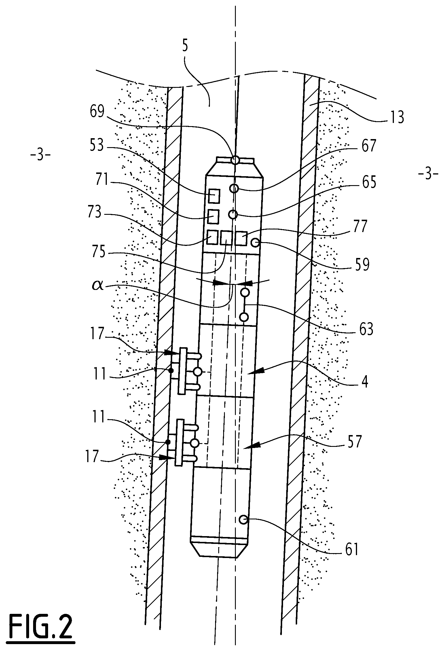
[0040] FIG. 2 is a schematic view of the logging device of FIG. 1 inside an at least locally inclined portion of a well,
[0041] FIG. 3 is a partial schematic representation of the logging device of FIG. 1 illustrating a probe of the logging device,
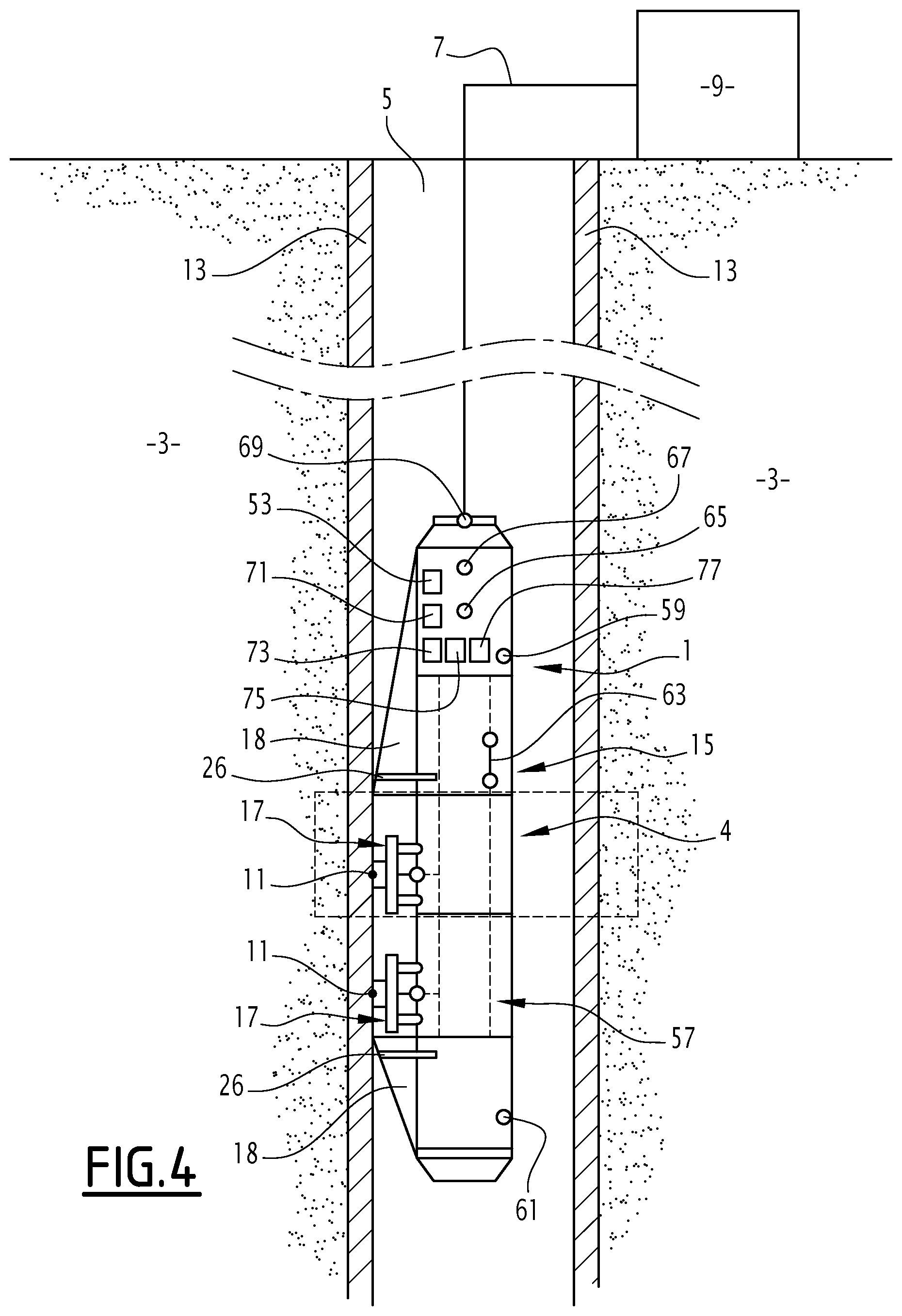
[0042] FIGS. 4 and 5 are schematic representations of a variant of the logging device of FIG. 1 comprising deflectors and a bow-spring,
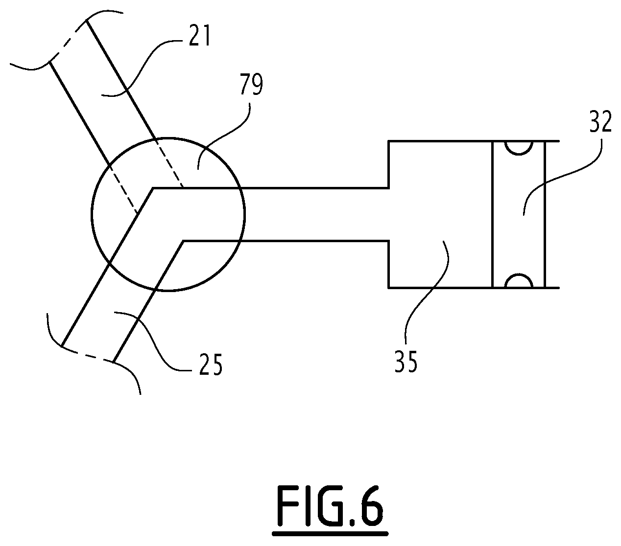
[0043] FIG. 6 is a schematic representation of a three-way valve used in variant of the first and the second isolating valves.
DETAILED DESCRIPTION
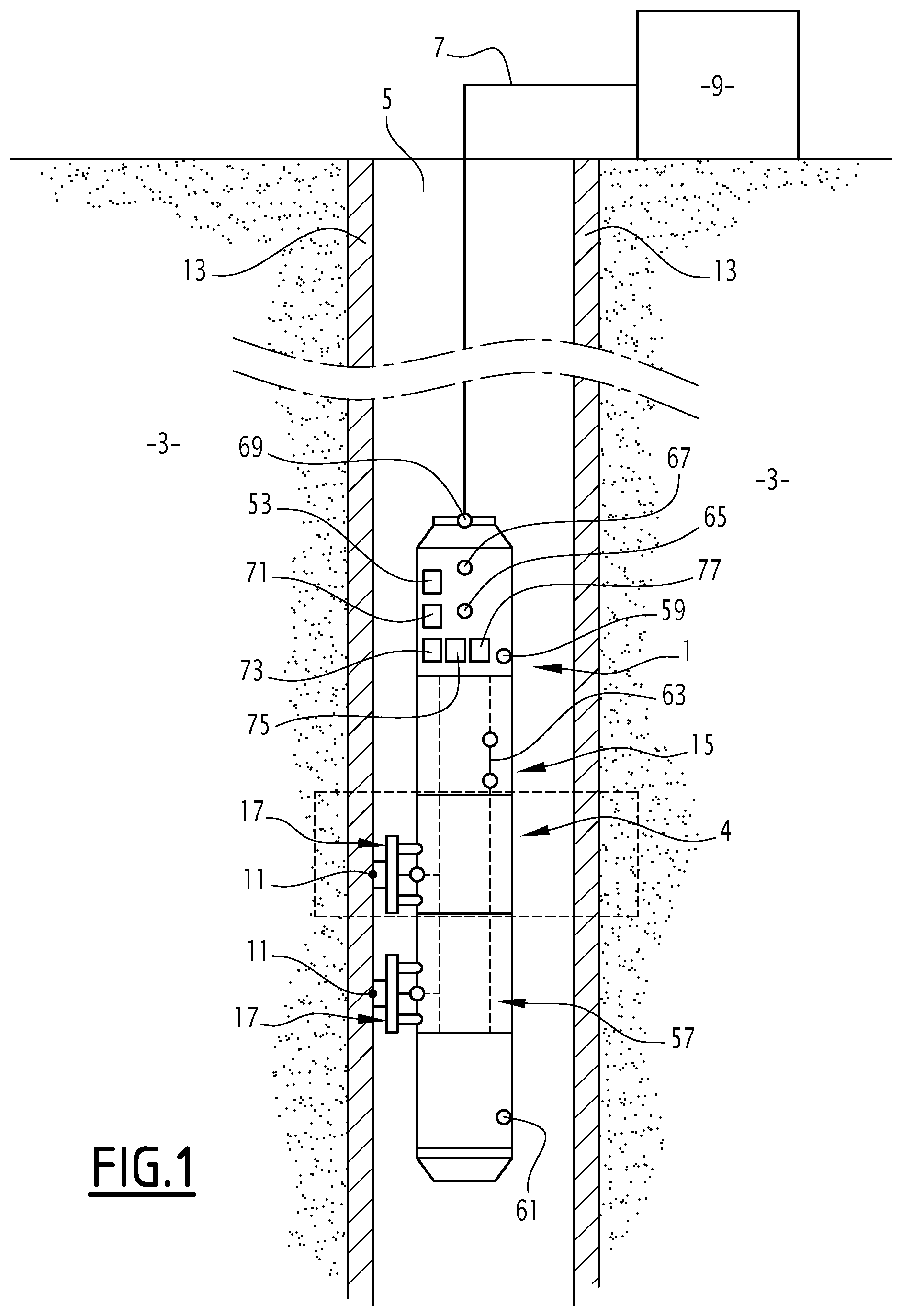
[0044] A logging device 1 for measuring pressure into an underground formation 3 according to the invention is shown in FIG. 1 and FIG. 2. The logging device 1 is adapted to be lowered in a well 5 drilled in the underground formation 3 containing a fluid. The term "fluid" refers to gas, liquid or a mix of gas and liquid. For example, in oil exploration, the fluid in the underground formation 3 generally comprises a mix of water, oil and gas.
[0045] The well 5 is for example an exploration, a production or an injection well for oil and gas or mining exploration or a well performed for aquifer characterization studies.
[0046] The well 5 is here represented vertical. The well 5 may also comprise inclined or even horizontal portions.
[0047] Typically, the logging device 1 comprises a downhole formation pressure sensor 4 and a line 7 adapted to lower the logging device 1 into the well 5. The line 7 is connected on the surface to a hoisting system 9 adapted to lower or to raise the logging device 1. For example, the hoisting system 9 is an electrical winch. Moreover, the line 7 is an electric wireline generally adapted to transmit the data measured by the logging device to a data recording unit (not represented) located on the surface, or a slickline.
[0048] The logging device 1 is lowered in the well 5 and stopped at predetermined depths called measurement stations 11 where the measurements are performed.
[0049] During the drilling of the well 5, the well 5 is filled with a drilling fluid such as water-based or oil-based fluid. The density of the drilling fluid is for example increased by adding solids, such as salts and other additives, to form a drilling mud. The drilling mud makes it possible to obtain a hydrostatic pressure in the well 5 adapted to avoid the cave-in of the well 5 and prevent the fluid of the underground formation 3 from escaping into the well 5.
[0050] The drilling mud forms a layer on the inner wall of the well, called mud cake 13. The mud cake 13 isolates the underground formation 3 from the inside of the well 5.
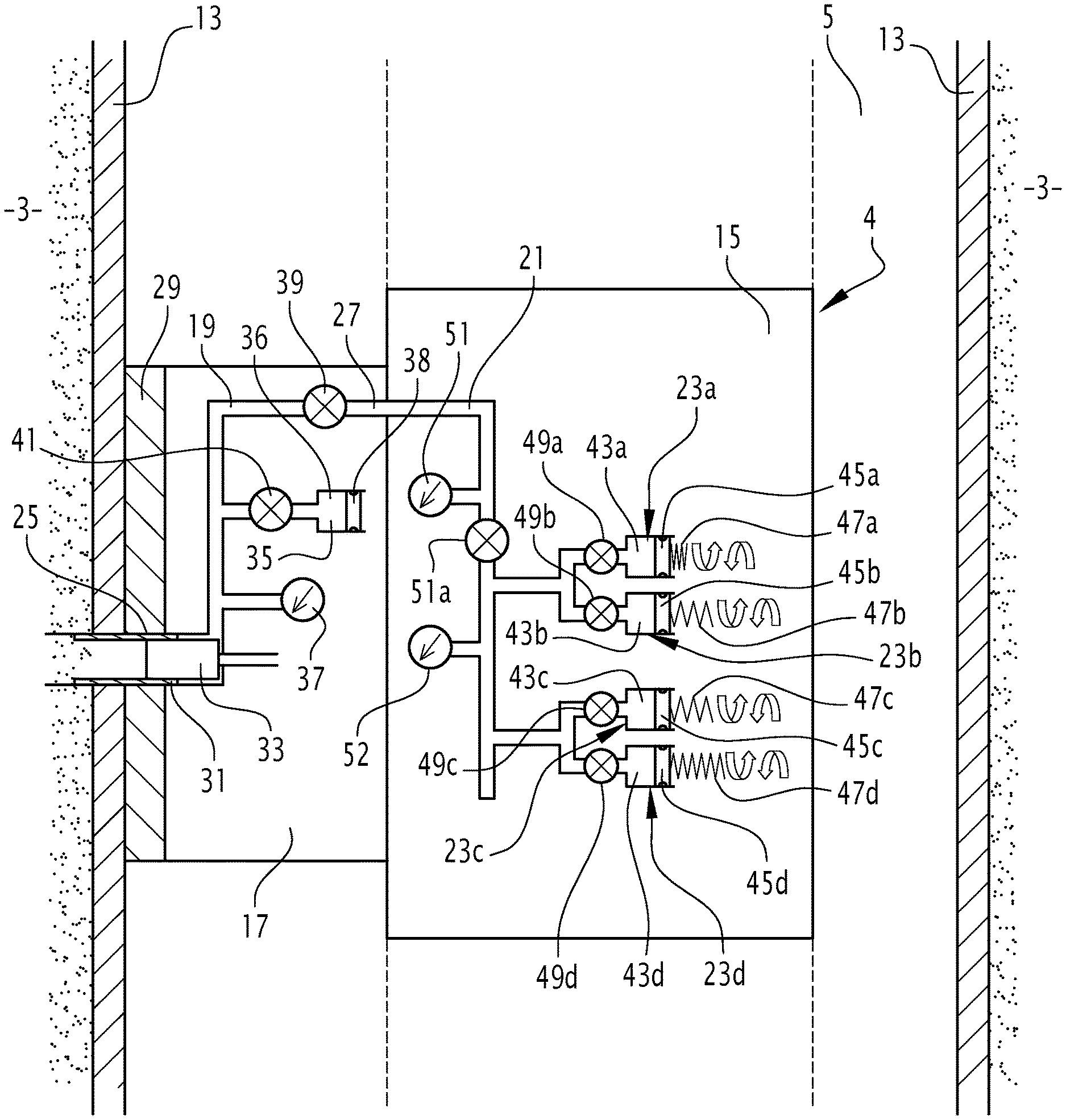
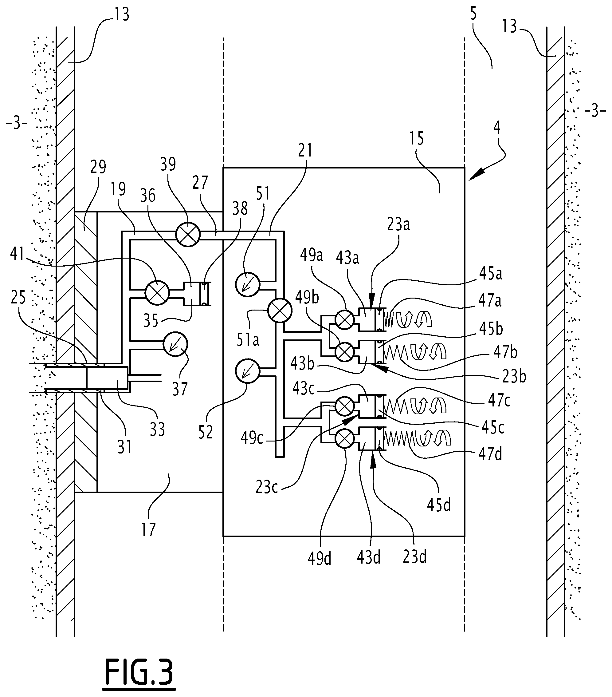
[0051] As schematically visible on FIG. 3, the first formation pressure sensor 4 comprises a tool body part 15 and a probe 17 mounted on the tool body part 15 to connect to the formation.
[0052] The probe 17 comprises a fluid withdrawal line 19. The tool body part 15 extends along a longitudinal axis. It comprises a flow line 21 connected to the fluid withdrawal line 19 and at least one test chamber 23a, 23b, 23c, 23d.
[0053] The probe 17 is for example transversely extendable from the tool body part 15 for sealing engagement with the wall of well 5. Typically, the probe 17 transversely protrudes from the tool body part 15 toward the wall of the well 5 and is anchored to the wall of the well 5 at each measurement station 11.
[0054] For example, the extension of the probe 17 from the tool body part 15 is carried out using hydraulic, mechanical and/or electrical means or a combination thereof.
[0055] In reference to FIG. 3, the fluid withdrawal line 19 comprises a first end 25 intended to be placed in fluid communication with the underground formation 3 after the rupture of the mud cake 13. The fluid withdrawal line 19 comprises a second end 27 intended to be connected to the flow line 21 of the tool body part 15.
[0056] Typically, the probe 17 further comprises a packer 29 disposed around the first end 25 of the fluid withdrawal line 19.
[0057] The packer 29 is for example made with an elastomeric material.
[0058] In a variant, the packer 29 consists in an inflatable element.
[0059] According to another embodiment, the packer 29 consists in a set of upper and lower inflatable elements respectively disposed onto an upper portion and onto a lower portion of well, respectively above and below the first end 25 of the fluid withdrawal line 19.
[0060] At each measurement station 11, prior to the rupture of the mud cake 13, the upper and lower inflatable elements are inflated so as to exert a pressure onto the upper portion and the lower portion of the well 5.
[0061] The packer 29 seals against the wall of the well 5 to fluidly isolate a portion of the wall 5. The packer 29 allows improving the effectiveness of formation pressure measurements.
[0062] The probe 17 further comprises at least one filter 31 adapted to filter the particles contained in the fluid of the underground formation 3. For example, the filter 31 consists in a strainer in stainless steel disposed on a portion of the first end 25 of the fluid withdrawal line 19.
[0063] The probe 17 further comprises a filter piston 33 movable into the first end 25 of the fluid withdrawal line 19 between an extended position towards the underground formation 3 and a retracted position away from the underground formation 3.
[0064] Typically, the filter piston 33 is adapted to clean the filter 31 from the particles disposed on the filter 31.
[0065] For example, the filter piston 33 is actuated before each formation pressure measurement.
[0066] According to the invention, the probe 17 comprises a rupture chamber 35 intended to be actuated to rupture the mud cake 13 by suction. The rupture chamber 35 is for example a low pressure chamber.
[0067] Typically, the rupture chamber 35 defines a cavity 36 and comprises a piston 38 movable into the cavity 36 between a retracted position and an extended position.
[0068] Typically, the suction pressure provided in the rupture chamber 35 is linked to the mud cake rupture pressure which may vary from one measurement station to another one. It does not exceed a limited drawdown pressure chosen to preserve the packer 29 integrity (linked to the mechanical resistance of the packer 29).
[0069] In a preferred embodiment, the volume of each test chamber 23a, 23b, 23c, 23d is more than the volume of the rupture chamber 35. The volume of the rupture chamber 35 is typically comprised between 1 cc and 5 cc, for example 3 cc. Typically, the volume of the rupture chamber 35 is linked to the above-mentioned exerted suction pressure and the internal fluid compressibility.
[0070] Typically, the probe 17 further comprises a pressure sensor 37 tapped on the fluid withdrawal line 19 intended to measure the pressure in the fluid withdrawal line 19 when said fluid withdrawal line 19 is in fluid communication with the underground formation 3.
[0071] The probe 17 also comprises a first isolating valve 39 on the fluid withdrawal line 19 downstream of the rupture chamber 35 and upstream to the flow line 21 adapted to isolate the rupture chamber 35 from the flow line 21 when the rupture chamber 35 is actuated.
[0072] The terms "downstream" and "upstream" are defined relatively to a movement of the fluid from the underground formation to the test chamber 23a, 23b, 23c, 23d.
[0073] Advantageously, the probe 17 further comprises a second isolating valve 41 between the rupture chamber 35 and the fluid withdrawal line 19, adapted to isolate the rupture chamber 35 from the fluid withdrawal line 19.
[0074] Preferably, the tool body part 15 comprises several parallel test chambers 23a, 23b, 23c 23d which are each tapped on the flow line 21. For example, the tool body part 15 comprises between 2 to 8 test chambers 23a, 23b, 23c, 23d, preferentially between 2 to 6, typically 4 test chambers 23a, 23b, 23c, 23d as shown on FIG. 3.
[0075] Each test chamber 23a, 23b, 23c, 23d defines a test chamber cavity 43a, 43b, 43c, 43d. Each test chamber cavity 43a, 43b, 43c, 43d comprises a piston 45a, 45b, 45c, 45d adapted to move in the test chamber cavity 43a, 43b, 43c, 43d so as to cause a flow of fluid from the underground formation 3 into the test chamber cavity 43a, 43b, 43c, 43d. Typically, the flow rate inside the test chamber 23a, 23b, 23c, 23d is comprised between 0.1 cc/minute and 1000 cc/minute, preferentially between 0.1 cc/minute and 5 cc/minute.
[0076] Preferably, the pistons 45a, 45b, 45c, 45d are actuated by respective electric motors connected to worm screws 47a, 47b, 47c, 47d. The electric motors allow controlling the rate of the fluid flow inside the test chamber 23a, 23b, 23c, 23d.
[0077] Advantageously, the worm screws 47a, 47b, 47c, 47d have different screw pitches depending on the test chambers 23a, 23b, 23c, 23d. Consequently, the flow rate of each test chamber 23a, 23b, 23c, 23d is different from one test chamber 23a, 23b, 23c, 23d to another one.
[0078] The test chambers 23a, 23b, 23c, 23d have typically different volumes according to the corresponding flow rates. Typically, the volume of the test chamber 23a, 23b, 23c, 23d is comprised between 1 cc and 1000 cc, for example 300 cc.
[0079] Typically, each test chamber 23a, 23b, 23c, 23d comprises a respective closing system 49a, 49b, 49c, 49d adapted to fluidly isolate the test chamber 23a, 23b, 23c, 23d from the flow line 21. The closing system 49a, 49b, 49c, 49d is for example a valve similar to the first isolating valve 39 and the second isolating valve 41.
[0080] The tool body part 15 further comprises at least one pressure sensor 51 connected to the flow line 19 intended to measure the pressure in the flow line 19 and a fluid insulation valve 51a interposed between the pressure sensor 51 and each test chamber 23a, 23b, 23c, 23d. Then, the logging device 1 may be used with a standard non-instrumented probe of the prior art when the instrumented probe 17 described above can be removed from the tool body part 15.
[0081] Advantageously, as shown in FIG. 1 and FIG. 2, the logging device 1 comprises a control unit 53 adapted to actuate the rupture chamber 35, the first isolating valve 39 and the second isolating valve 41, the test chambers 23a, 23b, 23c, 23d, the valves 51a and 49a to 49d between a first configuration and a second configuration.
[0082] Typically, the valves 49a to 49d and the pistons 45a, 45b, 45c, 45d are controlled independently by the control unit 53.
[0083] In the first mud cake rupturing configuration, the first isolating valve 39 is closed, the second isolating valve 41 is opened and the rupture chamber 35 is actuated.
[0084] The first configuration corresponds to a first step of a measurement of formation pressure which consists in rupturing the mud cake 13 and establishing a fluid communication between the withdrawal line 19 and the underground formation 3.
[0085] In the second configuration, the first isolating valve 39 is opened, the second isolating valve 41 is closed, at least one of the test chambers 23a, 23b, 23c, 23d is actuated and the corresponding valves 49a to 49d are opened.
[0086] Typically, the second isolating valve 41 and the valves 49a to 49d are used to minimize the tool capacity during the build-up stabilization measurement.
[0087] In a variant, instead of measuring the formation pressure with the pressure sensor 51 or 52, the first isolating valve 39 is closed and the formation pressure is measured with the pressure sensor 37.
[0088] The second configuration corresponds to a second step of the test which consists in the suction of the fluid of the underground formation 3 into at least one of the test chambers 23a, 23b, 23c, 23d, once the mud cake rupture has been confirmed.
[0089] Typically, if more than one test chambers 23a, 23b, 23c, 23d are used, they are actuated successively from the test chamber having the minimal volume to the test chamber having the maximal volume.
[0090] The control unit 53 is for example intended to select which test chamber 23a, 23b, 23c, 23d to actuate and/or the sequence of actuation of the test chambers 23a, 23b, 23c, 23d and/or the flow rate of each test chamber 23a, 23b, 23c, 23d.
[0091] As seen in FIG. 1 or FIG. 2, the logging device 1 further comprises a plurality of different sensors (4, 57, 59, 61, 63, 65, 67, 69). For example, in addition to the first formation pressure sensor, the logging device further comprises a second formation pressure sensor 57 located at a different height compared to the first formation pressure sensor 4, a first hydrostatic well pressure sensor 59 and a second hydrostatic well pressure sensor 61 disposed at different heights, a gradio-manometer sensor 63, a gamma-ray sensor 65, a cable tension sensor 67 and an inclinometer sensor 69.
[0092] The first formation pressure sensor 4 and the second formation pressure sensor 57 are similar to the one described above. For example, the first formation pressure sensor 4 and the second formation pressure sensor 57 are separated by a distance D. Typically, D is comprised between 1 meter and 5 meters, for example equal to 1 meter. The first formation pressure sensor 4 and the second formation pressure sensor 57 are totally independent from one to each other. Each of the first formation pressure sensor 4 and the second formation pressure sensor 57 comprises all the elements described above. Consequently, the first formation pressure sensor 4 and the second formation pressure sensor 57 provide two independent measurements of the formation pressure of two parts of the underground formation 3 separated by the distance D. The first formation pressure sensor 4 and the second formation pressure sensor 57 are for example also adapted to measure the hydrostatic pressure caused by the column of fluid in the formation 3.
[0093] The first hydrostatic well pressure sensor 59 and the second hydrostatic well pressure sensor 61 measure directly the pressure caused by the column of fluid in the well 5. The first hydrostatic well pressure sensor 59 and the second hydrostatic well pressure sensor 61 are separated by a distance H. For example, H is comprised between 0.5 m and 1.5 m, for example 1 m. The total length of the tool may be 10 meters or more than 10 meters.
[0094] The gradiomanometer sensor 63 measures an average measurement of the fluid density inside the well 5. The gamma-ray sensor 65 measures the natural gamma-ray radiation of the underground formation 3. Generally, the gamma-ray sensor 65 is a scintillometer which comprises a crystal and at least one photomultiplier tube which converts the energy of the gamma-ray radiation in a proportional electric current. In particular, the gamma-ray radiation depends on the geological nature of the underground formation 3. Typically, the gamma-ray radiation depends on the content of natural radioelements .sup.238U, .sup.40K and .sup.232Th.
[0095] The natural gamma-ray recording is used as a readjusting tool of the depth. The tool depth is matched to a reference depth according to reference gamma-ray log acquired in the well 5 before the formation pressure measurements.
[0096] The cable tension sensor 69 measures the tension of line 7 of the logging device 1. This measurement is generally used to correct the surface displacement of the line 7 by the elongation of the line 7 taken in combination with a measurement of the line deployment obtained from the hoisting system 9.
[0097] The inclinometer 67 measures the inclination angle .alpha. (FIG. 3) between the logging device and a vertical axis.
[0098] The logging device 1 further comprises a processing unit 71 connected to the plurality of sensors. The plurality of sensors is configured to provide measurements to the processing unit 71.
[0099] The processing unit 71 is configured to process the measurements of the plurality of sensors (4, 57, 59, 61, 63, 65, 67, 69) and to determine at least a value of a physical parameter of the environment of the logging device 1 and at least a redundant value of the same physical parameter of the environment of the logging device 1, the value and the redundant value being determined from at least two different sensors measurements measuring different physical parameters.
[0100] According to one embodiment of the invention, at least one first sensor (4, 57, 59, 61, 63, 65, 67, 69) of the plurality of sensors (4, 57, 59, 61, 63, 65, 67, 69) is configured to provide at least one direct measurement of a value of a physical parameter of the environment of the logging device 1 to the processing unit 71. The processing unit 71 is configured to calculate a redundant value of the physical parameter through the measurements of at least a second sensor (4, 57, 59, 61, 63, 65, 67, 69) among the plurality of sensors (4, 57, 59, 61, 63, 65, 67, 69). The second sensor (4, 57, 59, 61, 63, 65, 67, 69) measures another physical parameter of the environment of the logging device 1 different from the physical parameter of the environment of the logging device 1 measured by the first sensor.
[0101] The other physical parameter is for example of the same physical nature as the physical parameter (for example pressures measured at different heights). Advantageously, the other physical parameter and the physical parameter are of a different physical nature (for example density and pressure).
[0102] For example, the physical parameter is the fluid density inside the well 5.
[0103] The gradiomanometer sensor 63 provides a first direct measurement p.sub.1 of the fluid density inside the well 5 to the processing unit 71.
[0104] A redundant value of the fluid density p.sub.2 inside the well 5 is calculated by the processing unit 71 using at least three other physical parameters, here the hydrostatic pressures P.sub.up and P.sub.down, respectively provided by the first hydrostatic pressure sensor 59 and by the second hydrostatic pressure sensor 61, and the inclination angle .alpha. provided by the inclination sensor 67 (see FIG. 2), according to the following equation:
p.sub.2=(P.sub.down-P.sub.up)/gHcos(.alpha.) (1)
[0105] with g being the acceleration due to gravity and H being the distance between the first hydrostatic pressure sensor 59 and the second hydrostatic pressure sensor 61.
[0106] In a variant, the physical parameter is the hydrostatic pressure determined at various heights along the logging device 1, by for example the first hydrostatic pressure sensor 59, the second hydrostatic pressure sensor 61, the first formation pressure sensor 4 and/or the second formation pressure sensor 57.
[0107] In another variant, the physical parameter is the depth of the logging device. For example a first value of the depth z.sub.1 of the logging device is determined by the processing unit by using a direct measurement of a length of the lowered line in the well corrected from an elongation of the line using the cable tension measurement provided by the cable tension sensor or the gamma-ray reference matched depth z.sub.2.
[0108] In a variant, a third value z.sub.3, a fourth value z.sub.4 and a fifth value z.sub.5 is determined by using respectively the hydrostatic pressure measured by the second hydrostatic well pressure sensor, the first formation pressure sensor and the second formation pressure sensor.
[0109] The logging device 1 further comprises a computation unit 73 configured to calculate an uncertainty and/or a coherence of the physical parameter, based on the data collected from the at least two different sensors (4, 57, 59, 61, 63, 65, 67, 69). More specifically, the calculation of the uncertainty and/or the coherence of the physical parameter is based on the values of the physical parameter and on the redundant values of the physical parameter obtained from the at least two different sensors (4, 57, 59, 61, 63, 65, 67, 69).
[0110] For example, the computation unit 73 calculates a coherence of the hydrostatic well pressures provided by the first hydrostatic pressure sensor 59, the second hydrostatic pressure sensor 61, the first formation pressure sensor 4 and/or the second formation pressure sensor 57. Typically, the variation of the measured pressure should be linear with depth.
[0111] In a variant, the computation unit 73 calculates an uncertainty and/or a coherence of the fluid density values p.sub.1 and p.sub.2, obtained as described above
[0112] Typically, the processing unit 73 is intended to determine the success or the failure of the rupture of the mud cake 13 and of the fluid communication with the underground formation 3.
[0113] For example, before the anchoring of the probe 17, the processing unit 71 is configured to compare the pressure measured by the pressure sensor connected to the fluid withdrawal line 19 with the hydrostatic pressure of the well 5 measured using the first hydrostatic well pressure sensor 59, preferably corrected from the hydrostatic pressure difference induced by the relative position of sensor 59 and probe 17 on the logging device 1. If both pressures are similar, the fluid withdrawal line 19 is not in good fluid communication with the underground formation 3 due for example to a seal failure.
[0114] Typically, the processing unit 71 is configured to monitor the time evolution of the pressure measured by the first formation pressure sensor 4 connected to the fluid withdrawal line 19. An almost time constant pressure involves a failure of the rupture of the mud cake 13.
[0115] In another variant, the computation unit calculates an uncertainty of the depth of logging device using z.sub.1, z.sub.2, z.sub.3, z.sub.4 and z.sub.5.
[0116] Advantageously, the logging device 1 comprises an automatic control unit 75 configured to control the test chambers 23a, 23b, 23c, 23d and the rupture chamber 35. The automatic control unit 75 is connected to the computation unit 73 and to the processing unit 71. For example, the automatic control unit 75 adjusts the parameters of fluid suction of the test chambers 23a, 23b, 23c, 23d, for example flow rate and/or sucked volume, and the parameter of the rupture chamber 35 based on the measurements of the sensors and on the coherence and/or the uncertainty of the redundant parameters calculated by the processing unit 71.
[0117] For example, the rupture pressure imposed by the rupture chamber 35, on the wall of the well 5 to rupture the mud cake 13 depends on the measurements of the sensors and on the uncertainty/coherence of the physical parameters.
[0118] In a variant, the rupture pressure depends on the coherence and/or uncertainty of the measurements at a previous measurement station 11.
[0119] The logging device 1 according to the invention allows automatic and real-time validation of the measurements performed in the well 5 with a minimal input of the operator.
[0120] In a variant, the logging device 1 comprises a communication unit 77 configured to communicate the uncertainty and/or the coherence of the physical parameters to an operator at the surface.
[0121] For example, the communication unit 77 informs the operator in case of a failure of a formation pressure measurement.
[0122] The operator is then able to monitor, to control and to manually adjust the parameters of the formation pressure sensor 4, 57 based on the information provided by the processing unit 71.
[0123] A method for measuring pressure into an underground formation 3 containing a fluid using a logging device 1 according to the invention will be described.
[0124] Initially, the plurality of sensors (4, 57, 59, 61, 63, 65, 67, 69) of the logging device 1 is calibrated in the surface, outside of the well 5, at normal atmospheric pressure. For example, the first formation pressure sensor 4 and the second formation pressure sensor 57 should provide an infinite permeability. The first hydrostatic well pressure sensor 59 and the second hydrostatic well pressure sensor 61 should provide the value of the atmospheric pressure.
[0125] In a next step, the plurality of sensors (4, 57, 59, 61, 63, 65, 67, 69) of the logging device 1 is calibrated in a casing. For example, the measurements of the hydrostatic well pressure are checked and calibrated. Typically, the leakage rate of the probe 17 is evaluated.
[0126] The logging device 1 is then lowered in the well 5 using the line 7. At a measurement station 11, the probe 17 of each first formation pressure sensor 4 and second formation pressure sensor 57 is put in contact with the mud cake 13 of the underground formation 3. The packer 29 is then deployed or inflated to seal the contact between the probe 17 and the mud cake 13.
[0127] For example, the first test is made using the first formation pressure sensor 4.
[0128] The first isolating valve 39 is closed so as to fluidly isolate the probe 17 from the tool body part 15 of the logging device 1.
[0129] Then, the second isolating valve 41 is opened so as to establish a fluid communication between the rupture chamber 35 and the fluid withdrawal line 19.
[0130] In a next step, the rupture chamber 35 is actuated so as to rupture the mud cake 13 and establish a fluid communication between the underground formation 3 and the fluid withdrawal line 19.
[0131] Then, the pressure in the fluid withdrawal line 19 is checked using the pressure sensor 37.
[0132] The second isolating valve 41 is then closed so as to fluidly isolate the rupture chamber 35 from the fluid withdrawal line 19.
[0133] The first isolating valve 39 is opened so as to establish a fluid communication between the flow line 21 and the fluid withdrawal line 19. The first test chamber 23a is actuated. The pressure equilibrium is typically measured with the pressure sensor 37 or the pressure sensor 51.
[0134] Measuring with the pressure sensor 37 allows decreasing the capacity effects.
[0135] For example, the first test starts by actuating the first test chamber 23a so as to suck the underground formation fluid inside the withdrawal line 19.
[0136] Typically, the first test chamber 23a is filled by the fluid up to a predetermined volume less than the total volume of the test chamber 23a and the piston 45a is stopped. The closing system 49a of the test chamber 23a fluidly isolates the test chamber 23a from the flow line 21 at essentially the same time (preferably either at exactly the same time, or slightly before).
[0137] The pressure in the flow line 21 is then measured by the pressure sensor 51 for a certain time, for example between 5 s and 3600 s. This time may advantageously be automatically computed by a software based on a predetermined time length objective set by the operator.
[0138] Then, the next test is performed in the same way as mentioned above with the same test chamber 23a or a second test chamber 23b, 23c, 23d, or with the second formation pressure sensor 57.
[0139] In addition, the pressure inside each test chambers 23a, 23b, 23c and 23d and inside the rupture chamber 35 may be measured using additional pressure sensors (not represented) located downstream of the corresponding closing system 49a, 49b, 49c and 49d or the second isolating valve 35.
[0140] Typically, the pressure at the upstream and at the downstream of the closing system 49a, 49b, 49c and 49d, or the second isolating valve 35 and more generally, of either valve of the logging device 1 is measured before the opening.
[0141] Once all the desired tests have been carried out, the packer 29 is withdrawn, the logging system 1 is unanchored and is lowered/pulled up in the well 5 to the next measurement station 11 and a new series of tests starts.
[0142] Advantageously, the method comprises a step of acquiring measurements with the plurality of sensors and processing the measurements by the processing unit 71 of the measurements acquired by the sensors (4, 57, 59, 61, 63, 65, 67, 69) to determine redundant values of the same physical parameter of the environment of the logging device 1 from at least two different measurements.
[0143] For example, the measurements are acquired before each rupture of the mud cake 13 and/or before actuating the test chamber 23a, 23b, 23c, 23d and/or after the entire desired tests have been carried out.
[0144] For each acquired measurement, the method comprises a step of calculating the uncertainty and/or the coherence of the physical parameter of the environment of the logging device 1 from the acquired redundant measurements (i.e. gradient consistency).
[0145] In one embodiment, the measurements and/or the uncertainty and/or the coherence of the physical parameter are communicated to the operator on the surface by the communication unit. The operator has then information to adjust/control the parameters of the logging device 1. More particularly, the operator is for example able to decide to continue the test, to move the logging device 1, to adjust the rupture pressure, to select the test chamber 23a, 23b, 23c, 23d, to repeat a measurement, etc.
[0146] In a variant, the method comprises a step of automatic controlling of the test chamber 23a, 23b, 23c, 23d and/or the rupture chamber 35 by the automatic control unit 75. For example, during this step, a part or the operations mentioned above are controlled by the automatic control unit 75. For example, the automatic control unit 75 controls and adjusts the parameters of the rupture pressure and the test chamber 23a, 23b, 23c, 23d based on the measurements of the sensors and/or the uncertainty and/or the coherence of the physical parameters.
[0147] In a variant, the method comprises a step of semi-automatic controlling of the test chamber 23a, 23b, 23c, 23d and/or the rupture chamber 35. Some parameters are automatic controlled by the automatic control system and other parameters are manually controlled by the operator for example after having received the measurements of the sensors and/or the coherence and/or the uncertainty of the physical parameters sent by the communication unit 77.
[0148] In a variant, the first isolating valve 39 and the second isolating valve 41 are replaced by a three-way valve 79 located on the withdrawal line 19, as depicted in FIG. 6.
[0149] The three-way valve 79 is connected to the first end 25 of the fluid withdrawal line 19. The three-way valve 79 typically comprises a first configuration allowing only the fluid circulation between the rupture chamber 35 and the first end 25 of the fluid withdrawal line 19, a second configuration allowing only the fluid circulation between the first end 25 of the fluid withdrawal line 19 and the flow line 21 and a third closing configuration wherein no fluid circulation is allowed.
[0150] In a variant presented in FIG. 4 and FIG. 5, the probe 17 is integral with the tool body part 15. Typically, the tool body part 15 comprises retractable deflectors 18 located around the probe 17. During the moving of the logging device 1, the retractable deflectors 18 project around the probe 17 so as to protect it (FIG. 5).
[0151] At each measurement station 11, the deflectors 18 withdraw.
[0152] Typically, the tool body part 15 comprises an active biasing element 22 such as a bow-spring to press the probe 17 against the wall of the well 5 (FIG. 6).
[0153] Typically, the active biasing element 22 is movable between a retractable position along or inside the tool body part 15 and a deployable position projecting to the wall of the well 5.
[0154] Typically, the active biasing element 22 and the deflectors 18 are mechanically separated.
[0155] Typically, the active biasing element 22 and the deflectors 18 operate simultaneously or in sequence.
[0156] After the measurement, the biasing element 22 is withdrawn and the deflectors 18 are deployed to remove the probe 17 from the wall of the well 5.
[0157] Optionally, the tool body part 15 may comprise injectors 26 to help the removing of the deflectors 18 by injecting fluid from the well 5
[0158] The logging device 1 according to the invention allows exerting an adapted suction pressure so as to ensure an effective rupture of the mud cake 13 and to ensure a good fluid communication between the underground formation 3 and the fluid withdrawal line 19. More particularly, the integration of the rupture chamber 35, of the pressure sensor 37 and of the first isolating valve 39 inside the probe 17 contributes to limit the capacity effects and to apply the adapted suction pressure to the mud cake 13 leading to reliable and relevant formation pressure measurements.
* * * * *
D00000
D00001
D00002
D00003
D00004
D00005
D00006
XML
uspto.report is an independent third-party trademark research tool that is not affiliated, endorsed, or sponsored by the United States Patent and Trademark Office (USPTO) or any other governmental organization. The information provided by uspto.report is based on publicly available data at the time of writing and is intended for informational purposes only.
While we strive to provide accurate and up-to-date information, we do not guarantee the accuracy, completeness, reliability, or suitability of the information displayed on this site. The use of this site is at your own risk. Any reliance you place on such information is therefore strictly at your own risk.
All official trademark data, including owner information, should be verified by visiting the official USPTO website at www.uspto.gov. This site is not intended to replace professional legal advice and should not be used as a substitute for consulting with a legal professional who is knowledgeable about trademark law.