System For High Temperature Chemical Processing
Johnson; Peter L. ; et al.
U.S. patent application number 16/445727 was filed with the patent office on 2020-05-07 for system for high temperature chemical processing. The applicant listed for this patent is MONOLITH MATERIALS, INC.. Invention is credited to Robert J. Hanson, Alexander F. Hoermann, Peter L. Johnson, John J. Moss, Roscoe W. Taylor.
| Application Number | 20200140691 16/445727 |
| Document ID | / |
| Family ID | 53678431 |
| Filed Date | 2020-05-07 |


| United States Patent Application | 20200140691 |
| Kind Code | A1 |
| Johnson; Peter L. ; et al. | May 7, 2020 |
SYSTEM FOR HIGH TEMPERATURE CHEMICAL PROCESSING
Abstract
A method and apparatus for making carbon black. A plasma gas is flowed into a plasma forming region containing at least one, magnetically isolated, plasma torch containing at least one electrode, and forming a plasma. Collecting the plasma formed in a cooled header and flowing the plasma through at least one reaction region to heat the reaction region, and injecting carbon black forming feedstock into the reaction region, resulting in the formation of at least one grade of carbon black. An apparatus for making carbon black is also described including a plasma forming section containing at least one, magnetically isolated plasma torch containing at least one electrode, in fluid flow communication with at least one carbon black forming reactor section, the plasma section and reactor section separated by a plasma formed collection header.
| Inventors: | Johnson; Peter L.; (Mountain View, CA) ; Hoermann; Alexander F.; (Menlo Park, CA) ; Taylor; Roscoe W.; (San Mateo, CA) ; Moss; John J.; (Palo Alto, CA) ; Hanson; Robert J.; (San Carlos, CA) | ||||||||||
| Applicant: |
|
||||||||||
|---|---|---|---|---|---|---|---|---|---|---|---|
| Family ID: | 53678431 | ||||||||||
| Appl. No.: | 16/445727 | ||||||||||
| Filed: | June 19, 2019 |
Related U.S. Patent Documents
| Application Number | Filing Date | Patent Number | ||
|---|---|---|---|---|
| 14591476 | Jan 7, 2015 | 10370539 | ||
| 16445727 | ||||
| 61933497 | Jan 30, 2014 | |||
| Current U.S. Class: | 1/1 |
| Current CPC Class: | B01J 19/088 20130101; B01J 2219/0809 20130101; H05H 1/44 20130101; B01J 2219/0875 20130101; B01J 2219/0839 20130101; C09C 1/485 20130101; H05H 1/40 20130101; B01J 2219/0841 20130101; B01J 2219/0815 20130101; B01J 2219/0871 20130101; B01J 2219/0898 20130101 |
| International Class: | C09C 1/48 20060101 C09C001/48; B01J 19/08 20060101 B01J019/08; H05H 1/40 20060101 H05H001/40; H05H 1/44 20060101 H05H001/44 |
Claims
1. A method of making carbon black comprising, flowing a plasma gas into a plasma forming region containing at least one magnetically isolated plasma torch containing at least one electrode, and forming a plasma, collecting the plasma formed in a cooled collection header, flowing the plasma formed through at least one reaction region to mix with and heat reactants in the reaction region, injecting carbon black forming feedstock reactants into the reaction region, resulting in the formation of at least one grade of carbon black.
2. The method of claim 1, including multiple electrodes.
3. The method of claim 2, wherein the electrodes are graphite electrodes.
4. The method of claim 2, wherein the electrodes are comprised of copper, tungsten, aluminum, steel or alloys thereof.
5. The method of claim 4 wherein the electrodes possess a sintered metal or metal oxide coating.
6. The method of claim 1, including multiple plasma torches.
7. The method of claim 3, wherein the plasma gas contains hydrogen.
8. The method of claim 1, wherein at least one plasma torch is vertically or substantially vertically oriented.
9. The method of claim 1 wherein the header is water or gas cooled.
10. The method of claim 1 wherein the reaction region is horizontally oriented.
11. The method of claim 1, including multiple reaction regions.
12. The method of claim 1, wherein multiple grades of carbon black are produced.
13. An apparatus for making carbon black comprising, a plasma forming section containing at least one, magnetically isolated, vertically or substantially vertically oriented, plasma torch containing at least one electrode, in fluid flow communication with at least one carbon black forming reactor section, wherein the plasma region is separated from the reaction region by a cooled plasma collection header.
14. The apparatus of claim 13, including multiple electrodes.
15. The apparatus of claim 14, wherein the electrodes are graphite electrodes.
16. The apparatus of claim 13, including multiple plasma torches.
17. The apparatus of claim 13 wherein at least one plasma torch is vertically or substantially vertically oriented.
18. The apparatus of claim 13 wherein the header is water or gas cooled.
19. The apparatus of claim 13 wherein the reactor section is horizontally oriented.
20. The apparatus of claim 13 wherein the reactor section is vertically or substantially vertically oriented.
21. The apparatus of claim 20 wherein the plasma forming section is installed at or near ground level.
22. The apparatus of claim 13, including multiple reactor sections where multiple grades of carbon black can be produced.
23. The apparatus of claim 13 wherein the plasma forming section and the reactor section are separated by water cooled knife gate valves or flange spool pieces.
24. The apparatus of claim 13 including an access port next to the plasma forming section and aligned with axis of the reactor section.
Description
CROSS-REFERENCE
[0001] This application is a continuation application of U.S. patent application Ser. No. 14/591,476, filed Jan. 7, 2015, which claims the benefit of U.S. Provisional Patent Application No. 61/933,497, filed Jan. 30, 2014, each of which is entirely incorporated herein by reference.
TECHNICAL FIELD
[0002] The field of art to which this invention generally pertains is methods and apparatus for making use of electrical energy to effect chemical changes.
BACKGROUND
[0003] There are many processes that can be used and have been used over the years to produce carbon black. The energy sources used to produce such carbon blacks over the years have, in large part, been closely connected to the raw materials used to convert hydrocarbon containing materials into carbon black. Residual refinery oils and natural gas have long been a resource for the production of carbon black. Energy sources have evolved over time in chemical processes such as carbon black production from simple flame, to oil furnace, to plasma, to name a few. Because of the high temperatures involved, the high flow rates used for both energy and feedstock, and the difficulties involved with trying to control the properties of products resulting from such complex processes, there is a constant search in the art for ways to not only produce such products in more efficient and effective ways, but to improve the properties of the products produced as well.
[0004] The systems described herein meet the challenges described above while accomplishing additional advances as well.
BRIEF SUMMARY
[0005] A method of making carbon black is described including flowing a plasma gas into a plasma forming region containing at least one magnetically isolated plasma torch containing at least one electrode, and forming a plasma, collecting the plasma formed in a cooled collection header, flowing the plasma formed through at least one reaction region to mix with and heat reactants in the reaction region, injecting carbon black forming feedstock reactants into the reaction region, resulting in the formation of at least one grade of carbon black.
[0006] Embodiments of the invention include: the method described above including the use of multiple electrodes; the method described above where the electrodes are graphite electrodes; the method described above where the electrodes comprise copper, tungsten, aluminum, steel or alloys thereof; the method described above where the electrodes possess a sintered metal or metal oxide coating; the method described above including the use of multiple plasma torches; the method described above where the plasma gas contains hydrogen; the method described above where at least one plasma torch is vertically or substantially vertically oriented; the method described above where the header is water or gas cooled; the method described above where the reaction region is horizontally oriented; the method described above including the use of multiple reaction regions; the method described above where multiple grades of carbon black can be produced.
[0007] An apparatus for making carbon black is also described containing a plasma forming section containing at least one, magnetically isolated, vertically or substantially vertically oriented, plasma torch containing at least one electrode, in fluid flow communication with at least one carbon black forming reactor section, where the plasma region is separated from the reaction region by a cooled plasma collection header.
[0008] Additional embodiments include: the apparatus described above including multiple electrodes; the apparatus described above where the electrodes are graphite electrodes; the apparatus described above including multiple plasma torches; the apparatus described above where at least one plasma torch is vertically or substantially vertically oriented; the apparatus described above where the header is water or gas cooled; the apparatus described above where the reactor section is horizontally oriented; the apparatus described above where the reactor section is vertically or substantially vertically oriented; the apparatus described above where the plasma forming section is installed at or near ground level; the apparatus described above including multiple reactor sections where multiple grades of carbon black can be produced; the apparatus described above where the plasma forming section and the reactor section are separated by water cooled knife gate valves or flange spool pieces; and the apparatus described above including an access port next to the plasma forming section and aligned with axis of the reactor section.
[0009] These, and additional embodiments, will be apparent from the following descriptions.
BRIEF DESCRIPTION OF THE DRAWINGS
[0010] FIG. 1 shows a schematic representation of a typical multiple torch apparatus.
[0011] FIG. 2 shows a schematic representation of a typical apparatus with magnetic coils.
[0012] FIG. 3 shows a schematic representation of a typical apparatus with magnetic coils.
[0013] FIG. 4 shows a schematic representation of a horizontal plasma reactor.
[0014] FIG. 5 shows a schematic representation of a multiple plasma torch embodiment described herein.
[0015] FIG. 6 shows a schematic representation of a multiple plasma torch embodiment described herein.
DETAILED DESCRIPTION
[0016] The particulars shown herein are by way of example and for purposes of illustrative discussion of the various embodiments of the present invention only and are presented in the cause of providing what is believed to be the most useful and readily understood description of the principles and conceptual aspects of the invention. In this regard, no attempt is made to show details of the invention in more detail than is necessary for a fundamental understanding of the invention, the description making apparent to those skilled in the art how the several forms of the invention may be embodied in practice.
[0017] The present invention will now be described by reference to more detailed embodiments. This invention may, however, be embodied in different forms and should not be construed as limited to the embodiments set forth herein. Rather, these embodiments are provided so that this disclosure will be thorough and complete, and will fully convey the scope of the invention to those skilled in the art.
[0018] Unless otherwise defined, all technical and scientific terms used herein have the same meaning as commonly understood by one of ordinary skill in the art to which this invention belongs. The terminology used in the description of the invention herein is for describing particular embodiments only and is not intended to be limiting of the invention. As used in the description of the invention and the appended claims, the singular forms "a," "an," and "the" are intended to include the plural forms as well, unless the context clearly indicates otherwise. All publications, patent applications, patents, and other references mentioned herein are expressly incorporated by reference in their entirety.
[0019] Unless otherwise indicated, all numbers expressing quantities of ingredients, reaction conditions, and so forth used in the specification and claims are to be understood as being modified in all instances by the term "about." Accordingly, unless indicated to the contrary, the numerical parameters set forth in the following specification and attached claims are approximations that may vary depending upon the desired properties sought to be obtained by the present invention. At the very least, and not as an attempt to limit the application of the doctrine of equivalents to the scope of the claims, each numerical parameter should be construed in light of the number of significant digits and ordinary rounding approaches.
[0020] Notwithstanding that the numerical ranges and parameters setting forth the broad scope of the invention are approximations, the numerical values set forth in the specific examples are reported as precisely as possible. Any numerical value, however, inherently contains certain errors necessarily resulting from the standard deviation found in their respective testing measurements. Every numerical range given throughout this specification will include every narrower numerical range that falls within such broader numerical range, as if such narrower numerical ranges were all expressly written herein.
[0021] Additional advantages of the invention will be set forth in part in the description which follows, and in part will be obvious from the description, or may be learned by practice of the invention. It is to be understood that both the foregoing general description and the following detailed description are exemplary and explanatory only and are not restrictive of the invention, as claimed.
[0022] A method of using multiple electrode plasma torches is described herein to produce a hot plasma stream for use in chemical processing. The electrodes can be made from graphite, copper, tungsten, aluminum, steel or other such materials. The electrodes can further be protected through the use of a sintered metal or metal oxide from corrosive plasma environment. The sintered metal at the surface can be comprised of aluminum, beryllium, gold, platinum, palladium, titanium or the oxides thereof as a nonlimiting example. The plasma stream can contain hydrogen in amounts typically used in carbon black production, for example, up to 50%, up to 90%, and even above 90%. In addition to allowing each torch to be installed in a vertical arrangement, this allows for ease of removal and allows for any broken pieces of graphite to fall out of the electrode area so as not to cause any shorts. This arrangement also allows for magnetic isolation of the various plasma torches so that the arc can be influenced by separately controlled magnetic fields. And of course while the reaction region can be present in a vertical or substantially vertical orientation, it can also be present in a horizontal or substantially horizontal orientation as well, and in fact any angle of orientation for the reaction region can be used although it would just cost more to build.
[0023] As described herein, operating the torches in a magnetically isolated fashion from each other provides significant advantage to the process. The torches are also typically very heavy, so they are easier to handle when operated in a vertical orientation. As described herein, even though multiple torches can be employed, they are kept magnetically isolated.
[0024] As described herein, advantages are recognized in the process by bundling the output of the torches in a collection header, or bundling the torches in a header. Typically, if and when multiple torches are used, they are emptied into the top of a reactor. By separating the torches from the reactor, significant process advantages can be realized. It is also advantageous to make the header as short as possible. In one embodiment, for example, the size of the header can be controlled/limited by placing the torches in the header at different angles, but still magnetically isolating them from each other. And again, all of the output of the torches is collected in the header, which again, produces significant process advantage.
[0025] A plasma furnace with more than one plasma torch installed at the top or upstream end of a common vessel allows for many advantages, including that the system can be designed to use plasma power input that is higher than the largest plasma torch because multiples of torches can be used, and that the plant can continue to operate when one plasma torch needs to be removed for maintenance because other plasma torches can be turned up to compensate. For example, while power levels less than one megawatt can be used, this system is capable of using power levels of 3 megawatts, or 6 megawatts, or more.
[0026] FIG. 1 shows a typical arrangement of multiple plasma torches (10) atop a process vessel (11) containing a processing area (12). With a typical non-transferred arc plasma torch, a magnetic field is sometimes employed within each plasma torch to spin and control the arc. This magnetic field is typically generated by copper coils (22) that are present within the body of the torch as shown in FIG. 2, having a cathode (20) and an anode (21). The magnetic coils should be oriented such that the coil creates a magnetic field where the axial direction is orthogonal to the arc generated where the arc (23) turns and goes in the radial direction relative to the axis of the torch.
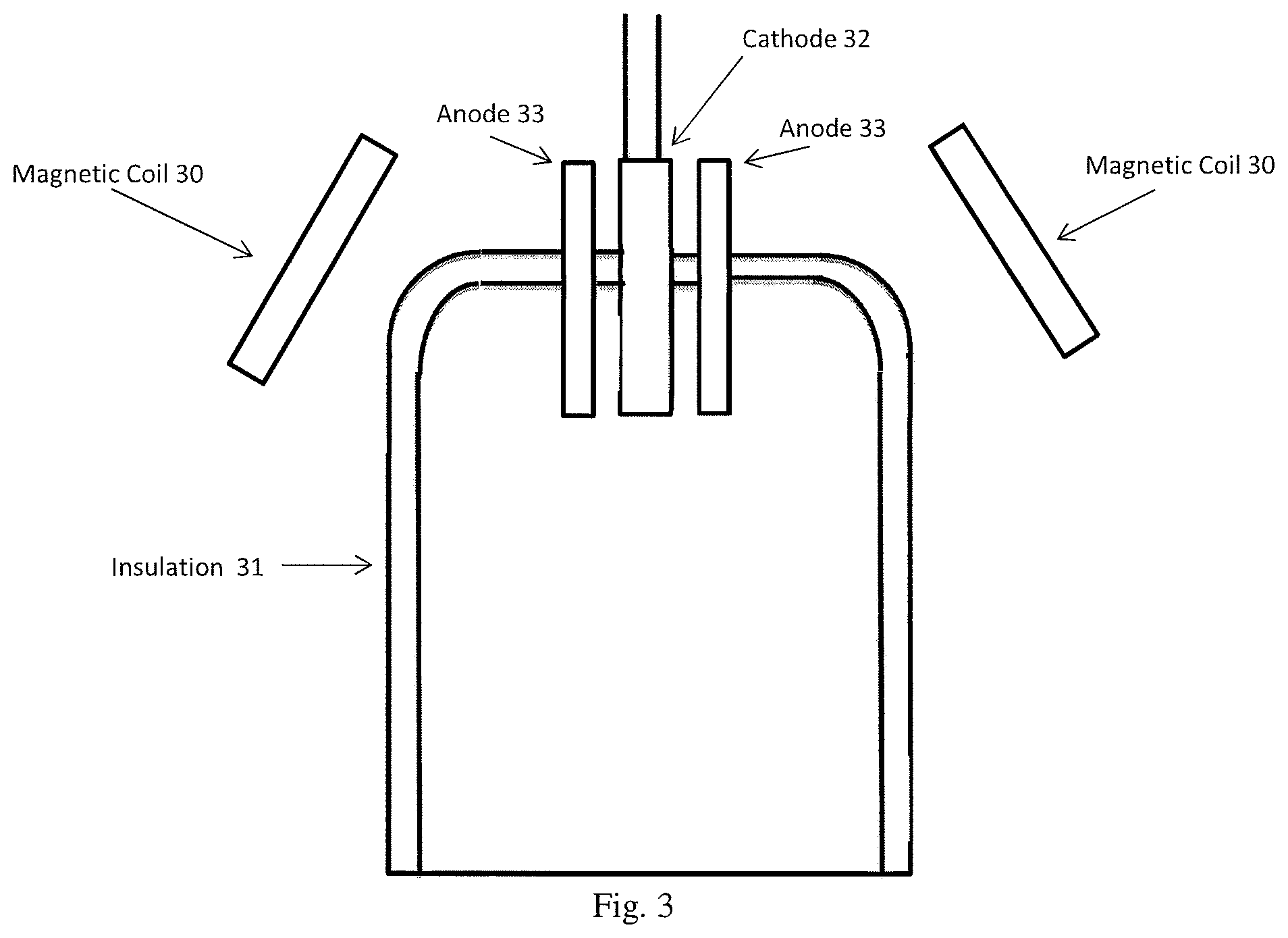
[0027] Typically non-transferred arc plasma torches use water cooled metal electrodes. It is also typical that a tungsten cathode and copper anode be used. These electrodes wear away slowly during use but typically do not break off in large chunks. As described herein, graphite electrodes are typically used to get higher thermal efficiency due to less need for water cooling. But graphite electrodes can break off in large chunks that can cause shorts between electrodes if the chunks do not fall out of the electrical path. In addition, plasmas produced with gas compositions over 90% hydrogen typically erode tungsten and copper electrodes very quickly, resulting in higher operating costs and significant downtime for electrode repair and replacement. The use of graphite electrodes as described herein are much more resistant to erosion in the hydrogen plasma and also much less costly to replace as they erode. But because the use of graphite electrodes results in the plasma torch electrodes being at much higher temperature, metallic magnetic coils are not practical to install near electrodes as shown, for example, in FIG. 2, and the coils (30) must be installed farther away from the electrodes (cathodes (32) and anodes (33)), i.e. outside or near the outer boundaries of an insulated shell (31), as shown, for example, in FIG. 3.
[0028] As shown in FIG. 1, metal electrode non-transferred plasma torches can be arranged at angles around an axially symmetrical reactor. A different configuration, however, is required for using multiple graphite electrode plasma torches because of magnetic coil temperature limitations, magnetic field interference, and graphite erosion patterns.
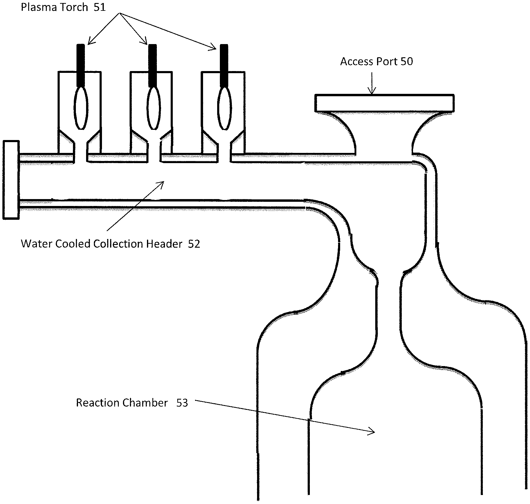
[0029] FIG. 4 shows a typical basic configuration for a horizontal plasma heated reaction chamber (44) and multiple vertically oriented plasma torches (41) in chambers using two electrode graphite plasma torch technology, having an access port (40) and a water or gas cooled collection header (43). The insulated gas chamber (42) contains a lining which can be water or gas cooled as well, for example. As used herein, plasma torches which are described as vertically or substantially vertically oriented include torches whose orientation is within 20 degrees of a vertical axis.
[0030] Scale up of the two electrode graphite plasma torch for heating pure hydrogen has been challenging at best. For example, scale up has been limited by the availability of commodity grade graphite required for scale up. To build a vertically oriented graphite plasma torch using concentric electrode technology would require the use of more expensive iso-molded graphite or the use of barrel stave construction, both of which would result in a significant cost increase in the electrode material, a consumable in any process that utilizes this technology. The size of the plasma torch is dictated by the production capacity of the reactor. The required vertical or substantially vertical orientation of the torch and the way the torch is oriented along the axis of the reactor would typically result in a requirement for a vertical reactor. The inability to generate plasma heating at sufficient megawatts (MW) of power would result in higher cost per ton for a reactor because it limits the size of the reactor. The vertical orientation of a torch that is integral in the reactor could result in a higher installed cost of the reactor if it is then installed vertically. Decoupling the torch from the reactor could allow the installation of the reactor horizontally, which is typically of lower cost to install and an easier-to-maintain configuration.
[0031] Developing a method to install multiple hydrogen plasma torches in parallel to feed a common reactor results in the ability to scale the reactor up almost indefinitely. This impacts overall plant cost because for each reactor, because reduction or elimination of multiple inlet lines, control valves, and heat exchangers has a significant effect on cost, not to mention the significant increase in reactor capacities, e.g., up to 5 times or more what has been able to be generated in the past, i.e., the development of a plasma reactor with full industrial scale capacity with a significant cost advantage. And while the reactors described herein can scaled to product, for example, up to 5,000 tons of carbon black per year, they can also be scaled to produce up to 20,000 tons, up to 40,000 tons, or more.
[0032] In addition to the above, the ability to separate the plasma chamber from the reactor chamber with a water or gas cooled collection header in between allows for multiple advantages over what has been done in the past, some of which are, for example: the ability to control plasma flow to multiple reactors using a central plasma production unit. For example, carbon black reactors take on various dimensions for making different grades. A reactor for making N-234 carbon black is typically much smaller than a reactor for making N-550 carbon black. By separating the plasma chamber and plasma torch from the reactors allows for the installation of multiple reactors, of relatively low cost, on a single hydrogen collection header. This can allow for switching between the reactors, e.g., with conventional water cooled knife gate valves or flange spool pieces.
[0033] As described herein, this system can produce multiple grades, one grade at a time. The process and system described herein have the capability to make different grades with different reactor conditions, one grade at a time, rather than making multiple grades at the same time. Or multiple grades can be made in the respective multiple reactors with different reactor conditions present in the multiple reactors, i.e., capability to make a range of grades of carbon black with the individual grades being made depending on the respective reactor conditions. The particles making up a grade will span a wide range of grades, with the bulk properties needing to meet a set of specific bulk properties. For example, carbon black has a surface chemistry particularly suited to plastic applications such as wire and cable and utility plastics. This comes from the black having a more hydrophobic surface chemistry, sometimes referred to a dead or pure surface.
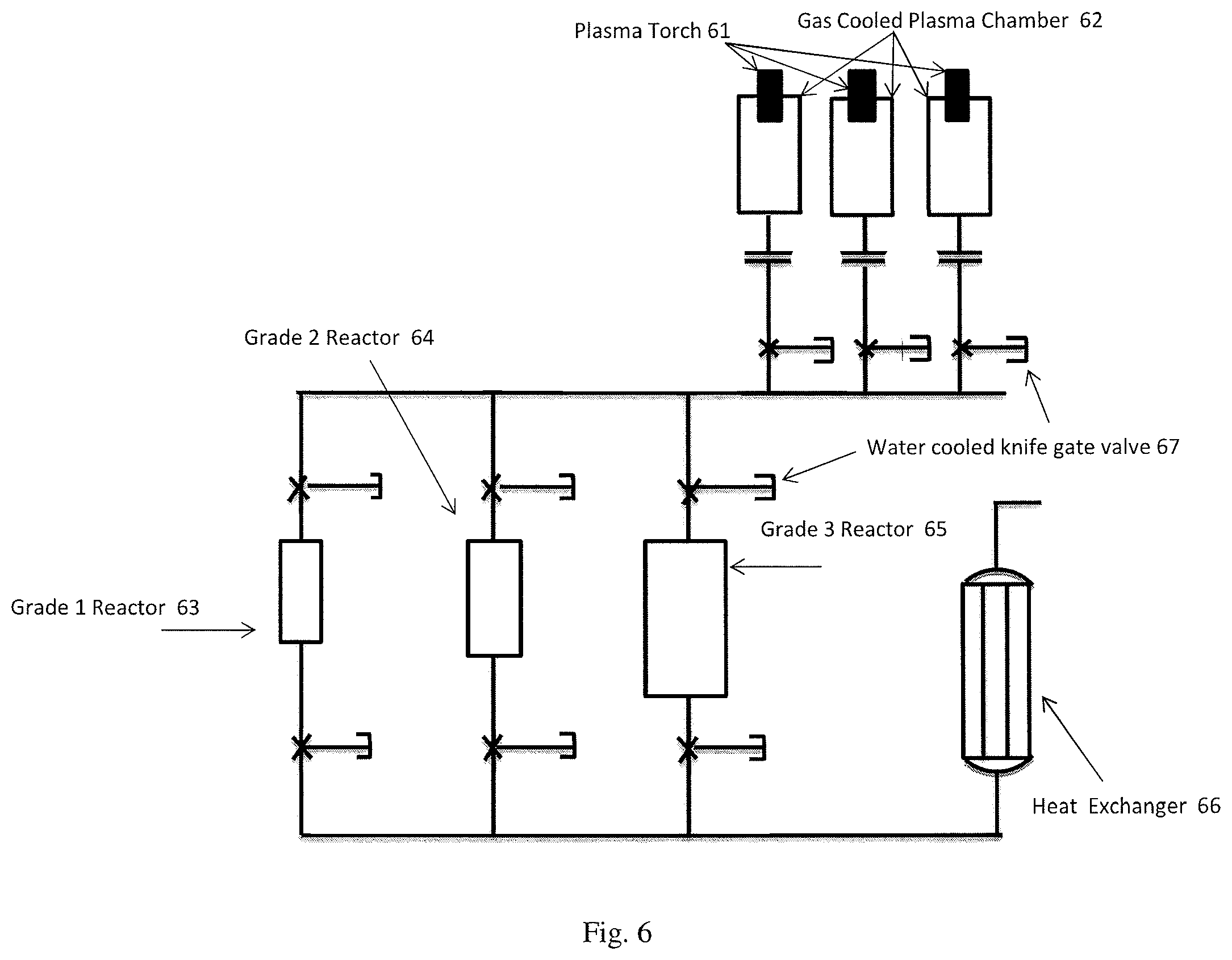
[0034] By increasing the number of plasma torches feeding a system, much higher reliability could be achieved for running the reactors almost continually. See, for example, FIG. 6 which shows schematically vertically oriented plasma torches (61) in gas cooled plasma chambers (62) connected to multiple reactors (63, 64, 65) designed to produce different grades, and a single heat exchanger (66); ability to remove individual plasma torches one at a time for inspection, maintenance, and/or replacement while other plasma torches are running and continuing to produce heat into the process. This could be achieved by means of a water cooled knife gate valves (67) and a nitrogen purge, one example of which is also shown schematically in FIG. 6; in the case where vertical orientation of a reactor is desired (see, for example, FIG. 5), or required, plasma torches could still be installed at or near ground level to help reduce installation costs and maintenance costs.
[0035] It is also typical in this field to install and align plasma torches axially with a production vessel. However, with the system as described herein, there is the possibility of the use of an access port (40) aligned with the axis of the production vessel, e.g, as shown schematically in FIG. 4. See also FIG. 5, which similarly shows a system with plasma torches (51), water or gas cooled collection header (52), reaction chamber (53), and access port (50). Such access ports allow for maintenance access, visibility with a camera or borescope, the use of a central axis injector, and other clear advantages as well.
Example
[0036] Hydrogen gas is run in parallel past three sets of vertically oriented conventional plasma electrodes to generate a temperature of about 3000.degree. C. in the plasma forming zone. Each set of plasma electrodes generates about 3 MW of thermal power into each parallel stream of approximately 1380 nanometers.sup.3 per hour (Nm.sup.3/hr) of hydrogen. The plasma formed then flows into a gas cooled collection heater with a combined flow rate of about 4140 Nm.sup.3/hr prior to flowing into the reaction chamber. It is at this point as the plasma flows into the reaction chamber that methane gas is injected into the plasma at a mass flow rate between about 1600 and about 2200 kilogram (kg)/hr. The plasma-methane gas mixture then flows rapidly into a horizontally oriented reaction zone resulting in the production of a carbon black.
[0037] Thus, the scope of the invention shall include all modifications and variations that may fall within the scope of the attached claims. Other embodiments of the invention will be apparent to those skilled in the art from consideration of the specification and practice of the invention disclosed herein. It is intended that the specification and examples be considered as exemplary only, with a true scope and spirit of the invention being indicated by the following claims.
* * * * *
D00000
D00001
D00002
D00003
D00004
XML
uspto.report is an independent third-party trademark research tool that is not affiliated, endorsed, or sponsored by the United States Patent and Trademark Office (USPTO) or any other governmental organization. The information provided by uspto.report is based on publicly available data at the time of writing and is intended for informational purposes only.
While we strive to provide accurate and up-to-date information, we do not guarantee the accuracy, completeness, reliability, or suitability of the information displayed on this site. The use of this site is at your own risk. Any reliance you place on such information is therefore strictly at your own risk.
All official trademark data, including owner information, should be verified by visiting the official USPTO website at www.uspto.gov. This site is not intended to replace professional legal advice and should not be used as a substitute for consulting with a legal professional who is knowledgeable about trademark law.