Clamshell Case for Holding Blister Pack
Giannopoulos; Peter ; et al.
U.S. patent application number 16/672793 was filed with the patent office on 2020-05-07 for clamshell case for holding blister pack. The applicant listed for this patent is Peter DeLisle Giannopoulos. Invention is credited to Joshua J. DeLisle, Peter Giannopoulos.
| Application Number | 20200140150 16/672793 |
| Document ID | / |
| Family ID | 70457412 |
| Filed Date | 2020-05-07 |
| United States Patent Application | 20200140150 |
| Kind Code | A1 |
| Giannopoulos; Peter ; et al. | May 7, 2020 |
Clamshell Case for Holding Blister Pack
Abstract
A case with a top portion and a bottom portion connected by a hinge at one end and arranged to be coupled together and released by a clasp at the other end. The bottom carries structure that is constructed and arranged to hold a blister pack between opposing sides and a stop.
| Inventors: | Giannopoulos; Peter; (Walpole, MA) ; DeLisle; Joshua J.; (Hanover, MA) | ||||||||||
| Applicant: |
|
||||||||||
|---|---|---|---|---|---|---|---|---|---|---|---|
| Family ID: | 70457412 | ||||||||||
| Appl. No.: | 16/672793 | ||||||||||
| Filed: | November 4, 2019 |
Related U.S. Patent Documents
| Application Number | Filing Date | Patent Number | ||
|---|---|---|---|---|
| 62754668 | Nov 2, 2018 | |||
| Current U.S. Class: | 1/1 |
| Current CPC Class: | B65D 43/16 20130101; B65D 43/162 20130101; A45C 2011/007 20130101; B65D 43/22 20130101; B65D 77/046 20130101 |
| International Class: | B65D 43/16 20060101 B65D043/16; B65D 43/22 20060101 B65D043/22 |
Claims
1. A case with an interior and an exterior, the case comprising: a top portion and an opposing bottom portion, each comprising; two opposing sides; a hinge end; and an opening end opposing the hinge end; a hinge connecting the top and bottom portions at each hinge end; a closure system that releasably connects the opening ends of the top and bottom portions; at least one overhanging ledge between the two opposing sides of the bottom portion, the at least one overhanging ledge having a lower side; and a generally flat surface in the bottom portion; wherein the at least one overhanging ledge is spaced from the generally flat surface defining a slot with a height, through which edges of a blister pack may slide so the blister pack is held between the at least one overhanging ledge and the generally flat surface.
2. The case of claim 1, the closure system comprising: a clasp; a catch; and at least two tabs; wherein the clasp is on either the top portion or the bottom portion and the catch and tabs are on the opposing portion; wherein the closure system is opened by applying increasing force upon the clasp toward the tabs, and against the tabs toward the clasp, until the clasp is released from the catch, allowing the case to open; and wherein the closure system is closed by applying an increasing force upon the top portion toward the bottom portion, and upon the bottom portion toward the top portion, until the clasp is pushed beyond, and retained by the catch, creating a volume in the interior in which a blister pack may be stored.
3. The case of claim 2, further comprising a stop that is proximate the hinge end of the bottom portion, the stop extending to at least the height of the slot from the generally flat surface, such that a blister pack may be held in place by generally flat surface, the at least one overhanging ledge, and the stop.
4. The case of claim 3, wherein the hinge is a living hinge.
5. The case of claim 4, further comprising a plurality of protrusions on the exterior of the case to allow a user to easily grasp the case.
6. The case of claim 5, wherein the plurality of protrusions are on the two opposing sides of the top and bottom portions proximate the opening end.
7. The case of claim 6, further comprising at least one side face in the interior of the case, wherein the at least one side face is generally perpendicular to the lower side of the at least one overhanging ledge.
8. A case with an interior and an exterior, the case comprising: a top portion and an opposing bottom portion, each comprising; two opposing sides; a hinge end; and an opening end opposing the hinge end; a hinge connecting the top and bottom portions at each hinge end; a closure system that releasably connects the opening ends of the top and bottom portions; at least two rails extending from the bottom portion, each rail having an upper surface, the upper surfaces defining a slide plane; at least one overhanging ledge between the two opposing sides, the at least one overhanging ledge having a lower side, the lower side defining a retention plane; wherein the retention plane is spaced from the slide plane, allowing edges of a blister pack to slide between the slide plane and the retention plane.
9. The case of claim 8, further comprising a stop that is proximate the hinge end of the bottom portion, the stop intersecting the slide plane and the retention plane, such that a blister pack may be held in place by the rails, the at least one overhanging ledge, and the stop.
10. The case of claim 9, wherein the closure system further comprising: a clasp; a catch; and at least two tabs; wherein the clasp is on either the top portion or the bottom portion and the catch and tabs are on the opposing portion; wherein the closure system is opened by applying increasing force upon the clasp toward the tabs, and against the tabs toward the clasp, until the clasp is released from the catch, allowing the case to open; and wherein the closure system is closed by applying an increasing force upon the top portion toward the bottom portion, and upon the bottom portion toward the top portion, until the clasp is pushed beyond, and retained by the catch, creating a volume in the interior in which a blister pack may be stored.
11. The case of claim 10, wherein the hinge is a living hinge.
12. The case of claim 11, further comprising a plurality of protrusions on the exterior of the case to allow a user to easily grasp the case.
13. The case of claim 12, wherein the plurality of protrusions are on the two opposing sides of the top and bottom portions proximate the opening end.
14. The case of claim 13, further comprising at least one side face in the interior of the case, wherein the at least one side face is generally perpendicular to the lower side of the at least one overhanging ledge.
15. A case with an interior and an exterior, the case comprising: a top portion and a bottom portion, each comprising; two opposing sides; a hinge end; and an opening end opposing the hinge end; a living hinge connecting the top and bottom portions at each hinge end; a closure system, comprising: a clasp; a catch; and at least two tabs; at least one overhanging ledge between the two opposing sides, the at least one overhanging ledge having a lower side, the lower side defining a retention plane; at least two rails extending from the bottom portion, each rail having an upper surface, the upper surfaces defining a slide plane; a stop that is proximate the hinge end of the bottom portion; a plurality of protrusions on the exterior of the case, on the two opposing sides of the top and bottom portions proximate the opening end, to allow a user to easily grasp the case; and at least one side face in the interior of the case; wherein the clasp is on either the top portion or the bottom portion and the catch and tabs are on the opposing portion; wherein the closure system is opened by applying an increasing force upon the clasp toward the tabs, and against the tabs toward the clasp, until the clasp is released from the catch, allowing the case to open; wherein the closure system is closed by applying an increasing force upon the top portion toward the bottom portion, and upon the bottom portion toward the top portion, until the clasp is pushed beyond, and retained by the catch, creating an interior volume within the case in which a blister pack may be stored; wherein the slide plane is spaced from the retention plane, allowing edges of a blister pack to slide between the slide plane and the retention plane; wherein the at least one side face is generally perpendicular to the lower side of the at least one overhanging ledge; and wherein the stop is intersected by the slide plane and the retention plane, such that a blister pack may be held in place by the rails, the at least one overhanging ledge, the at least one side face, and the stop.
Description
CROSS-REFERENCE TO RELATED APPLICATION
[0001] This application claims priority from Provisional Application 62/754,668, filed on Nov. 2, 2018, the disclosure of which is incorporated herein by reference.
BACKGROUND
[0002] Naloxone is an example of a medicine that sometimes needs to be carried by first responders such as police officers, firemen and EMTs. Naloxone comes in a small vial which may be contained within a blister pack (BP) in order to protect the vial. Naloxone can be administered with a nasal applicator/atomizer or a medicine atomizer/applicator. First responders thus need to carry a BP with one or more vials of naloxone (and/or other medicines) and one or more applicators. Often medicine vials are carried in a cardboard container in a uniform pocket, where they are subject to degradation.
SUMMARY
[0003] Featured in this disclosure is a clamshell-type case; a container that opens and closes. The case is constructed and arranged to hold medicine. In the specific non-limiting embodiment shown in the drawings, the medicine is naloxone, which is a liquid that can be administered nasally or IV/IM, that is contained in a blister pack (BP). The BP may contain a syringe or a nasal applicator or any other type of applicator for the medicine, and the BP is carried within the case. The case may then be carried in a zipper bag, pouch, holster or pocket of the type that is utilized by police, firefighters, EMTs, military personnel, or other first responders.
[0004] The case in the non-limiting examples disclosed herein in detail is a hard-shell, one-piece construction made by injection molding of an appropriate plastic such as polypropylene or the like, designed to carry a Blister Pack (BP). A typical BP has a firm, two-sided, generally rectangular shaped lower portion that is flat on its top and bottom surfaces with edges around its perimeter. The BP has an upper portion that comprises a volume enclosed by a plastic film that is sealed to the top surface of the lower portion, leaving flanges that extend from the seal to its edges. The case protects the medicine within the BP and from degradation due to sunlight and weather. Also, the case provides crush and impact protection for the medicine and applicators, which is particularly important if medicines are in glass containers. Further, the case can be used to store the medicine and the applicator in a home or business or the like, and also is a convenient means to hold used components for disposal. The shape of the container fits into most hands and offers a secure grip when hands may be cold or wet. The container snaps shut, thus securing its contents.
[0005] In one aspect, the clamshell case includes a bottom portion and a top portion that are connected by a hinge. The bottom portion has a structure that is adapted to removably hold a Blister Pack (BP) filled with medicine and/or applicators. The top portion is constructed and arranged to movably cover a BP that is held in the bottom portion, thereby protecting the BP from damage. There is a releasable case closure system that opposes the hinge and releasably maintains the two portions in a closed position. The portions may be variously shaped with edges configured and arranged to abut or otherwise interface with each other.
[0006] The closure system may comprise one of a variety of possible latching mechanisms to secure the closure, and to enable the opening of the clamshell case. For example, the closure system may comprise a pair of tabs on either side of a protruding catch and an opposing protruding clasp. The tabs and protruding catch may be on the edge of the bottom portion, and the clasp may extend from the top portion, such that when the bottom and top portions abut or otherwise close against each other, the clasp may extend beyond, and be retained by the catch to maintain the closure of the clamshell case. The case may be opened by applying enough force against the top portion and toward the bottom portion, to overcome the retention of the clasp by the catch. A user may do this with one hand, by simply placing a finger on one of the tabs and an opposing thumb against the clasp and squeezing toward each other until the clasp is pushed over, and released from, the catch. Closure may be achieved with one hand as well, by squeezing the first portion against the second portion, thereby pushing the clasp with enough force to extend beyond, and be retained by, the catch. A wide variety of mechanisms are available in the present state of the art to open and close the case. In this clamshell case for holding medicine blister packs, it is preferred that the closure system may be operated with a single hand as first responders are often involved with complicated situations involving multiple activities. Other possible closure systems may include releasable hook and loop fastening materials, or there may be a single protrusion on one the portions and a loop on the other portion, the loop able to be retained by the protrusion.
[0007] In another aspect, the bottom portion of the case may have a generally flat surface in its interior, the generally flat surface on which a blister pack (BP) may easily slide into and out of the case. The bottom portion of the case may also comprise a plurality of overhanging ledges which protrude from the interior sides of the bottom portion, the ledges having lower sides spaced from the generally flat surface. The bottom surface of a BP lower portion may slide upon the generally flat surface while the BP lower portion is held in place by the overhanging ledges. The case may have a stop that extends upward from the interior bottom portion and is proximate the hinge end of the bottom portion. The BP may slide between the overhanging ledges and the generally flat surface until one of the BP edges makes contact with the stop. This contact with the stop assures that the BP has been fully inserted within the interior of the case, thereby allowing the bottom and top portions of the case to close against each other, without coming in contact with the BP.
[0008] Another embodiment of the case may have a plurality of overhanging ledges and a plurality of rails in the interior bottom portion so the case may removably hold a medicine blister pack (BP). The plurality of overhanging ledges protrude from the interior sides and they have lower sides that generally define a retention plane. The plurality of rails extend from the bottom portion and may have upper surfaces that define a slide plane. The bottom surface of a BP lower portion may slide upon the slide plane allowing the BP lower portion to be secured between the slide plane and the retention plane. The case may comprise side faces which protrude from the interior sides of the case, the side faces may generally oppose each other and may be generally perpendicular to the lower sides of the overhanging ledges. The side faces provide lateral support to the BP that is held between the slide plane and the retention plane in the interior of the case. The case may have a stop that intersects with the retention plane and the slide plane and is proximate the hinge end of the interior bottom portion of the case. A typical BP is generally rectangular in shape with two sets of opposing edges, each set generally perpendicular to the other set. The BP may slide upon the upper surfaces of the rails when it is being inserted or removed from the interior of the case, so that it may be held in place between the retention plane and the slide plane. The BP may slide between the retention plane and the slide plane until one of the BP edges makes contact with the stop. This contact with the stop assures that the BP has been fully inserted within the interior of the case, thereby allowing the bottom and top portions of the case to close against each other, without coming into contact with the BP.
[0009] Another embodiment of the case includes a single overhanging ledge in the interior of the bottom portion. The single overhanging ledge may be generally U-shaped comprising two opposing side lengths and a middle length, the middle length proximate and generally parallel to the hinge. The single overhanging ledge functions similarly to the embodiment with a plurality of overhanging ledges, except that the edges of a BP are secured under the lower side of the entire overhanging ledge. This embodiment may also comprise a side face for at least a portion of the middle length, functioning as a stop for a BP that is inserted under the overhanging ledge in the interior of the case.
BRIEF DESCRIPTION OF THE DRAWINGS
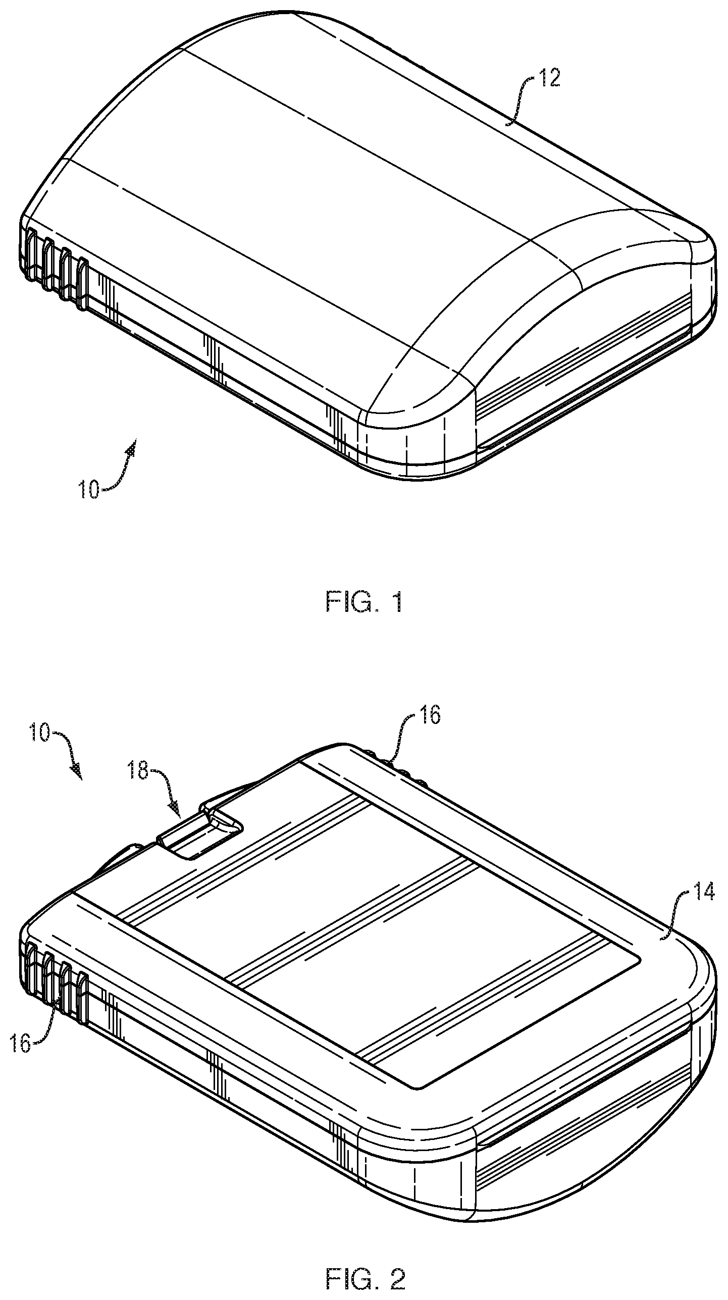
[0010] FIG. 1 is a perspective view of the front, side, top of a case in the closed configuration.
[0011] FIG. 2 is a perspective view of the front, side, bottom of a case in the closed configuration.
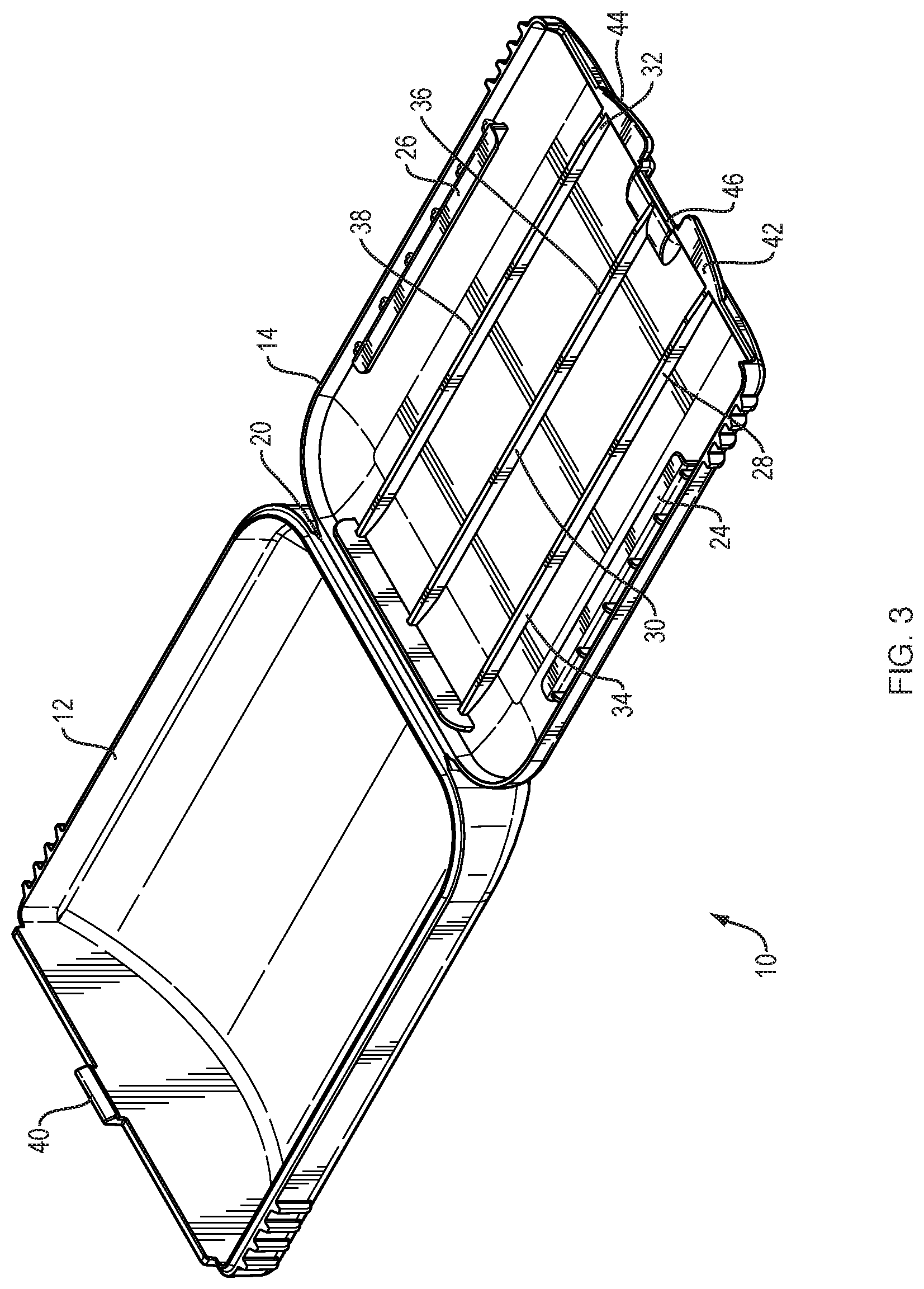
[0012] FIG. 3 is a perspective view of the case in the open configuration.
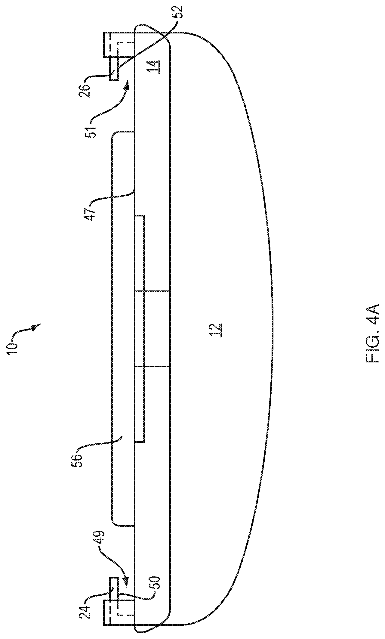
[0013] FIG. 4A is a front view of the case with a generally flat surface, the case in the open configuration.
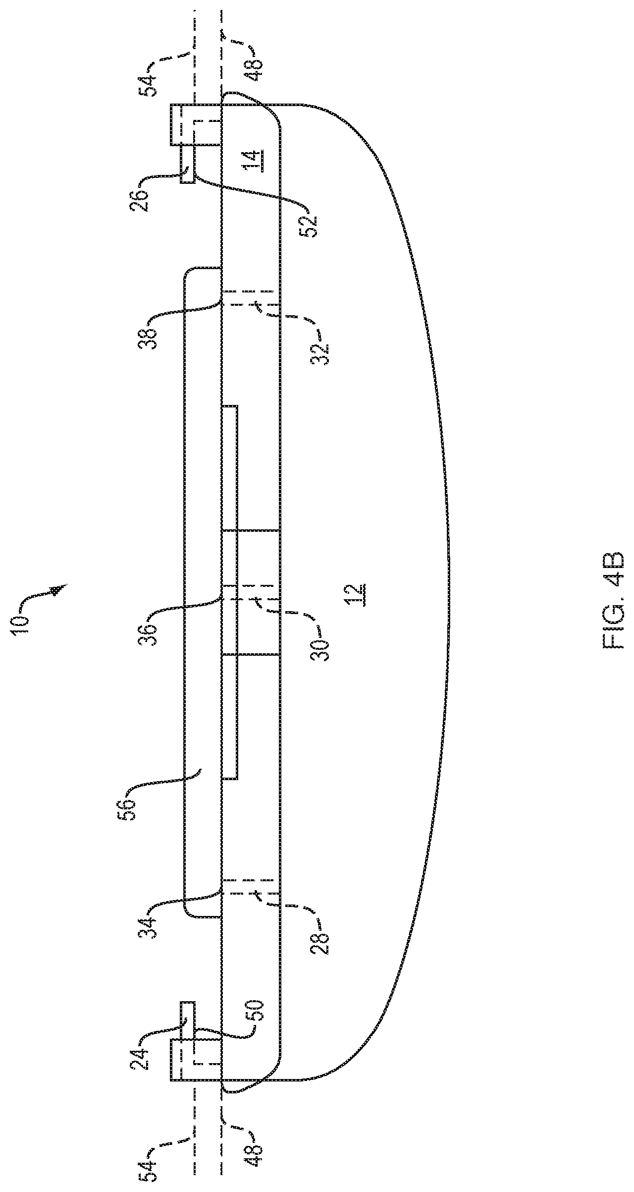
[0014] FIG. 4B is a front view of the case with a plurality of rails, the case in the open configuration.
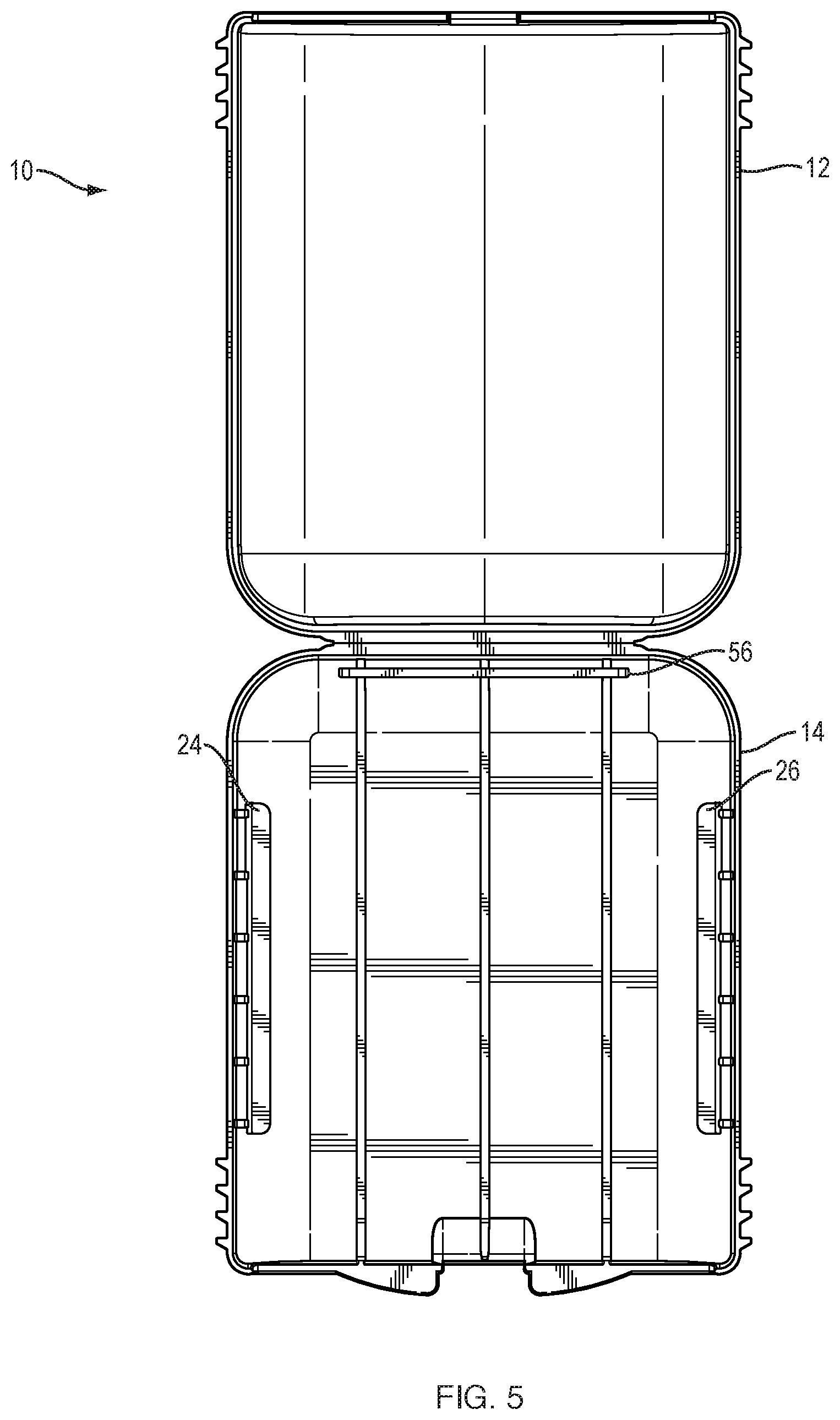
[0015] FIG. 5 is a top view of the case in the open configuration with two overhanging ledges.
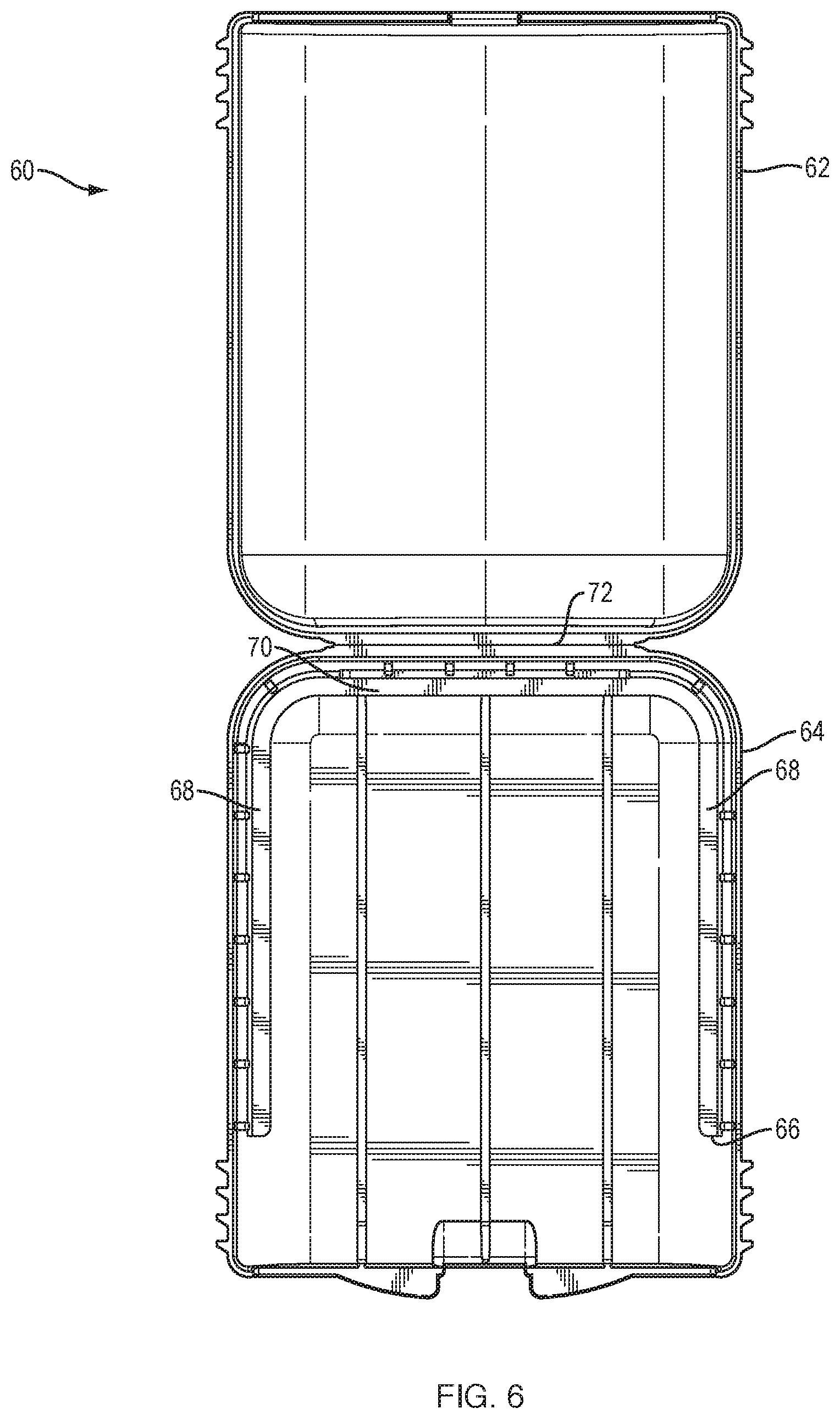
[0016] FIG. 6 is a top view of the case in the open configuration with a single overhanging ledge.
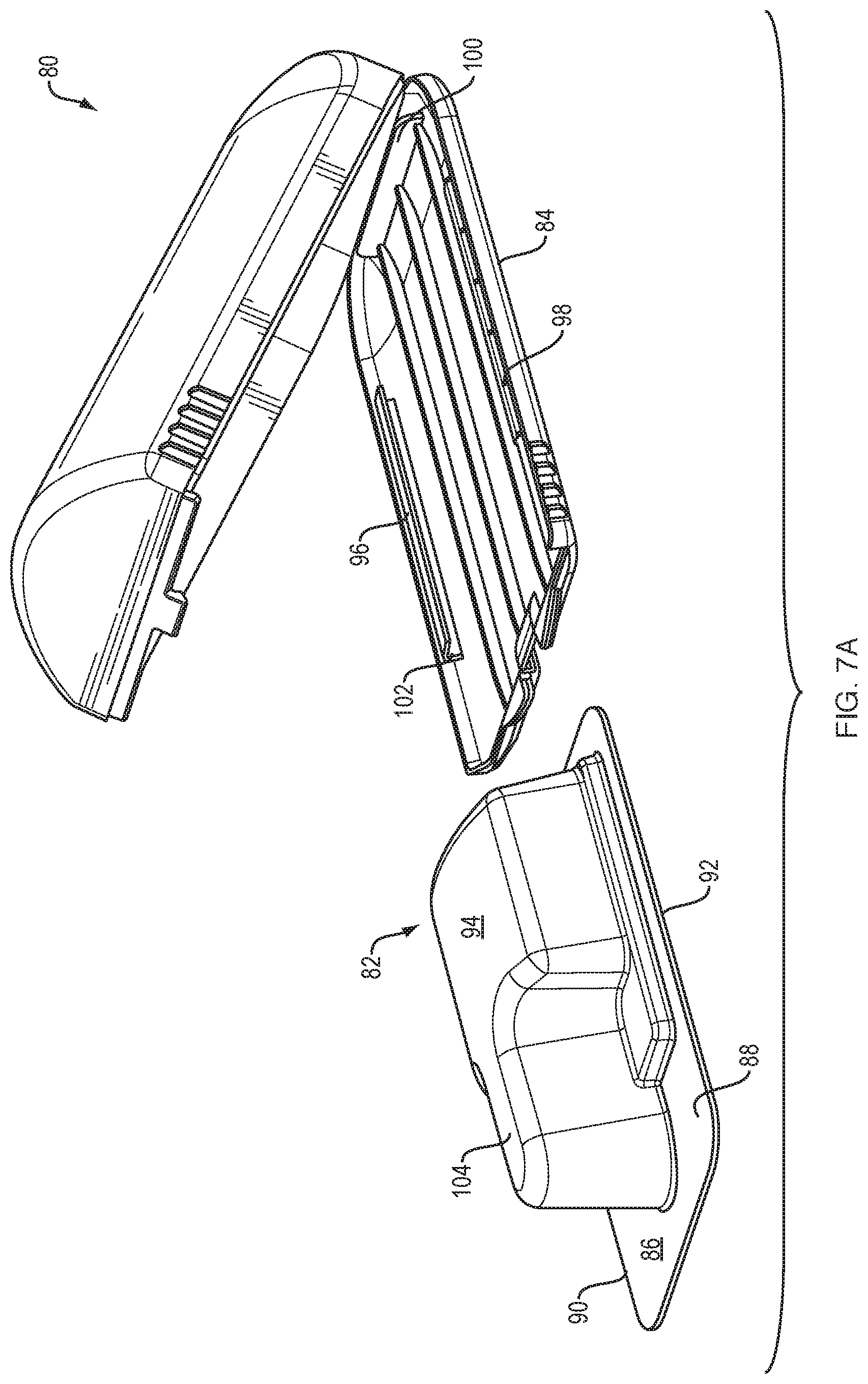
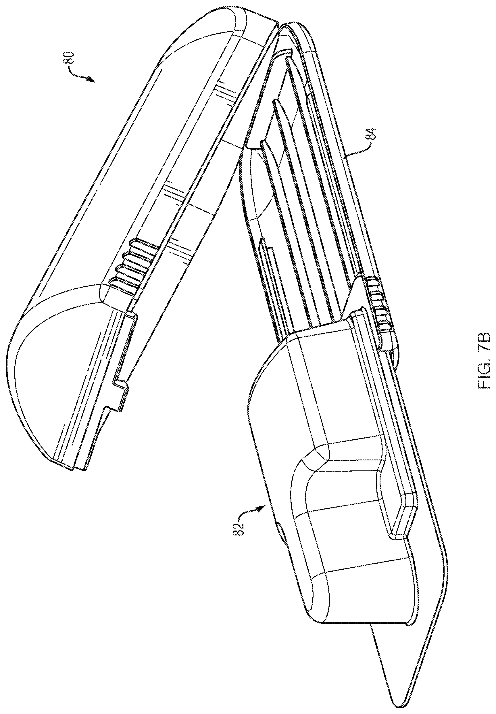
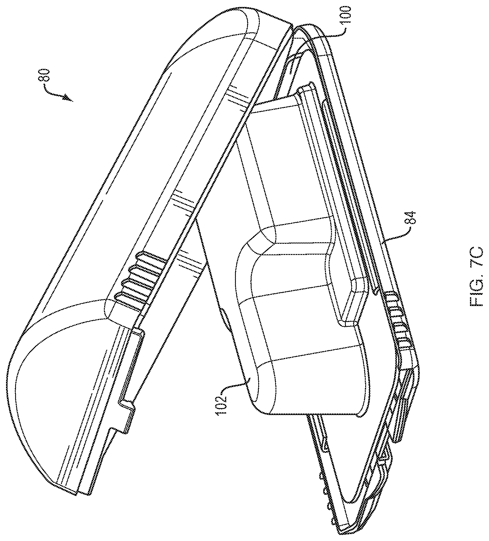
[0017] FIGS. 7A, 7B, 7C are three sequential views of a blister pack being inserted into the case.
DETAILED DESCRIPTION
[0018] FIGS. 1 and 2 show case 10, which has a clamshell-type construction, in a closed configuration. Top portion 12 of case 10 abuts or otherwise connects with bottom portion 14 of the case. Grips 16 overlap top portion 12 and bottom portion 14 and allow a user to quickly grasp the case. The closed configuration is maintained by closure system 18 which can be manipulated in order to open the case.
[0019] FIG. 3 shows case 10 in an open configuration with top portion 12 and bottom portion 14 connected together via hinge 20. Bottom portion 14 comprises overhanging ledges 24, 26 and rails 28, 30, 32 with upper surfaces 34, 36, 38 respectively. Clasp 40 is on top portion 12. Tabs 42, 44 and catch 46 are on bottom portion 14. The case may be placed in the closed configuration by applying a force upon top portion 12 toward bottom portion 14 until clasp 40 is pushed beyond, and secured by, catch 46.
[0020] FIG. 4A shows the front of case 10 in the open configuration with top portion 12 extending behind bottom portion 14. Overhanging ledges 24 and 26 can be seen on either side of bottom portion 14 and are spaced from generally flat surface 47, creating slots 49, 51 between the overhanging ledges 24, 26 and the generally flat surface 47. Stop 56 extends upward from bottom portion 14 at least to the height of overhanging ledges 24, 26 so that a BP inserted through the slots will come in contact with the stop
[0021] FIG. 4B shows the front of case 10 in the open configuration with top portion 12 extending behind bottom portion 14. Rails 28, 30, and 32 can be seen extending from the bottom portion 14 via dashed lines, with upper surfaces 34, 36, 38 of rails 28, 30, and 32 defining slide plane 48. Overhanging ledges 24 and 26 can be seen on either side of bottom portion 14 and are spaced from slide plane 48. Lower sides 50, 52 of overhanging ledges 24, 26 define retention plane 54 which is spaced from slide plane 48. Stop 56 extends upward from bottom portion 14 at least to the height of overhanging ledges 24, 26, and stop 56 intersects with slide plane 48 and retention plane 54, allowing a BP to slide into the case between the retention plane and the slide plane until it comes in contact with the stop.
[0022] FIG. 5 shows a top view of case 10 in the open configuration with top portion 12 and bottom portion 14, two overhanging ledges 24, 26, and stop 56.
[0023] FIG. 6 shows a top view of case 60 in the open configuration with top portion 62 and bottom portion 64 with single overhanging ledge 66. The single unitary overhanging ledge is generally U-shaped with two opposing side lengths 68 and middle length 70, the middle length proximate and generally parallel to hinge 72. The single overhanging ledge functions similarly to the embodiment with a plurality of overhanging ledges, in that its lower side defines the retention plane. However, the side lengths and the middle length of the single overhanging ledge are continuous and unitary, with the middle length 70 functioning as an overhanging ledge a well as a stop.
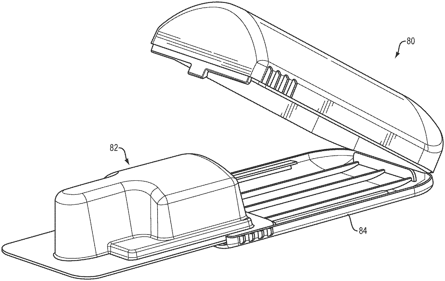
[0024] FIGS. 7A, 7B, and 7C show perspective views of the front, side, top of case 80 with blister pack (BP) 82 sequentially inserted within bottom portion 84 of the case. A typical BP has a firm, two-sided, generally rectangular shaped lower portion 86 that is flat on its top surface 88 and bottom surface (not visible) with side edges 90, 92 along the BP perimeter. The BP has an upper portion 92 that comprises a volume enclosed by a plastic film that is sealed to the top surface 88 of lower portion 86, leaving generally flat side edges 90, 92. BP side edges 90, 92 slide under overhanging ledges 96, 98 which, along with stop 100 and side face 102, secure BP 82 within case 80. When the BP 82 makes contact with stop 100 it assures that BP 82 has been fully inserted within case 80, making it possible close case 80 clear of BP 82. Hold 104 allows a user to easily grasp BP 82 for easy extraction from case 80.
[0025] A number of implementations have been described. Nevertheless, it will be understood that additional modifications may be made without departing from the scope of the inventive concepts described herein, and, accordingly, other embodiments are within the scope of the following claims.
* * * * *
D00000
D00001
D00002
D00003
D00004
D00005
D00006
D00007
D00008
D00009
XML
uspto.report is an independent third-party trademark research tool that is not affiliated, endorsed, or sponsored by the United States Patent and Trademark Office (USPTO) or any other governmental organization. The information provided by uspto.report is based on publicly available data at the time of writing and is intended for informational purposes only.
While we strive to provide accurate and up-to-date information, we do not guarantee the accuracy, completeness, reliability, or suitability of the information displayed on this site. The use of this site is at your own risk. Any reliance you place on such information is therefore strictly at your own risk.
All official trademark data, including owner information, should be verified by visiting the official USPTO website at www.uspto.gov. This site is not intended to replace professional legal advice and should not be used as a substitute for consulting with a legal professional who is knowledgeable about trademark law.