Reusable Container Assembly For Modified Atmosphere Packaging Of Goods
Lidster; Perry
U.S. patent application number 16/677384 was filed with the patent office on 2020-05-07 for reusable container assembly for modified atmosphere packaging of goods. The applicant listed for this patent is IFOOD HOLDINGS, INC.. Invention is credited to Perry Lidster.
| Application Number | 20200140143 16/677384 |
| Document ID | / |
| Family ID | 70458275 |
| Filed Date | 2020-05-07 |


| United States Patent Application | 20200140143 |
| Kind Code | A1 |
| Lidster; Perry | May 7, 2020 |
REUSABLE CONTAINER ASSEMBLY FOR MODIFIED ATMOSPHERE PACKAGING OF GOODS
Abstract
A reusable container assembly including, a container having a plurality of tapered sidewalls extending substantially upwardly from a bottom surface forming an opening and an interior space. The bottom surface includes a plurality of feet extending substantially downwardly from the bottom surface. The assembly also includes a lid having a plurality of tapered sidewalls extending substantially downwardly from a top surface, the tapered sidewalls of the lid being configured to receive the tapered sidewalls of the container, such that the lid seals the opening of the container. The top surface of the lid also includes a plurality of raised corners extending substantially upwardly from the top surface, and the feet of the container are configured to receive the raised corners of the lid, when the lid is positioned beneath the container in a stacked configuration.
| Inventors: | Lidster; Perry; (Summerland, CA) | ||||||||||
| Applicant: |
|
||||||||||
|---|---|---|---|---|---|---|---|---|---|---|---|
| Family ID: | 70458275 | ||||||||||
| Appl. No.: | 16/677384 | ||||||||||
| Filed: | November 7, 2019 |
Related U.S. Patent Documents
| Application Number | Filing Date | Patent Number | ||
|---|---|---|---|---|
| 62757049 | Nov 7, 2018 | |||
| Current U.S. Class: | 1/1 |
| Current CPC Class: | B65D 81/263 20130101; B65D 85/505 20130101; B65D 85/50 20130101; B65D 85/52 20130101; B65D 21/0223 20130101; Y02W 30/80 20150501; B65D 81/24 20130101; B65D 1/22 20130101; B65D 25/24 20130101; B65D 25/205 20130101 |
| International Class: | B65D 21/02 20060101 B65D021/02; B65D 25/24 20060101 B65D025/24; B65D 81/26 20060101 B65D081/26; B65D 1/22 20060101 B65D001/22; B65D 85/50 20060101 B65D085/50 |
Claims
1. A reusable container assembly, comprising: a container having a plurality of tapered sidewalls extending substantially upwardly from a bottom surface forming an opening and an interior space, wherein the bottom surface includes a plurality of feet extending substantially downwardly from the bottom surface; and a cover extending over the opening, the cover sealing the opening of the container to the environment while selectively controlling transmission of water vapor, carbon dioxide and oxygen into and out of the container.
2. The container assembly of claim 1, wherein the cover comprises a lid having a plurality of tapered sidewalls extending substantially downwardly from a top surface, wherein the tapered sidewalls of the lid are configured to receive the tapered sidewalls of the container, such that the lid seals the opening of the container, and the top surface further includes a plurality of raised corners extending substantially upwardly from the top surface.
3. The container assembly of claim 2, wherein the feet of the container are configured to receive the raised corners of the lid, when the lid is positioned beneath the container in a stacked configuration.
4. The container assembly of claim 1, wherein each of the plurality of feet comprise a first raised portion extending below a bottom surface of the container and a second raised portion extending below the first raised portion.
5. The container assembly of claim 4, wherein each of the second raised portions of the plurality of feet have an L-shaped configuration with outer surfaces coextensive with corresponding outer surface of tapered side walls of the container.
6. The container assembly of claim 1, wherein when the feet of the container receive the raised corners of a lid of an adjacent container such that the lid of the adjacent container is positioned beneath the container in a stacked configuration, an air gap is formed between the bottom surface of the container and a top surface of the lid of the adjacent container.
7. The container assembly of claim 1, wherein when a plurality of containers are arranged in a stacked and side-by-side arrangement, a plurality of air gaps are formed between adjacent containers along the tapered sides of the containers.
8. The container assembly of claim 1, wherein the top surface of the lid defines a recess configured for retaining an antimicrobial substance, the recess having a plurality of holes therein in fluid communication with an interior of the lid.
9. The container assembly of claim 1, wherein the cover comprises a semipermeable sheet of material disposed over the opening and sealed to the top surface of the container around a perimeter thereof.
10. The container assembly of claim 8, further comprising a semipermeable sheet of material disposed over the recess and sealed to the top surface of the container around a perimeter of the recess, the semipermeable sheet of material limiting passage of oxygen and carbon dioxide while allowing water vapor to pass through the semipermeable sheet of material.
11. A reusable container assembly, comprising: an molded plastic container having a plurality of tapered sidewalls extending substantially upwardly from a bottom surface forming an opening and an interior space; an molded plastic lid having a plurality of tapered sidewalls extending substantially downwardly from a top surface, wherein the tapered sidewalls of the lid are configured to receive the tapered sidewalls of the container, such that the lid seals the opening of the container, and the top surface further includes a plurality of raised corners extending substantially upwardly from the top surface, the top surface of the lid defining a recess configured for retaining an antimicrobial substance, the recess having a plurality of holes therein in fluid communication with an interior of the lid; and a plurality of feet extending substantially downwardly from the bottom surface of the container, the plurality of feet of the container configured to receive the raised corners of the lid, when the lid is positioned beneath the container in a stacked configuration.
12. The container assembly of claim 11, wherein the plurality of tapered sidewalls define a plurality of spaced apart grooves, horizontally oriented and circumscribing the plurality of tapered sidewalls, the plurality of spaced apart grooves configured to direct air flow around the container.
13. The container assembly of claim 12, wherein each of the plurality of feet comprise a first raised portion extending below a bottom surface of the container and a second raised portion extending below the first raised portion, wherein each of the second raised portions of the plurality of feet have an L-shaped configuration with outer surfaces coextensive with corresponding outer surface of tapered side walls of the container.
14. The container assembly of claim 13, wherein when the feet of the container receive the raised corners of a lid of an adjacent container, when the lid of the adjacent container is positioned beneath the one container in a stacked configuration, an air gap is formed between the bottom surface of the container and a top surface of the lid of the adjacent container.
15. The container assembly of claim 11, wherein when a plurality of containers are arranged in a stacked and side-by-side arrangement, a plurality of air gaps are formed between adjacent containers along the tapered sides of the containers.
16. The container assembly of claim 11, further comprising a semipermeable sheet of material disposed over the recess and sealed to the top surface of the lid around a perimeter of the recess, wherein the semipermeable sheet of material limiting passage of oxygen and carbon dioxide while allowing water vapor to pass through the semipermeable sheet of material.
Description
CROSS-REFERENCE TO RELATED APPLICATION
[0001] This application claims priority to U.S. Provisional Patent Application No. 62/757,049, filed on Nov. 7, 2018 for REUSABLE CONTAINER ASSEMBLY FOR MODIFIED ATMOSPHERE PACKAGING OF GOODS, the entirety of which is incorporated by reference in its entirety.
BACKGROUND
Field of the Invention
[0002] The present invention relates generally to reusable containers used to transport goods in modified atmospheric conditions, specifically goods such as produce, flowers and plants.
State of the Related Art
[0003] The use and manufacture of containers to transport produce, flowers and plants is an old and well-known art. Reusable Plastic Containers (RPC) have been used to transport produce in ambient atmospheres. RPC conventionally rely extensively on a porous construction to provide cooling of the goods housed therein, such as produce, which often desiccates the produce, resulting in shrink and loss of postharvest distribution and shelf life of the produce.
[0004] As an alternative to RPC, Modified Active Atmosphere Packaging (MAAP) has been used in an attempt to better prevent produce loss by reducing water loss, produce respiration, and in some cases decay, through the application and utilization of active antimicrobials.
[0005] In conventionally used RPC and MAAP products, container damage is also often a chief concern, as during shipping, transit, and/or storage, these products are often stacked one on top of another, on pallets or on floors. In these situations the container products endure, sometimes significant, structural stresses that can cause failure of the containers, which can result in a total loss of goods stored within the damaged containers.
[0006] Thus, there exists a need in the art to provide a reusable container which utilizes modified atmospheric packaging to better preserve the quality goods, such as, produce, flowers and plants, after transport. The present application provides for the manufacture of beneficial modified atmospheres in an RPC packaging format.
SUMMARY OF THE INVENTION
[0007] According to one aspect of the invention, a reusable container assembly includes: a container having a plurality of tapered sidewalls extending substantially upwardly from a bottom surface forming an opening and an interior space. The bottom surface includes a plurality of tabs or feet extending substantially downwardly from the bottom surface. The assembly also includes a lid having a plurality of tapered sidewalls extending substantially downwardly from a top surface, the tapered sidewalls of the lid being configured to receive the tapered sidewalls of the container, such that the lid seals the opening of the container. The top surface of the lid also includes a plurality of raised corners extending substantially upwardly from the top surface, and the tabs of the container are configured to receive the raised corners of the lid, when the lid is positioned beneath the container in a stacked configuration.
[0008] In another embodiment of the invention, the container is formed as a single unitary piece of molded plastic as by injection molded.
[0009] In another embodiment of the invention, the lid is formed as a single unitary piece of molded plastic as by injection molded.
[0010] In another embodiment, each of the plurality of feet comprise a first raised portion extending below a bottom surface of the container and a second raised portion extending below the first raised portion.
[0011] In yet another embodiment, each of the second raised portions of the plurality of feet have an L-shaped configuration with outer surfaces coextensive with corresponding outer surface of tapered side walls of the container.
[0012] In still another embodiment, when the feet of the container receive the raised corners of a lid of an adjacent container such that the lid of the adjacent container is positioned beneath the container in a stacked configuration, an air gap is formed between the bottom surface of the container and a top surface of the lid of the adjacent container.
[0013] In another embodiment, when a plurality of containers are arranged in a stacked and side-by-side arrangement, a plurality of air gaps are formed between adjacent containers along the tapered sides of the containers.
[0014] In yet another embodiment, the top surface of the lid defines a recess configured for retaining an antimicrobial substance, the recess having a plurality of holes therein in fluid communication with an interior of the lid. A semipermeable sheet of material disposed over the recess and sealed to the top surface of the lid around a perimeter of the recess. The semipermeable sheet of material limits the passage of oxygen and carbon dioxide while allowing water vapor to pass through the semipermeable sheet of material.
[0015] In another embodiment, the plurality of tapered sidewalls of the container define a plurality of spaced apart grooves, horizontally oriented and circumscribing the plurality of tapered sidewalls, the plurality of spaced apart grooves configured to direct air flow around the container.
[0016] These and other aspects of the present invention may be realized in an improved reusable container assembly as shown and described in the following figures and related description.
BRIEF DESCRIPTION OF THE DRAWINGS
[0017] When considered in connection with the following illustrative figures, a more complete understanding of the present invention may be derived by referring to the detailed description. In the figures, like reference numbers refer to like elements or acts throughout the figures. Various embodiments of the present invention are shown and described in reference to the numbered drawings.
[0018] FIG. 1 is a perspective view of a container in accordance with the principles of the present invention;
[0019] FIG. 2 is a bottom view the container shown in FIG. 1;
[0020] FIG. 3 is a side view of the container shown in FIG. 1;
[0021] FIG. 4 is a perspective view of a lid for the container shown in FIG. 1, made of opaque material;
[0022] FIG. 5 is a perspective view of a lid for the container shown in FIG. 1, made of transparent material;
[0023] FIG. 6 is a top view of the lid shown in FIG. 4;
[0024] FIG. 7 is a perspective view of a container assembly, including a container and a lid;
[0025] FIG. 8 is a side view of the container assembly shown in FIG. 7;
[0026] FIG. 9 is a side view of two stacked container assemblies; and
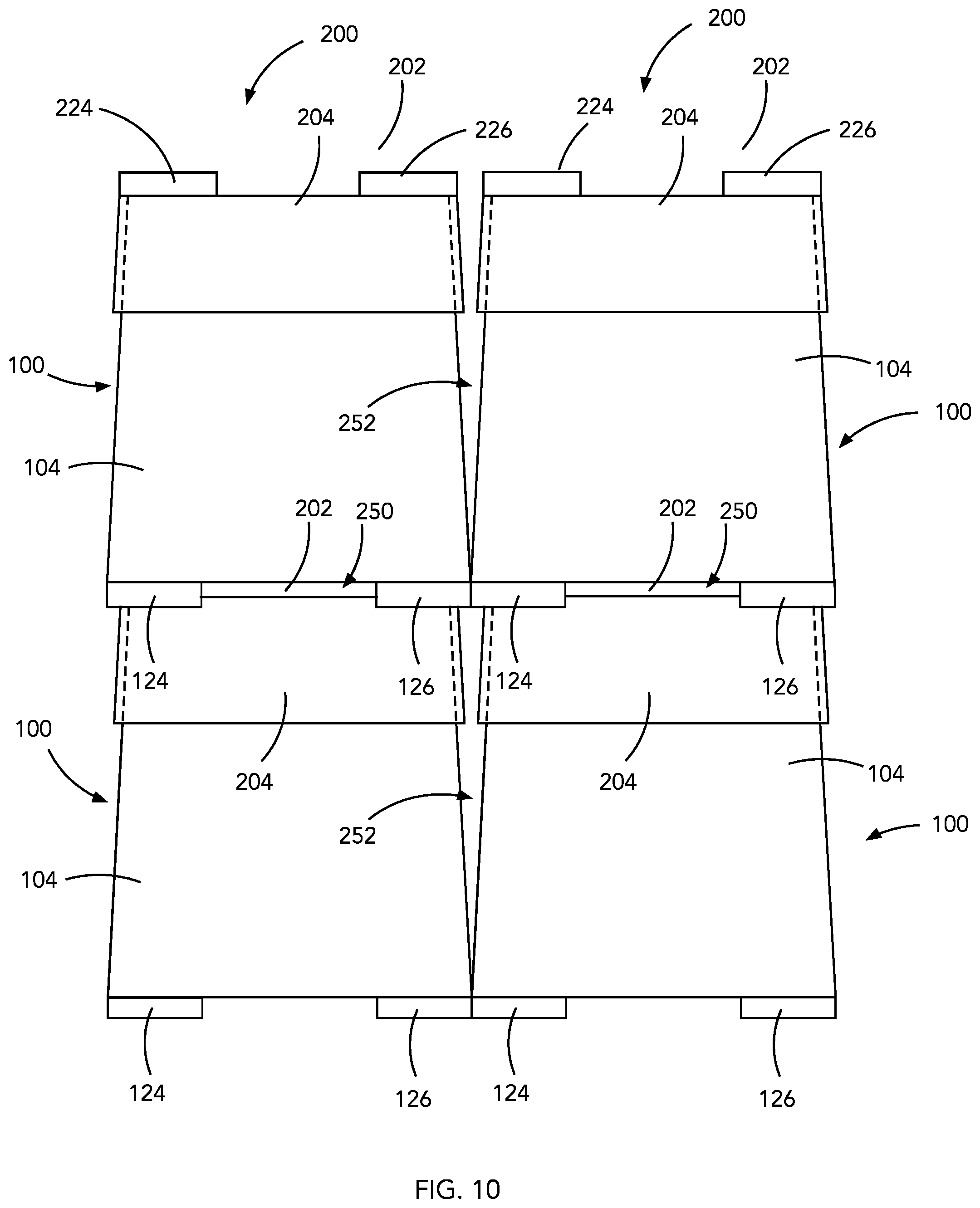
[0027] FIG. 10 is a side view of four stacked container assemblies in a side-by-side arrangement.
[0028] It will be appreciated that the drawings are illustrative and not limiting of the scope of the invention, which is defined by the appended claims. The embodiments shown accomplish various aspects and objects of the invention. It is appreciated that it is not possible to clearly show each element and aspect of the invention in a single figure, and as such, multiple figures are presented to separately illustrate the various details of the invention in greater clarity. Similarly, not every embodiment need accomplish all advantages of the present invention. Elements and acts in the figures are illustrated for simplicity and have not necessarily been rendered according to any particular sequence or embodiment.
DETAILED DESCRIPTION OF THE ILLUSTRATED EMBODIMENTS
[0029] The invention and accompanying drawings will now be discussed in reference to the numerals provided therein so as to enable one skilled in the art to practice the present invention. The drawings and descriptions are exemplary of various aspects of the invention and are not intended to narrow the scope of the appended claims. Unless specifically noted, it is intended that the words and phrases in the specification and the claims be given their plain, ordinary, and accustomed meaning to those of ordinary skill in the applicable arts. It is noted that the inventor can be his own lexicographer. The inventor expressly elects, as his own lexicographer, to use only the plain and ordinary meaning of terms in the specification and claims unless they clearly state otherwise and then further, expressly set forth the "special" definition of that term and explain how it differs from the plain and ordinary meaning. Absent such clear statements of intent to apply a "special" definition, it is the inventor's intent and desire that the simple, plain and ordinary meaning to the terms be applied to the interpretation of the specification and claims.
[0030] The inventors are also aware of the normal precepts of English grammar. Thus, if a noun, term, or phrase is intended to be further characterized, specified, or narrowed in some way, then such noun, term, or phrase will expressly include additional adjectives, descriptive terms, or other modifiers in accordance with the normal precepts of English grammar. Absent the use of such adjectives, descriptive terms, or modifiers, it is the intent that such nouns, terms, or phrases be given their plain, and ordinary English meaning to those skilled in the applicable arts as set forth above.
[0031] Further, the inventors fully informed of the standards and application of the special provisions of 35 U.S.C. .sctn. 112(f). Thus, the use of the words "function," "means" or "step" in the Detailed Description of the Invention or claims is not intended to somehow indicate a desire to invoke the special provisions of 35 U.S.C. .sctn. 112(f), to define the invention. To the contrary, if the provisions of 35 U.S.C. .sctn. 112(f) are sought to be invoked to define the inventions, the claims will specifically and expressly state the exact phrases "means for" or "step for" and the specific function (e.g., "means for filtering"), without also reciting in such phrases any structure, material or act in support of the function. Thus, even when the claims recite a "means for . . . " or "step for . . . " if the claims also recite any structure, material or acts in support of that means or step, or that perform the recited function, then it is the clear intention of the inventor not to invoke the provisions of 35 U.S.C. .sctn. 112(f). Moreover, even if the provisions of 35 U.S.C. .sctn. 112(f) are invoked to define the claimed inventions, it is intended that the inventions not be limited only to the specific structure, material or acts that are described in the illustrated embodiments, but in addition, include any and all structures, materials or acts that perform the claimed function as described in alternative embodiments or forms of the invention, or that are well known present or later-developed, equivalent structures, material or acts for performing the claimed function.
[0032] In the following description, and for the purposes of explanation, numerous specific details are set forth in order to provide a thorough understanding of the various aspects of the invention. It will be understood, however, by those skilled in the relevant arts, that the present invention may be practiced without these specific details. In other instances, known structures and devices are shown or discussed more generally in order to avoid obscuring the invention. In many cases, a description of the operation is sufficient to enable one to implement the various forms of the invention, particularly when the operation is to be implemented in software. It should be noted that there are many different and alternative configurations, devices and technologies to which the disclosed inventions may be applied. Thus, the full scope of the inventions is not limited to the examples that are described below.
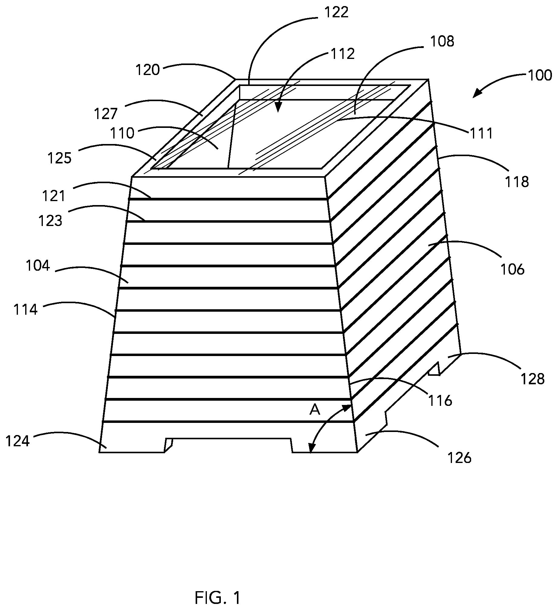
[0033] FIGS. 1-3 illustrate a reusable container 100 having a bottom surface 102, providing a base, and four side walls 104, 106, 108 and 110, connected to one another and extending substantially upwardly from the bottom surface 102 forming a substantially enclosed interior space 112. Each of the sidewalls 104, 106, 108 and 110 are formed in an inverted tapered shape having a greater width immediately adjacent to the bottom surface 102, with width tapering as the side walls 104, 106, 108, and 110 extend upwardly from the bottom surface 102.
[0034] Due to the tapered shape of each of the sidewalls 104, 106, 108, and 110, the container 100 has a distinctly pyramid shape having four corners 114, 116, 118 and 120, formed by corresponding, immediately adjacent sidewalls, 104, 106, 108 and 110. Each corner 114, 116, 118 and 120 is tapered such that each corner forms an angle A with the bottom surface 102 that is less than 90 degrees. For example, the angle formed by each corner 114, 116, 118 and 120 can be 1-5 degrees less than 90 degrees, or another desired angle that is less than 90 degrees.
[0035] The container 100 also includes an opening 122 having a substantially square shape, formed by the sidewalls 104, 106, 108 and 110, although alternative desired shapes can be used. The opening 122 enables a user to access the interior space 112 in order to store desired goods. The opening 122 may be closed by the use of a lid, to be described in more detail below, or a semi-permeable membrane that can regulate the passable of oxygen, carbon dioxide and water vapor between the interior space 112 of the container 100 and the external environment surrounding the container 100, thus creating a modified atmosphere within the container 100. This modified atmosphere can be customized for specific produce or goods through the selection of the lidding material or by semi-permeable patches that may be formed or disposed on the container and/or the lidding materials.
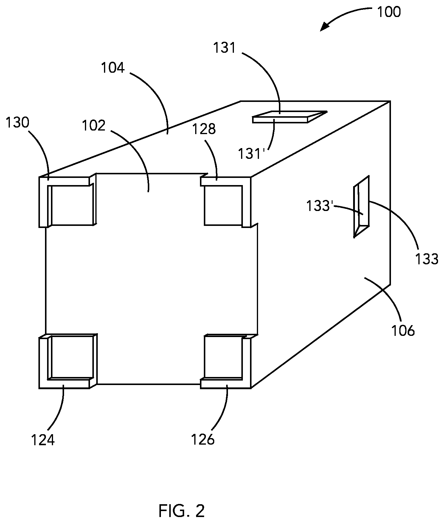
[0036] While the container 100 is further described herein below for use in conjunction with a lid, it is also contemplated that the opening 122 of the container 100 may be sealed with a cover comprising a sheet 111 of a semipermeable membrane or material that is sealed to the top surface of the lip 125 around the perimeter of the opening 122 and extends over the opening 122. The sheet 111 may be transparent so that the contents of the container 100 can be viewed. The sheet is configured to allow flow of water molecules through the material 284 while limiting, thus providing a barrier to, the passage of oxygen and carbon dioxide molecules. Due to the configuration of the feet 124, 126, 128 and 130 (as shown in FIG. 2), the containers 100 can be stacked one on top of the other with the feet 124, 126, 128 and 130 providing lateral stability to the stacked arrangement as will be described in more detail below.
[0037] The bottom surface 102 of the container 100 includes four tabs or feet 124, 126, 128 and 130 that extend downward from surface 102, protruding from the bottom surface 1/4'' to 1/2'' (or another desired distance), at each of the corresponding corners 114, 116, 118 and 120. The tabs 124, 126, 128 and 130 can provide an elevated position for the container 100, enabling air flow to pass beneath the container 100 which can aide in regulating the modified atmosphere within the container 100. The tabs 124, 126, 128 and 130 can be shaped and configured to receive a top surface of a lid of an adjacent container (to be described in more detail below), if multiple containers are stacked on top of each other in a substantially vertical orientation.
[0038] The container 100 can be manufactured as a single unitary structure, using an injection mold process. Alternatively, the container be formed in multiple pieces that can be assembled and secured to one another by fasteners, adhesive or welding, for example. The container 100 can be manufactured from a range of high density plastic material, for example, a range of polyethylene, polypropylene, nylon and nylon blends or other forming materials. The container 100 may also be opaque or transparent, and may be made of any desired color or absent any color. The high compressibility of the injected molded container 100 increases the strength and integrity of the container 100 to resist collapse due to the extended shipping times and, external, lateral and vertical stresses that may occur during transport of the container 100, particularly when multiple containers 100 are stacked on top of each other, which would be typical in the transportation of various goods.
[0039] As shown in FIG. 1, the outer surfaces of the side walls 104, 106, 108 and 110 define a plurality of spaced apart lateral (i.e., horizontally extending) grooves (such as grooves 121 and 123) extending from corner 114 to corner 116, from corner 116 to corner 118 and from corner 118 to corner 120. Each groove, such as grooves 121 and 123 circumscribe the perimeter of the container 100 as they each extend from corner 114 to corner 116, from corner 116 to corner 118 and from corner 118 to corner 120. The grooves, such as grooves 121 and 123 are evenly spaced along the height of the container 100 from proximate the top lip 125 to proximate the top of the feet 124, 126, 128 and 130. The plurality of grooves, such as grooves 121 and 123 provide lateral or horizontally extending channels through which air can circulate and encourages directional air flow around the containers 100. In addition, the grooves 121 and 123 could be replaced with a plurality of raised ribs with corresponding channels formed between the ribs to provide a similar air flow effect. This is particularly beneficial when a plurality of containers 100 are stacked and arranged in a side-by-side manner (as shown in FIG. 10).
[0040] The top lip 125 circumscribes and defines the top surface 127 of the container 100. The lip 125 has a thickness that is wider than the thickness of the side walls 104, 106, 108 and 110. As a result, the lip 125 strengthens the top of the container 100 to prevent the top edges of side walls 104, 106, 108 and 110 from collapsing or bending when the containers 100 are stacked one upon another.
[0041] As shown in FIG. 2, an added feature to the container 100 may be a plurality of handles (two handles 131 and 133 of which are visible), with one handle 131 provided in side wall 104 and one handle 133 provided in side wall 106. Similarly configured handles may also be provided in side walls 108 and 110. The handles may be comprised of protrusions or recesses formed in the side walls. For example, handle 131 is formed from an angled protrusion formed on the outer surfaces of the side wall 104, thus providing a respective protruding gripping surface 131'. Similarly, handles may be formed as recesses, such as handle 133 in the side wall 106. Handle 133 is formed from an angled recess formed in the outer surfaces of the side wall 106, thus providing a respective recessed gripping surface 133'.
[0042] As further shown in FIG. 2, each of the feet 124, 126, 128 and 130 are comprised of first raised surfaces 124', 126', 128' and 130', each having a generally rectangular shape and raised above the bottom surface 102 of the container 100. Each of the feet 124, 126, 128 and 130 are also comprised of second raised surfaces 124'', 126'', 128'' and 130'', each having a generally L-shaped configuration and raised above a respective top surface of the first raised surfaces 124', 126', 128' and 130'. The second raised surfaces 124'', 126'', 128'' and 130'' have outer surfaces that are coextensive with the outer surfaces of the side walls 104, 106, 108 and 110. The inner surfaces of the second raised surfaces 124'', 126'', 128'' and 130'' provide abutment surfaces for engaging with outer surfaces of the top of the lid that is attached to the top of the container 100 as shown and described in more detail herein. That is, the second raised surfaces 124'', 126'', 128'' and 130'' of the feet 124, 126, 128 and 130 overlap the outer surfaces of the top of the lid to secure the container in lateral arrangement with a lid of an adjacent container when stacked on upon the other. The first raised surfaces 124', 126', 128' and 130' then space the top surface of the lid from the bottom surface 102 of the container 100 to allow for air to circulate between stacked containers 100.
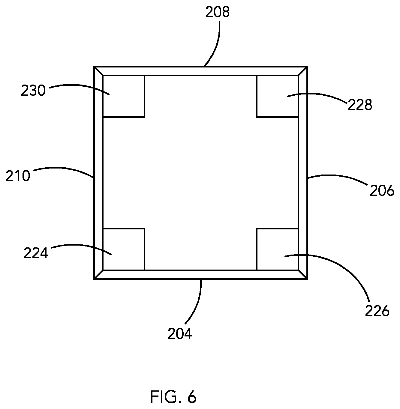
[0043] FIGS. 4-6 illustrate a lid 200, having a top surface 202 and four side walls 204, 206, 208 and 210, connected to one another and extending substantially downwardly from the top surface 202 forming a substantially enclosed interior space to receive the container 100, although alternative shapes and number of sidewalls can also be used if desired. Each of the sidewalls 204, 206, 208 and 210 are formed in a tapered shape having a narrower width immediately adjacent to the top surface 202, with the width tapering as the side walls 104, 106, 108, and 110 extend downwardly from the top surface 202.
[0044] The lid 200, similar to the container 100, has a distinctly pyramid shape having four corners 214, 216, 218 and 220, formed by corresponding, immediately adjacent sidewalls, 204, 206, 208 and 210. Each corner 214, 216, 218 and 220 is tapered such that each corner forms an angle B with the top surface 202 that is greater than 90 degrees. For example, the angle formed by each corner 214, 216, 218 and 220 can be 1-5 degrees greater than 90 degrees, or another desired angle that is less than 90 degrees.
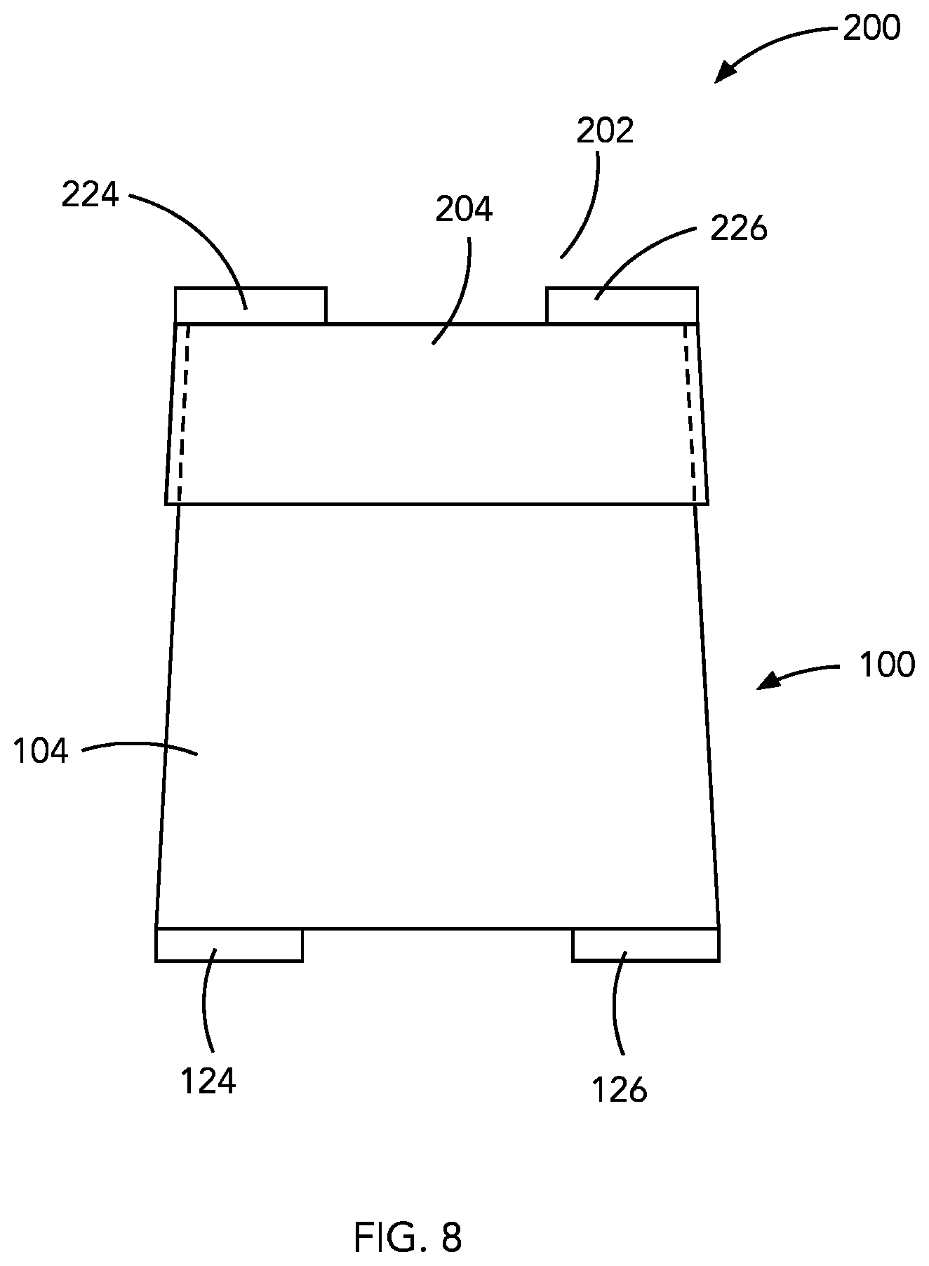
[0045] As shown in FIGS. 7-9, the tapered shape of each of the sidewalls 204, 206, 208, and 210, corresponds to the tapered sidewalls 104, 106, 108 and 110 or the container, enabling the lid 200 to receive the container 100, cover the opening 112, and form a hermetic seal between the container 100 and the lid 200.
[0046] The top surface 202 of the lid 200 includes four raised corners 224, 226, 228 and 230 that extend upwardly from the top surface 202, protruding from the top surface 1/4'' to 1/2'' (or another desired distance), at each of the corresponding corners 214, 216, 218 and 220. The raised corners 224, 226, 228 and 230 can provide separation between containers that are stacked on top of one another in a substantially vertical manner. This separation enables laminar cool air flow to pass between stacked containers 100 which can aide in cooling the goods within the container 100 by circulating air around the four tapered sidewalls 104, 106, 108, and 110, serving as a type of heat exchanging system.
[0047] The lid 200, as with the container 100, can be manufactured as a single unitary structure, using an injection mold process. Alternatively, the lid 200 be formed in multiple pieces that can be assembled and secured to one another by fasteners, adhesive or welding, for example. The lid 200 can be manufactured from a range of high density plastic material, for example, a range of polyethylene, polypropylene, nylon and nylon blends or other forming materials. The lid 200 may also be opaque or transparent, and may be made of any desired color or absent any color. The high compressibility of the injected molded lid 200 increases the strength and integrity of the lid 200 to resist damage due to the extended shipping times and, external, lateral and vertical stresses that may occur during transport of the container 100 and lid 200, particularly when multiple containers 100 are stacked on top of each other, which would be typical in the transportation of various goods.
[0048] As shown in FIGS. 3 and 9, the raised corners 224, 226, 228 and 230 can be shaped and configured to be received within the corresponding feet 124, 126, 128 and 130 of the bottom surface 102 of a container 100 that is stacked on top of the lid 200, in a situation where multiple containers are stacked on top of each other in a substantially vertical orientation. This relative positioning of the raised corners and tabs relative to other containers above and below, forms a solid stacking configuration on, for example, a pallet during transport, with or without support strapping, or during storage at a fixed location. Additionally, as shown in FIG. 9, the interlocking engagement of the raised corners and the feet of adjacent containers ensures that vertically stacked containers maintain a strictly centered orientation on top of one another, such that the structural stresses imposed by the stacked containers are evenly distributed over the entire container and lid components, reducing the likelihood of structural failure, and increases the load bearing strength of the stacked containers, both individually and collectively. Additionally, the engagement of the raised corners and the feet of adjacent containers reduces or restricts lateral shifting of stacked containers with respect to one another, which has significant benefits during transportation of stacked containers. Finally, the engagement of the raised corners and the feet of adjacent containers provides a defined air gap 250 between the bottom surface 102 of the container 100 and the top surface 202 of the lid 200. The air gap 250 may have a height between the bottom surface 102 of the container 100 and the top surface 202 of the lid 200 of between % inch to 1 inch or more,
[0049] As further illustrated in FIG. 10, when the containers 100 and associated lids 200 are arranged in a stacked and side-by-side arrangement, not only can air circulate between the top of the lid 200 and bottom of a container 100 stacked thereon, but because of the tapered side walls 104, 106, 108 and 110 of the containers 100, air gaps 252 are formed between adjacent, side-by-side containers 100 to allow air to circulate around the containers. This increased air flow around the containers helps to improve the circulation and air flow through the gaps 250 formed between stacked containers 100. The air gaps 252 may have a width of between 1/4 to 1/2 inch to 1 inch or more and, as shown may vary in width along the height of the containers 100 and associated lids 200.
[0050] Referring again to FIGS. 4 and 5, the presence of an air gap (as discussed with reference to FIGS. 9 and 10, between the bottom of the container and an adjacent lid when stacked, is important for preserving fresh fruit, vegetables or flowers that may be contained in the container 100 for transport. As shown in FIG. 4, the top surface 202 of the lid 200 defines a recess 260 positioned between the raised surfaces 224, 226, 228 and 230. The recess 260 may be rectangular in shape and includes a bottom surface 262 supported by a plurality of side walls 264, 266, 268 and 270. The bottom surface 262 includes a plurality of holes 272, 274, 276 and 278 that are in fluid communication with the inside of the lid 200. As shown in FIG. 5, the recess 260 is configured to retain a sachet 280 that may be filled with an antimicrobial substance or composition. The holes 272, 274, 276 and 278 are of sufficient size (e.g., 1/2 inch) to allow passage of the antimicrobial substance or composition into the container 100. The holes 272, 274, 276 and 278 may vary in size and number. The sachet 280 is held within the recess 260 by a material 284 in sheet form comprised of a membrane or other semipermeable material that overlaps the edges of the recess 260 and is sealed to the top surface 202 of the lid 200 around the recess 260. The material 284 may form a product label and include images, printed information or various product information regarding the contents of the associated container 100. The material 284 is configured to allow flow of water molecules through the material 284 while limiting, thus providing a barrier to the passage of oxygen and carbon dioxide molecules. As a result, the contents of the container 100 are exposed to the antimicrobial substances contained in the sachet in a relatively closed environment between the sheet material 284 and the inside of the container 100 while allowing water vapor to pass through the material 284 to increase the shelf life of the product contained therein.
[0051] Moreover, the use of various plastic materials, such as injection molded plastic materials, to form the container 100 and lid 200 allows the containers 100 and lids 200 to be washed and reused. That is, conventional containers for fresh produce, fresh vegetables and fresh cut flowers are typically formed from cardboard materials or thin vacuum formed plastic materials that are not generally reusable in any significant or meaningful manner. The result is a large portion of such containers end up in landfills after a single use. By allowing the present containers and lids to be reusable, significant impact on the need for disposal of such containers and lids can be significantly reduced. There is thus disclosed an improved reusable container and method of assembling the reusable container. In the foregoing specification, the present invention has been described with reference to specific exemplary embodiments. Various modifications and changes may be made, however, without departing from the spirit and scope of the present invention as set forth in the claims, including combinations of elements of the various illustrated embodiments. The specification and figures are illustrative, not restrictive, and modifications are intended to be included within the scope of the present invention. Accordingly, the scope of the present invention should be determined by the claims and their legal equivalents rather than by merely the examples described.
[0052] For example, the steps recited in any method or process claims may be executed in any order and are not limited to the specific order presented in the claims. Additionally, the components and/or elements recited in any apparatus claims may be assembled or otherwise operationally configured in a variety of permutations and are accordingly not limited to the specific configuration recited in the claims.
[0053] Benefits, other advantages, and solutions to problems have been described above with regard to particular embodiments. Any benefit, advantage, solution to problem, or any element that may cause any particular benefit, advantage, or solution to occur or to become more pronounced are not to be construed as critical, required, or essential features or components of any or all the claims.
[0054] The phrase "consisting essentially of" as used herein is intended to cover additional elements or functions that do not materially affect the basic and novel characteristics of the claimed invention. Thus, "consisting essentially of" is intended to encompass not only those components specifically listed, but also separate or additional components that do not materially alter the specifically recited functions or elements.
[0055] The terms "comprise", "comprises", "comprising", "having", "including", "includes" or any variations of such terms, are intended to reference a non-exclusive inclusion, such that a process, method, article, composition or apparatus that comprises a list of elements does not include only those elements recited, but may also include other elements not expressly listed or inherent to such process, method, article, composition or apparatus. Other combinations and/or modifications of the above-described structures, arrangements, applications, proportions, elements, materials, or components used in the practice of the present invention, in addition to those not specifically recited, may be varied or otherwise particularly adapted to specific environments, manufacturing specifications, design parameters, or other operating requirements without departing from the general principles of the same.
* * * * *
D00000
D00001
D00002
D00003
D00004
D00005
D00006
D00007
D00008
D00009
XML
uspto.report is an independent third-party trademark research tool that is not affiliated, endorsed, or sponsored by the United States Patent and Trademark Office (USPTO) or any other governmental organization. The information provided by uspto.report is based on publicly available data at the time of writing and is intended for informational purposes only.
While we strive to provide accurate and up-to-date information, we do not guarantee the accuracy, completeness, reliability, or suitability of the information displayed on this site. The use of this site is at your own risk. Any reliance you place on such information is therefore strictly at your own risk.
All official trademark data, including owner information, should be verified by visiting the official USPTO website at www.uspto.gov. This site is not intended to replace professional legal advice and should not be used as a substitute for consulting with a legal professional who is knowledgeable about trademark law.