Method For Detecting The Presence Of Hands On The Steering Wheel
Farshizadeh; Emad ; et al.
U.S. patent application number 16/608496 was filed with the patent office on 2020-05-07 for method for detecting the presence of hands on the steering wheel. This patent application is currently assigned to TRW Automotive GmbH. The applicant listed for this patent is TRW Automotive GmbH. Invention is credited to Emad Farshizadeh, Amo Luengen.
| Application Number | 20200140007 16/608496 |
| Document ID | / |
| Family ID | 62152551 |
| Filed Date | 2020-05-07 |


| United States Patent Application | 20200140007 |
| Kind Code | A1 |
| Farshizadeh; Emad ; et al. | May 7, 2020 |
METHOD FOR DETECTING THE PRESENCE OF HANDS ON THE STEERING WHEEL
Abstract
A method for detecting the presence of a drivers hands on the steering wheel of a motor vehicle is described. By means of a mathematical model, at least one part of a steering system of the motor vehicle is modeled. In addition, a rotational angle of a lower end and/or an upper end of a torsion bar of the steering system is determined. A torque acting on the torsion bar is determined by means of a measuring device and a total torque acting on the steering wheel and a rotational angle acceleration of the steering wheel are estimated by means of a Kalman Filter.
| Inventors: | Farshizadeh; Emad; (Dusseldorf, DE) ; Luengen; Amo; (Koln, DE) | ||||||||||
| Applicant: |
|
||||||||||
|---|---|---|---|---|---|---|---|---|---|---|---|
| Assignee: | TRW Automotive GmbH Alfdorf DE |
||||||||||
| Family ID: | 62152551 | ||||||||||
| Appl. No.: | 16/608496 | ||||||||||
| Filed: | May 8, 2018 | ||||||||||
| PCT Filed: | May 8, 2018 | ||||||||||
| PCT NO: | PCT/EP2018/061885 | ||||||||||
| 371 Date: | October 25, 2019 |
| Current U.S. Class: | 1/1 |
| Current CPC Class: | B62D 1/286 20130101; B62D 15/025 20130101; B62D 6/08 20130101 |
| International Class: | B62D 6/08 20060101 B62D006/08 |
Foreign Application Data
| Date | Code | Application Number |
|---|---|---|
| May 15, 2017 | DE | 10 2017 110 548.4 |
Claims
1. A method for detecting the presence of a driver's hands on the steering wheel of a motor vehicle, in particular a motor vehicle with an electromechanically assisted steering system, comprising the following steps: by means of a mathematical model, at least one part of a steering system of the motor vehicle is modeled, a rotation angle of a lower end and/or an upper end of a torsion bar of the steering system is determined, a torque acting on the torsion bar is determined by means of a measuring device, a total torque acting on the steering wheel and a rotational angle acceleration of the steering wheel are estimated by means of a Kalman Filter, the estimated total torque acting on the steering wheel and the estimated rotational angle acceleration are used to determine a moment of inertia of the steering wheel, and the determined moment of inertia of the steering wheel and a predetermined nominal value of the moment of inertia of the steering wheel are used to determine whether the driver's hands are on the steering wheel.
2. The method according to claim 1, wherein by means of the mathematical model the entire steering system is modeled.
3. The method according to claim 1, wherein by means of the mathematical model an upper part of the steering system of the motor vehicle is modeled, which comprises a steering wheel , a steering column with the torsion bar and the measuring device.
4. The method according to claim 1, wherein by means of a mathematical model a part of the steering above the torsion bar is modeled, said part comprising the steering wheel.
5. The method according to claim 1, wherein an observer is designed on the basis of the mathematical model, which determines the required non-measured variables and the required non-measurable variables.
6. The method according to claim 1, wherein the determined moment of inertia of the steering wheel and the predetermined nominal value of the moment of inertia of the steering wheel are compared to determine whether the driver's hands are on the steering wheel.
7. The method according to claim 6, wherein the moments of inertia are compared by calculating the difference of the two moments of inertia.
8. The method according to claim 1, wherein a state of the steering wheel is modeled by means of a linear state-space model.
9. The method according to claim 1, wherein the measuring device determines the torque acting on the torsion bar from a relative angle between an upper end and the lower end of the torsion bar.
10. The method according to claim 1, wherein the moment of inertia of the steering wheel is determined from a differential equation that describes the relationship between the moment of inertia of the steering wheel, the rotational angle acceleration of the steering wheel and the estimated total torque acting on the steering wheel.
Description
CROSS-REFERENCE TO RELATED APPLICATION
[0001] This application is a national stage of International Application No. PCT/EP2018/061885, filed May 18, 2018, the disclosure of which is incorporated herein by reference in as entirety, and which claimed priority to German Patent Application No. 102017110548.4, filed May 15, 2017, the disclosure of which is incorporated herein by reference in its entirety.
TECHNICAL FIELD
[0002] The invention relates to a method for detecting the presence of a driver's hands on the steering wheel of a motor vehicle, in particular a motor vehicle with an electromechanically assisted steering system.
BACKGROUND
[0003] In motor vehicles with an electromechanically assisted steering system, the electromechanical steering assistance can act on the steering system with a torque, and in this way, assist the driver while driving or steering the vehicle in a certain direction. In particular, the electromechanical steering assistance can steer the vehicle automatically, i.e. without a corresponding steering movement by the driver in a certain direction, for example, based on data from a camera or other sensors. The automatic steering of motor vehicles is used in particular in control systems, at least partially in motor vehicles that move autonomously.
[0004] An example of such a control system are the so-called lane keeping assistance systems, which help the driver to maintain a lane. However, the driver of the motor vehicle should be able to take full control of the motor vehicle again at any time. The presence of the driver's hands on the steering wheel has proved to be a reliable indicator for this purpose.
[0005] In the case of fully autonomous motor vehicles, the control system should automatically control the motor vehicle as long as the driver does not want to take control of the motor vehicle himself. When the driver puts his hands on the steering wheel, this is a clear indicator that he wants to take control of the vehicle. On the contrary, if the driver takes his hands off the steering wheel, the automatic control system should take control of the motor vehicle.
[0006] Therefore, it is necessary in both cases to be able to detect the presence of the driver's hands on the steering wheel. One way to detect the presence of hands on the steering wheel are additional sensors on the steering wheel. The sensors detect, for example, via capacitance measurement whether the hands are on the steering wheel. However, additional sensors generate additional costs.
[0007] Therefore, the object of the invention is to provide a method for detecting the presence of hands on the steering wheel, in which no additional sensors are necessary with respect to existing torque sensors and/or angle sensors included in the electromechanically assisted steering system.
SUMMARY
[0008] The object is achieved according to the invention via a method of the aforementioned type comprising the following steps:
[0009] by means of a mathematical model, at least one part of a steering system of the motor vehicle is modeled,
[0010] a rotation angle of a lower end and/or an upper end of a torsion bar of the steering system is determined,
[0011] a torque acting on the torsion bar is determined by means of a measuring device,
[0012] the total torque acting on the steering wheel and a rotational angle acceleration of the steering wheel are estimated by means of a Kalman Filter,
[0013] the estimated total torque acting on the steering wheel and the estimated rotational angle acceleration are used to determine a moment of inertia of the steering wheel, and
[0014] the determined moment of inertia of the steering wheel and a predetermined nominal value of the moment of inertia of the steering wheel are used to determine whether the driver's hands are on the steering wheel.
[0015] Since the determined moment of inertia of the steering wheel differs from the predetermined nominal value when the driver's hands are on the steering wheel, it is possible to determine whether the drives hands are on the steering wheel. The method according to the invention uses only the already existing sensors in the steering system to detect the presence of the driver's hands on the steering wheel, in particular a torque sensor that determines at least the torque acting on the torsion bar. No additional sensors are required, which saves costs.
[0016] According to one aspect of the invention, the entire steering system is modeled by means of the mathematical model. In particular, both an upper part of the steering system of the motor vehicle comprising a steering wheel, a steering column with the torsion bar and the measuring device, and also a lower part of the steering system of the motor vehicle are modeled.
[0017] According to another aspect, by means of the mathematical model an upper part of the steering system of the motor vehicle is modeled, which comprises a steering wheel, a steering column with the torsion bar and the measuring device.
[0018] A further aspect provides that by means of a mathematical model a part of the steering above the torsion bar is modeled, said part comprising the steering wheel.
[0019] Preferably, an observer is designed on the basis of the mathematical model, which determines the required non-measured variables and the required non-measurable variables. By "observer" is to be understood an observer in the sense of control technology. The observer determines variables that are needed to determine the moment of inertia of the steering wheel, but said variables are not measured or can not be measured. The rotation angle of the lower end of the torsion bar can be determined, more specifically, it can be measured by an angular position sensor of an auxiliary motor of the electromechanically assisted steering system.
[0020] Preferably, the determined moment of inertia of the steering wheel and the predetermined nominal value of the moment of inertia of the steering wheel are compared to determine whether the driver's hands are on the steering wheel. In particular, it is detected that the driver's hands are on the steering wheel when the moments of inertia differ by more than a predetermined value. This predetermined value may be selected in a manner that a recognition error rate is less than 10%, preferably less than 5%, more preferably 0%. In this way, it can be detected with the necessary accuracy, whether the drivers hands are on the steering wheel.
[0021] More preferably, the moments of inertia are compared by calculating the difference between the two moments of inertia. In particular, it is detected that the driver's hands are on the steering wheel when the difference between the moments of inertia differs by more than a predetermined value of zero. This predetermined value may be selected in a manner that a recognition error rate is less than 10%, preferably less than 5%, more preferably 0%. In this way, it can be detected with the necessary accuracy, whether the driver's hands are on the steering wheel.
[0022] According to one aspect of the invention, a state of the steering wheel is modeled by a linear state-space model. In particular, the linear state-space model provides the basis for the design of an observer. By "observer" is to be understood an observer in the sense of control technology. The observer determines variables that are needed to determine the moment of inertia of the steering wheel, but said variables are not measured or cannot be measured.
[0023] According to a further aspect of the invention, the measuring device determines the torque acting on the torsion bar from a relative angle between an upper end and the lower end of the torsion bar. Since the torque acting on the torsion bar is measured anyway, especially in electromechanically assisted steering systems, already existing sensors of the steering system can be used. Therefore, no further components are necessary, resulting in cost savings.
[0024] Preferably, the moment of inertia of the steering wheel is determined from a differential equation that describes the relationship between the moment of inertia of the steering wheel, the rotational angle acceleration of the steering wheel and the estimated total torque acting on the steering wheel. Since the Kalman Filter estimates all the necessary variables, the moment of inertia of the steering wheel in this embodiment of the invention can be easily determined.
[0025] One aspect of the invention additionally provides that a rotational angle of the steering wheel is determined, more specifically, it is measured. In particular, a rotation angle of the upper end of the torsion bar is determined or measured, and equated with the rotation angle of the steering wheel. The rotation angle of the steering wheel in this embodiment of the invention, therefore, must not only be reconstructed by the Kalman Filter, but also must be immediately available in particular as a measured variable.
[0026] More specifically, the measuring device measures the rotation angle of the lower end and/or the upper end of the torsion bar. If the measuring device measures only one of the two rotation angles, the other rotation angle can be reconstructed from the measured rotation angle and from the determined torque acting on the torsion bar. In particular, the rotation angle of the upper end of the torsion bar can be equated with the rotation angle of the steering wheel. In this embodiment of the invention, no additional measuring device is necessary for measuring the rotation angle, resulting in a simpler construction of the steering system.
[0027] In accordance with one embodiment of the invention it is provided that the upper part of the steering system is modeled as a mass with a spring and/or damping element in the mathematical model. By appropriate tuning of model parameters, in particular of spring and damping coefficients, the upper part of the steering system can be modeled as realistically as possible.
[0028] According to another embodiment of the invention, the modeled part of the steering system is modeled as a mass in the mathematical model. This is particularly advantageous when the rotation angle of the upper end of the torsion bar is measured. The simplified model of the upper steering system is then sufficient to determine with enough precision the torque acting on the steering wheel. The calculation effort is reduced in this embodiment of the invention.
BRIEF DESCRIPTION OF THE FIGURES
[0029] Further advantages and features of the invention will become apparent from the following description and the drawings to which reference is made. In which are shown:
[0030] FIG. 1 shows a perspective view of a steering system of a motor vehicle;
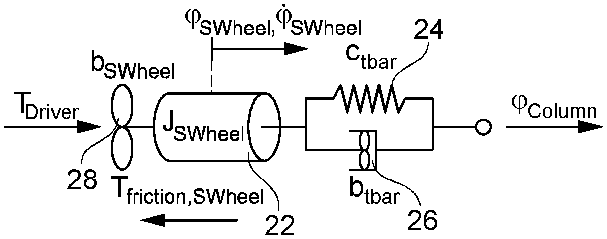
[0031] FIG. 2 shows a physical analogous model of an upper part of the steering system of FIG. 1;
[0032] FIG. 3 shows a simplified physical model of the upper part of the steering system of FIG. 1; and
[0033] FIG. 4 shows a schematic representation of the steps of the method according to the invention.
DETAILED DESCRIPTION
[0034] A steering system 10 shown in FIG. 1 of a motor vehicle is designed as an electromechanically assisted steering system. The steering system 10 comprises an upper part 12 with a steering wheel 14, a steering column 16 with a torsion bar 17, and a measuring device 18 and a lower portion with an auxiliary motor 20.
[0035] The driver acts on the steering wheel 14 with a torque, so that the steering column 16 is rotated. The measuring device 18 determines a torque acting on the torsion bar 17 from a relative angle between an upper (laterally to the steering wheel) end and a lower end of the torsion bar 17. In addition, an angular position sensor of the auxiliary motor 20 determines a rotation angle of the lower end of the torsion bar 17.
[0036] Based on the determined torque acting on the torsion bar 17 and on the rotation angle of the lower end of the torsion bar 17, the auxiliary motor 20 is controlled in a manner that it provides a suitable supporting torque for steering the vehicle.
[0037] In at least partially autonomous motor vehicles, it is necessary that the motor vehicle can detect whether the driver's hands are on the steering wheel 14. In the method described below, only measured variables are used, which were already measured by the measuring device 18 and the angular position sensor of the auxiliary motor 20 of the steering system 10, more precisely, the rotation angle of the lower end of the torsion bar 17 and the torque acting on the torsion bar 17.
[0038] The upper part 12 of the steering system 10 is first modeled according to the physical analogous model shown in FIG. 2. In this model, a system comprising the steering wheel 14, the steering column 16 with the torsion bar 17, and the measuring device 18 is modeled by a mass 22 with a moment of inertia J.sub.SWheel, a spring 24 with a spring coefficient c.sub.tbar and a damping material 26 with a damping coefficient b.sub.tbar. In this case, the spring 24 and the material damping 26 are modeling the torsion bar 17.
[0039] In addition, it is factored that via a damping element 28 with damping coefficient b.sub.SWheel, the torque T.sub.Driver with which the driver acts on the steering wheel 14 is damped by viscous friction, in particular by bearing friction on the steering wheel 14. A total induced counter-torque T.sub.friction in the upper part 12 of the steering system 10 counteracts the torque T.sub.Driver by means of Coulomb friction.
[0040] Equations can be deduced from the physical analogous model, which constitute a mathematical model of the upper part 12 of the steering system 10. This is explained in more detail below.
[0041] A state of the steering wheel 14 is then modeled with a linear state-space model. By "state" is to be understood a minimum set of variables {right arrow over (x)}, which are required to describe the system. Here, the state of the steering wheel 14 is observed. The relevant state variables are the rotation angle .phi..sub.SWheel and the rotation angle speed .phi..sub.SWheel of the steering wheel 14. Then, in particular, the formula is:
x .fwdarw. = ( .PHI. SWheel .PHI. . SWheel ) . ##EQU00001##
[0042] The fact that the state is dependent upon time is not explicitly shown below, but assumed implicitly. The time development of the state of the steering wheel 14 is given by the following equation:
x .fwdarw. . = A x .fwdarw. + B u .fwdarw. = A ( .PHI. SWheel .PHI. . SWheel ) + B ( u control u dist ) . ##EQU00002##
[0043] This equation represents a differential equation or a difference equation, depending on whether a continuous time evolution or a discrete time evolution is observed. Here u.sub.control=.phi..sub.column represents in this embodiment the determined (known) rotation angle of the angle position sensor of the lower end of the torsion bar 17. Also, u.sub.dist=T.sub.Driver+T.sub.friction represents the (unknown) sum of the torque with which the driver acts on the steering wheel 14, and the counter-torque due to the Coulomb friction.
[0044] u.sub.dist describes an unknown disturbance of the state, occurring in the upper part 12 of the steering system 10. The matrices A and B describe the development of the state {right arrow over (x)} and are dependent upon the parameters of the mathematical model.
[0045] As already mentioned, the measuring device 18 determines the torque acting on the torsion bar 17 from the relative angle between the upper end and the lower end of the torsion bar 17, which is referred to below with T.sub.tbar. The measured torque T.sub.tbar is related to the state of the steering wheel 14 via the following equation:
T.sub.tbarC {right arrow over (x)}+D {right arrow over (u)}.
[0046] Here, the matrices C and D describe the relation between the current state {right arrow over (x)} of the steering wheel 14, the partly known and partly unknown input variables II and the measured torque T.sub.tbar. Together with the above equation for the time evolution of the state of the steering wheel 14, the equation T.sub.tbar=C {right arrow over (x)}+D {right arrow over (u)} forms a linear state space model for the state of the steering wheel.
[0047] From the measurement of the rotation angle of the lower part of the torsion bar 17 and from the torque acting on the torsion bar 17, u.sub.dist can not be extrapolated directly to the state of the steering wheel 14 and the disturbance variable. Rather, the state of the steering wheel 14 and the disturbance variable u.sub.dist must be estimated.
[0048] For this purpose, a Kalman Filter is used. Based on the measured variables and the selected mathematical model, this filter estimates the state of the steering wheel 14 and unknown input variables. More specifically, the Kalman Filter estimates the rotation angle .phi..sub.SWheel the steering wheel 14, the rotation angle speed .phi..sub.SWheel of the steering wheel 14 and the disturbance T.sub.Driver+T.sub.friction acting on the upper part 12 of the steering system 10. Furthermore, the rotational angle acceleration {umlaut over (.phi.)}.sub.SWheel of the steering wheel 14 is estimated. In addition, the counter-torque induced by viscous friction can be calculated according to T.sub.bSWheel=b.sub.SWheel .phi..sub.SWheel and by the estimation of .phi..sub.SWheel by knowing the damping coefficient b.sub.SWheel.
[0049] The movement equation for the part of the steering system 10 above the torsion bar 17 with a cumulated moment of inertia J.sub.SWheel is:
J.sub.SWheel{umlaut over (.phi.)}.sub.SWheel=T.sub.Driver+T.sub.friction-T.sub.tbar-T.sub.bSWheel
[0050] Below, for the sake of simplicity the part of the steering system 10 above the torsion bar 17 is referred to as the steering wheel 14. In addition, in the context of the model it is assumed that the rotation angle of the upper end of the torsion bar 17 coincides with the rotation angle of the steering wheel 14.
[0051] The movement equation can be solved in accordance with the moment of inertia J.sub.SWheel of the steering wheel 14. This means:
J.sub.SWheel-1/{umlaut over (.phi.)}.sub.SWheel(T.sub.Driver+T.sub.friction-T.sub.tbar-T.sub.bSWheel)
[0052] Via the Kalman Filter, all additionally required variables are estimated, which are necessary to calculate the moment of inertia J.sub.SWheel of the steering wheel 14. More precisely, all the variables to calculate the moment of inertia of the steering wheel 14 are estimated, including all the required non-measured variables and all the required non-measurable variables.
[0053] In the embodiment discussed here, the torque T.sub.tbar acting on the torsion bar 17 is measured by the measuring device 18. However, the torque acting on the torsion bar 17 can also alternatively be estimated by the Kalman Filter.
[0054] The calculated moment of inertia J.sub.SWheel of the steering wheel 14 is now compared with a predetermined nominal value of the moment of inertia J.sub.SWheel,nom of the steering wheel 14, in particular by calculating the difference between the two moments of inertia.
[0055] The moment of inertia of the steering wheel 14 differs from the predetermined nominal value of the moment of inertia, when the hands (or one hand) of the driver are on the steering wheel 14. Accordingly, it is detected that the hands are on the steering wheel 14 when the moment of inertia of the steering wheel 14 differs by more than a predetermined deviation from the nominal value.
[0056] The deviation value may be selected in such a way that a positive error detection rate (it is detected that the hands are on the steering wheel 14, although this is incorrect) and/or a negative error detection rate (it is not detected that the hands are on the steering wheel 14, although this is not the case) is each below 10%, preferably less than 5%, particularly preferably 0%.
[0057] In other words, the method described above is based on an observer in the sense of control technology, as illustrated in FIG. 4. A real system comprising the steering wheel 14, the steering column 16 with the torsion bar 17, and the measuring device 18 is simulated as described above by a mathematical model. This mathematical model serves as the basis for designing the observer. From known input variables and measured variables u.sub.control or y.sub.meas, unknown state variables and input parameters {right arrow over (y)}.sub.obs are estimated by the observer ("upper observer" in FIG. 4) as described above. From this, a parameter J.sub.SWheel is calculated together with the measured variable T.sub.tbar ("Parameter calculation" in FIG. 4) and compared with a nominal value ("comparison with nominal value" in FIG. 4).
[0058] The rotation angle of the steering wheel 14 can alternatively be determined as follows. From the rotation angle determined by the angular position sensor of the lower end of the torsion bar 17, and the measured torque acting on the torsion bar 17, the rotation angle of the upper end of the torsion bar 17 can be reconstructed by solving the equation
T.sub.tbar=c.sub.tbar.DELTA..phi.
according to the rotation angle of the upper end of the torsion bar 17, wherein .DELTA..phi. represents the difference between the rotation angle of the upper end and the lower end of the torsion bar 17. In the context of the model used, the rotation angle of the upper end of the torsion bar 17 can be set equal to the rotation angle of the steering wheel 14. The rotation angle of the steering wheel 14 is then available for further calculations and does not need to be estimated by the Kalman Filter.
[0059] If the measuring device 18 of the steering system 10 is designed in such a way that in addition to the torque acting on the torsion bar 17 it can also measure the rotation angle of the lower end and/or the upper end of the torsion bar 17, then there are several simplifications compared to the method described above.
[0060] If the measuring device 18 measures the rotation angle of the lower end of the torsion bar 17, this rotation angle can be used immediately as described above for the Kalman Filter or to determine the rotation angle of the upper end of the torsion bar. Then, in particular, it is not necessary to determine the rotation angle of the lower end of the torsion bar from a signal of the angular position sensor of the auxiliary motor 20.
[0061] If the measuring device 18 measures the rotation angle of the upper end of the torsion bar 17 (and thus the rotation angle of the steering wheel 14), then this rotation angle is immediately available as a measured variable for further calculations. Therefore, the rotation angle of the steering wheel 14 must in particular not only necessarily be estimated by the Kalman Filter. Similarly, the rotation angles of the upper end and the lower end of the torsion bar 17 are immediately available for further calculations when the measuring device measures these two angles of rotation.
[0062] Hereafter, it is assumed that the measuring device 18 is designed in such a way that it measures at least the rotation angle of the upper end of the torsion bar 17, or that the rotation angle of the upper end of the torsion bar 17 can be determined from the rotation angle of the lower end of the torsion bar.
[0063] The upper part 12 of the steering system 10 can then be modeled by means of a simplified physical analogous model shown in FIG. 3. Compared with the physical analogous model shown in FIG. 2, the spring 24 and the damping material 26 are omitted here. This can simplify determining the torque that is acting on the steering wheel 14 by means of the Kalman filter.
[0064] As described above, the rotation angle of the steering wheel 14 is available as a measured variable and does not need to be estimated only via the Kalman Filter. In this case, the measured variable is the rotation angle of the steering wheel 14, then y.sub.meas=.phi..sub.SWheel. The known input variable is the torque acting on the torsion bar, so it applies u.sub.control=T.sub.tbar. The moment of inertia of the steering wheel 14 can then be determined analogously to the method described above and compared with a nominal value.
[0065] With respect to the remaining features and other steps and advantages of the method, please refer to the above explanations.
* * * * *
D00000
D00001
D00002
XML
uspto.report is an independent third-party trademark research tool that is not affiliated, endorsed, or sponsored by the United States Patent and Trademark Office (USPTO) or any other governmental organization. The information provided by uspto.report is based on publicly available data at the time of writing and is intended for informational purposes only.
While we strive to provide accurate and up-to-date information, we do not guarantee the accuracy, completeness, reliability, or suitability of the information displayed on this site. The use of this site is at your own risk. Any reliance you place on such information is therefore strictly at your own risk.
All official trademark data, including owner information, should be verified by visiting the official USPTO website at www.uspto.gov. This site is not intended to replace professional legal advice and should not be used as a substitute for consulting with a legal professional who is knowledgeable about trademark law.