Methods, Apparatuses And Systems For Additive Manufacturing With Preheat
ARMIJO; Armando ; et al.
U.S. patent application number 16/672025 was filed with the patent office on 2020-05-07 for methods, apparatuses and systems for additive manufacturing with preheat. The applicant listed for this patent is Arevo, Inc.. Invention is credited to Armando ARMIJO, Riley REESE.
| Application Number | 20200139694 16/672025 |
| Document ID | / |
| Family ID | 64014449 |
| Filed Date | 2020-05-07 |


| United States Patent Application | 20200139694 |
| Kind Code | A1 |
| ARMIJO; Armando ; et al. | May 7, 2020 |
METHODS, APPARATUSES AND SYSTEMS FOR ADDITIVE MANUFACTURING WITH PREHEAT
Abstract
The present disclosure provides methods for additive manufacturing of a three-dimensional (3D) object, comprising preheating a feed comprising a polymer material to a temperature in excess of a glass transition temperature and below a melting point of the polymer material. The preheating may occur at a first location in an additive manufacturing apparatus. Next, the polymer material may be melted at a second location that is spatially distinct from the first location.
| Inventors: | ARMIJO; Armando; (Milpitas, CA) ; REESE; Riley; (Milpitas, CA) | ||||||||||
| Applicant: |
|
||||||||||
|---|---|---|---|---|---|---|---|---|---|---|---|
| Family ID: | 64014449 | ||||||||||
| Appl. No.: | 16/672025 | ||||||||||
| Filed: | November 1, 2019 |
Related U.S. Patent Documents
| Application Number | Filing Date | Patent Number | ||
|---|---|---|---|---|
| PCT/US2018/030785 | May 3, 2018 | |||
| 16672025 | ||||
| 15587292 | May 4, 2017 | |||
| PCT/US2018/030785 | ||||
| Current U.S. Class: | 1/1 |
| Current CPC Class: | B29C 2035/0872 20130101; B29C 35/0261 20130101; B29C 2035/0283 20130101; B29C 64/20 20170801; B29B 13/02 20130101; B29C 64/106 20170801; B29C 2035/0838 20130101; B29C 2035/0855 20130101; B33Y 10/00 20141201; B29C 2035/0822 20130101; B29C 2035/046 20130101; B29C 2035/0877 20130101; B29C 64/153 20170801; B33Y 30/00 20141201; B29B 13/08 20130101 |
| International Class: | B33Y 30/00 20060101 B33Y030/00; B33Y 10/00 20060101 B33Y010/00; B29B 13/02 20060101 B29B013/02; B29C 64/153 20060101 B29C064/153; B29C 64/106 20060101 B29C064/106; B29C 64/20 20060101 B29C064/20; B29B 13/08 20060101 B29B013/08 |
Claims
1-26. (canceled)
27. A system for printing at least a portion of a three-dimensional (3D) object, comprising: a source of at least one feedstock that is configured to supply said at least one feedstock for printing said at least said portion of said 3D object, which said at least one feedstock comprises a polymer material; a substrate for supporting said at least said portion of said 3D object during printing; a printing unit that is configured to direct said at least one feedstock from said source of said at least one feedstock towards said substrate; at least one energy source configured to provide energy; and a controller operatively coupled to said printing unit and said at least one energy source, wherein said controller is programmed to direct said at least one energy source to provide said energy to: (i) preheat, at a first location in said printing unit, said at least one feedstock to a preheat temperature in excess of a glass transition temperature and below a melting temperature of said polymer material, to thereby provide a preheated feedstock, and (ii) melt, at a second location that is spatially distinct from said first location, said preheated feedstock to provide a melted feedstock.
28. The system of claim 27, wherein said at least one energy source is selected from the group consisting of a direct contact heater, a hot air blower, and a laser.
29. The system of claim 27, wherein said at least one energy source is a laser configured to provide said energy comprising a first light beam and a second light beam.
30. The system of claim 29, wherein said controller is further programmed, in (i), to direct said at least one energy source to provide said first light beam to preheat said at least one feedstock.
31. The system of claim 29, wherein said controller is further programmed, in (ii), to direct said at least one energy source to provide said second light beam to melt said preheated feedstock.
32. The system of claim 29, further comprising a beam splitter configured to split a light beam from said at least one energy source into said first light beam and said second light beam.
33. The system of claim 29, wherein said first light beam has a different intensity than said second light beam.
34. The system of claim 27, wherein said controller is further programmed, prior to (ii), to use said printing unit to direct said preheated feedstock to said second location.
35. The system of claim 34, wherein said second location is external to said printing unit.
36. The system of claim 27, wherein said preheat temperature is in a range of about 0.7 to 0.95 times the melting temperature of said polymer material.
37. The system of claim 27, wherein said preheat temperature is in a range of about 0.8 to 0.9 times the melting temperature of said polymer material.
38. The system of claim 27, wherein (i) occurs in a first period of time and (ii) occurs in a second period of time, and wherein said first period of time is longer than said second period of time.
39. The system of claim 27, wherein said at least one feedstock is a continuous fiber composite.
40. The system of claim 27, wherein said polymer material comprises a semi-crystalline polymer.
41. The system of claim 27, further comprising a compaction unit configured to compact said at least one feedstock along said substrate.
42. The system of claim 41, wherein said compaction unit comprises a rigid body, one or more idler rollers, at least one freely suspended roller, a coolant unit, or any combination thereof.
43. The system of claim 41, wherein said compaction unit is configured to be positioned along only one side of said melted feedstock.
44. The system of claim 41, wherein said controller is further programmed to direct said compaction unit to compact said melted feedstock.
45. The system of claim 41, wherein said controller is further programmed to direct said compaction unit to cool said melted feedstock.
46. The system of claim 27, further comprising one or more sensors configured to measure one or more feedstock temperatures along said at least one feedstock during printing.
Description
CROSS-REFERENCE
[0001] The present application is a continuation of International Patent Application No. PCT/US18/30785, filed May 3, 2018, which claims priority to U.S. patent application Ser. No. 15/587,292, filed May 4, 2017, which is entirely incorporated herein by reference.
BACKGROUND
[0002] Additive manufacturing is the term given to processes that manufacture objects using sequential-layer material addition/joining throughout a three-dimensional (3D) work envelope under automated control. The International Organization for Standardization/American Society for Testing and Materials 52900-15 (ISO/ASTM52900-15) defines seven categories of additive manufacturing processes: binder jetting, directed energy deposition, material extrusion, material jetting, powder bed fusion, sheet lamination, and vat polymerization.
[0003] Extrusion-based 3D printing processes produce an object by extruding small beads of material, such as thermoplastics, which quickly harden to form a layer. Successive layers of material are deposited to create the object. For material extrusion, two important factors are control over the extruded filament and the rate at which the material can be extruded. Regarding the latter factor, guidelines may be presented in terms of a volume of material that can be printed per second. Given a thickness for the extrudate layer, the print speed may be dictated.
SUMMARY
[0004] In an aspect, the present disclosure provides a method for additive manufacturing of a three-dimensional (3D) object, the method comprising (a) preheating, at a first location in an additive manufacturing apparatus, a feed comprising a polymer material to a temperature in excess of a glass transition temperature and below a melting point of the polymer material; and (b) melting, at a second location that is spatially distinct from the first location, the polymer material. In some embodiments, the temperature is from about 0.7 to about 0.95 times the melting point of the polymer material. In some embodiments, the temperature is from about 0.8 to about 0.9 times the melting point of the polymer material. In some embodiments, the second location is on a build surface on which the 3D object is manufactured. In some embodiments, preheating occurs in a first period of time and melting occurs in a second period of time. In some embodiments, the first period of time is longer than the second period of time. In some embodiments, a rate at which the polymer material is melted is greater than a rate at which the polymer material is preheated. In some embodiments, the feed is in a form of a filament. In some embodiments, the feed is in a form of a powder. In some embodiments, the polymeric material comprises a semi-crystalline polymer. In some embodiments, the polymeric material comprises an amorphous polymer. In some embodiments, the preheating is performed by a first heating device and melting is performed by a second heating device. In some embodiments, the method for additive manufacturing of a 3D object further comprises depositing a portion of the feed comprising the polymer material melted in (b). In some embodiments, the portion of the feed is deposited in accordance with a computer model of the 3D object.
[0005] In some embodiments, the method for additive manufacturing of a 3D object further comprises depositing a portion of the feed preheated in (a) over a build surface, and melting the polymer material in the portion of the feed deposited over the build surface. In some embodiments, the method for additive manufacturing of a 3D object further comprises using an energy source to melt the polymer material. In some embodiments, the energy source is a laser.
[0006] In another aspect, the present disclosure provides an apparatus for additive manufacturing of a three-dimensional (3D) object, comprising a preheater; and an energy source, wherein energy from the energy source melts the polymer material at a second location that is spatially distinct from the first location. In some embodiments, the preheater heats a feed comprising a polymer material to a temperature in excess of a glass transition temperature and below a melting point of the polymer material. In some embodiments, the polymer material is preheated at a first location. In some embodiments, the apparatus for additive manufacturing of the 3D object further comprises a feed subsystem. The feed subsystem may deliver the feed to the first location. In some embodiments, the second location is proximal to a build surface. In some embodiments, the preheater is selected from the group consisting of a direct contact heater, a hot air blower, and a laser. In some embodiments, the energy source is a laser. In some embodiments, the preheater heats the feed to the temperature from about 0.7 to about 0.95 times the melting point of the polymer material. In some embodiments, the preheater heats the polymer material for a first period of time that is longer than a second period of time in which the energy source melts the polymer material. In some embodiments, the apparatus for additive manufacturing of the 3D object further comprises a filament shaper, wherein the filament shaper applies pressure to the feed as it is melted proximal to the build surface. In some embodiments, the apparatus for additive manufacturing of the 3D object further comprises a temperature control system for controlling an amount of heat supplied by the preheater. In some embodiments, the apparatus for additive manufacturing of the 3D object further comprises a controller operative coupled to the preheater and energy source, wherein the controller comprises one or more computer processors that are individually or collectively programmed to (i) direct the preheater to heat the feed comprising the polymer material at the first location, and (ii) direct the energy source to provide the energy to melt the polymer material at the second location.
[0007] The polymeric material used for printing may be preheated prior to being melted. This approach may be used with three-dimensional (3D) printing methodologies. Examples of 3D printing methodologies comprise extrusion, wire, granular, laminated, light polymerization, VAT photopolymerization, material jetting, binder jetting, sheet lamination, directed energy deposition, or power bed and inkjet head 3D printing. Extrusion 3D printing can comprise robo-casting, fused deposition modeling (FDM) or fused filament fabrication (FFF). Wire 3D printing can comprise electron beam freeform fabrication (EBF3). Granular 3D printing can comprise direct metal laser sintering (DMLS), electron beam melting (EBM), selective laser melting (SLM), selective heat sintering (SHS), or selective laser sintering (SLS). Power bed and inkjet head 3D printing can comprise plaster-based 3D printing (PP). Laminated 3D printing can comprise laminated object manufacturing (LOM). Light polymerized 3D printing can comprise stereo-lithography (SLA), digital light processing (DLP) or laminated object manufacturing (LOM). Furthermore, preheating can apply to a filament shaping deposition system and method for 3D printing developed by the inventor(s) and disclosed in U.S. patent application Ser. No. 15/471,786, which is incorporated by reference herein.
[0008] In some instances, the speed at which some 3D printing processes can be operated is limited by the thermal response time of the feedstock. This response time is technically described as the relaxation or reptation time under polymer reptation theory.
[0009] The more quickly the polymer feed to a 3D printer is heated, the more material the printer can process in a given period-of-time. But thermal degradation may occur if a feedstock is heated too quickly. This degradation can involve chain scission (i.e., breaking). The resulting segments can react with one another and change the properties of the feedstock. This can lead to degradation in physical properties in a printed object relative to initially specified properties. Such property changes include reduced ductility and embrittlement, chalking, color changes, cracking, and a general reduction in most other desirable physical properties.
[0010] In some instances, the feedstock may be a polymer. To avoid thermal degradation, a polymer may be given time to "relax" to accommodate the energy it receives. The time it takes for a polymer chain to relax can be unique to each polymer and can be dictated by the "reputation" or relaxation time of the polymer. Reptation is the thermal motion of very long, linear, entangled macromolecules in the polymer melt stage. The reputation time may be the time a polymer chain takes to diffuse out of a virtual tube to which the polymer is considered to be confined. The speed at which a polymer filament can be processed may be limited by reptation.
[0011] In some instances, a heating profile for 3D printing processes comprises raising the temperature of the polymer feed to its melting point in a single step. The temperature increase can occur either immediately before or after deposition, as a function of the 3D printing process. The rate at which the temperature is raised and at which the polymer is processed may be limited by the reptation time. If the polymer feed is preheated to a temperature at or above its glass transition temperature (T.sub.g) while in the 3D printer, and subsequently raised to its melting temperature (either immediately before or after deposition per the specific process), the polymer can be processed more rapidly.
[0012] In some instances, the polymer feed may have a residence time in the 3D printer, and to the extent the feed is preheated during that residence time, there may be no "cost" to the time required for such preheating. There may be a "cost" for the time it takes to melt the feedstock, which occurs at the exit of 3D printer or on the build surface. In other instances when the feed is entering the melting zone at much higher temperature than may otherwise be the case, the melting time may be significantly reduced. In fact, experiments have demonstrated a five- to six-fold increase in the speed at which polyaryletherketones (PEAK) polymer feeds can be processed by virtue of the novel preheating step disclosed herein.
[0013] At the glass transition temperature, the polymer chains may become increasingly mobile and can slide past one another, thereby processing the energy received during heating. Since the polymer feed may be more mobile during the melting step than the preheating step, the polymer can be heated at a greater rate during the melting step. This may further increase the processing time.
[0014] Thus, in accordance with the present disclosure, various 3D printing devices and methods may be improved by preheating the polymer feed to a temperature at or above its glass transition temperature, but below its melting point, prior to melting the polymer for incorporation into the build object.
[0015] In another aspect, the system comprises a filament-shaping deposition system with preheat for additive manufacturing. In some embodiments, preheat may be added to other 3D printing processes, including material extrusion, directed energy deposition, and material jetting processes.
[0016] In an embodiment, a filament-shaping deposition system can include a positioning subsystem, a feed subsystem, an optional preheating subsystem, a focused heat source, and/or a filament shaper.
[0017] In another embodiment, the positioning subsystem may comprise a multi-axis end effector (e.g., a robotic arm, etc.). The multi-axis end effector may have sufficient degrees of freedom (i.e., six DOF) to enable true three-dimensional printing. The positioning subsystem may be capable of delivering a feed filament to an arbitrary location in space, as specified in accordance with the build instructions.
[0018] The feed subsystem may deliver the feedstock to a build surface (e.g., a build plate, etc.). The focused heat source may be used to (a) raise the temperature of the feedstock to its melting point, and (b) melt the previously deposited layer of material just below the feedstock currently being deposited. The focused heat source may be a laser. The filament shaper can apply pressure to the melted filament, thereby controlling its position/location and altering its cross section from circle to flat-rectangular (i.e., ribbon-like). Altering the filament's cross section in the aforementioned fashion may result in improvements in the properties of the printed object.
[0019] The preheating subsystem may be embodied in a variety of ways, which can be different for different 3D printing processes as a function of their varying configurations. Some non-limiting embodiments of the preheating sub-system, for use in context with applicant's filament-shaping deposition method, are discussed below.
[0020] The preheating subsystem may comprise a direct contact heater for the feedstock tube or guide through which the feedstock passes prior to deposition. In some embodiments, the heater, in the form of ribbon, wire or other flexible material, may be wrapped around the exterior of the feed tube below an in-line cutter.
[0021] Alternatively, the preheating subsystem may comprise forced hot air. The hot air may be delivered from a hot air blower. In some instances, slots, which are formed in the feed tube below the in-line cutter, can provide for direct contact between the hot air and the feedstock.
[0022] A laser may be used to preheat the feedstock. In some instances, a laser with sufficient power, dedicated for preheating, may be used. The beam from the laser can be directed at the portion of the feed tube below the in-line cutter. In other instances, the beam from the focused heat source may be split into two beams of unequal intensity. The beam with the lower intensity can be directed to the portion of the feed tube below the in-line cutter for preheating the feedstock. The beam with the higher intensity may be directed to the feedstock and/or the most recently deposited underlying layer.
[0023] Additional aspects and advantages of the present disclosure may become readily apparent to those skilled in this art from the following detailed description, wherein only illustrative embodiments of the present disclosure are shown and described. As will be realized, the present disclosure is capable of other and different embodiments, and its several details are capable of modifications in various obvious respects, all without departing from the disclosure. Accordingly, the drawings and description are to be regarded as illustrative in nature, and not as restrictive.
INCORPORATION BY REFERENCE
[0024] All publications, patents, and patent applications mentioned in this specification are herein incorporated by reference to the same extent as if each individual publication, patent, or patent application was specifically and individually indicated to be incorporated by reference.
BRIEF DESCRIPTION OF THE DRAWINGS
[0025] The novel features of the invention are set forth with particularity in the appended claims. A better understanding of the features and advantages of the present invention will be obtained by reference to the following detailed description that sets forth illustrative embodiments, in which the principles of the invention are utilized, and the accompanying drawings (also "figure" and "FIG." herein), of which:
[0026] FIG. 1 depicts a block diagram of the salient components of a filament-shaping deposition system for additive manufacturing;
[0027] FIG. 2 depicts a first embodiment of the filament-shaping deposition system of FIG. 1;
[0028] FIG. 3 depicts a second embodiment of the filament-shaping deposition system of FIG. 1;
[0029] FIG. 4 depicts a third embodiment of the filament-shaping deposition system of FIG. 1;
[0030] FIG. 5 depicts a fourth embodiment of the filament-shaping deposition system of FIG. 1;
[0031] FIG. 6 depicts a side view of a portion of a material extrusion (fused deposition modeling) 3D printer, in accordance with the present disclosure;
[0032] FIG. 7 depicts a side view of a portion of a directed energy deposition three-dimensional (3D) printer, in accordance with the present disclosure;
[0033] FIG. 8 depicts a method in accordance with an illustrative embodiment of the present system;
[0034] FIG. 9 depicts a method for using a temperature control loop to control a preheating operation;
[0035] FIG. 10 depicts the heating profile of the polymer feed, in accordance with the present disclosure;
[0036] FIGS. 11A-11C depict various embodiments of preheating and melting zones for various 3D printer configurations; and
[0037] FIG. 12 depicts a computer control system that is programmed or otherwise configured to implement methods provided herein.
DETAILED DESCRIPTION
[0038] While various embodiments of the invention have been shown and described herein, it will be obvious to those skilled in the art that such embodiments are provided by way of example only. Numerous variations, changes, and substitutions may occur to those skilled in the art without departing from the invention. It should be understood that various alternatives to the embodiments of the invention described herein may be employed.
[0039] The term "three-dimensional printing" (also "3D printing"), as used herein, generally refers to a process or method for generating a 3D part (or object). For example, 3D printing may refer to sequential addition of material layer or joining of material layers or parts of material layers to form a three-dimensional (3D) part, object, or structure, in a controlled manner (e.g., under automated control). In the 3D printing process, the deposited material can be fused, sintered, melted, bound or otherwise connected to form at least a part of the 3D object. Fusing the material may include melting or sintering the material. Binding can comprise chemical bonding. Chemical bonding can comprise covalent bonding. Examples of 3D printing include additive printing (e.g., layer by layer printing, or additive manufacturing). The 3D printing may further comprise subtractive printing.
[0040] The term "part," as used herein, generally refers to an object. A part may be generated using 3D printing methods and systems of the present disclosure. A part may be a portion of a larger part or object, or an entirety of an object. A part may have various form factors, as may be based on a model of such part. Such form factors may be predetermined.
[0041] The term "composite material," as used herein, generally refers to a material made from two or more constituent materials with different physical or chemical properties that, when combined, produce a material with characteristics different from the individual components.
[0042] The term "fuse", as used herein, generally refers to binding, agglomerating, or polymerizing. Fusing may include melting, softening or sintering. Binding may comprise chemical binding. Chemical binding may include covalent binding. The energy source resulting in fusion may supply energy by a laser, a microwave source, source for resistive heating, an infrared energy (IR) source, a ultraviolet (UV) energy source, hot fluid (e.g., hot air), a chemical reaction, a plasma source, a microwave source, an electromagnetic source, or an electron beam. Resistive heating may be joule heating. A source for resistive heating may be a power supply. The hot fluid can have a temperature greater than 25.degree. C., or greater than or equal to about 40.degree. C., 50.degree. C., 60.degree. C., 70.degree. C., 80.degree. C., 90.degree. C., 100.degree. C., 150.degree. C., 200.degree. C., 250.degree. C., 300.degree. C., 350.degree. C., 400.degree. C., 450.degree. C., 500.degree. C., or higher. The hot fluid may have a temperature that is selected to soften or melt a material used to print an object. The hot fluid may have a temperature that is at or above a melting point or glass transition point of a polymeric material. The hot fluid can be a gas or a liquid. In some examples, the hot fluid is air.
[0043] The term "adjacent" or "adjacent to," as used herein, generally refers to `on,` `over, `next to,` adjoining,` `in contact with,` or `in proximity to.` In some instances, adjacent components are separated from one another by one or more intervening layers. The one or more intervening layers may have a thickness less than about 10 micrometers ("microns"), 1 micron, 500 nanometers ("nm"), 100 nm, 50 nm, 10 nm, 1 nm, 0.5 nm or less. For example, a first layer adjacent to a second layer can be on or in direct contact with the second layer. As another example, a first layer adjacent to a second layer can be separated from the second layer by at least a third layer.
[0044] Examples of 3D printing methodologies comprise extrusion, wire, granular, laminated, light polymerization, VAT photopolymerization, material jetting, binder jetting, sheet lamination, directed energy deposition, or power bed and inkjet head 3D printing. Extrusion 3D printing can comprise robo-casting, fused deposition modeling (FDM) or fused filament fabrication (FFF). Wire 3D printing can comprise electron beam freeform fabrication (EBF3). Granular 3D printing can comprise direct metal laser sintering (DMLS), electron beam melting (EBM), selective laser melting (SLM), selective heat sintering (SHS), or selective laser sintering (SLS). Power bed and inkjet head 3D printing can comprise plaster-based 3D printing (PP). Laminated 3D printing can comprise laminated object manufacturing (LOM). Light polymerized 3D printing can comprise stereo-lithography (SLA), digital light processing (DLP) or laminated object manufacturing (LOM).
[0045] Examples of methods, systems and materials that may be used to create or generate objects or parts herein are provided in U.S. Patent Publication Nos. 2014/0232035, 2016/0176118, and U.S. patent application Ser. Nos. 14/297,185, 14/621,205, 14/623,471, 14/682,067, 14/874,963, 15/069,440, 15/072,270, 15/094,967, each of which is entirely incorporated herein by reference.
[0046] Three-dimensional printing may be performed using various materials. The form of the build materials that can be used in embodiments of the present disclosure include, without limitation, filaments, sheets, powders, and inks. In some examples, a material that may be used in 3D printing includes a polymeric material, elemental metal, metal alloy, a ceramic, composite material, an allotrope of elemental carbon, or a combination thereof. The allotrope of elemental carbon may comprise amorphous carbon, graphite, graphene, diamond, or fullerene. The fullerene may be selected from the group consisting of a spherical, elliptical, linear, tubular fullerene, and any combination thereof. The fullerene may comprise a buck ball or a carbon nanotube. The material may comprise an organic material, for example, a polymer or a resin. The material may comprise a solid or a liquid. The material may include one or more strands or filaments. The solid material may comprise powder material. The powder material may be coated by a coating (e.g., organic coating such as the organic material (e.g., plastic coating)). The powder material may comprise sand. The material may be in the form of a powder, wire, pellet, or bead. The material may have one or more layers. The material may comprise at least two materials. In some cases, the material includes a reinforcing material (e.g., that forms a fiber). The reinforcing material may comprise a carbon fiber, Kevlar.RTM., Twaron.RTM., ultra-high-molecular-weight polyethylene, or glass fiber.
[0047] Prior to printing the part or object, a computer aided design (CAD) model can be optimized based on specified requirements. For example, the CAD model may comprise a geometry "envelop". A geometry envelop may be an initial shell design of the three-dimensional part comprising design requirements and geometric features. The geometry of the CAD model may be received by way of I/O devices. Design requirements can be selected from the group consisting of strength, structural deflections, stress, strain, tension, shear, load capacity, stiffness, factor-of safety, weight, strength to weight ratio, envelop geometry, minimal print time, thermal performance, electrical performance, porosity, infill, number of shells, layer height, printing temperature, extruder temperature, solid density, melt density, printing speed, print head movement speed, and any combination thereof.
[0048] The CAD model may be initially partitioned according to user input and built in tool path generator rules to produce numerical control programming codes of the partitioned computer model. Partitioning can generate one or more parameters for printing the part. The One or more parameters may be selected from the group consisting of filament diameter, layer thickness, infill percentage, infill pattern, raster angle, build orientation, printed material width, extrudate width, layer height, shell number, infill overlap, grid spacing, and any combination thereof. Partitioning can also generate one or more numerical control programming code of the partitioned computer model. The numerical control programming code can comprise G-code files and intermediate files. G-code files may be a numerical control programming language and can be used in computer-aided manufacturing as a way of controlling automated machine tools. The actions controlled by the G-code may comprise rapid movement, controlled feed in an arc or straight line, series of controlled feed movements, switch coordinate systems, and a set of tool information. Intermediate files may comprise supplemental files and tools for a primary build output. Additionally, intermediate files can comprise automatically generated source files or build output from helper tools. The information from the G-code files and the intermediate files may be extracted to determine the geometry of the three-dimensional printed part.
[0049] The 3D object may have a 3D solid model created in CAD software. Such 3D object can be sliced using an algorithm that generates a series of two dimensional (2D) layers representing individual transverse cross sections of the 3D object, which may collectively depict the 3D object. The 2D slice information for the layers may be sent to the controller and stored in memory. Such information can control the process of fusing particles into a dense layer according to the modeling and inputs obtained during the build process.
[0050] Prior to printing the three-dimensional object, a model, in computer memory, of the part for three-dimensional printing may be received from a material. The material can comprise a matrix and fiber material. Additionally, in computer memory, one or more properties for the material may be received. Using the model, a print head tool path may be determined for use during the three-dimensional printing of the part. A virtual mesh of analytic elements may be generated within the model of the part and a trajectory of at least one stiffness-contributing portion of the material may be determined based at least in part on the print head tool path, wherein the trajectory of the at least one stiffness-contributing portion is determined through each of the analytic elements in the virtual mesh. Next, one or more computer processors may be used to determine a performance of the part based at least in part on the one or more properties received and the trajectory of the at least one stiffness-contributing portion. The performance of the part may be electronically outputted. The three-dimensional object may then be printed along the print head tool path.
[0051] The present disclosure may provide ways to improve the mechanical, thermal, and electrical properties of additively manufactured parts. All additive manufacturing approaches build up an object in a layer-by-layer fashion. In other words, the layers of build material are deposited one on top of the next, such that a successive layer of build material is deposited upon a previously deposited/constructed layer that has cooled below its melting temperature. The print head may comprise three or more axes or degrees of freedom so that the print head can move in the +X direction, the -X direction, the +Y direction, the -Y direction, the +Z direction, the -Z direction, or any combination thereof. The print head may be configured as a six-axis robotic arm. Alternatively, the print head may be configured as a seven-axis robotic arm. The print head may be placed at any location in the build volume of the 3D object, from any approach angle.
[0052] Prior to printing the 3D object, a request for production of a requested 3D object may be received from a customer. The method may comprise packaging the three dimensional object. After printing of the 3D object, the printed three dimensional object may be delivered to the customer.
[0053] In an aspect, the present disclosure provides for method for printing at least a portion of a 3D object.
[0054] FIG. 8 depicts method 800 in accordance with the illustrative embodiment of the present disclosure. The method may be applicable to various 3D printer technologies. In accordance with task S801, the polymer feed may be preheated to a temperature above its glass transition temperature T.sub.g but below the melting point. This may soften the polymer feed. The temperature to which the feed is preheated can depend on the polymer and its relative stiffness at the glass transition temperature. Some materials may remain relatively stiff at T.sub.g while others can soften rather quickly above T.sub.g. In some instances, the stiffer the material is at the glass transition temperature, the higher the preheat temperature (i.e., closer to the melting point). The feed may be preheated to a temperature that is at least about 0.3, at least about 0.35, at least about 0.4, at least about 0.45, at least about 0.5, at least about 0.55, at least about 0.6, at least about 0.65, at least about 0.7, at least about 0.75, at least about 0.80, at least about 0.85, at least about 0.9, or at least about 0.95 of its melting point. In other instances, the feed may be preheated to a temperature that is at most about 0.95, at most about 0.9, at most about 0.85, at most about 0.8, at most about 0.75, at most about 0.7, at most about 0.65, at most about 0.6, at most about 0.55, at most about 0.5, at most about 0.45, at most about 0.4, at most about 0.35, or at most about 0.3 of its melting point. The feed may be preheated to a temperature that is in a range of about 0.3 to about 0.95 of its melting point, or about 0.5 to about 0.95 of its melting point, or about 0.7 to about 0.95 of its melting point, or about 0.7 to about 0.8 of its melting point, or about 0.8 to about 0.9 of its melting point.
[0055] In task S802, the polymer feed may be heated to its melting point. The separate devices may preheat the feed and can melt the feed. In some instances, two different type of devices may be used for the preheat step and the melt step (e.g., a direct contact heater for preheat and a laser for melting, etc.). Alternatively, two different instances of the same type of device may be used for the preheat step and the melt step (e.g., a first laser for preheat, a second laser for melt, etc). The same device may be used for both preheat and melt (e.g., a single laser with a beam splitter, etc.). The device may be selected from the group consisting of a laser, a microwave source, a resistive heating source, an infrared energy source, a UV energy source, hot fluid (e.g. hot air), a chemical reaction, a plasma source, a microwave source, an electromagnetic source, and an electron beam. Resistive heating may be joule heating. A source for resistive heating may be a power supply. The applied energy is primarily a function of the chemical composition of the build material, such as the build material's thermal conductivity, heat capacity, latent heat of fusion, melting point, and melt flow viscosity.
[0056] In some instances, simple experimentation may be used to determine the heat input required for preheating and melting, as a function of the polymer feed and feed rate. In other instances, a temperature control loop may be implemented to control the preheating operation, such as the notional control loop depicted in FIG. 9.
[0057] Task S801 may comprise subtasks S901 through S904. In subtask S901, preheating may begin with the delivery of energy to the polymer feed. Preheat can be provided by any heating arrangement suitable for the configuration of the particular 3D printer being used, some of which arrangements are disclosed later in this specification.
[0058] In subtask S902, the temperature of polymer feed may be determined using any appropriate measurement device/technique, such as thermocouples, resistance temperature devices, infrared temperature measurement devices, bimetallic temperature measurement devices, fluid-expansion temperature measurement devices, change-of-state temperature measurement devices, and the like.
[0059] Query can occur, at subtask S903, if the temperature of the feed is less than the target (i.e., controller set-point) temperature, TT, wherein, as previously noted: T.sub.g.ltoreq.TT<melting point of the polymer feed. The temperature may be measured at the end of the preheating zone or, alternatively, right before the feed reaches the zone in which it will be melted.
[0060] If the measured temperature is less than the target temperature, processing can loop back to S901 to increase the amount of energy being delivered to the feed. The loop of subtasks S901 through S903 may be repeated until the answer to the query at S903 is "no."
[0061] When the temperature of the feed is not less than the target temperature, the system can reduce the energy delivered to the polymer feed at subtask S904. Processing may then loop back to subtask S902 wherein the temperature of the polymer feed is measured. The loop of subtasks S902 through S904 can be repeated until the answer to the query at S903 is "yes".
[0062] In some instances, the operation of a temperature controller may apply closed-loop feedback control. The temperature control loop disclosed in FIG. 9 can be implemented using, for example, a temperature control system including a temperature measurement device, a controller (e.g., PI or PID, etc.), and an actuator, etc., to alter the energy being provided to the process by the preheater. A separate temperature-control loop can be used to control melting operation S802 of method 800.
[0063] Print speed may be limited to the rate at which the polymer feed can be melted. In some instances, the rate may be limited by the relaxation time or reptation time, which is characteristic of the particular polymer feed. Thus, given the small zone in which melting occurs and the aforementioned limitation on heating rate due to relaxation time, a bottleneck can occur.
[0064] In some instances, there may be a certain residence time of the polymer feed in a 3D printer as a consequence of the printer's configuration (feed lines, etc.). Since the polymer may traverse some distance through the printer and can take some time doing so, that time can be used, at no penalty, to preheat the polymer feed. When preheated, the polymer feed may approach the melting zone at or above (in some cases well above) its glass transition temperature. The feed may enter the melting zone at a high temperature; consequently, much less of a temperature increase is required to melt the feed. The system may require much less time to melt the feed. Since the polymer feed can be melted more quickly, the polymer feed may also comprise a faster processing speed. The present method and system can result in at least about a 3 fold, at least about a 4 fold, at least about a 5 fold, at least about a 6 fold, at least about a 7 fold, or at least about a 10 fold increase in polymer feed rate (processing speed) for PEAK polymer feeds.
[0065] With reference to FIG. 10, the time it takes to preheat the feed (i.e., to a temperature well above its glass transition temperature) can be represented by the time interval (P2-P1). The time it takes to heat the feed from its preheat temperature to its melt point may be represented by the time interval (P3-P2). The time to melt the feed may be reduced by the amount (P2-P1). Thus, the time spent in the melting zone can be reduced by the fraction (P2-P1)/(P3-P1). Equivalently, the feed rate can be increased by the ratio (P2-P1)/(P3-P2).
[0066] For example, a polymer filament may have a heating rate of 500.degree. C./second. The polymer filament can comprise PEEK (T.sub.g=140.degree. C. and processing temp=360.degree. C.) with a preheat temperature of 290.degree. C. and a feed temperature of 25.degree. C. The preheat step can occur in (290-25)/500=0.53 seconds. And raising the temperature from 290.degree. C. to 360.degree. C. for the melting step may occur in (360-290)/500=0.14 seconds. Thus, in the absence of the preheat, the melting step can require 0.53+0.14=0.67 seconds. This represents an increase in the processing rate of the feed by a factor of 0.67/0.14=4.8. Since the time to print an object (e.g., a commercial part, etc.) can take hours, the time-savings afforded by embodiments of the present disclosure is quite significant.
[0067] In some instances, preheating and melting may occur in two spatially distinct zones, as represented in FIGS. 11A-11C. FIG. 11A illustrates a preheating zone Z1 and a melting zone Z2 that are in two spatially distinct regions 1193 and 1195 in the same element of the 3D printer, such as in feed line 1191. In other instances, such as depicted in FIG. 11B, preheating zone Z1 and melting zone Z2 may be located in two distinct elements of the 3D printer. For example, preheating zone Z1 can be in feed line 1191 and melting zone Z2 can be in heating block 1197. Alternatively, FIG. 11C illustrates a preheating zone Z1 that is located in the 3D printer and a melting zone Z2 that is located outside of the 3D printer. For example, preheating zone Z1 can be in feed line 1191 and melting zone Z2 can be on build surface 1199.
[0068] In some instances, due to the spatial separation between the preheating zone and the melting zone, the temperature at which the feed enters the melting zone may be slightly lower than the temperature at which the feed exits the preheating zone. Thus, in FIG. 10, for some embodiments, the feed may not exit the preheating zone and enter the melting zone at the same time P2. Rather, it can enter the melting zone at some time after P2 and before P3, and the curve dips (i.e., temperature declines) after P2 due to some minimal cooling that occurs in the filament before heating in the melting zone occurs.
[0069] FIG. 1 depicts functional elements of filament-shaping deposition system 100 in accordance with the present disclosure. System 100 may comprise positioning subsystem 102, feed subsystem 104, preheating subsystem 106, focused heat source 108, and filament shaper 110.
[0070] The positioning subsystem 102 may comprises a multi-axis end effector. Printing with such a multi-axis end effector is described, for example, in Ser. No. 14/184,010, previously referenced.
[0071] Feed subsystem 104 may deliver at least one feedstock to a build surface (e.g., a plate, etc.). In some instances, if the manufacture of a part has already begun, the at least one feedstock may be delivered to a previously deposited layer of filament. The term "build surface," as used in this disclosure and the appended claims, refers to either a build plate, substrate, or a previously deposited layer of material, or anything else that the at least one feedstock may be deposited upon. In some instances, the at least one feedstock may be a filament material. The source of at least one filament material may be configured to supply at least one filament material for generating the three-dimensional object. The at least one feedstock may comprise a thermoplastic resin. In other instances, the filament may comprise a thermoplastic composite material, such as a cylindrical towpreg consisting of a continuous fiber (e.g., 1K, 3K, 6K, 12K, 24K, etc.) impregnated with thermoplastic resin. The filament material may be nano milled, short, long, continuous, or a combination thereof. The continuous fiber composite may be a continuous core reinforced filament. The continuous core reinforced filament can comprise a towpreg that is substantially void free and includes a polymer that coats or impregnates an internal continuous core. Depending upon the particular embodiment, the core may be a solid core or it may be a multi-strand core comprising multiple strands. The continuous fiber includes, without limitation, carbon, fiberglass, aramid (AKA Kevlar), cotton, silicon carbide, polymer, wool, metal, and carbon nanotubes (CNT).
[0072] The thermoplastic can be a semi-crystalline polymer or a mixture of a semi-crystalline polymer and an amorphous polymer. The semi-crystalline material can be, for example and without limitation, a polyaryletherketone (PAEK), such as polyetherketone (PEK), polyetheretherketone (PEEK), polyetherketoneketone (PEKK), polyetheretherketoneketone (PEEKK), and bolyetherketoneetherketoneketone (PEKEKK). The semi-crystalline polymer can also be other semi-crystalline thermoplastics, for example and without limitation, polyamide (PA), polybutylene terephthalate (PBT), poly(p-phenylene sulfide) (PPS).
[0073] If the feed is a blend of an amorphous polymer with a semi-crystalline polymer, the semi-crystalline polymer can be one of the aforementioned materials and the amorphous polymer can be a polyarylsulfone, such as polysulfone (PSU), polyethersulfone (PESU), polyphenylsulfone (PPSU), polyethersulfone (PES), polyetherimide (PEI). In some additional embodiments, the amorphous polymer can be, for example and without limitation, polyphenylene oxides (PPOs), acrylonitrile butadiene styrene (ABS), methyl methacrylate acrylonitrile butadiene styrene copolymer (ABSi), polystyrene (PS), and polycarbonate (PC).
[0074] The filament material may incorporate one or more additional materials, such as resins and polymers. For example, appropriate resins and polymers include, but are not limited to, acrylonitrile butadiene styrene (ABS), epoxy, vinyl, nylon, polyetherimide (PEI), Polyaryletherketone (PAEK), Polyether ether ketone (PEEK), Polyactic Acid (PLA), Liquid Crystal Polymer, polyamide, polyimide, polyphenylene sulfide, polyphenylsulfone, polysulfone, polyether sulfone, polyethylenimine, polytetrafluoroethylene, polyvinylidene, and various other thermoplastics. The core of the continuous fiber composite may be selected to provide any desired property. Appropriate core fiber or strands include those materials which impart a desired property, such as structural, conductive (electrically and/or thermally), insulative (electrically, and/or thermally), optical and/or fluidic transport. Such materials include, but are not limited to, carbon fibers, aramid fibers, fiberglass, metals (such as copper, silver, gold, tin, and steel), optical fibers, and flexible tubes. The core fiber or strands may be provided in any appropriate size. Further, multiple types of continuous cores may be used in a single continuous core reinforced filament to provide multiple functionalities such as electrical and optical properties. A single material may be used to provide multiple properties for the core reinforced filament. For example, a steel core may be used to provide both structural properties as well as electrical conductivity properties.
[0075] Alternatively, the filament material may comprise metal particles infused into a binder matrix. The metal particles may be metal powder. The binder matrix may include resins or polymers. Additionally, such binder matrix can be used a delivery device for the metal particles. In the blend, the weight ratio of semi-crystalline material to amorphous material in a range of about 30:70 to about 95:05, inclusive, 40:60 to about 95:05, inclusive, 50:50 to about 95:05, inclusive, about 30:70 to about 90:10, inclusive, 40:60 to about 90:10, inclusive, about 50:50 to about 90:10, inclusive, about 60:40 to about 95:05, inclusive, about 60:40 to about 90:10, inclusive, about 60:40 to about 80:20, inclusive, or about 60:40 to about 70:30, inclusive. The weight ratio of semi-crystalline material to amorphous material in the blend may be between 60:40 and 80:20, inclusive. The ratio selected for any particular application may vary primarily as a function of the materials used and the properties desired for the printed object.
[0076] The preheating subsystem 106 may heat the at least one feedstock before it is delivered to the build surface. The at least one feedstock may be heated to a temperature that is above its glass transition temperature, T.sub.g and can increase the rate at which the feedstock-shaping deposition system can process a feedstock.
[0077] Focused heat source 108 may be used to: (a) raise the temperature of the feedstock to melting after it is delivered to the build object. The focused heat source may be an energy source. The energy source resulting in fusion may supply energy by a laser, a microwave source, source for resistive heating, an infrared energy (IR) source, a ultraviolet (UV) energy source, hot fluid (e.g., hot air), a chemical reaction, a plasma source, a microwave source, an electromagnetic source, or an electron beam. Resistive heating may be joule heating. A source for resistive heating may be a power supply. The hot fluid can have a temperature greater than 25.degree. C., or greater than or equal to about 40.degree. C., 50.degree. C., 60.degree. C., 70.degree. C., 80.degree. C., 90.degree. C., 100.degree. C., 150.degree. C., 200.degree. C., 250.degree. C., 300.degree. C., 350.degree. C., 400.degree. C., 450.degree. C., 500.degree. C., or higher. The hot fluid may have a temperature that is selected to soften or melt a material used to print an object. The hot fluid may have a temperature that is at or above a melting point or glass transition point of a polymeric material. The hot fluid can be a gas or a liquid. In some examples, the hot fluid is air.
[0078] In some instances, focused heat source 108 may be a laser. The laser may facilitate accurate control of the processing temperature of the feedstock. In other instances, focused heated sources 108 other than a laser may be used, such as, without limitation, a concentrated microwave source (MASER), focused ultrasonic sound, focused IR, ion beam, electron beam, and focused hot air.
[0079] Filament shaper 110 can apply pressure to the melted filament, thereby altering its cross section from substantially circular (circular, ellipsoidal, or rectangular) to flat-rectangular (i.e., ribbon-like) facilitating the consolidation of the melted filament into the geometry of the desired object. The filament shaper may be a compaction unit.
[0080] In some instances, at least one filament material may be directed to a compaction unit. Such filament material may be compacted by the compaction unit to form at least one compacted filament material. The compaction unit may comprise a rigid body, one or more idler rollers, at least one freely suspended roller, a coolant unit, or any combination thereof. The at least one freely suspended roller may be a compaction roller. The rigid body and one or more idler rollers may secure the at least one freely suspended roller. Such freely suspended rollers may have a diameter of at most about 1 mm, at most about 2 mm, at most about 3 mm, at most about 4 mm, at most about 5 mm, at most about 6 mm, at most about 7 mm, at most about 8 mm, at most about 9 mm, at most about 10 mm, or at most about 15 mm. The coolant may be used to cool the compaction unit so the at least one filament material does not stick to the roller and adheres to the previously deposited layer of the three-dimensional object.
[0081] The system for printing at least a portion of the 3D object may further comprise one or more cooling components. Such cooling components may be in proximity to the deposited filament material layer. Such cooling components can be located between the deposited filament material layer and the energy source. Such cooling components may be movable to or from a location that may be positioned between the filament material and the energy source. Such cooling components may assist in the process of cooling of the fused portion of the filament material layer. Such cooling components may also assist in the cooling of the filament material layer remainder that did not fuse to subsequently form at least a portion of the 3D object. Such cooling components can assist in the cooling of the at least a portion of the 3D object and the remainder at considerably the same rate. Such cooling components may be separated from the filament material layer and/or from the substrate by a gap. The gap may comprise a gas. The gap can have a cross-section that is at most about 0.1 mm, at most about 0.5 mm, at most about 1 mm, at most about 5 mm, or at most about 10 mm. The gap can be adjustable. The controller may be operatively connected to such cooling components and may be able to adjust the gap distance from the substrate. Such cooling components can track an energy that may be applied to the portion of the filament material layer by the energy source. Such cooling components may comprise a heat sink. Such cooling components may be a cooling fan. The controller may be operatively coupled to such cooling components and controls the tracing of such cooling components. Such cooling components may include at least one opening though which at least one energy beam from the energy source can be directed to the portion of the filament layer. The system for printing at least a portion of the 3D object can further comprise an additional energy source that provides energy to a remainder of the filament material layer that did not fuse to subsequently form at least a portion of the 3D object.
[0082] During printing of the three-dimensional object, certain parameters may be critical to printing high quality parts. One or more sensors can be used to measure one or more temperature(s) along at least one filament material. Such sensors can control intensities, positions, and/or angles of at least the first energy beam. The one or more sensors may be an optical pyrometer. Optical pyrometers may be aimed the substrate to detect the temperature of the at least one filament materials as they are deposited. Optical pyrometers may be aimed at the nip points and one or more points before and/or after the compaction unit to detect the temperature of the at least one filament materials as they are deposited. The temperature may vary from region to region of the filament material layer. Factors that affect temperature variance can include variable heater irradiance, variations in absorptivity of the composition, substrate temperature, filament material temperature, unfused filament material temperature, and the use of modifiers and additives. Accordingly, image and temperature measurement inputs based upon layer temperature patterns captured by the one or more sensors may be used. The real time temperature inputs and the sintering model may be factors determining an energy requirement pattern for any one or more subsequent layers.
[0083] Additionally, the system may comprise a real time simulation program to provide feedback control of a given location, direction, or angle of at least the first energy beam normal to the substrate and/or along the substrate among one or more locations, directions, or angles. The sample real time simulation of the optical beam path illustrates that choosing the appropriate energy beam orientation may result in the elliptical beam profile. The real time simulation program may be a feedback control system. The feedback control system may be a Zemax simulation of the beam propagation.
[0084] Other parameters critical to printing high quality parts can include substrate temperature, melt zone temperature, as-built geometry, surface roughness and texture and density. Other critical visible or non-visible metrics include characterization of chemistry, bonding or adhesion strength. Measuring one or more structural or internal properties of the part can comprise one or more methods selected from the group consisting of scattered and reflected or absorbed radiation, x-ray imaging, sound waves, scatterometry techniques, ultrasonic techniques, X-ray Photoelectron Spectroscopy (XPS), Four Transform Infrared Spectroscopy (FTIR), Raman Spectroscopy, Laser-Microprobe Mass Spectrometry (LMMS), and any combination thereof. Specific metrology beneficial to the end goals of characterizing the critical process parameters can be used. This in-situ metrology coupled with fast processing of data can enable open or closed loop control of the manufacturing process. Sensors appropriate to the key parameters of interest can be selected and utilized during the part printing process. The sensors may also comprise a camera for detecting light in the infrared or visible portion of the electromagnetic spectrum. Sensors such as IR cameras may be used to measure temperature fields. An image processing algorithm may be used to evaluate data generated by one or more sensors, to extract one or more structural or internal properties of the part. Visual (e.g., high magnification) microscopy from digital camera(s) can be used with proper software processing to detect voids, defects, and surface roughness. In order to utilize this technique, potentially large quantities of data may be interrogated using image processing algorithms in order to extract features of interest. Scatterometry techniques may be adapted to provide roughness or other data.
[0085] Ultrasonic techniques can be used to measure solid density and fiber and particle density which in turn may be useful in characterizing bond strength and fiber dispersion. The characterization can affect material strength. Ultrasonic techniques can also be used to measure thickness of features. Chemical bonding characterization, which may be useful for understanding fiber and/or matrix adhesion and layer-to-layer bonding, can be performed by multiple techniques such as XPS (X-ray Photoelectron Spectroscopy), FTIR (Four Transform Infrared Spectroscopy) and Raman Spectroscopy and Laser-Microprobe Mass Spectrometry (LMMS). One or more of these techniques may be utilized as part of the in-situ metrology for 3D printing. Ex-situ techniques may also be utilized in order to help provide appropriate calibration data for the in-situ techniques.
[0086] Sensors may be positioned on the robot end-effector of the three-dimensional printer in order to provide a sensor moving along with the deposited material. A robot end-effector may be a device positioned at the end of a robotic arm. The robot end-effector may be programmed to interact with its surrounding environment. Sensors may be also located at other various positions. The positions can be on-board the robot, on the effector, or deployed in the environment. Sensors may be in communication with the system. The system can further comprise one or more processors, a communication unit, memory, power supply, and storage. The communications unit can comprise an input and an output. The communication unit can be wired or wireless. The sensor measurements may or may not be stored in a database, and may or may not be used in future simulation and optimization operations. In-situ measurements may also be made using alternative methods with sensors in a cell but not directly attached to the robot end-effector.
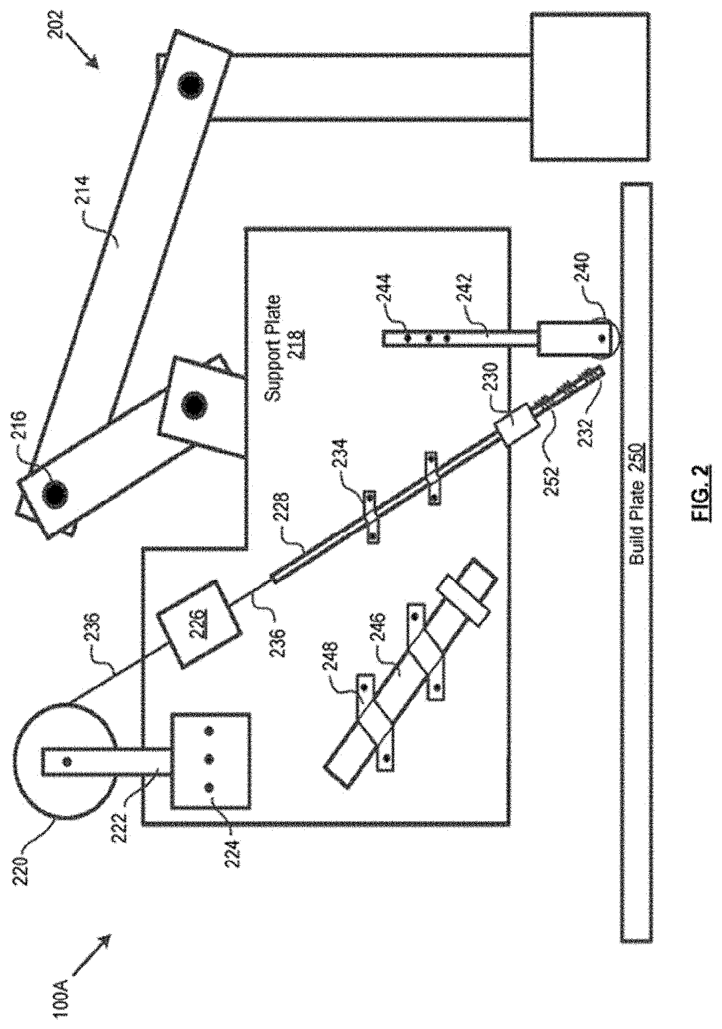
[0087] FIG. 2 depicts a feedstock-shaping deposition system 100A in accordance with an illustrative embodiment of the present disclosure. System 100A may comprise the functional elements of system 100 depicted in FIG. 1.
[0088] In system 100A of FIG. 2, the positioning subsystem 102 may be a notional robotic arm 202. The robotic arm can be coupled to support plate 218, which supports the various subsystems and elements of system 100A. The robotic arm 202 can move the support plate 218, and all subsystems/elements attached thereto, so as to position the system to deliver a feedstock to a desired point in space consistent with the build instructions.
[0089] In some instances, the robotic arm 202 may be appropriately configured with rigid members 214 and joints 216 to provide six degrees of freedom (three in translation: x, y, and z axes; three in orientation: pitch, yaw, and roll). Printing with such a robotic arm is described, for example, in Ser. No. 14/184,010, previously referenced.
[0090] In other instances, the positioning subsystem 102 may comprise a gantry (not depicted) having one or two translational degrees of freedom (x and/or y axes). The build plate (on which the object is printed) may move in the z direction (and possibly the x or y direction depending on the gantry capabilities), such that three degrees of freedom are provided for the build. In other instances (not depicted), a robotic arm can be supported by a gantry. A robotic arm, other multi-axis end effector, or gantry system may be designed or specified to provide the requisite functionality for system 100A.
[0091] In system 100A, feed subsystem 104 includes spool 220, feed motor 226, feed tube 228, and cutter 230. Spool 220 may be rotatably coupled to member 222, the latter of which is attached (e.g., via bolts 224, etc.) to support plate 218. At least one feedstock 236 may be wound around spool 220. The at least one feedstock may pass through motor 226, feed tube 228, and cutter 230. Motor 226 can draws the feedstock 236 from spool 220. As it passes through cutter 230, the feedstock 236 may be sized in accordance with build instructions. Feed tube 228 may be attached to support plate 218, such as via clamps 234.
[0092] After sizing using the in-line cutter 230, feedstock 236 may be heated using the preheating subsystem 106. In system 100A, the preheating subsystem may be a direct-contact heater 252, such as in the form of heating tape, heating cord, etc. The heater may be wrapped around the exterior of feed tube 228 below in-line cutter 230. Direct-contact heater 352 may be controlled to heat feedstock 236 to a temperature at or above its glass transition temperature, but below its melting point.
[0093] A sized, preheated segment of feedstock 236 may be delivered to build plate 250 from delivery end 232 of feed tube 228. In some instances, the delivery end 232 of the feed tube 228 may be configured and/or positioned to deliver the feedstock directly underneath the feedstock shaper 110. The feedstock shaper may be a roller 240. The roller can rotate about pin 241 but may be rigidly coupled to support plate 218 via member 242 and bolts 244. Although, the roller 240 may be free to rotate about pin 241 along the x-direction, the roller may also be rigidly coupled to support plate 218 with respect to movements in along the y-direction and the z-direction.
[0094] In system 100A, focused heat source 108 may be laser 246, such as a diode or fiber laser, although other types of lasers may suitably be used. Laser 246 can be rigidly coupled to support plate 218, such as via clamps 248.
[0095] Laser 246 may be aligned to illuminate the sized segment of the at least one feedstock that was delivered to the build plate 250. The laser can heat the feedstock to its melting point for incorporation into the build object.
[0096] The laser may be used as focused heat source 108 because it enables precise and accurate control of the processing temperature. Since the laser spot size may be precisely controlled, the laser can be directed to heat both an underlying previously deposited layer, as well as the currently deposited layer, to melting. By melting the underlying layer during the deposition process, the bonding and adhesion between the layers can increase, enhancing the overall mechanical properties of the build object.
[0097] Robotic arm 202 positions support plate 218 such that roller 240 applies pressure to the deposited feedstock. The applied pressure ensures that the feedstock sticks and adheres to the underlying layer. In the absence of such pressure, gravity may be available to bond and adhere the feedstock to the underlying layer, providing a relatively weak interface.
[0098] Furthermore, the applied pressure can reshape the cross section of the feedstock from cylindrical to rectangular. The cylindrical towpreg may be transformed into a rectangular tape, rather than transforming from a circular cross-section to an ellipsoidal cross section. Ellipsoidal-shaped filaments may result in gaps and voids in the build object. The gaps and voids at interfaces can act as nucleation sites for crack propagation, negatively impacting the mechanical properties of the build object.
[0099] The rectangular shape (i.e., tape form factor) may be desired for the deposited feedstock because an object constructed therefrom will have minimal void space. The reduction in void space can result in printed objects having relatively better material properties.
[0100] FIG. 3 depicts the feedstock-shaping deposition system 100B in accordance with an illustrative embodiment of the present disclosure. System 100B can comprise all of the functional elements of system 100 depicted in FIG. 1.
[0101] The various subsystems/elements of system 100B are embodied as in system 100B of FIG. 3, with the exception of preheating subsystem 106. That is, positioning subsystem 102 may be a robotic arm 202. The feed subsystem 104 can comprise a pulley 220, feed motor 226, feed tube 228, and cutter 230. The focused heat source 108 may be a laser 246. The feedstock shaper 110 can be a roller 240.
[0102] In system 100B, the preheating subsystem 106 may be a forced hot air system, such as hot air blower 354. The slots 356 can be formed in the feed tube 228 below the in-line cutter 230, and the hot air from blower 354 may be directed at that portion of the feed tube.
[0103] The hot air blower 354 may be controlled to heat feedstock 236 to a temperature at or above its glass transition temperature, but below its melting point.
[0104] FIG. 4 illustrates the feedstock-shaping deposition system 100C in accordance with an illustrative embodiment of the present disclosure. System 100C may comprise all of the functional elements of system 100 depicted in FIG. 1.
[0105] The various subsystems of system 100C may be embodied as in systems 100B and 100A, with the exception of preheating subsystem 106. That is, positioning subsystem 102 may comprise one or more elements selected from the group consisting of robotic arm 202, feed subsystem 104 includes pulley 220, feed motor 226, feed tube 228, and cutter 230. The focused heat source 108 may be a laser 246. The filament shaper 110 may be a roller 240.
[0106] In system 100C, preheating subsystem 106 may be a laser 458. The laser 458 may have a lower power rating (or is operated at lower power) than laser 246. The beam from laser 458 can be directed at the portion of feed tube 228 below in-line cutter 240. Laser 458 may be controlled to heat filament 236 to a temperature at or above its glass transition temperature, but below its melting point.
[0107] FIG. 5 depicts filament-shaping deposition system 100D in accordance with an illustrative embodiment of the present disclosure. System 100D includes all of the functional elements of system 100 depicted in FIG. 1.
[0108] The various subsystems of system 100D are embodied as in systems 100C, 100B and 100A, with the exception of preheating subsystem 106. The positioning subsystem 102 may be a robotic arm 202. The feed subsystem 104 may comprise pulley 220, feed motor 226, feed tube 228, and cutter 230. The focused heat source 108 may be a laser 246. The filament shaper 110 can be a roller 240.
[0109] In system 100D, laser 246 can serve as focused heat source 108 and preheating subsystem 106. Beam splitter 560 may split the beam from laser 246 into two beams of unequal intensity. Beam 562, having relatively lower intensity, may be focused on the portion of feed tube 228 below in-line cutter 230 for preheating the feedstock. The split may be controlled so that beam 562 heats feedstock 236 to a temperature at or above its glass transition temperature, but below its melting point. Beam 564, having relatively higher intensity, may be focused on the feedstock that is delivered to the build surface. The intensity of the beam can be suitable for raising the temperature of the preheated feedstock to its melting point.
[0110] FIG. 6 depicts a material-extrusion 3D printer 600B including pinch rollers 670, feed tube 672, heating block 674, extrusion nozzle 676, preheating subsystem 678 in accordance with the present teachings. The pincher rollers 670, which are driven by a motor (not depicted), may pull feedstock 236 from a spool (not depicted) through feed tube 672. The feedstock may be heated to melting into heating block 674. The heated feedstock may be forced out of extrusion nozzle 676 at a reduced diameter. Preheat can be applied anywhere along feed tube 672 to a temperature at or above the glass transition temperature of the feedstock (but less than the melting point). Preheating subsystem 678 may be a direct contact heater (as in system 100A of FIG. 2) or a hot-air blower (as in system 100B of FIG. 3). Other embodiments of preheating subsystem 678 that is suitable for a material-extrusion-based 3D printer may suitably be used.
[0111] FIG. 7 depicts a directed energy deposition 3D printer 700B including preheating subsystem 794 in accordance with the present teachings. A laser (not depicted) may generate beam 780. The feed lines 782 may deliver powder feed 784. The shield gas lines 786 can deliver shield gas 788 to build surface 790. Energy (e.g., laser light, etc.) may be directed to a narrow, focused region on substrate 792, melting the substrate and the powdered feed material 784 that is being deposited into the substrate's melt pool. (In printer 700B, the shield-gas line on the right of FIG. 7B is omitted for clarity.) Preheat can be applied anywhere along feed lines 782 to preheat the feed to a temperature at or above the glass transition temperature of the polymer feed (but less than the melting point). Preheating subsystem 794 may be a direct contact heater (as in system 100A of FIG. 2) or a hot-air blower (as in system 100B of FIG. 3). Other embodiments of preheating subsystem 794 that are suitable for a material-extrusion-based 3D printer may suitably be used.
Computer Control Systems
[0112] The present disclosure provides computer control systems that are programmed to implement methods of the disclosure. FIG. 12 shows a computer system 1201 that is programmed or otherwise configured to implement 3D printing methods and systems of the present disclosure. The computer system 1201 can regulate various aspects of methods the present disclosure, such as, for example, preheating, at a first location in an additive manufacturing apparatus, a feed comprising a polymer material to a temperature in excess of a glass transition temperature and below a melting point of the polymer material.
[0113] The computer system 1201 includes a central processing unit (CPU, also "processor" and "computer processor" herein) 1205, which can be a single core or multi core processor, or a plurality of processors for parallel processing. The computer system 1201 also includes memory or memory location 1210 (e.g., random-access memory, read-only memory, flash memory), electronic storage unit 1215 (e.g., hard disk), communication interface 1220 (e.g., network adapter) for communicating with one or more other systems, and peripheral devices 1225, such as cache, other memory, data storage and/or electronic display adapters. The memory 1210, storage unit 1215, interface 1220 and peripheral devices 1225 are in communication with the CPU 1205 through a communication bus (solid lines), such as a motherboard. The storage unit 1215 can be a data storage unit (or data repository) for storing data. The computer system 1201 can be operatively coupled to a computer network ("network") 1230 with the aid of the communication interface 1220. The network 1230 can be the Internet, an internet and/or extranet, or an intranet and/or extranet that is in communication with the Internet. The network 1230 in some cases is a telecommunication and/or data network. The network 1230 can include one or more computer servers, which can enable distributed computing, such as cloud computing. The network 1230, in some cases with the aid of the computer system 1201, can implement a peer-to-peer network, which may enable devices coupled to the computer system 1201 to behave as a client or a server.
[0114] The CPU 1205 can execute a sequence of machine-readable instructions, which can be embodied in a program or software. The instructions may be stored in a memory location, such as the memory 1210. The instructions can be directed to the CPU 1205, which can subsequently program or otherwise configure the CPU 1205 to implement methods of the present disclosure. Examples of operations performed by the CPU 1205 can include fetch, decode, execute, and writeback.
[0115] The CPU 1205 can be part of a circuit, such as an integrated circuit. One or more other components of the system 1201 can be included in the circuit. In some cases, the circuit is an application specific integrated circuit (ASIC).
[0116] The storage unit 1215 can store files, such as drivers, libraries and saved programs. The storage unit 1215 can store user data, e.g., user preferences and user programs. The computer system 1201 in some cases can include one or more additional data storage units that are external to the computer system 1201, such as located on a remote server that is in communication with the computer system 1201 through an intranet or the Internet.
[0117] The computer system 1201 can communicate with one or more remote computer systems through the network 1230. For instance, the computer system 1201 can communicate with a remote computer system of a user (e.g., customer or operator of a 3D printing system). Examples of remote computer systems include personal computers (e.g., portable PC), slate or tablet PC's (e.g., Apple.RTM. iPad, Samsung.RTM. Galaxy Tab), telephones, Smart phones (e.g., Apple.RTM. iPhone, Android-enabled device, Blackberry.RTM.), or personal digital assistants. The user can access the computer system 1201 via the network 1230.
[0118] Methods as described herein can be implemented by way of machine (e.g., computer processor) executable code stored on an electronic storage location of the computer system 1201, such as, for example, on the memory 1210 or electronic storage unit 1215. The machine executable or machine readable code can be provided in the form of software. During use, the code can be executed by the processor 1205. In some cases, the code can be retrieved from the storage unit 1215 and stored on the memory 1210 for ready access by the processor 1205. In some situations, the electronic storage unit 1215 can be precluded, and machine-executable instructions are stored on memory 1210.
[0119] The code can be pre-compiled and configured for use with a machine having a processor adapted to execute the code, or can be compiled during runtime. The code can be supplied in a programming language that can be selected to enable the code to execute in a pre-compiled or as-compiled fashion.
[0120] Aspects of the systems and methods provided herein, such as the computer system 1801, can be embodied in programming. Various aspects of the technology may be thought of as "products" or "articles of manufacture," in some cases in the form of machine (or processor) executable code and/or associated data that is carried on or embodied in a type of machine readable medium. Machine-executable code can be stored on an electronic storage unit, such as memory (e.g., read-only memory, random-access memory, flash memory) or a hard disk. "Storage" type media can include any or all of the tangible memory of the computers, processors or the like, or associated modules thereof, such as various semiconductor memories, tape drives, disk drives and the like, which may provide non-transitory storage at any time for the software programming. All or portions of the software may at times be communicated through the Internet or various other telecommunication networks. Such communications, for example, may enable loading of the software from one computer or processor into another, for example, from a management server or host computer into the computer platform of an application server. Thus, another type of media that may bear the software elements includes optical, electrical and electromagnetic waves, such as used across physical interfaces between local devices, through wired and optical landline networks and over various air-links. The physical elements that carry such waves, such as wired or wireless links, optical links or the like, also may be considered as media bearing the software. As used herein, unless restricted to non-transitory, tangible "storage" media, terms such as computer or machine "readable medium" refer to any medium that participates in providing instructions to a processor for execution.
[0121] Hence, a machine readable medium, such as computer-executable code, may take many forms, including but not limited to, a tangible storage medium, a carrier wave medium or physical transmission medium. Non-volatile storage media include, for example, optical or magnetic disks, such as any of the storage devices in any computer(s) or the like, such as may be used to implement the databases, etc. shown in the drawings. Volatile storage media include dynamic memory, such as main memory of such a computer platform. Tangible transmission media include coaxial cables; copper wire and fiber optics, including the wires that comprise a bus within a computer system. Carrier-wave transmission media may take the form of electric or electromagnetic signals, or acoustic or light waves such as those generated during radio frequency (RF) and infrared (IR) data communications. Common forms of computer-readable media therefore include for example: a floppy disk, a flexible disk, hard disk, magnetic tape, any other magnetic medium, a CD-ROM, DVD or DVD-ROM, any other optical medium, punch cards paper tape, any other physical storage medium with patterns of holes, a RAM, a ROM, a PROM and EPROM, a FLASH-EPROM, any other memory chip or cartridge, a carrier wave transporting data or instructions, cables or links transporting such a carrier wave, or any other medium from which a computer may read programming code and/or data. Many of these forms of computer readable media may be involved in carrying one or more sequences of one or more instructions to a processor for execution.
[0122] The computer system 1201 can include or be in communication with an electronic display 1235 that comprises a user interface (UI) 1240 for providing, for example, a print head tool path to a user. Examples of UI's include, without limitation, a graphical user interface (GUI) and web-based user interface.
[0123] Methods and systems of the present disclosure can be implemented by way of one or more algorithms. An algorithm can be implemented by way of software upon execution by the central processing unit 1205. The algorithm can, for example, partition a computer model of a part and generate a mesh array from the computer model.
[0124] The computer system 1201 can include a 3D printing system. The 3D printing system may include one or more 3D printers. A 3D printer may be, for example, a fused filament fabrication (FFF) printer. Alternatively or in addition to, the computer system 1201 may be in remote communication with the 3D printing system, such as through the network 1230.
[0125] While preferred embodiments of the present invention have been shown and described herein, it will be obvious to those skilled in the art that such embodiments are provided by way of example only. It is not intended that the invention be limited by the specific examples provided within the specification. While the invention has been described with reference to the aforementioned specification, the descriptions and illustrations of the embodiments herein are not meant to be construed in a limiting sense. Numerous variations, changes, and substitutions will now occur to those skilled in the art without departing from the invention. Furthermore, it shall be understood that all aspects of the invention are not limited to the specific depictions, configurations or relative proportions set forth herein which depend upon a variety of conditions and variables. It should be understood that various alternatives to the embodiments of the invention described herein may be employed in practicing the invention. It is therefore contemplated that the invention shall also cover any such alternatives, modifications, variations or equivalents. It is intended that the following claims define the scope of the invention and that methods and structures within the scope of these claims and their equivalents be covered thereby.
* * * * *
D00001
D00002
D00003
D00004
D00005
D00006
D00007
D00008
D00009
XML
uspto.report is an independent third-party trademark research tool that is not affiliated, endorsed, or sponsored by the United States Patent and Trademark Office (USPTO) or any other governmental organization. The information provided by uspto.report is based on publicly available data at the time of writing and is intended for informational purposes only.
While we strive to provide accurate and up-to-date information, we do not guarantee the accuracy, completeness, reliability, or suitability of the information displayed on this site. The use of this site is at your own risk. Any reliance you place on such information is therefore strictly at your own risk.
All official trademark data, including owner information, should be verified by visiting the official USPTO website at www.uspto.gov. This site is not intended to replace professional legal advice and should not be used as a substitute for consulting with a legal professional who is knowledgeable about trademark law.