An Electrostatic Dust Collecting Module An Electrostatic Air Purifier Thereof
Hu; Hairong ; et al.
U.S. patent application number 15/532296 was filed with the patent office on 2020-05-07 for an electrostatic dust collecting module an electrostatic air purifier thereof. The applicant listed for this patent is Ningbo Zhekai Electric Co., Ltd.. Invention is credited to Hairong Hu, Zhangbin Xiao.
| Application Number | 20200139381 15/532296 |
| Document ID | / |
| Family ID | 55366469 |
| Filed Date | 2020-05-07 |


| United States Patent Application | 20200139381 |
| Kind Code | A1 |
| Hu; Hairong ; et al. | May 7, 2020 |
An Electrostatic Dust Collecting Module An Electrostatic Air Purifier Thereof
Abstract
An electrostatic precipitation module includes a plurality of conductive precipitation electrode plates and a plurality of non-precipitation electrode plates. The plurality of precipitation electrode plates are interlacedly distributed along the length of the first connecting rib; the precipitation electrode plates 1 are made from conductive plastic material by injection molding, and the metal conductor is embedded inside the first connecting rib by in-mold injection molding, so that a precipitation electrode plate module 9 is formed; a non-precipitation electrode plate module is formed by the similar structure. After the precipitation electrode plate module 9 and the non-precipitation electrode plate module 14 are assembled relatively, the precipitation electrode plates 1 and the non-precipitation electrode plates 10 form an electrostatic precipitation module 15. The present invention also discloses an electrostatic air purifier using the electrostatic precipitation modules which can be assembled quickly, improves the uniformity of electric field distribution and has excellent electrostatic absorption performance.
| Inventors: | Hu; Hairong; (Cixi City, CN) ; Xiao; Zhangbin; (Cixi City, CN) | ||||||||||
| Applicant: |
|
||||||||||
|---|---|---|---|---|---|---|---|---|---|---|---|
| Family ID: | 55366469 | ||||||||||
| Appl. No.: | 15/532296 | ||||||||||
| Filed: | December 18, 2015 | ||||||||||
| PCT Filed: | December 18, 2015 | ||||||||||
| PCT NO: | PCT/CN2015/000910 | ||||||||||
| 371 Date: | June 1, 2017 |
| Current U.S. Class: | 1/1 |
| Current CPC Class: | B03C 2201/10 20130101; B03C 3/64 20130101; Y02A 50/2357 20180101; B03C 3/47 20130101; B03C 3/82 20130101; B03C 3/41 20130101; B03C 3/08 20130101; B03C 2201/28 20130101; B03C 3/86 20130101; B03C 3/12 20130101; B03C 3/368 20130101; F24F 3/16 20130101 |
| International Class: | B03C 3/08 20060101 B03C003/08; B03C 3/47 20060101 B03C003/47; B03C 3/82 20060101 B03C003/82; B03C 3/64 20060101 B03C003/64 |
Foreign Application Data
| Date | Code | Application Number |
|---|---|---|
| Dec 3, 2015 | CN | 201510881195.X |
Claims
1. An electrostatic precipitation module, comprising: a first connecting rib; a metal conductor embedded inside the first connecting rib along a length of the connecting rib; a plurality of conductive precipitation electrode plates connected to the first connecting rib and distributed along the length of the first connecting rib; a first set of connecting frames between which the plurality of conductive precipitation electrode plates and the first connecting rib are disposed and formed a precipitation electrode plate module; a second connecting rib; a plurality of non-precipitation electrode plates connected to the second connecting rib and distributed along a length of the second connecting rib; and a second set of connecting frames between which the plurality of non-precipitation electrode plates and the second connecting rib are disposed and formed a non-precipitation electrode plate module, wherein, the precipitation electrode plates are made from conductive plastic material by injection molding, and the metal conductor is embedded inside the first connecting rib by in-mold injection molding, the non-precipitation electrode plates are made from conductive plastic material by injection molding, the precipitation electrode plate module is placed parallel and adjacent to the non-precipitation electrode plate module such that the plurality of non-precipitation electrode plates and the plurality of conductive precipitation electrode plates are interlacedly disposed.
2. The electrostatic precipitation module of claim 1, wherein upper portions of the precipitation electrode plates protrude above the first set of connecting frames while lower portions thereof extending into the first set of connecting frames; upper portions of the non-precipitation electrode plates protrude above the second set of connecting frames while lower portions thereof extending into the second set of connecting frames.
3. The electrostatic precipitation module of claim 2, wherein the first set of connecting frames are parallel plates with an equal height.
4. The electrostatic precipitation module of claim 1, wherein a first evading gap is formed on the precipitation electrode plate module at a position lining up with the first connecting rib; and a second evading gap is also formed on the precipitation electrode plate module at a position lining up with the second connecting rib.
5. The electrostatic precipitation module of claim 1, wherein in the precipitation electrode plate module, the precipitation electrode plates are mounted inside a first insulating electrode plate positioning frame; and in the non-precipitation electrode plate module, the non-precipitation electrode plates are mounted inside a second insulating electrode plate positioning frame.
6. The electrostatic precipitation module of claim 5, wherein the metal conductor of the precipitation electrode plate module is strip-shaped, and extends out from the first electrode plate positioning frame to form a first bent contact portion; and a second contact portion is provided on a surface of an outermost non-precipitation electrode plate in the non-precipitation electrode plate module to form an conductive one-piece member.
7. An electrostatic air purifier using the electrostatic precipitation module of claim 1, comprising: a front shell with an air outlet and a rear cover with an air inlet, which are respectively used for sucking and exhausting air; an electrostatic precipitation module is disposed within a space between the front shell and the rear cover and absorbs negatively charged dust particles in an air flow by static electricity; a fan assembly is disposed between the front shell and the electrostatic precipitation module and used for facilitating the air flow to flow from the air inlet to the air outlet; and an anion emitter is disposed between the front shell and the fan assembly and used for emitting anions to ionize the dust particles in the air flow so that the dust particles are negatively charged.
8. The electrostatic air purifier of claim 7, wherein a middle frame for fixing the non-precipitation electrode plate module in the electrostatic precipitation module is disposed between the front shell and the rear cover.
9. The electrostatic air purifier of claim 7, wherein a microswitch is attached to a line connecting the electrostatic precipitation module to a high-voltage power supply; the microswitch connects to a first protrusion on the rear cover; and when the microswitch is turned on, after the rear cover is closed in place, the electrostatic precipitation module will be connected to the high-voltage power supply.
10. The electrostatic air purifier of claim 7, wherein the first contact portion of the precipitation electrode plate module and the second contact portion of the non-precipitation electrode plate module are connected to an anode and a cathode of the high-voltage power supply through an elastic anode contact sheet and an elastic cathode contact sheet.
11. The electrostatic air purifier of claim 10, wherein a rotatable discharge plate with a first end and a second end is provided being capable of rotating around a rotating axis, and the elastic anode contact sheet and the elastic cathode contact sheet respectively locates corresponding to the first end and the second end of the discharge plate; a spring resists the second end of the discharge plate, so that the first end and the second end of the discharge plate can keep to contact respectively with the elastic anode contact sheet and the elastic cathode contact sheets; a second protrusion of the rear cover can resist on the first end of the discharge plate to make the first end and the second end of the discharge plate apart from the elastic anode contact sheet and the elastic cathode contact sheets; when the rear cover is disassembled, the first end of the discharge plate is not resisted by the second protrusion of the rear cover, so that the two ends of the discharge plate can contact with the elastic anode contact sheet and the elastic cathode contact sheets and the precipitation electrode plate module and the non-precipitation electrode plate module are connected for discharging.
12. The electrostatic air purifier of claim 11, wherein the discharge plate comprises a plastic baseplate with a top surface and a bottom surface, the discharge plate has an abutment portion disposed on the top surface of the plastic baseplate, and two metal shrapnels defining the first end and the second end of the discharge plate are both disposed on the bottom surface of the plastic baseplate.
Description
RELATE APPLICATIONS
[0001] This application is a national phase entrance of and claims benefit to PCT Application for an electrostatic precipitation module and an electrostatic air purifier thereof, PCT/CN2015/000910, filed on Dec. 18, 2015, which claims benefit to Chinese Patent Application 201510881195.X, filed on Dec. 3, 2015. The specifications of both applications are incorporated here by this reference.
TECHNICAL FIELD OF THE INVENTION
[0002] The present invention relates to the technical field of electrostatic precipitation, and in particular to an electrostatic precipitation module and an electrostatic air purifier thereof.
BACKGROUND OF THE INVENTION
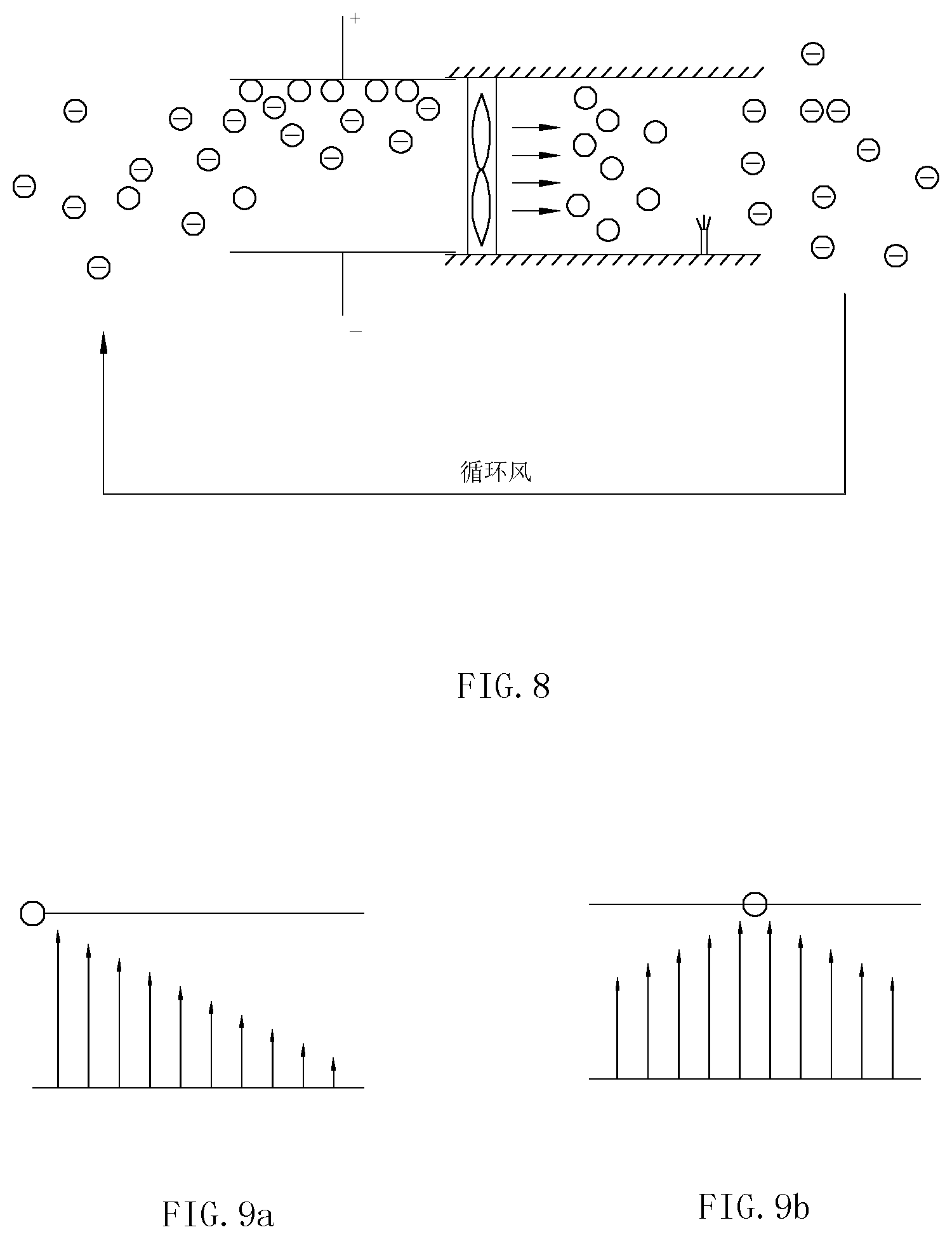
[0003] An electrostatic precipitator may form an electric field, and dust particles in air are charged by the corona effect when the dust in air passes through the electric field. An electrostatic precipitation device generally consists of a plurality of parallel electrode plates, with a high-voltage (e.g., several KV, generally 3-10 KV) power supply provided between the electrode plates to form an electric field. Charged dust particles are deflected under stress when passing through the electric field, and are eventually trapped on the electrode plates. The electrode plates are generally made of metal plates which are usually manufactured by sheet stamping. This structure has the following disadvantages: the assembly of the manufactured electrode plates is relatively troublesome because dozens of electrode plates are to be fixed and mounted one by one with a uniform interval, and it is thus difficult to control the process; in addition, since stamping parts may have many sharp edges and burrs, discharging tips will be formed when a high voltage is applied to the electrode plates, resulting in, on one hand, insufficient voltage and deteriorated performance, and on the other hand, the generation of excessive ozone which is harmful to the user's health. The electrode plates may be made of profiles. In this case, dozens of profiles are also to be fixed and mounted one by one, and the process is also troublesome. Although the problem of burrs caused by stamping is solved and it is thus advantageous to the improvement of performance, the material cost is high. Some electrode plates may be made of plastic material. If material with a high conductivity is used, it is also likely to result in breakdown on two poles, decreased voltage and deteriorated performance; however, if material with a lower conductivity is used, it is likely to result in non-uniform electric field intensity and non-uniform absorption capacity if electrodes are not manufactured well. Moreover, since a contact is simply formed besides electrodes in the conventional design, as shown in FIG. 9a, the potential cross the two poles gradually decreases from a contact to a position away from the contact, so that the absorption performance is influenced.
[0004] In addition, a Chinese Patent CN204074260U (Application No.: 201320459622.1) entitled ELECTROSTATIC PRECIPITATION BOX, the material structure of electrode plates is improved in the disclosed precipitation box, the problems of ignition and the generation of ozone are thus avoided, and moreover, the uniform interval among the electrode plates can also be ensured effectively. However, the electrode plates still need to be mounted one by one, and the mounting process is relatively complicated. Furthermore, in the electrostatic precipitation devices disclosed in a Chinese Patent Application CN104689921A (Application No.: 201510065803.X) entitled ELECTROSTATIC PRECIPITATOR and a Chinese Patent CN204583490U (Application No.: 201420794435.3) entitled PRECIPITATION UNIT AND ELECTROSTATIC AIR PURIFICATION DEVICE, electrode plates are to be mounted one by one, so that quickly mounting the electrode plates cannot be realized.
SUMMARY OF THE INVENTION
[0005] A first technical problem to be solved by the present invention is to provide an electrostatic precipitation module which can be assembled quickly, improves the uniformity of electric field distribution and has excellent electrostatic absorption performance.
[0006] A second technical problem to be solved by the present invention is to provide an electrostatic air purifier which is easy to assemble and produce and is excellent in absorption performance.
[0007] To solve the first technical problem, the electrostatic precipitation module comprises: a first connecting rib; a metal conductor embedded inside the first connecting rib along a length of the connecting rib; a plurality of conductive precipitation electrode plates connected to the first connecting rib and distributed along the length of the first connecting rib; a first set of connecting frames between which the plurality of conductive precipitation electrode plates and the first connecting rib are disposed and formed a precipitation electrode plate module; a second connecting rib; a plurality of non-precipitation electrode plates connected to the second connecting rib and distributed along a length of the second connecting rib; and a second set of connecting frames between which the plurality of non-precipitation electrode plates and the second connecting rib are disposed and formed a non-precipitation electrode plate module; wherein, the precipitation electrode plates are made from conductive plastic material by injection molding, and the metal conductor is embedded inside the first connecting rib by in-mold injection molding, the non-precipitation electrode plates are made from conductive plastic material by injection molding, the precipitation electrode plate module is placed parallel and adjacent to the non-precipitation electrode plate module such that the plurality of non-precipitation electrode plates and the plurality of conductive precipitation electrode plates are interlacedly disposed.
[0008] As an improvement, upper portions of the precipitation electrode plates protrude is above the first set of connecting frames while lower portions thereof extending into the first set of connecting frames; upper portions of the non-precipitation electrode plates protrude is above the second set of connecting frames while lower portions thereof extending into the second set of connecting frames.
[0009] Preferably, the first set of connecting frames is parallel plates with an equal height.
[0010] Preferably, a first evading gap is formed on the precipitation electrode plate module at a position lining up with the second connecting rib; and a second evading gap is also formed on the precipitation electrode plate module at a position lining up with the second connecting rib.
[0011] As a further improvement, in the precipitation electrode plate module, the precipitation electrode plates are mounted inside a first insulating electrode plate positioning frame; and in the non-precipitation electrode plate module, the non-precipitation electrode plates are mounted inside a second insulating electrode plate positioning frame.
[0012] Preferably, the metal conductor of the precipitation electrode plate module is strip-shaped, and extends out from the first electrode plate positioning frame to form a first bent contact portion; and a second contact portion is provided on a surface of an outermost non-precipitation electrode plate in the non-precipitation electrode plate module to form an conductive one-piece member.
[0013] To solve the second technical problem, an electrostatic air purifier using any of electrostatic precipitation modules described above comprises:
[0014] a front shell with an air outlet and a rear cover with an air inlet, which are respectively used for sucking and exhausting air;
[0015] an electrostatic precipitation module is disposed within a space between the front shell and the rear cover and absorbs negatively charged dust particles in an air flow by static electricity;
[0016] a fan assembly is disposed between the front shell and the electrostatic precipitation module and used for facilitating the air flow to flow from the air inlet to the air outlet; and
[0017] an anion emitter is disposed between the front shell and the fan assembly and used for emitting anions to ionize the dust particles in the air flow so that the dust particles are negatively charged.
[0018] Preferably, a middle frame for fixing the non-precipitation electrode plate module in the electrostatic precipitation module is disposed between the front shell and the rear cover.
[0019] Preferably, a microswitch is attached to a line connecting the electrostatic precipitation moduleto a high-voltage power supply; the microswitch connects to a first protrusion on the rear cover; and when the microswitch is turned on, after the rear cover is closed in place, the electrostatic precipitation module will be connected to the high-voltage power supply.
[0020] As an improvement, the first contact portion of the precipitation electrode plate module and the second contact portion of the non-precipitation electrode plate module are connected to an anode and a cathode of the high-voltage power supply through an elastic anode contact sheet and an elastic cathode contact sheet.
[0021] As an improvement, a rotatable discharge plate with a first end and a second end is provided being capable of rotating around a rotating axis, and the elastic anode contact sheet and the elastic cathode contact sheet respectively locates corresponding to the first end and the second end of the discharge plate; a spring resists the second end of the discharge plate, so that the first end and the second end of the discharge plate can keep to contact respectively with the elastic anode contact sheet and the elastic cathode contact sheets; a second protrusion of the rear cover can resist on the first end of the discharge plate to make the first end and the second end of the discharge plate apart from the elastic anode contact sheet and the elastic cathode contact sheets; when the rear cover is disassembled, the first end of the discharge plate is not resisted by the second protrusion of the rear cover, so that the two ends of the discharge plate can contact with the elastic anode contact sheet and the elastic cathode contact sheets and the precipitation electrode plate module and the non-precipitation electrode plate module are connected for discharging.
[0022] Preferably, the discharge plate comprises a plastic baseplate with a top surface and a bottom surface, the discharge plate has an abutment portion disposed on the top surface of the plastic baseplate, and two metal shrapnels defining the first end and the second end of the discharge plate are both disposed on the bottom surface of the plastic baseplate.
[0023] Compared with the prior art, the present invention has the following advantages.
[0024] By providing a metal conductor for enhancing the electric field distribution inside the connecting rib, the electric field distribution of the precipitation electrode plate module and the non-precipitation electrode plate module is more uniform, so that the electrostatic dust absorption performance is improved. Moreover, since the precipitation electrode plate module and the non-precipitation electrode plate are integrally formed by an injection molding machine, it is convenient for manufacturing and one pole works as a one-piece member, unlike metal stamping parts which are to be assembled one by one. In addition, the production is convenient and the production efficiency is high.
[0025] By using in-mold injection molding, the production cost is low.
[0026] There are no burrs and sharp edges on the plastic edges, the performance is excellent, and it is convenient for the subsequent assembly of the electrode precipitation module.
[0027] The conductivity of the plastic material is not required to be as good as that of metal, because a small resistance will not affect the performance of the whole precipitation module under a high voltage. Moreover, since the conductivity is slightly lower than that of metal, the disadvantage of ignition by using metal electrode plates is eliminated.
[0028] With an anion emitter structure, the duct particles are ionized and then negatively charged and thus easier to be absorbed by the electrostatic precipitation module, so that the purification effect is improved and the air is freshened.
[0029] By additionally providing a safety protection device, when the rear cover is opened, the electrostatic precipitation module is disconnected from the high-voltage power supply, and the precipitation electrode plate module and the non-precipitation electrode plate module are connected for discharging. In this way, the occurrence of electric shock of users is avoided, and it is safe and reliable. Furthermore, the safety protection device is simple, practical, easy to implement and low in cost.
BRIEF DESCRIPTION OF THE DRAWINGS
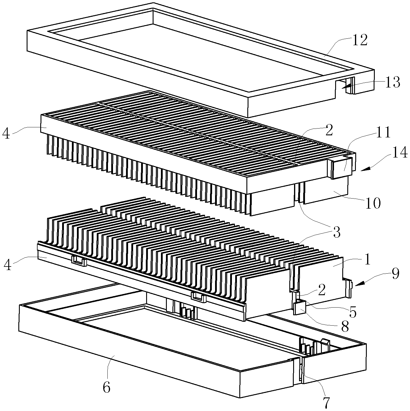
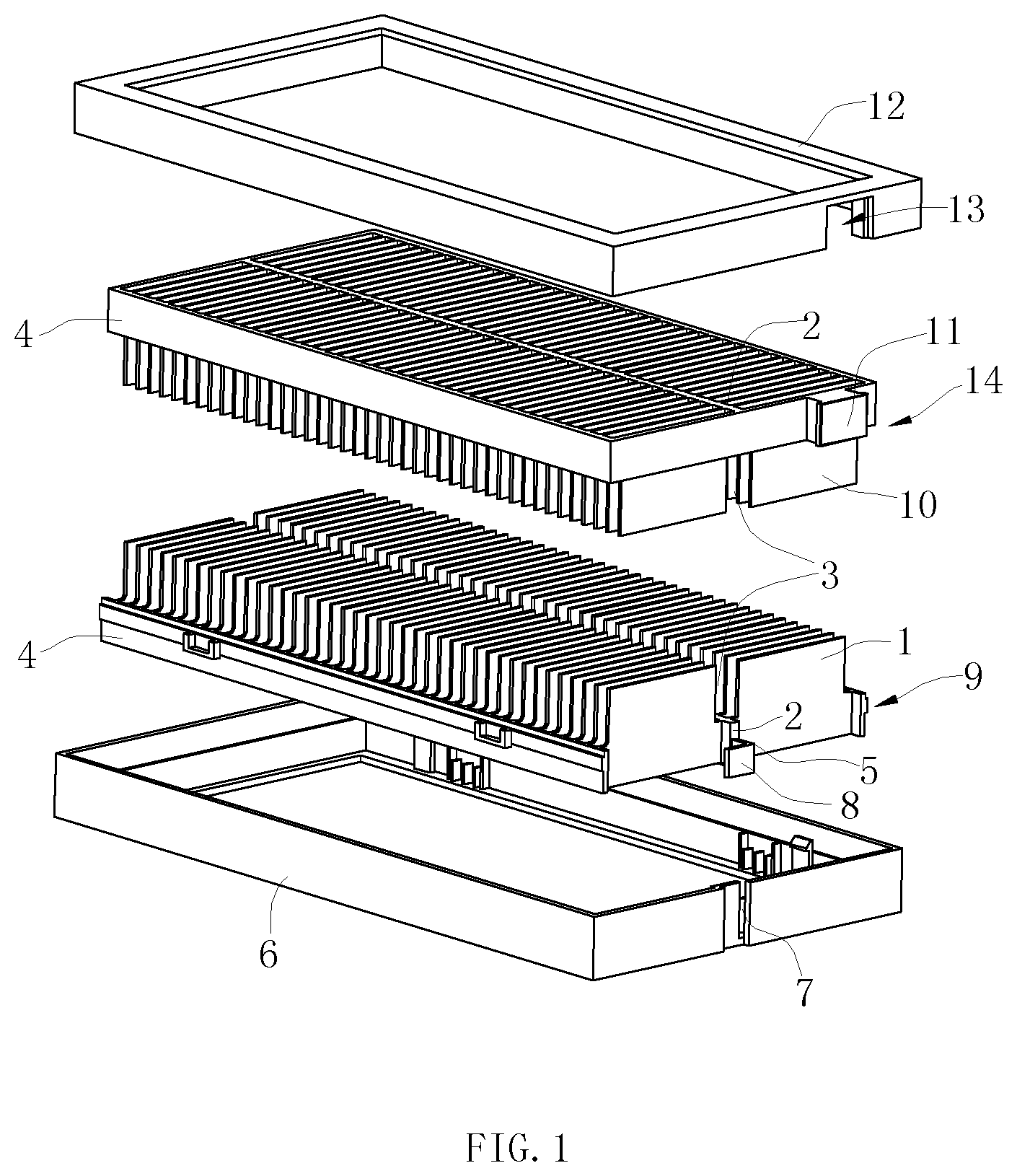
[0030] FIG. 1 is an exploded view of an electrostatic precipitation module according to an embodiment of the present invention;
[0031] FIG. 2 is a side view of the electrostatic precipitation module according to the embodiment of the present invention (when the electrostatic precipitation module has not been closed);
[0032] FIG. 3 is a side view of the electrostatic precipitation module according to the embodiment of the present invention (when the electrostatic precipitation module has been closed);
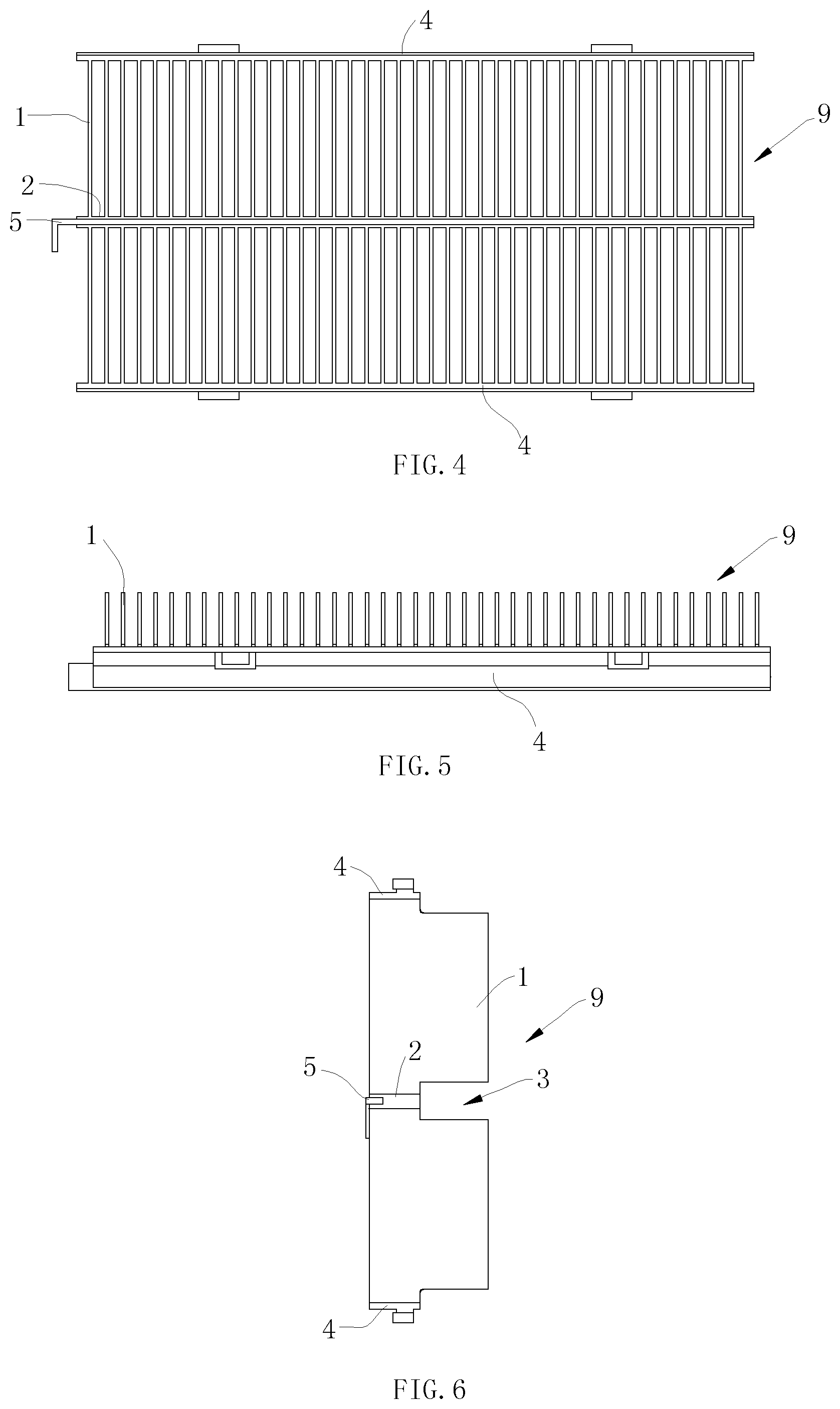
[0033] FIG. 4 is a top view of a precipitation electrode plate module of the electrostatic precipitation module according to the embodiment of the present invention;
[0034] FIG. 5 is a front view of the precipitation electrode plate module of the electrostatic precipitation module according to the embodiment of the present invention;
[0035] FIG. 6 is a side view of the precipitation electrode plate module of the electrostatic precipitation module according to the embodiment of the present invention;
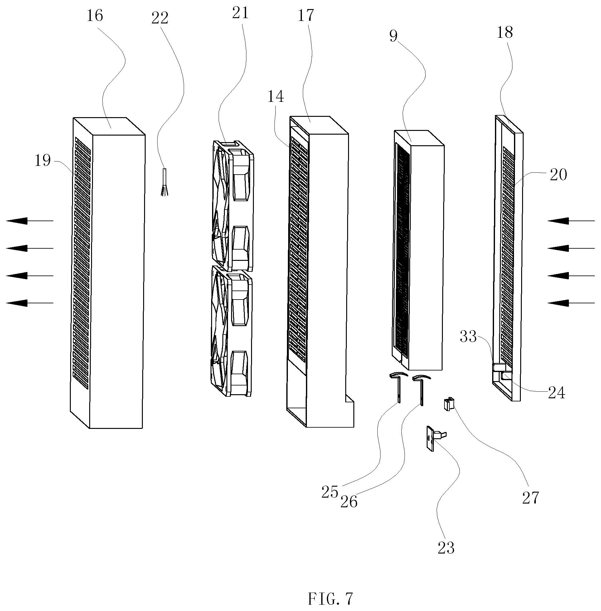
[0036] FIG. 7 is an exploded view of an electrostatic air purifier according to the embodiment of the present invention;
[0037] FIG. 8 is a basic principle diagram of the electrostatic air purifier according to the embodiment of the present invention;
[0038] FIG. 9a is a diagram of the electric field distribution of a conventional electrostatic precipitation module, and FIG. 9b is a diagram of the electric field distribution of the electrostatic precipitation module according to the embodiment of the present invention;
[0039] FIG. 10 is a front view of a safety device of the electrostatic air purifier according to the embodiment of the present invention, after the rear cover is taken down;
[0040] FIG. 11 is a sectional view in direction A-A of FIG. 10;
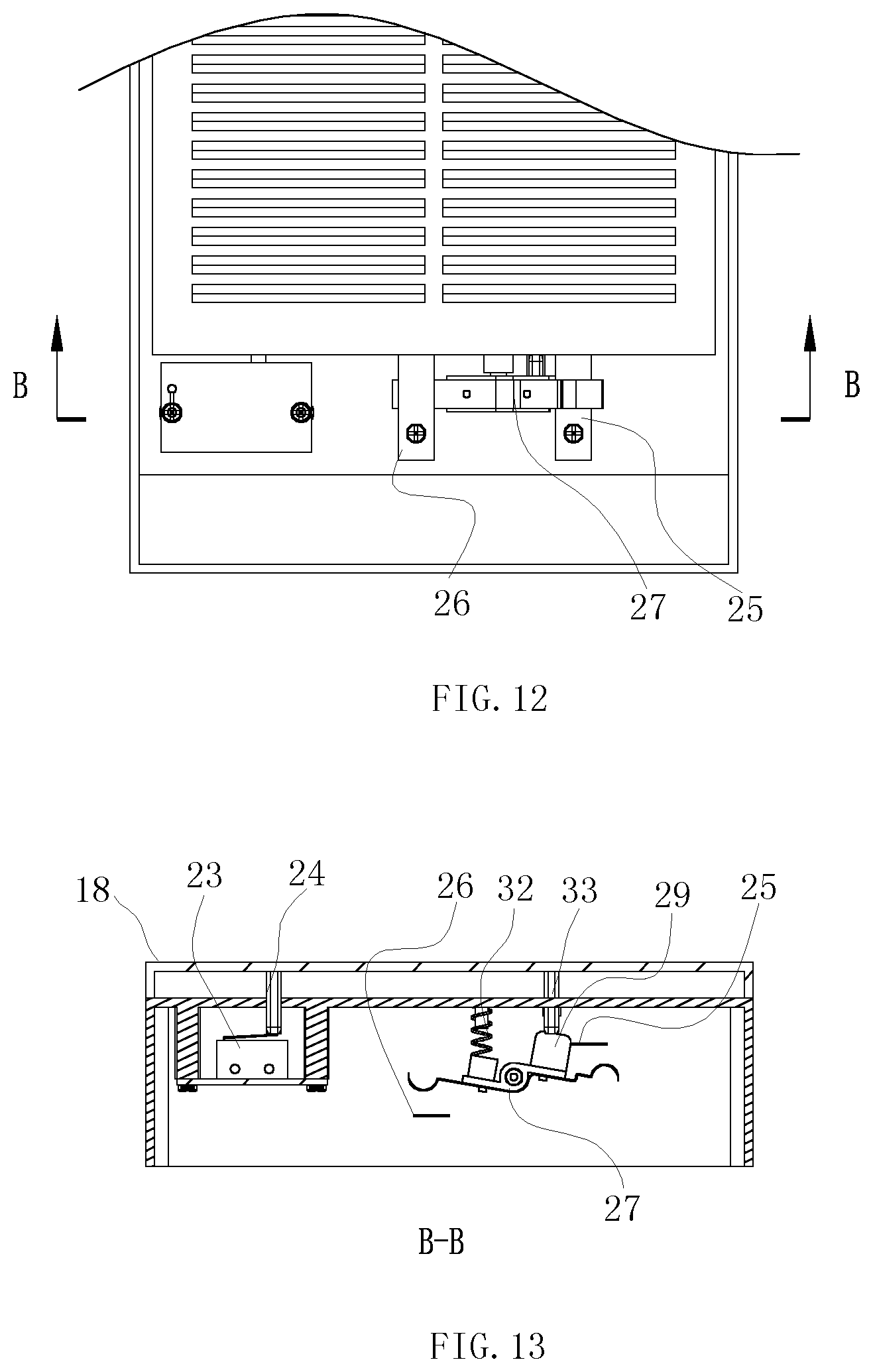
[0041] FIG. 12 is a front view of the safety device of the electrostatic air purifier according to the embodiment of the present invention, when the rear cover is covered;
[0042] FIG. 13 is a sectional view in direction B-B of FIG. 12;
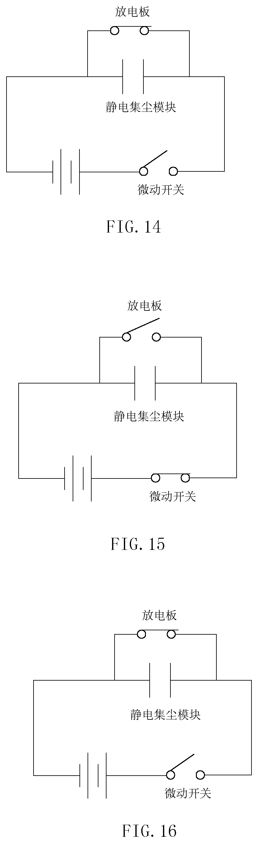
[0043] FIG. 14 is a schematic circuit diagram of the safety device of the electrostatic air purifier according to the embodiment of the present invention, when the rear cover is taken down;
[0044] FIG. 15 is a schematic circuit diagram of the safety device of the electrostatic air purifier according to the embodiment of the present invention, when the rear cover is covered; and
[0045] FIG. 16 is a schematic circuit diagram of the safety device according to the embodiment of the present invention for discharging at the moment that the rear cover is taken down.
DETAILED DESCRIPTION OF THE INVENTION
[0046] To enable a further understanding of the present invention content of the invention herein, refer to the detailed description of the invention and the accompanying drawings below:
[0047] FIGS. 1-6 show a preferred embodiment of the electrostatic precipitation module of the present invention. The electrostatic precipitation module comprising: a metal conductor 5; a first connecting rib 2; a plurality of conductive precipitation electrode plates 1; a first set of connecting frames 4; a second connecting rib 2; and a plurality of non-precipitation electrode plates 10.
[0048] The key of the present invention lies in that: the first connecting rib 2 in a middle position of the plurality of conductive precipitation electrode plates 1 and the plurality of precipitation electrode plates 1 is connected to the first connecting rib 2 and distributed along the length of the first connecting rib 1; and a first evading gap 3 is formed on the precipitation electrode plates 1 at a position lining up with the first connecting rib 2; if the overall height of the precipitation electrode plates 1 is 35 mm, the first connecting rib 2 has a height of 15 mm and the first evading gap 3 has a height of 20 mm; the precipitation electrode plates 1 are disposed in parallel between connecting frames 4; the connecting frames 4 are parallel plates with an equal height; upper portions of the precipitation electrode plates 1 protrude above the first set of connecting frames 4 while lower portions thereof extending into the first set of connecting frames 4; the precipitation electrode plates 1 are made from conductive plastic material by injection molding, and the metal conductor 5 for enhancing the electric field distribution is embedded inside the first connecting rib 2 by in-mold injection molding, so that a precipitation electrode plate module 9 is formed; the metal conductor 5 is strip-shaped; the conductive plastic material for the precipitation electrode plate module has a resistivity in an order of magnitude from 106 to 109 (in unit of .OMEGA.m); finally, in the precipitation electrode plate module 9, the precipitation electrode plates 1 are mounted inside a first insulating electrode plate positioning frame 6, so that one end of the strip-shaped metal conductor 5 passes through a notch 7 of the first electrode plate positioning frame 6 and then extends out from the first electrode plate positioning frame 6 to form a first bent contact portion 8; the first contact portion 8 is recessed into the notch 7 of the first electrode plate positioning frame, substantially flush with the frame edge surface.
[0049] Correspondingly, the second connecting rib 2 in a middle position of the plurality of non-non-precipitation electrode plates 100 and the plurality of non-precipitation electrode plates 10 is connected to the second connecting rib 2 and distributed along the length of the second connecting rib 1; and a second evading gap 3 is formed on the non-precipitation electrode plates 10 at a position lining up with the second connecting rib 2; if the overall height of the non-precipitation electrode plates 10 is 35 mm, the second connecting rib 2 has a height of 15 mm and the second evading gap 3 has a height of 20 mm so that there is an insufficient space between the precipitation electrode plates 1 and the non-precipitation electrode plates 10; the non-precipitation electrode plates 10 are disposed in parallel between connecting frames 4; the connecting frames 4 are parallel plates with an equal height; upper portions of the non-precipitation electrode plates 10 protrude above the second set of connecting frames 4 while lower portions thereof extending into the second set of connecting frames 4; the non-precipitation electrode plates 10 are made from conductive plastic material by injection molding, so that a non-precipitation electrode plate module 14 is formed; the metal conductor 5 is strip-shaped; the conductive plastic material for the precipitation electrode plate module has a resistivity in an order of magnitude from 10 to 105 (in unit of .OMEGA.m); a second contact portion 11 is provided on a surface of an outermost non-precipitation electrode plate 10 in the non-precipitation electrode plate module 14 to form an conductive one-piece member; finally, in the non-precipitation electrode plate module 14, the non-precipitation electrode plates 10 are mounted inside a second insulating electrode plate positioning frame 12, and a positioning port 13 is formed on the frame edge to expose the second contact portion 11, the second contact portion 11 is substantially flush with the frame edge.
[0050] After the precipitation electrode plate module 9 and the non-precipitation electrode plate module 14 are assembled relatively, the precipitation electrode plates 1 in the precipitation electrode plate module 9 and the non-precipitation electrode plates 10 in the non-precipitation electrode plate module 14 are alternately arranged at intervals so as to form an electrostatic precipitation module 15.
[0051] As shown in FIGS. 7-9, an electrostatic air purifier using the electrostatic precipitation module is provided, comprising a housing consisting of a front shell 16, a middle frame 17 and a rear cover 18. The front shell 16 is provided with an air outlet 19 for exhausting air, and the rear cover 18 is provided with an air inlet 20 for sucking air; the electrostatic precipitation module 15 is disposed between the front shell 16 and the electrostatic precipitation module 15 and used for facilitating the air flow to flow from the air inlet 20 to the air outlet 19 by high-voltage static electricity 3 to 10 KV (preferably 5 KV); preferably, the middle frame 17 for fixing the non-precipitation electrode plate module 14 in the electrostatic precipitation module 15 is disposed between the front shell 16 and the rear cover 18; the precipitation electrode plate module 9 is in the space between the middle frame 17 and the rear cover 18; a fan assembly 21 is disposed between the front shell 16 and the electrostatic precipitation module 15 and used for facilitating the air flow to flow from the air inlet 20 to the air outlet 19; an anion emitter 22 is disposed between the front shell 16 and the fan assembly 21 and used for emitting anions to ionize the dust particles in the air flow so that the dust particles are negatively charged. Thus, the electrostatic air purifier of the present invention is formed.
[0052] The basic working principle is as follows: anions are released at the air outlet 19 to ionize dust particles in air; when these charged particles are circulated to the plastic precipitation electrode plates 1 or non-precipitation electrode plates 10, the charged particles will be absorbed by the anode (or an earth pole), so that air is purified, as shown in FIG. 8.
[0053] Another key of the present invention lies in that a safety device is additionally provided inside the electrostatic air purifier. As shown in FIGS. 10-16, a microswitch 23 is attached to a line connecting the electrostatic precipitation module 15 to the high-voltage power supply; the microswitch 23 is fixed on a PCB and within a switch base with a through hole; the microswitch 23 connects to a first protrusion 24 on the rear cover 18; when the microswitch 23 is turned on, after the rear cover 18 is closed in place, the electrostatic precipitation module 15 will be connected to the high-voltage power supply; when the rear cover 18 is opened, the first protrusion 24 on the rear cover 18 is separated from the microswitch 23, and the electrostatic precipitation module 15 is disconnected from the high-voltage power supply, so that a user is prevented from contacting the electrostatic precipitation module 15 made of the conductive plastic material and the safety protection is thus realized.
[0054] Further, the first contact portion 8 of the precipitation electrode plate module 9 and the second contact portion 11 of the non-precipitation electrode plate module 14 are connected to an anode and a cathode of the high-voltage power supply through an elastic anode contact sheet and an elastic cathode contact sheet 25,26; a rotatable discharge plate 27 with a first end and a second end capable of rotating around a rotating axis is rotatably fixed within the housing via a shaft pin 28; the discharge plate 27 comprises a plastic baseplate 31 with a top surface and a bottom surface, the discharge plate 27 has an abutment portion 29 disposed on the top surface of the plastic baseplate 31, and two metal shrapnels 30 defining the first end and the second end of the discharge plate 27 are both disposed on the bottom surface of the plastic baseplate 31; a spring 32 resists the second end of the discharge plate 27 at the position adjacent to the rotating axis of the discharge plate 27, so that the first end and the second end of the discharge plate 27 can keep to contact respectively with the elastic anode contact sheet and the elastic cathode contact sheets 25,26; a second protrusion 33 of the rear cover 18 can resist on the first end of the discharge plate 27 at the position adjacent to the rotating axis of the discharge plate 27 to make the first end and the second end of the discharge plate 27 apart from the elastic anode contact sheet and the elastic cathode contact sheets 25,26; thus, when the rear cover 18 is assembled in place, the first end of the discharge plate 27 is resisted by the second protrusion 33 of the rear cover 18, so that the discharge plate 27 rotates against the effect of the spring 32 so as to separate from the elastic high-voltage anode and cathode contact sheets 25,26 and the precipitation electrode plates 1 and the non-precipitation electrode plates 10 are electrically disconnected, and the high-voltage power supply can be loaded to get ready for operating; when the rear cover 18 is disassembled, the first end of the discharge plate 27 is not resisted by the second protrusion 33 of the rear cover 18, so that the two ends of the discharge plate 27 can contact with the elastic anode contact sheet and the elastic cathode contact sheets 25,26 and the precipitation electrode plate module 9 and the non-precipitation electrode plate module 14 are connected for discharging. Thus, the user is prevented from getting shocked by residual charges on the electrostatic precipitation module 15.
[0055] The protection scope of the present invention is not limited to each embodiments described in this description. Any changes and replacements made on the basis of the scope of the present invention patent and of the description shall be included in the scope of the present invention patent.
* * * * *
D00000
D00001
D00002
D00003
D00004
D00005
D00006
D00007
D00008
XML
uspto.report is an independent third-party trademark research tool that is not affiliated, endorsed, or sponsored by the United States Patent and Trademark Office (USPTO) or any other governmental organization. The information provided by uspto.report is based on publicly available data at the time of writing and is intended for informational purposes only.
While we strive to provide accurate and up-to-date information, we do not guarantee the accuracy, completeness, reliability, or suitability of the information displayed on this site. The use of this site is at your own risk. Any reliance you place on such information is therefore strictly at your own risk.
All official trademark data, including owner information, should be verified by visiting the official USPTO website at www.uspto.gov. This site is not intended to replace professional legal advice and should not be used as a substitute for consulting with a legal professional who is knowledgeable about trademark law.