Glenoid Implant Surgery Using Patient Specific Instrumentation
Couture; Pierre ; et al.
U.S. patent application number 16/736122 was filed with the patent office on 2020-05-07 for glenoid implant surgery using patient specific instrumentation. The applicant listed for this patent is ZIMMER, INC.. Invention is credited to Jean-Guillaume Abiven, Pierre Couture, Thomas Gourgon, Jean-Sebastien Merette, Alain Richard.
| Application Number | 20200138586 16/736122 |
| Document ID | / |
| Family ID | 49258018 |
| Filed Date | 2020-05-07 |


View All Diagrams
| United States Patent Application | 20200138586 |
| Kind Code | A1 |
| Couture; Pierre ; et al. | May 7, 2020 |
GLENOID IMPLANT SURGERY USING PATIENT SPECIFIC INSTRUMENTATION
Abstract
A pin placement instrument for placing a pin in a bone comprises an anatomical interface with a hook-like portion being opened in a lateral direction of the instrument to receive a bone therein in a planned position. A drill guide is connected to the anatomical interface and defining at least one guide slot in a longitudinal direction of the instrument. The guide slot has a lateral opening over its full length in the drill guide to allow lateral withdrawal of the instrument in said lateral direction with the pin placed in the bone passing through the lateral opening. A bushing is removably placed in said guide slot via said longitudinal direction in a planned fit, the bushing defining a throughbore aligned with the guide slot and adapted to receive the pin extending in said longitudinal direction when the bushing is in the guide slot for pin placement.
| Inventors: | Couture; Pierre; (Montreal, CA) ; Merette; Jean-Sebastien; (Mont-St-Hilaire, CA) ; Richard; Alain; (Lachine, CA) ; Abiven; Jean-Guillaume; (Montreal, CA) ; Gourgon; Thomas; (Montreal, CA) | ||||||||||
| Applicant: |
|
||||||||||
|---|---|---|---|---|---|---|---|---|---|---|---|
| Family ID: | 49258018 | ||||||||||
| Appl. No.: | 16/736122 | ||||||||||
| Filed: | January 7, 2020 |
Related U.S. Patent Documents
| Application Number | Filing Date | Patent Number | ||
|---|---|---|---|---|
| 14386620 | Sep 19, 2014 | 10543100 | ||
| PCT/CA2013/050253 | Mar 28, 2013 | |||
| 16736122 | ||||
| 61675955 | Jul 26, 2012 | |||
| 61659272 | Jun 13, 2012 | |||
| 61616623 | Mar 28, 2012 | |||
| Current U.S. Class: | 1/1 |
| Current CPC Class: | A61F 2/4081 20130101; A61B 17/1778 20161101; A61F 2002/4085 20130101; A61B 2017/568 20130101; A61F 2002/30736 20130101; A61B 17/1684 20130101 |
| International Class: | A61F 2/40 20060101 A61F002/40; A61B 17/16 20060101 A61B017/16; A61B 17/17 20060101 A61B017/17 |
Claims
1. A system for installing an implant on a bone having at least a pair of pins placed in known patient specific positioning relative to the bone, the system comprising: a reaming instrument having at least a first tube configured to be slid onto one of the pins to be slid along the pin, and a second tube spaced from the first tube to be aligned with the other one of the pins; and a cannulated reamer having a reamer end configured to ream the bone, and a hollow shaft supporting the reamer end and configured to be driven, the hollow shaft concurrently received in the second tube of the reaming instrument and mounted onto the other of the pins, for the reaming instrument to guide movement of the cannulated reamer when reaming the bone.
2. The system according to claim 1, wherein the second tube of the reaming instrument has a lateral shaft slot for receiving the hollow shaft of the cannulated reamer.
3. The system according to claim 1, wherein the second tube of the reaming instrument forms an abutment at a given height from the bone, and wherein the hollow shaft of the cannulated reamer has a stopper (83), whereby the stopper (83) and abutment concurrently act to limit a depth of reaming.
4. The system according to claim 1, wherein the first tube and the second tube of the reaming instrument are parallel to one another.
5. The system according to claim 1, further including the pins, with a first of the pins placed in a planned glenoid implant center, and a second of the pins located away from the glenoid.
6. The system according to claim 1, wherein the reamer end is sized as a function of a planned glenoid implant size.
7. The system claim 1, further comprising an impacting guide having a guide tube configured to be slid onto one of the pins to be slid along the pin after removal of the reaming instrument after reaming, and a guide bracket spaced from the guide tube to be aligned with a reamed surface of the bone, the guide bracket configured to receive a shaft of an impactor tool.
8. The system according to claim 7, wherein the guide bracket has a lateral opening configured to receive the shaft of the impactor tool.
9. The system according to claim 7, wherein the guide tube has an abutment end configured to contact the bone to prevent rotation of the impacting guide relative to the bone and pin.
10. The system according to claim 9, wherein the abutment end has at least one patient specific surface based on an anatomical model of the patient.
11. The system according to claim 7, further comprising the impactor tool, the impactor tool having the shaft for guidingly engaging the guide bracket, and an end for supporting an implant.
12. The system according to claim 1, further comprising a pin placement instrument for placing the pins, the pin placement instrument comprising an anatomical interface with a hook-like portion being opened in a lateral direction of the instrument to receive a bone therein in a planned position, a drill guide connected to the anatomical interface and defining guide slots in a longitudinal direction of the instrument, the guide slots each having a lateral opening over its full length in the drill guide to allow lateral withdrawal of the instrument in said lateral direction with the pin placed in the bone passing through the lateral opening, and a bushing removably placed in each said guide slot via said longitudinal direction in a planned fit, the bushings defining a throughbore aligned with the guide slot and adapted to receive the pin extending in said longitudinal direction when the bushing is in the guide slot for pin placement.
13. The system according to claim 12, wherein the anatomical interface with a hook-like portion has at least one patient specific surface based on an anatomical model of the patient.
14. The system according to claim 1, wherein one of the pins is longitudinally aligned with a center of an anticipated resurfaced glenoid cavity, and another one of the pins is located adjacent to the superior glenoid rim in alignment with the coracoid or at a base of the coracoid.
15. The system according to claim 1, further including a glenoid implant.
16. An system for installing an implant on a bone of a patient, the system comprising: an impacting guide having a guide tube configured to be slid onto a pin adapted to be placed into the bone proximate a reamed surface of the bone, and a guide bracket spaced from the guide tube to be aligned with the reamed surface of the bone; and an impactor tool having a shaft for guidingly engaging the guide bracket of the impacting guide, and an end for supporting the implant.
17. The system according to claim 16, wherein the guide bracket has a lateral opening configured to receive the shaft of the impactor tool.
18. The system according to claim 16, wherein the guide tube has an abutment end configured to contact the bone to prevent rotation of the impacting guide relative to the bone and the pin when the impacting guide is in use.
19. The system according to claim 16, wherein the impacting guide includes an arm connecting the guide tube to the guide bracket.
20. The system according to claim 16, further including the pin.
Description
CROSS-REFERENCE TO RELATED APPLICATION
[0001] The present application is a continuation of U.S. patent application Ser. No. 14/386,620 filed on Sep. 19, 2014, which is a national stage entry of PCT/CA2013/050253 filed on Mar. 28, 2013, which claims priority from provisional application Nos. 61/675,955 filed on Jul. 26, 2012, 61/659,272 filed on Jun. 13, 2012 and 61/616,623 filed on Mar. 28, 2012, incorporated herewith by reference.
FIELD OF THE APPLICATION
[0002] The present application relates to shoulder replacement, more specifically to glenoid implant shoulder surgery for instance in total shoulder replacement, and to patient specific instrumentation (PSI) used therefore.
BACKGROUND OF THE ART
[0003] The use of implants in shoulder surgery is well-known. In such shoulder surgery, implant components are installed on the glenoid portion of the scapula (i.e., shoulder blade) and/or on the humerus, to replicate the shoulder joint. When an implant is installed on the scapula, it is commonly installed in the glenoid cavity, also known as the glenoid or glenoid fossa. The glenoid is a cavity that receives the head of the humerus in an anatomical shoulder. When an implant is used with the glenoid, the base of the implant is located within the glenoid, and could be secured thereto by fasteners such as screws, or using cement and/or fixation peg or keel.
[0004] One of the challenges when installing an implant in the glenoid relates to the positioning of implant. Due to the presence of ligaments and like soft tissue, the positioning of the implant must be planned to replicate as much as possible the normal bio-mechanical movements of the humerus relative to the scapula. Another challenge relates to the positioning of the fasteners that secure the implant to the scapula. Indeed, the scapula is relatively thin, and is surrounded by soft tissue. In order for the implant to be solidly secured to the scapula, the screws must be deep enough within the bone material. However, unless desired by the surgeon, the screws must not pierce through the bone surface so as not to damage soft tissue, such as nerves ligaments, tendons, etc.
[0005] Patient specific instrumentation (hereinafter "PSI") pertains to the creation of instruments that are made specifically for the patient. PSI are typically manufactured from data using imagery to model bone geometry. Therefore, PSI have surfaces that may contact the bone in a predictable way as such contact surfaces are specifically manufactured to match the surface of a bone. It would therefore be desirable to use PSI technology in shoulder surgery.
SUMMARY OF THE APPLICATION
[0006] It is therefore an aim of the present disclosure to provide a method for performing glenoid implant surgery using patient specific instrumentation.
[0007] It is a further aim of the present disclosure to provide patient specific instrumentation for glenoid implant surgery.
[0008] Therefore, in accordance with one aspect of the present invention, there is provided a pin placement instrument for placing a pin in a bone comprising: an anatomical interface with a hook-like portion being opened in a lateral direction of the instrument to receive a bone therein in a planned position; a drill guide connected to the anatomical interface and defining at least one guide slot in a longitudinal direction of the instrument, the at least one guide slot having a lateral opening over its full length in the drill guide to allow lateral withdrawal of the instrument in said lateral direction with the pin placed in the bone passing through the lateral opening; and at least one bushing removably placed in said guide slot via said longitudinal direction in a planned fit, the bushing defining a throughbore aligned with the guide slot and adapted to receive the pin extending in said longitudinal direction when the bushing is in the guide slot for pin placement.
[0009] Further in accordance with aspect of the present disclosure, wherein the drill guide comprises two of said guide slot.
[0010] Still further in accordance with aspect of the present disclosure, the two said guide slots are parallel to one another.
[0011] Still further in accordance with aspect of the present disclosure, the at least one bushing has an abutment end for limiting movement in the longitudinal direction when placed in the guide slot.
[0012] Still further in accordance with aspect of the present disclosure, a socket in the drill guide is adapted to receive a handle for distal manipulation.
[0013] Still further in accordance with aspect of the present disclosure, at least one said pin is provided for each set of the guide slot and the bushing, the bushing being in sliding engagement on the pin.
[0014] Still further in accordance with aspect of the present disclosure, surfaces of the hook-like portion are generally transverse to the longitudinal direction.
[0015] Still further in accordance with aspect of the present disclosure, the hook-like portion has at least one patient specific surface based on an anatomical model of the patient.
[0016] Still further in accordance with aspect of the present disclosure, the anatomical model of the patient is that of a scapula, the at least one patient-specific surface being complementary to a shape of at least one of the scapula head and glenoid neck.
[0017] Still further in accordance with aspect of the present disclosure, the at least one guide slot is longitudinally aligned with at least one of a planned center of an implant, a location adjacent to the superior glenoid rim in alignment with the coracoid, and a base of the coracoid.
[0018] Therefore, in accordance with another aspect of the present disclosure, there is also provided a method for resurfacing a glenoid, comprising: obtaining a patient specific instrument with at least two pin slots; installing a pin slot of the patient specific instrument over a first pin secured to the scapula; installing a cannulated reamer over a second pin secured to the glenoid; installing a shaft slot of the patient specific instrument over a shaft of the cannulated reamer to form a joint between the shaft slot and the shaft of the cannulated reamer allowing a translational movement of the cannulated reamer along the second pin; and reaming the glenoid using the cannulated reamer as guided by the patient specific instrument and the pins.
[0019] Further in accordance with this other aspect of the present disclosure, obtaining the patient specific instrument comprises obtaining the patient specific instrument with an end of the shaft slot distal from the glenoid at a patient specific distance from the glenoid, and further comprising stopping a reaming once a stopper on the shaft of the cannulated reamer abuts the end of the shaft slot.
[0020] Still further in accordance with aspect of the present disclosure, the method comprises obtaining the cannulated reamer with the stopper on the shaft at a patient specific distance as a function of a planned depth of reaming.
[0021] Still further in accordance with aspect of the present disclosure, installing the shaft slot of the patient specific instrument over the shaft of the cannulated reamer comprises rotating the patient specific instrument about the first pin for the shaft of the cannulated reamer to be received in the shaft slot via a lateral opening in the shaft slot.
[0022] In accordance with yet another aspect of the present disclosure, there is provided a method for positioning an implant in a resurfaced glenoid cavity, comprising: obtaining a patient specific instrument with at least one pin slot; installing the pin slot of the patient specific instrument over a pin secured to the scapula; installing a shaft of an impactor in a guide bracket of the patient specific instrument such that the shaft is aligned with the resurfaced glenoid cavity, a translational joint being formed between the shaft and the guide bracket allowing a translational movement of the shaft along the guide bracket; installing the implant at the free end of the impactor; and forcing the implant into the resurfaced glenoid cavity as guided by the patient specific instrument and the pin.
[0023] Still further in accordance with aspect of the present disclosure, obtaining a patient specific instrument comprises obtaining a patient specific orientation of the guide bracket such that an orientation of throughbores in the implant relative to the resurfaced glenoid cavity is as a function of planned positioning of screws received in the throughbores of the implant.
[0024] Still further in accordance with aspect of the present disclosure, the method further comprises positioning a drill guide in the implant forced into the resurfaced glenoid cavity, the drill guide comprising a visual pointer positioned to point toward the pin.
[0025] Still further in accordance with aspect of the present disclosure, forcing the implant into the resurfaced glenoid cavity as guided by the patient specific instrument and the pin comprises moving the implant in a single translation degree of freedom.
BRIEF DESCRIPTION OF THE DRAWINGS
[0026] FIG. 1 is a flowchart of a method for securing a glenoid implant on a scapula, using patient specific instrumentation;
[0027] FIG. 2 is a perspective view of a scapula with a glenoid implant, in virtual planning;
[0028] FIG. 3 is a pair of perspective views of a pin placement PSI in accordance with an embodiment of the present disclosure;
[0029] FIG. 4 is a perspective view of the scapula with the pin placement PSI of FIG. 3, during placement of pins;
[0030] FIG. 5 is a perspective view of the scapula of FIG. 4, during the removal of the pin placement PSI;
[0031] FIG. 6 is a perspective view of a depth drilling PSI in accordance with another embodiment of the present disclosure;
[0032] FIG. 7 is a perspective view of the scapula with the depth drilling PSI of FIG. 6;
[0033] FIG. 8 is a perspective view of the scapula and depth drilling PSI, with a cannulated reamer;
[0034] FIG. 9 is a perspective view of the scapula with the reamed glenoid;
[0035] FIG. 10 is a perspective view of an impactor guide PSI in accordance with yet another embodiment of the present disclosure;
[0036] FIG. 11 is a perspective view of the scapula with the impactor guide PSI and impactor tool;
[0037] FIG. 12 is a perspective view of a drilling guide PSI in accordance with yet another embodiment of the present disclosure;
[0038] FIG. 13 is a perspective view of the scapula with the drilling guide PSI and drill bit;
[0039] FIG. 14 is an assembly view of a glenoid hemispherical implant;
[0040] FIG. 15 is a perspective view of a scapula with a glenoid implant and a graft; and
[0041] FIG. 16 is a lateral view of a pin placement PSI of FIG. 4, on the scapula.
DESCRIPTION OF THE EXEMPLARY EMBODIMENTS
[0042] Referring to the drawings and more particularly to FIG. 1, there is illustrated at 10 a method for securing a glenoid implant on a scapula (i.e., scapula) In order to perform the method, patient specific instrumentation of various kinds are used, and will be referred to hereinafter as PSI, with reference to FIGS. 2-13. By way of example, FIG. 2 features the positioning of a glenoid hemispherical head implant base on the scapula, in reverse total shoulder surgery. However, the method 10 may alternatively be used to secure a cup implant in the glenoid as performed on anatomic total shoulder replacement.
[0043] According to step 11 of FIG. 1, virtual shoulder surgery planning is performed. In this planning step, various shoulder structures are displayed as three-dimensional models, along with a model implant and its components. These 3-D models are typically the result of the processing pre-operative imagery (e.g., CT scans, MRI, etc) and hence are a precise and accurate representation of a patient's bones.
[0044] During the planning step, the operator may select various types and dimensions of implants and interactively plan where the implant and its components will be located on the scapula and humerus. In the case of the glenoid implant, the position and orientation thereof may include a virtual representation of the position and orientation of the screws that will secure the glenoid implant to the scapula. Due to the length of the screws and the thinness of the scapula medial to the glenoid, the virtual planning of the location of the glenoid implant typically aims at finding an orientation and depth for the screws that will not have them pierce through the bone material.
[0045] For example, there is illustrated at FIG. 2 a model of the scapula A of the patient with parts of an implant 20 (also shown in FIG. 14), the implant 20 being of the ball head type (i.e., a hemispherical head 20A). The implant 20 comprises a base plate 21. The base plate 21 is of the type made of a metal that will be adhered and fitted in a resurfaced glenoid cavity C (FIG. 9). For instance, a trabecular-like medical grade metal may be used for the base plate 21. A peg 22 projects from an underside of the base plate 21 and will be accommodated in a bore drilled in the glenoid cavity B. Screws 23 also project from the underside of the base plate 21 and anchor the implant 20 to the scapula A. A body 25 is secured to the base plate 21, as these parts are generally monolithic The body 25 is the interface of the implant 20 with a hemispherical ball head that will define the surface contacting the humerus or implant thereon. Throughbores 26 are hence concurrently defined in the body 25 and base plate 21, with the screws 23 passing through these throughbores 26.
[0046] Steps 12 to 17 of the method 10 are used to guide the surgeon or operator in performing bone alterations so as to replicate the virtual shoulder surgery planning of step 11. Hence, steps 12 to 17 the method 10 are performed to ensure that the glenoid implant is installed substantially similarly to the virtual planning.
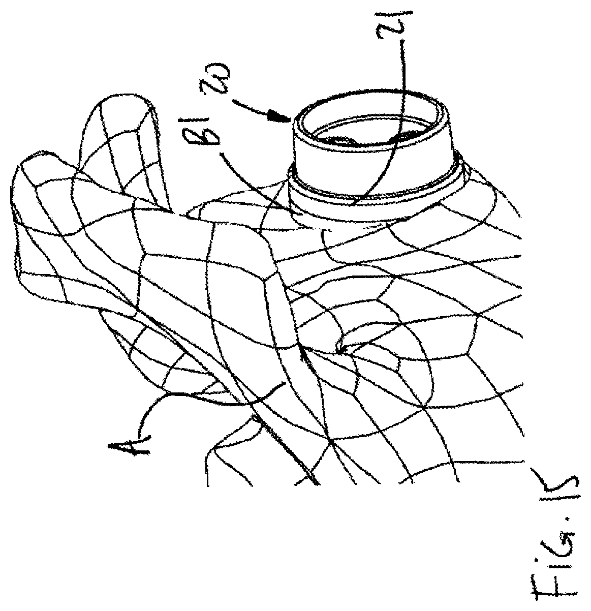
[0047] According to step 12, PSI are generated using the data obtained from the virtual planning. The PSI will be described in further detail hereinafter. Any appropriate manufacturing method and materials may be used for the PSI, provided that the PSI are precise and accurate representations of the PSI required as a result of the virtual planning. The generation of PSI according to step 12 is performed preoperatively using the imagery data that is also used for the step 11 of virtual shoulder surgery planning. Any other source of anatomical data may also be used, such as manual bone measurements, obtained pre-operatively. Another information that may be obtained via the planning step is the generation of a required graft. It may be required to use a graft wedge B1 between the implant and the scapula, and the planning step may therefore define a model of required graft, as shown in FIG. 15, as well as a PSI tool to shape the graft wedge B1 to a predetermined geometry calculated in the virtual planning. The graft wedge B1 would be positioned between the implant 20 and the machined glenoid cavity C. The use of a graft may be required for scapulas limited to a shallow glenoid cavity C, i.e., that does not have a full counterbore shape. Hence, as shown in FIG. 15, the graft wedge B1 would form concurrently with the cavity C the surface against which the implant 20 is applied.
[0048] Steps 13 to 17 are performed intra-operatively. The steps are performed once the shoulder joint has been exposed and the humerus has been dislocated, resected and/or separated from the scapula A (FIG. 2).
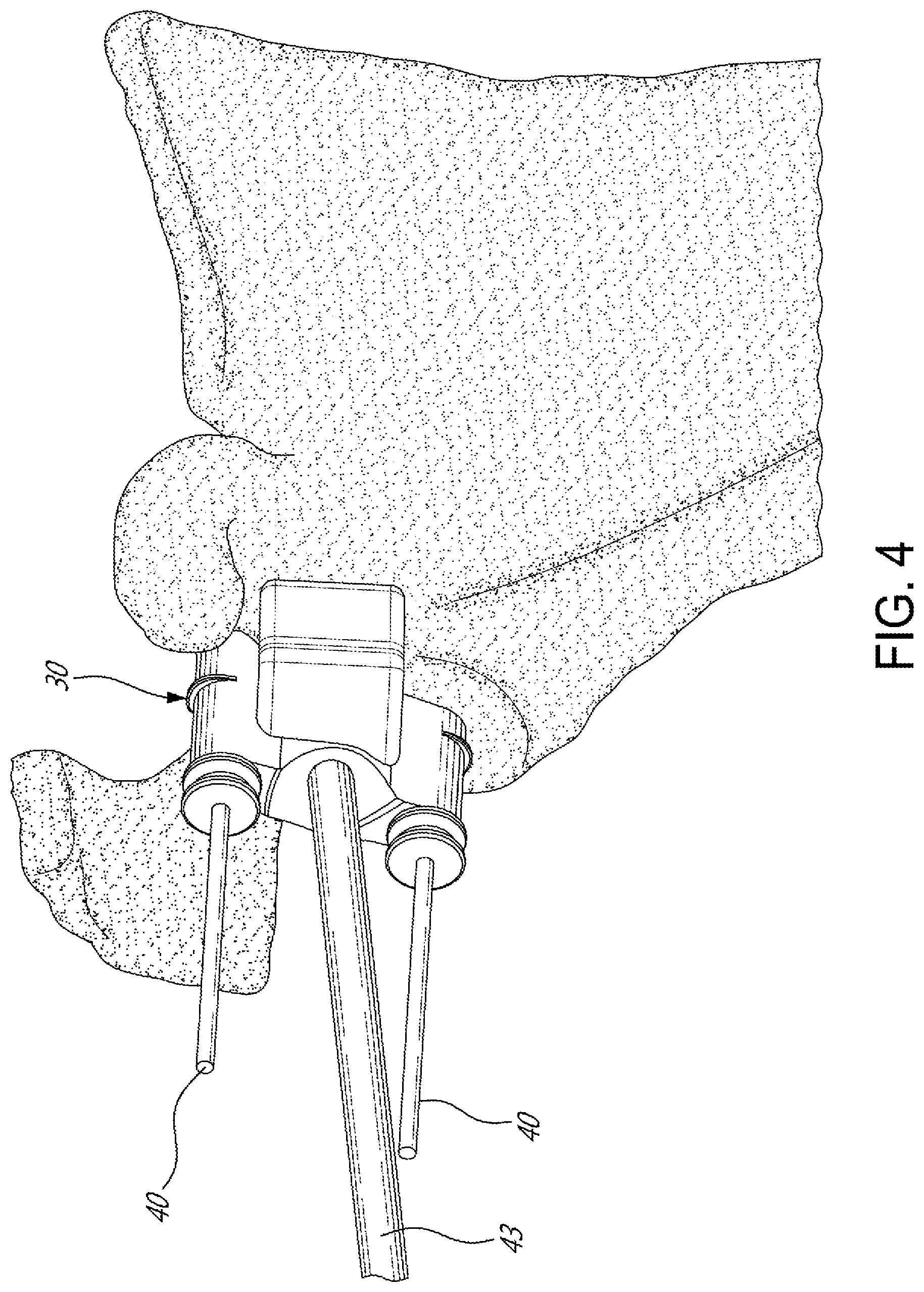
[0049] According to step 13 (FIG. 1), a pair of pins are placed in the scapula A using PSI. Referring concurrently to FIGS. 3 and 4, a pin placement PSI is generally shown at 30. The pin placement PSI 30 comprises an anatomical interface 31. The anatomical interface 31 has a laterally opened hook-like shape so as to receive therein both sides of the scapula head and/or neck of the glenoid B. In accordance with PSI, the anatomical interface 31 has a contact surface(s) 32 that is manufactured to match the corresponding surface on the patient's scapula. Accordingly, the positioning of the pin placement PSI 30 will be guided by the contact surface 32 finding its corresponding matching surface on the scapula A.
[0050] The pin placement PSI 30 further comprises a drill guide 33. The drill guide 33 is positioned relative to the anatomical interface 31 as a function of the virtual planning of step 11 (FIG. 1). The drill guide 33 has a pair of cylindrical cutouts or slots 34 that are specifically positioned and oriented to guide the drilling of the pins in the glenoid B, i.e., the slots 34 extend in the longitudinal direction of the PSI 30. According to an embodiment, lateral openings 35 allow lateral access to the slots 34 such that the pins may be laterally inserted into the slots 34. A socket 36 or like connector may also defined in the drill guide 33 to facilitate the manipulation of the pin placement PSI 30. For instance, an elongated tool may be connected to the pin placement PSI 30 by way of the socket 36, for its distal manipulation.
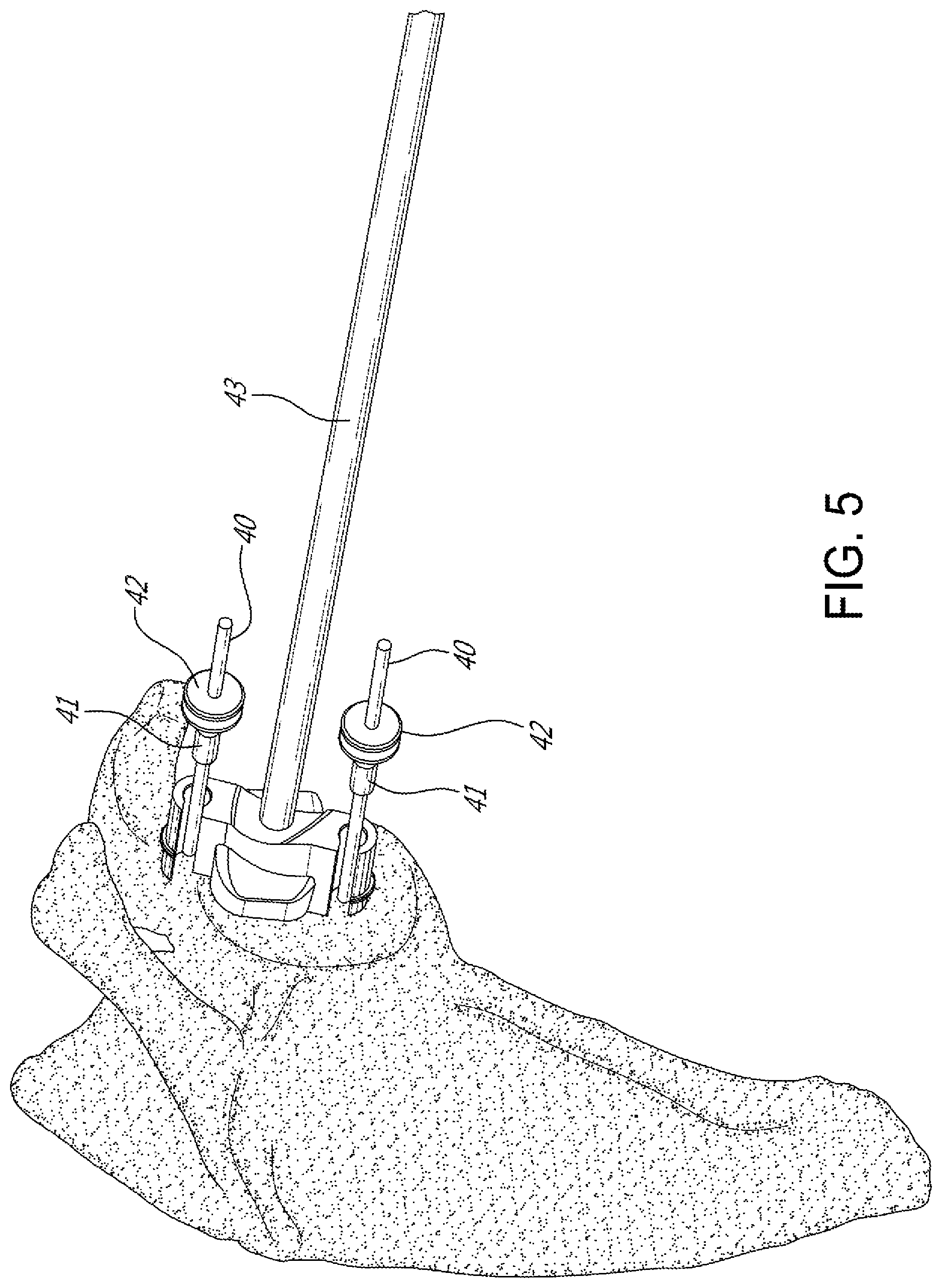
[0051] As shown concurrently in FIGS. 4 and 5, pins 40 are drilled into the scapula A. The pins 40 may be provided with sleeves 41 (a.k.a., bushings) received in a planned fit (e.g., precise fit) that will ensure that the pins 40 are axially centered in the slots 34, as the sleeves 41 have throughbores centered with the slots 34. Moreover, the sleeves 41 may comprise abutment ends 42 to control the depth of insertion of the pins 40 in the glenoid. Any appropriate methods are also considered to control the depth of insertion of the pins 40, such as graduating the pins 40 with a scale, etc.
[0052] In operation, handle 43 is connected to the socket (FIGS. 3 and 4), and the pin placement PSI 30 is installed onto the glenoid B with the anatomical interface 31 ensuring that the pin placement PSI 30 is properly positioned on the scapula A, by laterally moving the pin placement PSI 30 into planned position on the bone. The pins 40 with sleeves 41 thereon are inserted in the slots 34 of the pin placement PSI via the lateral openings 35, and may hence be drilled into the glenoid B, or the sleeves/bushings 41 may be placed in the slots 34 prior to threading the pins 40 therein. Once the pins 40 are suitably inserted in the scapula A, the sleeves 41 may be withdrawn by sliding them off the end of the pins 40 shown in FIG. 5, thereby allowing the removal of the pin placement PSI 30 from the scapula A by a lateral movement. The surfaces of the hook-like portion of the anatomical interface 31 are generally transverse to a longitudinal direction of the drill guide 33. The presence of the lateral openings 35 allows a good contact surface between the hook-like portion of the anatomical interface 31, without having difficulties in the lateral withdrawal of the PSI 30 as the pins 40 pass through the lateral openings 35.
[0053] According to the illustrated embodiment, one of the pins 40 is at a center of the anticipated resurfaced glenoid cavity C, while the other pin 40 is located adjacent to the superior glenoid rim in alignment with the coracoid or at the base of the coracoid. Other positions are also considered. For illustrative purposes, a contemplated position of the pin placement PSI 30 is generally shown relative to the scapula A in FIG. 16.
[0054] Referring to FIG. 1, a step 14 of depth drilling and/or surface reaming on the glenoid B is performed using the pins 40 and an appropriate PSI. Referring concurrently to FIGS. 6 and 7, a reaming PSI is generally shown at 60. The reaming PSI 60 has a first tube 61 with a pin slot 62 that is dimensioned to be slid onto one of the pins 40, thereby forming a cylindrical joint therewith. An end of the first tube 61 defines an abutment 63 to abut against the scapula A. A spacing arm 64 extends laterally from the first tube 61 and has at its free end a second tube 65. The second tube 65 also comprises a shaft slot 66, which shaft slot 66 is laterally accessible via a lateral opening 67, used to rotate the reaming PSI 60 such that the pin 40 enters the shaft slot 66. As the reaming PSI 60 is patient specific, the pin slots 62 and the shaft slot 66 are spaced apart by a predetermined distance to match the spacing between the pins 40. Hence, as shown in FIG. 7, when the first tube 61 is slid onto one of the pins 40, the other pin 40 may be oriented to be within the shaft slot 66 of the second tube 65.
[0055] It is pointed out that step 14 may comprise a verification of the location of the pins 40. As the reaming PSI 60 is fabricated to receive the pins 40, the centrally-located pin 40 should be axially centered in the second tube 65. Any off-centering may indicate improper positioning of the pin 40, and such indication may cause a review of step 13 to reposition the pins 40.
[0056] Referring to FIG. 8, a cannulated reamer 80 may therefore be installed onto the pin 40 that is within the shaft slot 66, so as to be coaxially guided by the pin 40 in translation. The reamer 80 has a reamer end 81 that is selected to perform resurfacing of a planned diameter in the glenoid B. The reamer end 81 is located at the end of a shaft 82. The shaft 82 is sized to be received in the shaft slot 66 of the reaming PSI 60, to form the translational joint. Moreover, the reamer end 81 may also drill a bore of sufficient diameter to receive the peg 22 of the implant 20 therein (FIG. 2), to a depth defined by abutment against the reaming PSI 60. The drilling of the peg bore may alternatively be done separately. Accordingly, the combination of the pin 40 in the cannulated reamer 80 and the cooperation between the shaft 82 and the shaft slot 66 ensures that the glenoid B is reamed specifically where desired to a desired depth. The shaft 82 enters the shaft slot 66 by being slid or snapped into it. Still referring to FIG. 8, a stopper 83 may be installed on the end of the shaft 82. The stopper 83 cooperates with the reaming PSI 60 to limit the depth of penetration of the reamer 80 in the glenoid B, to ensure that the surface reaming and optional depth drilling (if done separately for the peg 22 of FIG. 2) have a planned depth.
[0057] It is observed that both pins 40 are used to support the reaming PSI 60 and guide movement of the cannulated reamer 80. By using both pins 40, the structural integrity of the pin 40/PSI 60 assembly is increased over a single pin 40. However, it is considered to use any other configuration, for instance using a single pin 40, with the cannulated reamer 80, the reamed the glenoid B.
[0058] As shown in FIG. 9, once the glenoid B has been reamed to define the resurfaced glenoid cavity C with peg bore D, the depth drilling PSI 60 may be removed along with the pins 40. Although not shown, it may be desired to keep the pin 40 that is not in the resurfaced glenoid cavity C, as explained hereinafter. In the case in which the wedge graft B1 is used (FIG. 15), the wedge graft B1 is installed at the adequate position on the glenoid B, adjacent to the resurfaced glenoid cavity C. The pin 40 on the coracoid may be used to guide an operator in properly orienting the wedge graft B1. The wedge graft B1 may be fused to the glenoid B, and the screws 23 will secured both the implant 20 and the wedge graft B1 to the glenoid B.
[0059] Referring to FIG. 1, a step 15 of impacting the implant 20 is performed, using one of the pins and PSI for properly orienting the implant 20. More specifically, the orientation of the implant 20 will have an impact on the positioning of the screws 23 (FIG. 2). Hence, in order to replicate the virtual planning of step 11, the implant 20 must be correctly oriented so as to have the throughbores 26 aligned with the planned location of insertion of the screws 23.
[0060] Referring concurrently to FIGS. 10 and 11, an impacting guide PSI is generally shown at 100. The impacting guide PSI 100 comprises a tube 101 with a pin slot 102. The pin slot 102 is sized so as to receive therein the remaining pin 40 and form therewith a cylindrical joint. An abutment end (with any appropriate shape/geometry) 103 of the tube may have a patient-specific contact surface shaped to rest against a surrounding bone surface and hence prevent rotation of the PSI 100 when the tube 101 abuts the bone. An arm 104 projects laterally from the tube 101. A guide bracket 105 is at a free end of the arm 104 and is used to guide the movement of an impactor tool 110. More specifically, the guide bracket 105 has a lateral opening for receiving therein a shaft 111 of the impactor tool 110 to form a sliding joint therewith.
[0061] The impactor tool 110 may be conventional, with a pair of pegs spaced apart to be received in the throughbores of the implant 20 (FIG. 2). The guide bracket 105 is specifically oriented as a function of a location of these pegs at the end of the shaft 111 of the impactor tool 110, to control the positioning of the throughbores 26 of the implant 20, in accordance with the virtual planning step 11 (FIG. 1).
[0062] Hence, with the assembly of FIG. 11, the implant 20 may be inserted into the resurfaced glenoid cavity C. The matching shape of the implant 20 and resurfaced glenoid cavity C may result in a self-centering of the implant 20 during impacting (and therefore not necessitating the patient-specific surface at the abutment end 103 to perform an alignment). However, the PSI 100 and impactor tool 110 generally ensure that the implant 20 is fully inserted in the resurfaced glenoid cavity C, with the throughbores 26 located where planned. At this point, the PSI 100 may be removed with the impactor tool 110 leaving the implant 20 in the resurfaced glenoid cavity C.
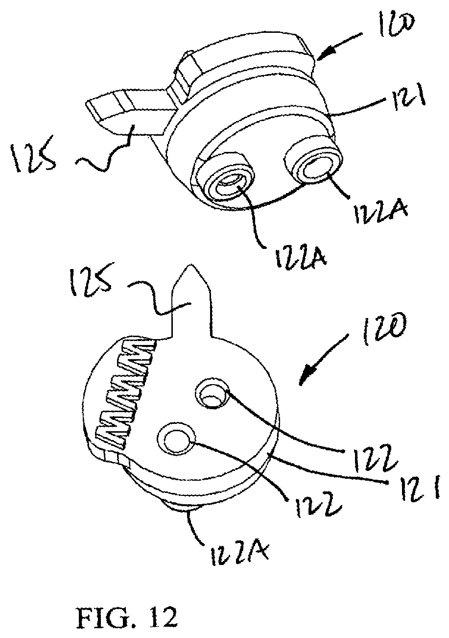
[0063] According to step 16 of FIG. 1, anchor holes may be drilled in the glenoid as planned, for the subsequent insertion of the screws 23. Referring to FIGS. 12 and 13, a drill guide PSI 120 has a body 121 sized to be received in a corresponding cavity in the implant body 25. A pair of drill guide bores 122 are defined in the body 121 of the drill guide PSI 120. The drill guides bores 122 are specifically located and oriented to have guiding cylinders 122A in axial extension of the throughbores 26 in the implant 20 (FIG. 2). Moreover, the diameter of the guiding cylinders 122A is generally tapering to center a drill bit 123 therein, to reduce any potential play between the drill bit 123 and the drill guide bores 122. The material used for the body 121 of the drill guide PSI 120 may also be selected so as not to be damaged by the drill bit 123. As shown in FIG. 13, a stopper 124 may be provided on the drill bit 123 to control the drilling depth to reach the planned depth for the anchor holes. Alternative methods are considered as well, such as graduating the drill bit 123 with a scale, to control the depth. Once the anchor holes have been drilled, the drill guide PSI 120 may be removed. As shown in FIG. 12, the drill guide PSI 120 may also comprise a visual pointer 125. The visual pointer 125 may be patient-specifically formed in the drill guide PSI 120 to point at the remaining pin. This therefore represents an additional verification step to ensure that the holes are drilled at the desired location.
[0064] According to step 17 of FIG. 1, screws 23 (or like fasteners) may secure the implant 20 to the scapula A, replicating the virtual planning of FIG. 2. Conventional steps are then performed to finalize the shoulder surgery.
[0065] It is pointed out that the method 10 may include a step of creating the graft B1 of FIG. 15. The step of method 10 may include providing a PSI tool for the removal of bone material, for instance from the humerus, as the humerus must be resurfaced. However, the graft B1 removed from the humerus or other bone may simply have a cylindrical shape, and hence a standard cylindrical reamer of appropriate diameter may be used. As the graft B1 is shown as having a wedge shape in FIG. 15, an appropriate PSI tool may be created to machine the oblique plane of the graft B1.
[0066] While the methods and systems described above have been described and shown with reference to particular steps performed in a particular order, these steps may be combined, subdivided or reordered to form an equivalent method without departing from the teachings of the present disclosure. Accordingly, the order and grouping of the steps is not a limitation of the present disclosure.
* * * * *
D00000
D00001
D00002
D00003
D00004
D00005
D00006
D00007
D00008
D00009
D00010
D00011
D00012
D00013

D00014

D00015
D00016

XML
uspto.report is an independent third-party trademark research tool that is not affiliated, endorsed, or sponsored by the United States Patent and Trademark Office (USPTO) or any other governmental organization. The information provided by uspto.report is based on publicly available data at the time of writing and is intended for informational purposes only.
While we strive to provide accurate and up-to-date information, we do not guarantee the accuracy, completeness, reliability, or suitability of the information displayed on this site. The use of this site is at your own risk. Any reliance you place on such information is therefore strictly at your own risk.
All official trademark data, including owner information, should be verified by visiting the official USPTO website at www.uspto.gov. This site is not intended to replace professional legal advice and should not be used as a substitute for consulting with a legal professional who is knowledgeable about trademark law.