Devices And Methods For Cloud-based Sidelink Scheduling And Base Station Interface Therefor
AYAZ; Serkan ; et al.
U.S. patent application number 16/700683 was filed with the patent office on 2020-04-30 for devices and methods for cloud-based sidelink scheduling and base station interface therefor. The applicant listed for this patent is Huawei Technologies Co., Ltd.. Invention is credited to Serkan AYAZ, Prajwal KESHAVAMURTHY, Daniel MEDINA, Chan ZHOU.
| Application Number | 20200137814 16/700683 |
| Document ID | / |
| Family ID | 59227691 |
| Filed Date | 2020-04-30 |


| United States Patent Application | 20200137814 |
| Kind Code | A1 |
| AYAZ; Serkan ; et al. | April 30, 2020 |
DEVICES AND METHODS FOR CLOUD-BASED SIDELINK SCHEDULING AND BASE STATION INTERFACE THEREFOR
Abstract
The present invention relates to a network entity (110), in particular a cloud server (110), comprising a processor (110a) being configured to control radio resources, in particular sidelink radio resources, on behalf of one or more, in particular two, mobile networks (PLMNs) (120, 130). Moreover, the invention relates to a base station (BS) (123, 133) of a PLMN (120, 130), comprising a processor (133a) configured to process control plane information related to control of radio resources, in particular sidelink radio resources, and a communication interface (133b) configured to transmit and/or receive to/from the network entity (110) said control plane information.
| Inventors: | AYAZ; Serkan; (Munich, DE) ; MEDINA; Daniel; (Munich, DE) ; KESHAVAMURTHY; Prajwal; (Munich, DE) ; ZHOU; Chan; (Munich, DE) | ||||||||||
| Applicant: |
|
||||||||||
|---|---|---|---|---|---|---|---|---|---|---|---|
| Family ID: | 59227691 | ||||||||||
| Appl. No.: | 16/700683 | ||||||||||
| Filed: | December 2, 2019 |
Related U.S. Patent Documents
| Application Number | Filing Date | Patent Number | ||
|---|---|---|---|---|
| PCT/EP2017/082688 | Dec 13, 2017 | |||
| 16700683 | ||||
| Current U.S. Class: | 1/1 |
| Current CPC Class: | H04W 76/27 20180201; H04W 92/18 20130101; H04W 88/04 20130101; H04W 72/02 20130101; H04L 2212/00 20130101; H04W 76/00 20130101; H04W 84/042 20130101; H04W 8/005 20130101; H04W 72/1278 20130101; H04W 76/14 20180201; H04W 4/40 20180201; H04W 72/1205 20130101 |
| International Class: | H04W 76/14 20060101 H04W076/14; H04W 88/04 20060101 H04W088/04; H04W 72/02 20060101 H04W072/02; H04W 8/00 20060101 H04W008/00; H04W 76/27 20060101 H04W076/27; H04W 72/12 20060101 H04W072/12 |
Foreign Application Data
| Date | Code | Application Number |
|---|---|---|
| May 30, 2017 | EP | PCT/EP2017/063050 |
Claims
1. A network entity, in particular a cloud server, comprising a processor being configured to control radio resources, in particular sidelink radio resources, on behalf of one or more, in particular two, mobile networks (PLMNs).
2. The network entity of claim 1, wherein the processor is configured to control sidelink radio resources for transmission by at least one of a first user equipment (UE) of a first PLMN and a second UE of a second PLMN.
3. The network entity of claim 1, wherein the processor is configured to at least one of: perform at least one of dynamic and semi-persistent scheduling of sidelink transmissions by allocating one or more sidelink radio resources to at least one of a first UE of the first PLMN and a second UE of the second PLMN; and set the value of one or more sidelink radio interface configuration parameters for at least one of the first UE of the first PLMN and the second UE of the second PLMN.
4. The network entity of claim 1, wherein the radio resources are located on a same carrier.
5. The network entity of claim 1, comprising a communication interface for communication with at least one of a first base station (BS) of the first PLMN and a second BS of the second PLMN.
6. The network entity according to claim 1, wherein the communication interface is configured to at least one of: transmit scheduling information to the first BS, wherein the scheduling information specifies one or more sidelink radio resources allocated to the first UE for transmission of at least one of sidelink control information and sidelink user data; and transmit scheduling information to the second BS, wherein the scheduling information specifies one or more sidelink radio resources allocated to the second UE for transmission of at least one of sidelink control information and sidelink user data.
7. The network entity of claim 1, wherein the scheduling information comprises one or more of the following: a carrier indicator; a location of the one or more sidelink radio resources in the time domain; a location of the one or more sidelink radio resources in the frequency domain; a retransmission related parameter; a semi-persistent scheduling (SPS) related parameter.
8. The network entity of claim 5, wherein the communication interface is configured to at least one of: transmit the one or more sidelink radio interface configuration parameters for the first UE to the first BS; and transmit the one or more sidelink radio interface configuration parameters for the second UE to the second BS.
9. The network entity of claim 1, wherein the one or more sidelink radio interface configuration parameters comprise one or more radio resource control (RRC) parameters controlling the operation of at least one of the medium access control (MAC) layer and the physical (PHY) layer for sidelink communication.
10. The network entity of claim 9, wherein the one or more radio resource control (RRC) parameters controlling the operation of at least one of the medium access control (MAC) layer and the physical (PHY) layer for sidelink communication comprise one or more of the following: a radio resource pool configuration parameter; a zone configuration parameter; a radio resource selection configuration parameter; a semi-persistent scheduling (SPS) configuration parameter; a measurement configuration parameter.
11. The network entity of claim 5, wherein the communication interface is further configured to receive from at least one of the first BS and the second BS at least one of one or more sidelink radio resource request parameters and one or more measurements.
12. The network entity of claim 1, wherein the one or more sidelink radio resource request parameters comprise one or more of the following: a carrier frequency for at least one of transmitting and receiving by a UE; a destination ID; a parameter for semi-persistent scheduling (SPS), in particular periodicity, timing offset, at least one of priority and message size; and/or wherein the one or more measurements comprise one or more of the following: a geographic location of a UE; a received signal strength in one or more radio resources; a sidelink buffer status.
13. A base station (BS) of a PLMN, comprising a processor configured to process control plane information related to control of radio resources, in particular sidelink radio resources, and a communication interface configured to at least one of transmit and receive to/from a network entity, in particular a cloud server, said control plane information.
14. The base station of claim 13, wherein the communication interface is configured to transmit to the network entity at least one of one or more sidelink radio resource request parameters and one or more measurements.
15. The base station of claim 13, wherein the one or more sidelink radio resource request parameters comprise one or more of the following: a carrier frequency for at least one of transmitting and receiving by a UE; a destination ID; a parameter for semi-persistent scheduling, in particular periodicity, timing offset, at least one of priority and message size; and/or wherein the one or more measurements comprise one or more of the following: a geographic location of a UE; a received signal strength in one or more radio resources; a sidelink buffer status.
16. The base station of claim 13, wherein the communication interface is configured to receive from the network entity scheduling information, wherein the scheduling information specifies one or more sidelink radio resources allocated to a UE for transmission of at least one of sidelink control information and sidelink user data.
17. The base station of claim 13, wherein the scheduling information comprises one or more of the following: a carrier indicator; a location of the one or more sidelink radio resources in the time domain; a location of the one or more sidelink radio resources in the frequency domain; a retransmission related parameter; a semi-persistent scheduling (SPS) related parameter.
18. The base station of claim 13, wherein the communication interface is configured to receive from the network entity one or more sidelink radio interface configuration parameters for a UE.
19. The base station of claim 13, wherein the one or more sidelink radio interface configuration parameters comprise one or more radio resource control (RRC) parameters controlling the operation of at least one of the medium access control (MAC) layer and the physical (PHY) layer for sidelink communication.
20. The base station of claim 13, wherein the one or more radio resource control (RRC) parameters controlling the operation of at least one of the medium access control (MAC) layer and the physical (PHY) layer for sidelink communication comprise one or more of the following: a radio resource pool configuration parameter; a zone configuration parameter; a radio resource selection configuration parameter; a semi-persistent scheduling (SPS) configuration parameter; a measurement configuration parameter.
Description
CROSS-REFERENCE TO RELATED APPLICATIONS
[0001] This application is a continuation of International Application No. PCT/EP2017/082688, filed on Dec. 13, 2017, which claims priority to International Patent Application No. PCT/EP2017/063050, filed on May 30, 2017. The disclosures of the aforementioned applications are hereby incorporated by reference in their entireties.
TECHNICAL FIELD
[0002] In general, the present invention relates to the field of wireless communication. In particular, the invention relates to devices and methods for PLMN operator independent management of V2X sidelink communication.
BACKGROUND
[0003] In 3GPP (3rd Generation Partnership Project) cellular networks--such as LTE (Long Term Evolution) or 5G--supporting V2X (Vehicle-to-Everything) sidelink communication, sidelink (SL) radio resources are generally controlled by a Public Land Mobile Network (PLMN) operator. User equipments (UEs) belonging to different PLMN operators are assumed to transmit using different spectral bands (i.e., different carrier frequencies). However, this precludes the possibility of spectrum sharing among operators. For some safety-of-life applications, the future spectrum allocation for V2X sidelink communication may not belong to a specific operator, but rather be shared by multiple operators.
[0004] There are two modes of operation for V2X communication in 3GPP Rel-14, namely over the PC5 (sidelink) interface and over the LTE-Uu (uplink/downlink) interface. In the sidelink mode of operation, which is referred to as V2X sidelink communication, the user equipments (UEs) can communicate with each other directly over the PC5 interface.
[0005] Generally, a UE supporting V2X sidelink communication can operate in two modes for resource allocation.
[0006] In the first resource allocation mode, which is referred to as scheduled resource allocation or sidelink transmission mode 3, the UE requests transmission resources from a base station (BS), and the BS schedules dedicated resources to the UE for transmission of sidelink control information (SCI) and sidelink user data.
[0007] In the second resource allocation mode, which is referred to as UE autonomous resource selection or sidelink transmission mode 4, the UE on its own selects resources from resource pools to transmit SCI and data.
[0008] In order to prevent interference among V2X sidelink transmissions in the second operation mode, 3GPP Radio Resource Control (RRC) specifications introduce two features in Release 14, namely "zones" and "sensing". The world is divided into geographical zones. A zone is a periodically repeating geographic region. The UE selects a radio resource pool based on the zone it is located in. Based on channel sensing within the selected radio resource pool, the UE selects specific sidelink radio resources for transmission and may reserve periodically recurring (i.e., semi-persistent) sidelink radio resources.
[0009] Different operators use different V2X sidelink configurations (e.g., radio resource pools, zones, etc.) specified in sl-V2X-ConfigCommon, sl-V2X-ConfigDedicated, etc. If UEs belonging to different operators transmit on the same carrier frequency without a common configuration, then UEs in different zones may select the same resource pool, leading to inter-zone interference.
[0010] In the scheduled resource allocation mode, the sidelink scheduler at the BS uses UE geographical location information (e.g., obtained from periodic position reports) to ensure orthogonal time/frequency resources are allocated to nearby UEs, thus preventing interference. Each operator, however, has its own sidelink scheduler, and is unaware of UEs belonging to other operators (including their geographical location). If nearby UEs belonging to different operators transmit on the same carrier frequency, the operator-centric sidelink schedulers won't be able to prevent interference.
[0011] Thus, there is a need for improved devices and methods for managing V2X sidelink communication in a PLMN operator independent manner.
SUMMARY
[0012] It is an object of the invention to provide for improved devices and methods for managing V2X sidelink communication in a PLMN operator independent manner.
[0013] The foregoing and other objects are achieved by the subject matter of the independent claims. Further implementation forms are apparent from the dependent claims, the description and the figures.
[0014] Generally, embodiments of the invention are based on the idea of moving the intelligence (control of sidelink radio resources, including sidelink scheduling) from the operator's radio access network (RAN) to a network entity accessible by different operators, while keeping the standard interface (RRC/MAC/PHY control signaling messages) between a base station (BS) and a user equipment (UE) unmodified, so as to have no impact on the UE architecture. The UE is thus unaware that the sidelink radio resources are being controlled by a network entity located, for instance, in the cloud and not in the operator's RAN. In embodiments of the invention, a network entity, in particular a cloud server, communicates with an operator's BS via a new interface to control the configuration parameters of the BS for V2X sidelink communication. The BS and UE exchange control signaling related to V2X sidelink communication as usual via the standard interface specified by 3GPP. Thus, the UE is unaware that sidelink radio resources are controlled from outside the RAN. A key advantage provided by embodiments of the invention is that no changes to the current 3GPP Rel-14 UE architecture are required, thus having no impact on the UE.
[0015] More specifically, according to a first aspect, the invention relates to a network entity, in particular a cloud server, comprising a processor being configured to control radio resources, in particular sidelink radio resources, on behalf of one or more, in particular two, mobile networks (PLMNs). A cloud server in the meaning of the invention is an entity that is configured to communicate with entities of a PLMN, but may or may not be itself part of a PLMN, i.e., it may or may not be related to a PLMN ID. A PLMN is a Public Land Mobile Network, which is run by a certain operator. In particular, a PLMN can be identified by a PLMN ID, wherein the PLMN ID can be a unique identifier of the PLMN in a relevant area.
[0016] In a further implementation form of the first aspect, the processor is configured to control sidelink radio resources for transmission by a first UE of a first PLMN and/or a second UE of a second PLMN.
[0017] In a further implementation form of the first aspect, the processor is configured to perform dynamic and/or semi-persistent scheduling of sidelink transmissions by allocating one or more sidelink radio resources to a first UE of the first PLMN and/or to a second UE of the second PLMN; and/or set the value of one or more sidelink radio interface configuration parameters for the first UE of the first PLMN and/or for the second UE of the second PLMN.
[0018] In a further implementation form of the first aspect, the radio resources are located on a same carrier.
[0019] In a further implementation form of the first aspect, the network entity further comprises a communication interface for communication with a first base station (BS) of the first PLMN and/or a second BS of the second PLMN.
[0020] In a further implementation form of the first aspect, the communication interface is configured to transmit scheduling information to the first BS, wherein the scheduling information specifies one or more sidelink radio resources allocated to the first UE for transmission of sidelink control information and/or sidelink user data; and/or transmit scheduling information to the second BS, wherein the scheduling information specifies one or more sidelink radio resources allocated to the second UE for transmission of sidelink control information and/or sidelink user data.
[0021] In case the network entity is configured to transmit scheduling information to the first and to the second BS, this scheduling information need not be the same scheduling information.
[0022] In a further implementation form of the first aspect, the scheduling information comprises one or more of the following: [0023] a carrier indicator; [0024] a location of the one or more sidelink radio resources in the time domain; [0025] a location of the one or more sidelink radio resources in the frequency domain; [0026] a retransmission related parameter; [0027] a semi-persistent scheduling (SPS) related parameter.
[0028] In a further implementation form of the first aspect, the communication interface is configured to transmit the one or more sidelink radio interface configuration parameters for the first UE to the first BS; and/or transmit the one or more sidelink radio interface configuration parameters for the second UE to the second BS.
[0029] In a further implementation form of the first aspect, the one or more sidelink radio interface configuration parameters comprise one or more radio resource control (RRC) parameters controlling the operation of the medium access control (MAC) layer and/or the physical (PHY) layer for sidelink communication.
[0030] In a further implementation form of the first aspect, the one or more radio resource control (RRC) parameters controlling the operation of the medium access control (MAC) layer and/or the physical (PHY) layer for sidelink communication comprise one or more of the following: [0031] a radio resource pool configuration parameter; [0032] a zone configuration parameter; [0033] a radio resource selection configuration parameter; [0034] a semi-persistent scheduling (SPS) configuration parameter; [0035] a measurement configuration parameter.
[0036] In a further implementation form of the first aspect, the communication interface is further configured to receive from the first BS and/or from the second BS one or more sidelink radio resource request parameters and/or one or more measurements.
[0037] In a further implementation form of the first aspect, the one or more sidelink radio resource request parameters comprise one or more of the following: [0038] a carrier frequency for transmitting and/or receiving by a UE; [0039] a destination ID; [0040] a parameter for semi-persistent scheduling (SPS), in particular periodicity, timing offset, priority and/or message size; and the one or more measurements comprise one or more of the following: [0041] a geographic location of a UE; [0042] a received signal strength in one or more radio resources; [0043] a sidelink buffer status.
[0044] According to a second aspect, the invention relates to a corresponding method for operating a network entity, in particular a cloud server, comprising the step of controlling radio resources, in particular sidelink radio resources, on behalf of one or more, in particular two, mobile networks (PLMNs).
[0045] The method according to the second aspect of the invention can be performed by the network entity according to the first aspect of the invention. Further features of the method according to the second aspect of the invention result directly from the functionality of the network entity according to the first aspect of the invention and its different implementation forms.
[0046] According to a third aspect, the invention relates to a base station (BS) of a PLMN, comprising a processor configured to process control plane information related to control of radio resources, in particular sidelink radio resources, and a communication interface configured to transmit and/or receive to/from a network entity, in particular a cloud server, said control plane information.
[0047] In a further implementation form of the third aspect, the communication interface is configured to transmit to the network entity one or more sidelink radio resource request parameters and/or one or more measurements.
[0048] In a further implementation form of the third aspect, the one or more sidelink radio resource request parameters comprise one or more of the following: [0049] a carrier frequency for transmitting and/or receiving by a UE; [0050] a destination ID; [0051] a parameter for semi-persistent scheduling (SPS), in particular periodicity, timing offset, priority and/or message size; and the one or more measurements comprise one or more of the following: [0052] a geographic location of a UE; [0053] a received signal strength in one or more radio resources; [0054] a sidelink buffer status.
[0055] In a further implementation form of the third aspect, the communication interface is configured to receive from the network entity scheduling information, wherein the scheduling information specifies one or more sidelink radio resources allocated to a UE for transmission of sidelink control information and/or sidelink user data.
[0056] In a further implementation form of the third aspect, the scheduling information comprises one or more of the following: [0057] a carrier indicator; [0058] a location of the one or more sidelink radio resources in the time domain; [0059] a location of the one or more sidelink radio resources in the frequency domain; [0060] a retransmission related parameter; [0061] a semi-persistent scheduling (SPS) related parameter.
[0062] In a further implementation form of the third aspect, the communication interface is configured to receive from the network entity one or more sidelink radio interface configuration parameters for a UE.
[0063] In a further implementation form of the third aspect, the one or more sidelink radio interface configuration parameters comprise one or more radio resource control (RRC) parameters controlling the operation of the medium access control (MAC) layer and/or the physical (PHY) layer for sidelink communication.
[0064] In a further implementation form of the third aspect, the one or more radio resource control (RRC) parameters controlling the operation of the medium access control (MAC) layer and/or the physical (PHY) layer for sidelink communication comprise one or more of the following: [0065] a radio resource pool configuration parameter; [0066] a zone configuration parameter; [0067] a radio resource selection configuration parameter; [0068] a semi-persistent scheduling (SPS) configuration parameter; [0069] a measurement configuration parameter.
[0070] According to a fourth aspect, the invention relates to a corresponding method for operating a base station (BS) of a PLMN, comprising a communication interface configured to transmit and/or receive to/from a network entity, in particular a cloud server, control plane information related to control of radio resources, in particular sidelink radio resources.
[0071] The method according to the fourth aspect of the invention can be performed by the base station according to the third aspect of the invention. Further features of the method according to the fourth aspect of the invention result directly from the functionality of the base station according to the third aspect of the invention and its different implementation forms.
[0072] According to a fifth aspect, the invention relates to a computer program comprising program code for performing the method of the second aspect or the method of the fourth aspect when executed on a computer or a processor.
[0073] The invention can be implemented in hardware and/or software.
BRIEF DESCRIPTION OF DRAWINGS
[0074] Further embodiments of the invention will be described with respect to the following figures, wherein:
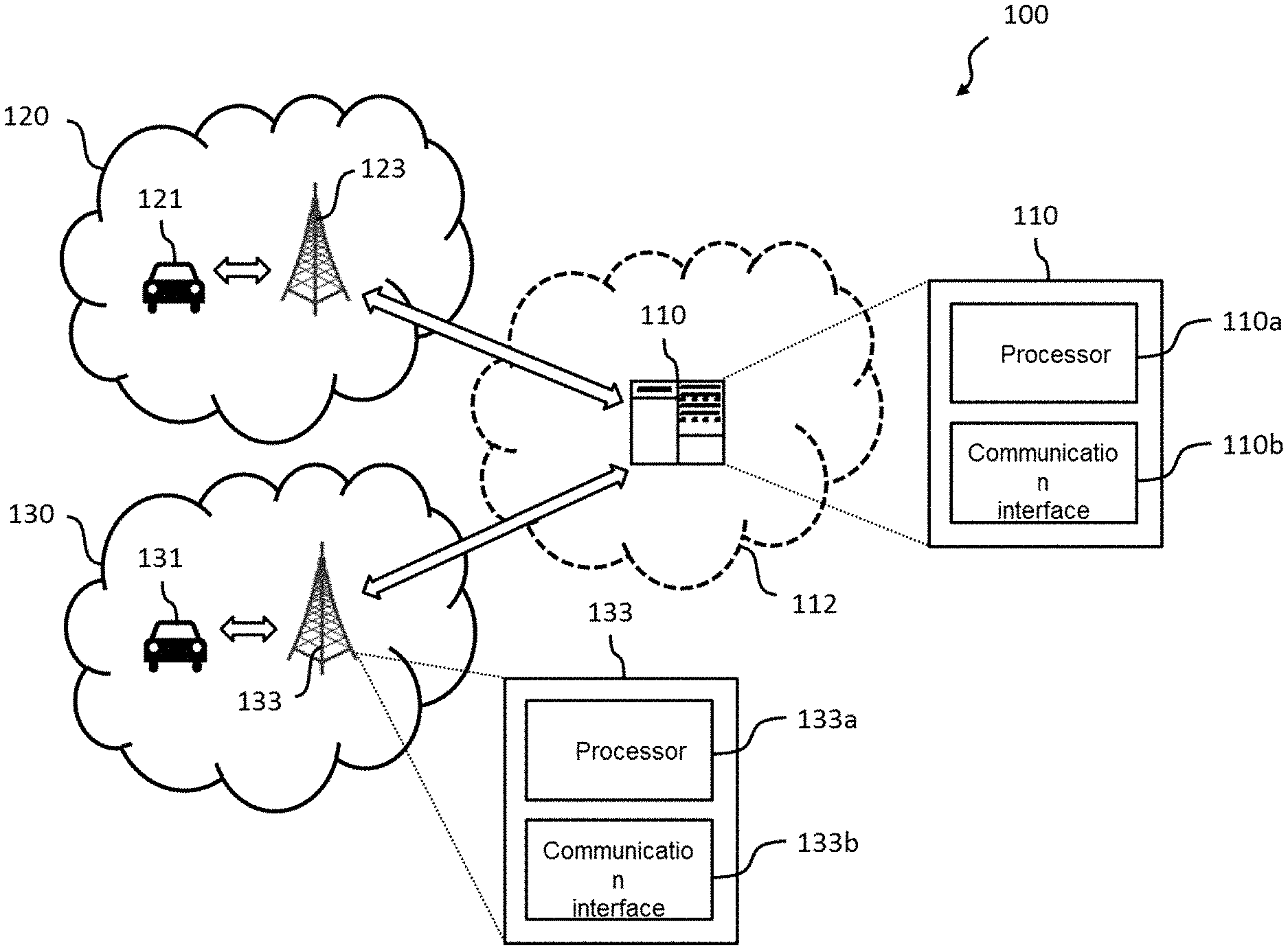
[0075] FIG. 1 shows a schematic diagram illustrating a V2X communication system including a network entity according to an embodiment and a base station according to an embodiment;
[0076] FIG. 2 shows adjacent PSCCH (Physical Sidelink Control Channel) and PSSCH (Physical Sidelink Shared Channel) radio resources in an exemplary grid of sidelink radio resources; and
[0077] FIG. 3 shows a schematic diagram illustrating some further aspects of the V2X communication system of FIG. 1.
[0078] In the various figures, identical reference signs will be used for identical or at least functionally equivalent features.
DESCRIPTION OF EMBODIMENTS
[0079] In the following description, reference is made to the accompanying drawings, which form part of the disclosure, and in which are shown, by way of illustration, specific aspects in which the present invention may be placed. It is understood that other aspects may be utilized and structural or logical changes may be made without departing from the scope of the present invention. The following detailed description, therefore, is not to be taken in a limiting sense, as the scope of the present invention is defined by the appended claims.
[0080] For instance, it is understood that a disclosure in connection with a described method may also hold true for a corresponding device or system configured to perform the method and vice versa. For example, if a specific method step is described, a corresponding device may include a unit to perform the described method step, even if such unit is not explicitly described or illustrated in the figures. Further, it is understood that the features of the various exemplary aspects described herein may be combined with each other, unless specifically noted otherwise.
[0081] FIG. 1 illustrates a V2X communication system 100 including a network entity 110 according to an embodiment. As can be taken from the detailed view of FIG. 1 and as will be explained in more detail further below, the network entity 110, which in the embodiment shown in FIG. 1 is implemented as a single cloud server 110 located in the Internet 112, comprises a processor 110a being configured to control radio resources, in particular sidelink radio resources, on behalf of one or more mobile networks (PLMNs) 120, 130. In the embodiment shown in FIG. 1, the processor 110a of the cloud server 110 is configured to control sidelink radio resources for transmission by a first user equipment (UE) 121 of a first PLMN 120 and a second UE 131 of a second PLMN 130. As used herein, a PLMN is a Public Land Mobile Network, which is run by a certain operator. In particular, a PLMN can be identified by a PLMN ID, wherein the PLMN ID can be a unique identifier of the PLMN in a relevant area.
[0082] As can be taken from the detailed view shown in FIG. 1, the network entity 110 further comprises a communication interface 110b, which is configured to communicate with a first base station (BS) 123 of the first PLMN 120 and a second BS 133 of the second PLMN 130. Likewise, the first BS 123 and the second BS 133 each comprise a processor (e.g. the processor 133a of the BS 133 shown in FIG. 1) configured to process control plane information related to control of sidelink radio resources, and a communication interface (e.g. the communication interface 133b of the BS 133 shown in FIG. 1) configured to communicate with the network entity 110. As illustrated in the exemplary embodiment shown in FIG. 1, the first UE 121 and second UE 131 could be implemented as part of a respective vehicle, such as in the form of an on-board unit. As will be appreciated, however, the first UE 121 and second UE 131 could be implemented as mobile phones or other types of user equipments as well.
[0083] As will be described in more detail further below, the communication interface 133b of the respective BS 123, 133 is configured to transmit and/or receive to/from the network entity 110 control plane information related to the control of radio resources, in particular sidelink radio resources.
[0084] Before describing in more detail further embodiments of the invention, in the following some further technical background will be provided, which can be helpful for understanding different aspects of the present invention.
[0085] In an embodiment, the UEs 121, 131 supporting V2X sidelink communication can operate in two modes for resource allocation.
[0086] In the first resource allocation mode, which is referred to as scheduled resource allocation, the UE 121, 131 requests transmission resources from a base station 123, 133, and the base station schedules dedicated resources to the UE for transmission of sidelink control information (SCI) and sidelink user data.
[0087] In the second resource allocation mode, which is referred to as UE autonomous resource selection, the UE 121, 131 on its own selects resources from resource pools to transmit SCI and data. The UE 121, 131 selects a resource pool based on the zone the UE 121, 131 is located in. Based on sensing, the UE 121, 131 can select specific sidelink resources and may reserve periodically recurring (i.e., semi-persistent) sidelink resources.
[0088] The UE 121, 131 may report geographical location information to the respective base station 123, 133. The UE 121, 131 can be configured to report the complete UE geographical location information based on periodic reporting.
[0089] Geographical zones can be configured by the respective base station 123, 133 (e.g., SystemInformationBlockType21) or preconfigured (e.g., SL-V2X-Preconfiguration). When zones are configured, the world is divided into geographical zones using a single fixed reference point, zone length and zone width, from which the UE 121, 131 determines the identity of the zone it is located in.
[0090] In the following, a summary of radio resource control (RRC) related procedures for V2X sidelink communication is provided, which are relevant for embodiments of the invention.
[0091] The information element (IE) SystemInformationBlockType21 can contain the following common configuration information related to V2X sidelink communication (i.e., sl-V2X-ConfigCommon): v2x-CommTxPoolNormalCommon (list of up to 8 transmit resource pools for normal conditions for transmission in RRC IDLE); v2x-CommTxPoolExceptional (one transmit resource pool for exceptional conditions (e.g., handover)); v2x-CommRxPool (list of up to 16 receive resource pools); v2x-SyncConfig (synchronization configuration for Sidelink Synchronization Signal (SLSS) transmission); v2x-InterFreqInfoList (list of up to 8 possible carrier frequencies for V2X sidelink communication); v2x-ResourceSelectionConfig (sensing configuration for UE autonomous resource selection); and zoneConfig (zone configuration (length, width, etc.)).
[0092] Moreover, the v2x-ResourceSelectionConfig includes: probResourceKeep (probability with which the UE keeps the current resource at the end of a resource reselection period); pssch-TxConfigList (a list of up to 16 SL-PSSCH-TxConfig configurations, including synchronization reference type (typeTxSync: gnss, enb, ue); and PSSCH transmission parameters (minMCS-PSSCH, maxMCS-PSSCH, minRB-NumberPSSCH, maxRB-NumberPSSCH, allowedRetxNumberPSSCH), restrictResourceReservationPeriodList (list of up to 16 values allowed for the resource reservation interval), and thresPSSCH-RSRP-List (list of 64 threshold values used when excluding resources).
[0093] In an embodiment, the IE SL-CommResourcePoolV2X specifies parameters for a specific resource pool, including: sl-Subframe (the bitmap used to determine the subframes belonging to the resource pool); adjacencyPSCCH-PSSCH (whether a UE 121, 131 shall transmit PSCCH and PSSCH in adjacent physical resource blocks (PRBs)); sizeSubchannel (number of PRBs of each subchannel in the corresponding resource pool); numSubchannel (number of subchannels in the corresponding resource pool); startRB-Subchannel (lowest PRB index of the subchannel with the lowest index); startRB-PSCCH-Pool (lowest PRB index of the PSCCH pool); dataTxParameters (parameters for sidelink power control); and zoneID (zone identity for which the UE 121, 131 shall use this resource pool).
[0094] When the UE 121, 131 receives RRCConnectionReconfiguration including sl-V2X-ConfigDedicated, it can perform the following dedicated configuration procedure.
[0095] If the field commTxResources is set to scheduled, the UE 121, 131 requests the base station to assign transmission resources based on sidelink Buffer Status Reports (Sidelink BSR) from the UE 121, 131. The field commTxResources also specifies the resource pool (v2x-SchedulingPool) and modulation and coding scheme (mcs) to be used by the UE 121, 131. Within the allocated pool, the specific resources for PSSCH transmission are determined based on the content of the SL Grant received via Downlink Control Information (DCI format 5A) on PDCCH (Physical Downlink Control Channel).
[0096] If the field commTxResources is set to ue-Selected, the UE 121, 131 transmits V2X sidelink data based on sensing using one of the resource pools indicated by v2x-commTxPoolNormalDedicated. The sensing configuration is specified in v2x-CommTxPoolSensingConfig.
[0097] In scheduled mode, if semi-persistent scheduling (SPS) is enabled, an sl-V-SPS-RNTI is included in the field SPS-Config within the IE radioResourceConfigDedicated sent via the RRCConnectionReconfiguration message. Each SL SPS configuration SPS-ConfigSL is specified by the following parameters: sps-ConfigIndex indicates the index of the SL SPS configuration; semiPersistSchedIntervalSL indicates the time interval between consecutive transmission opportunities (20 ms, 50 ms, 100 ms, 200 ms, 300 ms, 400 ms, 500 ms, 600 ms, 700 ms, 800 ms, 900 ms, 1000 ms).
[0098] A UEAssistanceInformation message can be used for the indication of UE assistance information to the respective base station 123, 133. This message includes sps-AssistanceInformation to assist the base station to configure SPS, e.g., by providing the traffic characteristics (periodicity, timing offset, priority, message size, etc.) of sidelink logical channel(s) (trafficPatternInfoListSL).
[0099] In an embodiment, an RRC_CONNECTED UE 121, 131 sends a SidelinkUEInformation message to the respective serving base station 123, 133 in order to request assignment of dedicated sidelink resources. The SidelinkUEInformation message can include the following information: v2x-CommRxInterestedFreq indicates the index of the frequency (in v2x-InterFreqInfoList broadcast in SystemInformationBlockType21) on which the UE is interested to receive V2X sidelink communication. The V2X sidelink communication transmission resource request (v2x-CommTxResourceReq) includes: v2x-CommTxFreq indicating the index of the frequency on which the UE is interested to transmit V2X sidelink communication (same value as indicated in v2x-CommRxInterestedFreq); and v2x-DestinationInfoList containing a list of up to 16 Destination Layer-2 IDs for V2X sidelink communication.
[0100] In an embodiment, if the respective UE 121, 131 is in coverage and has V2X sidelink data to be transmitted, it operates in one of the following ways.
[0101] If the UE 121, 131 is in RRC_CONNECTED and the field commTxResources is set to scheduled, it requests the base station to assign dedicated resources for transmission. If commTxResources is set to ue-Selected, the UE transmits based on sensing using one of the resource pools indicated by v2x-commTxPoolNormalDedicated.
[0102] If the UE 121, 131 is in RRC IDLE, it transmits based on sensing using one of the resource pools indicated by v2x-CommTxPoolNormalCommon.
[0103] When out of coverage, the UE 121, 131 transmits V2X sidelink data based on sensing using one of the resource pools indicated by v2x-CommTxPoolList in SL-V2X-Preconfiguration.
[0104] In an embodiment, for resource pool selection, the UE 121, 131 only uses the resource pool which corresponds to its geographical coordinates, if zoneConfig is included in SystemInformationBlockType21 or in SL-V2X-Preconfiguration. The UE 121, 131 selects a pool of resources which includes a zoneID equal to the calculated zone identity.
[0105] In an embodiment, for V2X sidelink related measurement configuration and reporting, the RRCConnectionReconfiguration message is used to configure (measConfig) which measurements should be performed by the UE 121, 131 in relation to V2X sidelink communication as well as the reporting configuration (reportConfig), e.g., how often they should be reported (reportInterval) and whether location information should be included (includeLocationInfo). The MeasurementReport message includes the measurement results (measResults), e.g., the geographic location (locationInfo) of the UE 121, 131.
[0106] In the following, a summary of medium access control (MAC) layer related procedures for V2X sidelink communication is provided, which are relevant for embodiments of the invention.
[0107] According to 3GPP Rel-14 V2X sidelink communication specifications, in order to transmit on the Sidelink Shared Channel (SL-SCH), the corresponding MAC layer must have at least one SL Grant. New transmissions and retransmissions are performed on the resource indicated in the SL Grant and with the Modulation and Coding Scheme (MCS) configured by upper layers or selected by the UE 121, 131 between minMCS-PSSCH and maxMCS-PSSCH.
[0108] For scheduled resource allocation (sidelink transmission mode 3), the SL Grant can be derived from the DCI format 5A received on PDCCH from the respective base station 123, 133, containing the following information: carrier indicator; lowest index of the subchannel allocation of the initial transmission (L.sub.init); frequency resource location of initial transmission and retransmission, indicated by a resource indication value (RIV); time gap between initial transmission and retransmission (SF.sub.gap); SL SPS configuration index (SPS case) and activation/release indication (SPS case).
[0109] If the MAC layer is configured with at least one SL SPS configuration and the received SL Grant has been received on the PDCCH for the MAC layer's sl-V-SPS-RNTI, the MAC layer (re-)initializes the configured SL Grant and considers sequentially that the Nth grant occurs in the subframe for which:
(10SFN+subframe)=[(10SFN.sub.start time+subframe.sub.start time)+NsemiPersistSchedIntervalSL] modulo 10240,
wherein SFN.sub.start time and subframe.sub.start time correspond to the (re-)initialization time.
[0110] In an embodiment, for UE autonomous resource selection (sidelink transmission mode 4), the UE 121, 131 (re)selects PSSCH resources autonomously and semi-persistently based on channel sensing. At the end of each reselection period, the UE 121, 131 keeps the previously selected resource with a probability probResourceKeep. If the UE 121, 131 does not keep the previously selected resource, the UE: selects the number of retransmissions (0 or 1) as configured in allowedRetxNumberPSSCH; selects an amount of frequency resources (number of contiguous subchannels L.sub.subCH) within the range configured by upper layers between minRB-NumberPSSCH and maxRB-NumberPSSCH; and sets the resource reservation interval P.sub.rsvp_TX to one of the allowed values configured by upper layers in restrictResourceReservationPeriod. The UE 121, 131 then randomly selects a resource and uses it to select a set of periodic resources spaced by the resource reservation interval P.sub.rsvp_TX.
[0111] A candidate resource is defined as a set of L.sub.subCH contiguous subchannels in a given subframe. Any set of L.sub.subCH contiguous subchannels in the PSSCH resource pool within a certain time window (so as to fulfill the latency requirement) corresponds to a candidate resource. The UE 121, 131 excludes resources for which either it has no measurement information or which are reserved by nearby UEs with an associated PSSCH-RSRP above a certain (priority-dependent) threshold. From the remaining resources, it selects randomly among the best resources in terms of S-RSSI (Sidelink Received Signal Strength Indicator).
[0112] If retransmissions are enabled, the UE 121, 131 follows the same procedure to select a set of periodic resources for retransmissions. The UE 121, 131 may also reselect a resource at any time if the data available for transmission does not fit in the selected resource.
[0113] In sidelink transmission mode 3, a sidelink buffer status reporting (Sidelink BSR) procedure can be used to provide the serving base station 123, 133 with information about the amount of SL data available for transmission.
[0114] RRC controls BSR reporting for SL by configuring the relevant timers. Each sidelink logical channel belongs to a Destination ID and is allocated to a Logical Channel Group (LCG) depending on its priority and the mapping between LCG ID and priority provided by upper layers in logicalChGroupInfoList.
[0115] For each reported group, Sidelink BSR MAC control elements consist of: destination index, LCG ID and buffer size (bytes).
[0116] In the following, a summary of physical (PHY) layer related procedures for V2X sidelink communication is provided, which are relevant for embodiments of the invention.
[0117] FIG. 2 illustrates an example of adjacent PSCCH and PSSCH resources.
[0118] For determining a PSSCH resource pool, the set of subframes that may belong to a PSSCH resource pool is specified as part of the resource pool configuration by means of a bitmap.
[0119] The physical resource block (PRB) pool consists of N subCH subchannels, where N.sub.subCH is given by a higher layer parameter numSubchannel, where each subchannel consists of a set of n.sub.subCHsize contiguous PRBs (sizeSubchannel). The starting PRB number n.sub.subCHRBstart for the resource pool is specified by a higher layer parameter startRBSubchannel.
[0120] There are two possible ways of transmitting PSCCH: adjacent and non-adjacent to the PSSCH. Which one is used is part of the resource pool configuration, as specified by the parameters adjacency PSCCH-PSSCH and startRBPSCCHPool.
[0121] The set of subframes and resource blocks for PSSCH transmission is determined by the resource used for the PSCCH transmission containing the associated SCI format 1, and:
[0122] frequency resource location of the initial transmission and retransmission given by a resource indication value (RIV) corresponding to a starting subchannel index (n.sub.subCH.sup.start) and a length in terms of contiguously allocated subchannels (L.sub.subCH.gtoreq.1); and retransmission related parameters (e.g., time gap between initial transmission and retransmission field (SF.sub.gap), retransmission index).
[0123] In sidelink transmission mode 4, the selected resource for PSSCH transmission can be semi-persistent, with a resource reservation interval P.sub.rsvp_TX determined by higher layers.
[0124] SCI format 1 is transmitted in two PRBs in each subframe where the corresponding PSSCH is transmitted.
[0125] The following information is transmitted by means of SCI format 1: priority, modulation and coding scheme, resource reservation interval, frequency resource location of initial transmission and retransmission given by a resource indication value (RIV) and retransmission related parameters (e.g., time gap between initial transmission and retransmission (SF.sub.gap), retransmission index).
[0126] FIG. 3 illustrates the protocol stacks implemented in the UEs 121, 131 and the base stations 123, 133 of the V2X communication system 100 of FIG. 1. In the embodiment of FIG. 3, the network entity 110 is implemented as a cloud server 110 acting as a V2X Sidelink Radio Controller within the V2X communication system 100.
[0127] In an embodiment, the cloud server 110, the base stations 123, 133 and the UEs 121, 131 are configured to interact in the following way.
[0128] The RRC layer in a base station 123, 133 may forward to the V2X Sidelink Radio Controller, i.e., the cloud server 110, measurement results (e.g., measResults, including locationInfo) and UE assistance information (e.g., sps-AssistanceInformation specifying traffic characteristic parameters for semi-persistent scheduling) received from the UEs 121, 131.
[0129] The V2X Sidelink Radio Controller, i.e., the cloud server 110, transmits to the RRC layer of the base station 123, 133 configuration parameters for V2X sidelink communication. In an embodiment, these parameters may include: radio resource pools (v2x-CommTxPool, v2x-CommRxPool); zone configuration parameters (zoneConfig); sensing configuration parameters (v2x-resourceSelectionConfig); semi-persistent scheduling (SPS) configuration parameters (SP S-Config) and/or measurement configuration parameters (measConfig).
[0130] These parameters will be used by the respective base station 123, 133 to configure the respective UE 121, 131 (sl-V2X-ConfigCommon, sl-V2X-ConfigDedicated) via broadcast control signaling (SystemInformationBlockType21) or dedicated control signaling (RRCConnectionSetup, RRCConnectionReconfiguration).
[0131] The MAC layer in the respective base station 123, 133 may forward to the V2X Sidelink Radio Controller, i.e., the cloud server 110, sidelink buffer status information received from the respective UE 121, 131 (via Sidelink BSR MAC Control Elements). This can be used by the V2X Sidelink Scheduler of the cloud server 110 for dynamic (i.e., non-persistent) scheduling of sidelink transmissions. In case of semi-persistent scheduling (SPS), the sps-AssistanceInformation forwarded by the RRC layer of the respective base station 123, 133 can be taken into account by the V2X Sidelink Scheduler.
[0132] Based on the scheduling decision by the V2X Sidelink Scheduler, the cloud server 110 transmits the corresponding time/frequency resource allocation information to the respective base station 123, 133, including one or more of the following: the ID of the respective UE 121, 131 to which the scheduling decision applies; a carrier indicator; location of allocated resources in the time domain; location of allocated resources in the frequency domain; retransmission related parameters (e.g., time gap between initial transmission and retransmission); SPS related parameters (e.g., SL SPS configuration index, activation/release indication). The respective base station 123, 133 then uses these values to generate the SL Grant and transmits it to the corresponding UE 121, 131 via Downlink Control Information (DCI format 5A) on PDCCH (Physical Downlink Control Channel).
[0133] For synchronization purposes, the cloud server 110 and the base stations 123, 133 may utilize the UTC time (e.g., from a GNSS synchronization source) to calculate the Direct Frame Number (DFN) and subframe number, according to the procedure specified for the UE 121, 131 in Section 5.10.14 of the standard specification 3GPP TS 36.331, "LTE; Evolved Universal Terrestrial Radio Access (E-UTRA); Radio Resource Control (RRC); Protocol specification".
[0134] Since, according to embodiments of the invention, V2X sidelink configuration parameters for UEs belonging to different operators are controlled by a single entity, namely the network entity 110, the limitations of the conventional operator-centric design in a shared spectrum scenario can be overcome. More specifically, in the distributed mode (UE autonomous resource selection), inter-zone interference is prevented by having a common radio resource pool configuration and zone configuration provided by the network entity 110. In the centralized mode (scheduled resource allocation), having the network entity 110 act as a single sidelink scheduler ensures orthogonal resources are allocated to nearby UEs, regardless of the operator the UE belongs to.
[0135] While a particular feature or aspect of the disclosure may have been disclosed with respect to only one of several implementations or embodiments, such feature or aspect may be combined with one or more other features or aspects of the other implementations or embodiments as may be desired and advantageous for any given or particular application. Furthermore, to the extent that the terms "include", "have", "with", or other variants thereof are used in either the detailed description or the claims, such terms are intended to be inclusive in a manner similar to the term "comprise". Also, the terms "exemplary", "for example" and "e.g." are merely meant as an example, rather than the best or optimal. The terms "coupled" and "connected", along with derivatives may have been used. It should be understood that these terms may have been used to indicate that two elements cooperate or interact with each other regardless of whether they are in direct physical or electrical contact, or they are not in direct contact with each other.
[0136] Although specific aspects have been illustrated and described herein, it will be appreciated by those of ordinary skill in the art that a variety of alternate and/or equivalent implementations may be substituted for the specific aspects shown and described without departing from the scope of the present disclosure. This application is intended to cover any adaptations or variations of the specific aspects discussed herein.
[0137] Although the elements in the following claims are recited in a particular sequence with corresponding labeling, unless the claim recitations otherwise imply a particular sequence for implementing some or all of those elements, those elements are not necessarily intended to be limited to being implemented in that particular sequence.
[0138] Many alternatives, modifications, and variations will be apparent to those skilled in the art in light of the above teachings. Of course, those skilled in the art readily recognize that there are numerous applications of the invention beyond those described herein. While the present invention has been described with reference to one or more particular embodiments, those skilled in the art recognize that many changes may be made thereto without departing from the scope of the present invention. It is therefore to be understood that within the scope of the appended claims and their equivalents, the invention may be practiced otherwise than as specifically described herein.
* * * * *
D00000
D00001
D00002
D00003
XML
uspto.report is an independent third-party trademark research tool that is not affiliated, endorsed, or sponsored by the United States Patent and Trademark Office (USPTO) or any other governmental organization. The information provided by uspto.report is based on publicly available data at the time of writing and is intended for informational purposes only.
While we strive to provide accurate and up-to-date information, we do not guarantee the accuracy, completeness, reliability, or suitability of the information displayed on this site. The use of this site is at your own risk. Any reliance you place on such information is therefore strictly at your own risk.
All official trademark data, including owner information, should be verified by visiting the official USPTO website at www.uspto.gov. This site is not intended to replace professional legal advice and should not be used as a substitute for consulting with a legal professional who is knowledgeable about trademark law.