Electrical Machine With Hybrid Tooth Design
Azar; Ziad ; et al.
U.S. patent application number 16/656100 was filed with the patent office on 2020-04-30 for electrical machine with hybrid tooth design. The applicant listed for this patent is Siemens Gamesa Renewable Energy A/S. Invention is credited to Ziad Azar, Alexander Duke.
| Application Number | 20200136441 16/656100 |
| Document ID | / |
| Family ID | 64048767 |
| Filed Date | 2020-04-30 |


| United States Patent Application | 20200136441 |
| Kind Code | A1 |
| Azar; Ziad ; et al. | April 30, 2020 |
ELECTRICAL MACHINE WITH HYBRID TOOTH DESIGN
Abstract
Provided is a stator segment for the stator or the rotor of an electrical machine including a segment body circumferentially extending about a longitudinal axis of the stator segment between two circumferential ends. The segment body includes: a plurality of teeth protruding according to a radial direction orthogonal to the longitudinal axis, each tooth circumferentially extending between two respective side faces, the teeth being circumferentially distributed between two end teeth of the teeth, the teeth including at least one intermediate tooth circumferentially included between the end teeth, a plurality of slots, the plurality of slots including a plurality of intermediate slots circumferentially included between the two end slots, wherein side faces of the two end teeth are inclined with or parallel to each other and the side faces of the at least one intermediate tooth are respectively parallel to each other or inclined with respect to each other.
| Inventors: | Azar; Ziad; (Sheffield, GB) ; Duke; Alexander; (Sheffield, GB) | ||||||||||
| Applicant: |
|
||||||||||
|---|---|---|---|---|---|---|---|---|---|---|---|
| Family ID: | 64048767 | ||||||||||
| Appl. No.: | 16/656100 | ||||||||||
| Filed: | October 17, 2019 |
| Current U.S. Class: | 1/1 |
| Current CPC Class: | H02K 1/148 20130101; H02K 1/165 20130101; H02K 3/28 20130101; H02K 1/265 20130101; H02K 7/183 20130101; H02K 2213/12 20130101; H02K 1/187 20130101 |
| International Class: | H02K 1/16 20060101 H02K001/16; H02K 3/28 20060101 H02K003/28; H02K 1/18 20060101 H02K001/18 |
Foreign Application Data
| Date | Code | Application Number |
|---|---|---|
| Oct 30, 2018 | EP | 18203383.7 |
Claims
1. A stator segment for a stator or a rotor of an electrical machine including a segment body circumferentially extending about a longitudinal axis of the stator segment between two circumferential ends, the segment body comprising: a plurality of teeth protruding according to a radial direction orthogonal to the longitudinal axis, each tooth circumferentially extending between two respective side faces, the plurality of teeth being circumferentially distributed between two end teeth of the plurality of teeth, the plurality of teeth comprising at least one intermediate tooth circumferentially comprised between the two end teeth; and a plurality of slots, circumferentially interposed between the plurality of teeth of the stator, the plurality of slots being circumferentially distributed between two end slots, each end slot being circumferentially comprised between a respective end tooth and a respective circumferential end, the plurality of slots comprising a plurality of intermediate slots circumferentially comprised between the two end slots; wherein side faces of the two end teeth are inclined with respect to each other or parallel to each other and the side faces of the at least one intermediate tooth are respectively parallel to each other or inclined with respect to each other.
2. The segment as claimed in claim 1, wherein the side faces of the two end teeth are radially oriented or parallel to each other and the side faces of the at least one intermediate tooth are respectively parallel to each other or radially oriented.
3. The segment as claimed in claim 1, further comprising a coil winding arranged in the segment body, the coil winding including at least two side coils respectively housed in the end slots.
4. The segment as claimed in claim 3, wherein the coil winding is a double-layer winding including two coils in each of the intermediate slots.
5. The segment as claimed in claim 3, wherein the coil winding is a coil concentrated winding or a double-layer coil distributed winding.
6. A stator or rotor for an electrical machine including a plurality of segments as claimed in claim 1, wherein the plurality of segments are circumferentially joined together in such a way that a circumferential gap is interposed between two circumferentially adjacent stator segments.
7. An electrical machine including a stator or rotor as claimed in claim 6.
8. A wind turbine including an electrical generator including a stator or rotor as claimed in claim 6.
Description
CROSS-REFERENCE TO RELATED APPLICATIONS
[0001] This application claims priority to European Application No. 18203383.7, having a filing date of Oct. 30, 2018, the entire contents of which are hereby incorporated by reference.
FIELD OF TECHNOLOGY
[0002] The following invention relates to an electrical machine having a stator or a rotor with a segmented geometry, i.e. a stator or a rotor including a plurality of stator segments circumferentially joined together.
BACKGROUND
[0003] In large electrical machines, segmentation of the stator and/or the rotor structure is required to ease manufacturing and transportation. This is in particular required for stators or rotors where a winding is provided. Due to manufacturing tolerances and limitations, tolerance circumferential gaps are typically designed between segments.
[0004] The segment circumferential gaps often lead to issues with undesirable harmonics in the torque and output power of the electrical machine, which can lead to high levels of vibration and acoustic noise as well as losses and complicated control. It is therefore important to control the shape and dimensions of the circumferential gaps in order to minimize the detrimental effect on the performance.
[0005] For electrical machines with half teeth at the circumferential ends of the segments (typically integral slot electrical machines with distributed windings), the segment circumferential gaps can be controlled in shape and dimensions by conveniently shaping and dimensioning the half teeth. This has no detrimental effects on the area of slot used for housing the copper windings and therefore the torque and output power of the electrical machine is not affected.
[0006] For electrical machines where a half slot is present at each circumferential end of a segment (typically fractional slot machines with concentrated windings), the slot cannot be modified, for example by decreasing them in width, as this would reduce the area for the windings. A reduction in winding area would increase the resistance in this particular coil and therefore increase the loss. By having an imbalance in losses between the coils, a hot spot would be expected to form in the circumferential end coil, thus limiting the operating point of the whole machine from a thermal perspective.
SUMMARY
[0007] An aspect relates to a new segment design, for controlling the shape and dimensions of the circumferential gaps in segmented stators or rotors having half slots at the circumferential ends of the segments, in order to minimize the detrimental effects above described.
[0008] According to embodiments of the invention, it is provided a segment for the stator or the rotor of an electrical machine including a segment body circumferentially extending about a longitudinal axis of the stator segment between two circumferential ends. The segment body includes:
[0009] a plurality of teeth protruding according to a radial direction orthogonal to the longitudinal axis, each tooth circumferentially extending between two respective side faces, the plurality of teeth being circumferentially distributed between two end teeth of the plurality of teeth, the plurality of teeth comprising at least one intermediate tooth circumferentially comprised between the end teeth,
[0010] a plurality of slots, circumferentially interposed between the teeth of the stator, the plurality of slots being circumferentially distributed between two end slots, each end slot being circumferentially comprised between a respective end tooth and a respective circumferential end, the plurality of slots comprising a plurality of intermediate slots circumferentially comprised between the two end slots,
[0011] wherein the side faces of the two end teeth are inclined with respect to each other or parallel to each other and the side faces of the at least one intermediate tooth are respectively parallel to each other or inclined with respect to each other.
[0012] The above described segment may be advantageously integrated in a segmented stator or rotor of an electrical machine, either generator or motor. For example, the above described segment may be advantageously integrated in the stator of an electrical generator for a wind turbine.
[0013] According to embodiments of the present invention, a mixture of tooth designs combines the advantages of both designs in order to reduce the torque and power harmonics induced by the addition of a required segment tolerance circumferential gap, without modifying the half slot is present at each circumferential end of a segment.
[0014] According to one embodiment of the invention, the side faces of the two end teeth are inclined with respect to each other and the side faces of the at least one intermediate tooth are parallel to each other. In particular, the side faces of the two end teeth may be radially oriented with respect to the longitudinal axis.
[0015] In a circumferential intermediate region of the segment the intermediate teeth having side faces parallel to each other (parallel tooth geometry) defines slots having a lower copper fill factor. This allows a reduction in the end winding length afforded by utilizing an easier coil insertion procedure, i.e. the coil does not have to be deformed to pass over the wider tooth top, as would be the case for a parallel slot configuration
[0016] At the circumferentially end, instead a parallel slot design geometry is provided which offer a good slot fill factor, which is particularly advantageous for machines with large conductor sizes. The use of parallel slots further allows achieving a torque ripple reduction.
[0017] According to another possible embodiment of the invention, the side faces of the two end teeth are parallel to each other and the side faces of the at least one intermediate tooth are inclined with respect to each other. In particular, the side faces of the at least one intermediate tooth may be radially oriented with respect to the longitudinal axis.
[0018] Also, in this embodiment, a mixture of tooth designs combines the advantages of both designs in order to reduce the torque and power harmonics induced by the addition of a required segment tolerance gap, as above specified with reference to the previously described embodiment.
[0019] According to embodiments of the invention, the segment comprises a coil winding arranged in the segment body, the coil winding including at least two side coils respectively housed in the end slots. The coil winding may be a double-layer winding including two coils in each of the intermediate slots. In particular, the coil winding may be a coil concentrated winding or a double-layer coil distributed winding.
[0020] The aspects defined above and further aspects of embodiments of the present invention are apparent from the examples of embodiment to be described hereinafter and are explained with reference to the examples of embodiment. The embodiments will be described in more detail hereinafter with reference to examples of embodiments but to which the invention is not limited.
BRIEF DESCRIPTION
[0021] Some of the embodiments will be described in detail, with reference to the following figures, wherein like designations denote like members, wherein:
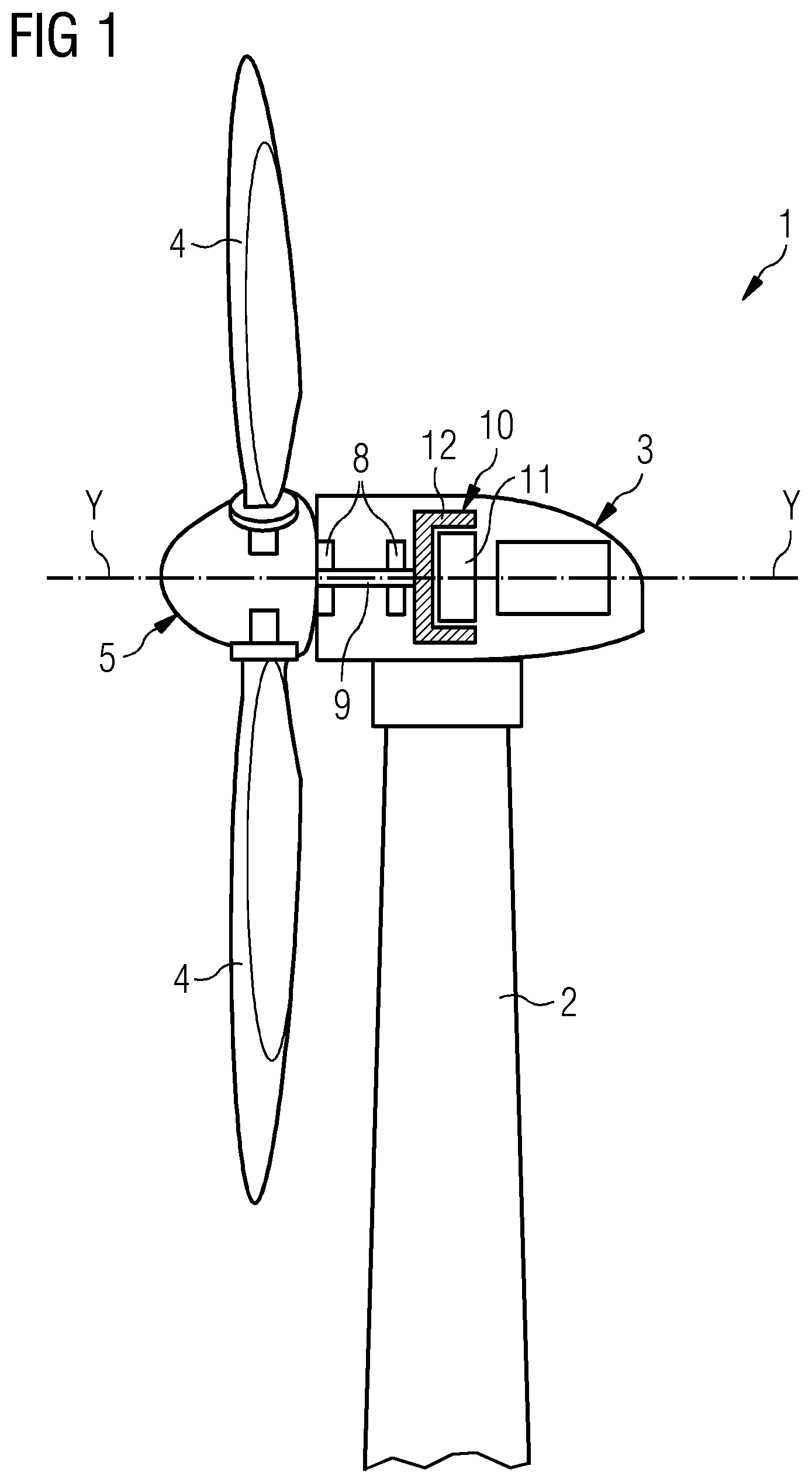
[0022] FIG. 1 shows a schematic section of a wind turbine including an electrical generator with a stator geometry according to embodiments of the present invention;
[0023] FIG. 2 shows a partial cross section of an electrical generator in accordance with embodiments of the present invention;
[0024] FIG. 3 shows a partial cross section of a first embodiment of the electrical generator of FIG. 2; and
[0025] FIG. 4 shows a partial cross section of a second embodiment of the electrical generator of FIG. 2.
DETAILED DESCRIPTION
[0026] The illustrations in the drawings are schematic. It is noted that in different figures, similar or identical elements are provided with the same reference signs.
[0027] FIG. 1 shows a wind turbine 1 according to embodiments of the invention. The wind turbine 1 comprises a tower 2, which is mounted on a non-depicted foundation. A nacelle 3 is arranged on top of the tower 2.
[0028] The wind turbine 1 further comprises a wind rotor 5 having two, three or more blades 4 (in the perspective of FIG. 1 only two blades 4 are visible). The wind rotor 5 is rotatable around a rotational axis Y. When not differently specified, the terms axial, radial and circumferential in the following are made with reference to the rotational axis Y.
[0029] The blades 4 extend radially with respect to the rotational axis Y.
[0030] The wind turbine 1 comprises a concentrated winding electrical generator 10.
[0031] The wind rotor 5 is rotationally coupled with the electrical generator 10 by means of a rotatable main shaft 9.
[0032] According to other possible embodiments of the present invention (not represented in the attached figures), the wind rotor 5 is rotationally coupled directly with the electrical generator 10 (direct-drive generator configuration).
[0033] A schematically depicted bearing assembly 8 is provided in order to hold in place the rotor 5. The rotatable main shaft 9 extends along the rotational axis Y. The permanent magnet electrical generator 10 includes a stator 11 and a rotor 12. The rotor 12 is radially external to the stator 11 and is rotatable with respect to the stator 11 about the rotational axis Y. According to other embodiments of the present invention (not shown) the rotor is radially internal to the stator 11.
[0034] According to other possible embodiments of the present invention (not represented in the attached figures), embodiments of the present invention can be applied to any electrical generator or motor which has concentrated winding topology, for example geared drive-trains or electrical machine of the synchronous or asynchronous types.
[0035] According to other possible embodiments of the present invention (not represented in the attached figures), embodiments of the present invention can be applied to any electrical generator or motor which has a double-layer coil distributed winding.
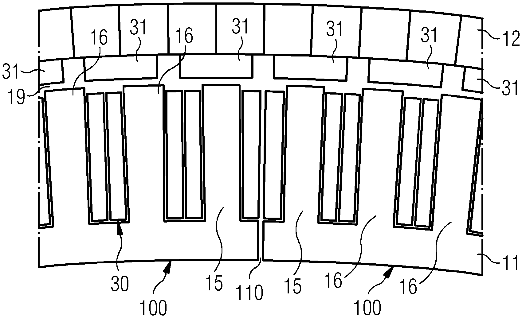
[0036] FIG. 2 shows a partial schematic view of a cross section, orthogonal to the rotational axis Y, of the electrical generator 10 with radially internal stator 11 and the radial external rotor 12. The electrical generator 10 includes a circumferential air gap 19, radially interposed between the stator 11 and the rotor 12. The rotor 12 includes a plurality of circumferentially distributed permanent magnets 31. The circumferential air gap 19 is radially interposed between the permanent magnets 31 and the stator 11.
[0037] The stator 11 includes a plurality of circumferential segments 100, which are circumferentially joined together in such a way that a circumferential gap 110 is interposed between two circumferentially adjacent stator segments 100. The stator 11 has a toothed structure, as described in the following, for housing a coil winding 30 arranged in each of the stator segments 100.
[0038] According to other possible embodiments of the present invention (not represented in the attached figures), embodiments of the present invention and the description which follows is applied to a rotor of an electrical machine.
[0039] With reference to FIGS. 3 and 4, each segment 100 includes a segment body 22 circumferentially extending about the longitudinal axis Y between two circumferential ends 23.
[0040] The segment body 22 includes a yoke 13, a plurality of teeth 15, 16 and a plurality of slots 17, 18.
[0041] Each tooth 15, 16 protrudes from the yoke 13 according to a radial direction orthogonal to the longitudinal axis Y. The plurality of teeth 15, 16 is circumferentially distributed between two end teeth 15 of the plurality of teeth 15, 16. Each end tooth 15 circumferentially extends between two respective side faces 25. The plurality of teeth 15, 16 comprises at least one intermediate tooth 16 (two intermediate teeth 16 are shown in FIGS. 3 and 4) circumferentially comprised between the end teeth 15. Each intermediate tooth 16 circumferentially extends between two respective side faces 26.
[0042] The plurality of slots 17, 18 are circumferentially interposed between the teeth 15, 16 and circumferentially distributed between two end slots 17. Each end slot 17 is circumferentially comprised between a respective end tooth 15 and a respective circumferential end 23 of the segment body 22. The plurality of slots 17, 18 comprise a plurality of intermediate slots 18 (two complete intermediate slot 18 are shown in FIGS. 3 and 4) circumferentially comprised between the two end slots 17.
[0043] The coil winding 30 is a double-layer winding including two side coils 41 respectively housed in the end slots 17 and two coils 42 in each of the intermediate slots 18. Each of the side coils 41 and of the coils 42 extends radially from the yoke towards the radial external end of the respective slot 17, 18, i.e. towards the circumferential air gap 19.
[0044] According to possible embodiments of the present invention, the coil winding 30 may by a coil concentrated winding or a double-layer coil distributed winding.
[0045] With reference to the embodiment of FIG. 3, the two side faces 25 of the two end teeth 15 are radially oriented with respect to each other and the two side faces 26 of each intermediate tooth 16 are parallel to each other.
[0046] According to other embodiments of the present invention, the two side faces 25 of the two end teeth 15 are inclined with respect to each other.
[0047] According to the embodiment of FIG. 3, the intermediate slots 18 have a lower copper fill factor because a V-shaped gap 28 is provided between the two coils 42 housed in each intermediate slot 18. This allows a reduction in the end winding length afforded by utilizing an easier coil insertion procedure, i.e. the coil does not have to be deformed to pass over the wider tooth top.
[0048] At the circumferentially end, instead a parallel slot design geometry is provided for the end slot 17, i.e. the side faces 25 of the end teeth 15 are parallel to the circumferential end 23 of the segment 100, thus offering an improved good slot fill factor, which is particularly advantageous for machines with large conductor sizes. The use of parallel slots further allows achieving a torque ripple reduction.
[0049] With reference to the embodiment of FIG. 4, the two side faces 25 of the two end teeth 15 are parallel to each other and the two side faces 26 of each intermediate tooth 16 are radially oriented with respect to each other.
[0050] According to other embodiments of the present invention, the two side faces 26 of each intermediate tooth 16 are inclined with respect to each other.
[0051] According to the embodiment of FIG. 4, the intermediate slots 18 exhibits a parallel slot design geometry, which is characterized by a higher copper fill factor than in the embodiment of FIG. 3, because a smaller and constant gap 28 is provided between the two coils 42 housed in each intermediate slot 18. This offers an improved good slot fill factor, which is particularly advantageous for machines with large conductor sizes. The use of a parallel slot geometry further allows achieving a torque ripple reduction.
[0052] At the circumferentially end, instead a parallel tooth design geometry is provided for the end teeth 15, thus reducing the copper fill factor, with a consequent reduction in end winding length afforded by utilizing an easier coil insertion procedure, i.e. the coil does not have to be deformed to pass over the wider tooth top, as it is the case in a parallel slot design geometry.
[0053] In both embodiments, a mixture of tooth designs combines the advantages of both designs in order to reduce the torque and power harmonics induced by the addition of a required segment tolerance gap.
[0054] Further, the dimension and shape of the gap can be efficiently controlled by efficiently combining the parallel slot design geometry with the parallel tooth design geometry, as described above.
[0055] Although the present invention has been disclosed in the form of preferred embodiments and variations thereon, it will be understood that numerous additional modifications and variations could be made thereto without departing from the scope of the intention.
[0056] For the sake of clarity, it is to be understood that the use of "a" or "an" throughout this application does not exclude a plurality, and "comprising" does not exclude other steps or elements. The mention of a "unit" or a "module" does not preclude the use of more than one unit or module.
* * * * *
D00000
D00001
D00002
D00003
XML
uspto.report is an independent third-party trademark research tool that is not affiliated, endorsed, or sponsored by the United States Patent and Trademark Office (USPTO) or any other governmental organization. The information provided by uspto.report is based on publicly available data at the time of writing and is intended for informational purposes only.
While we strive to provide accurate and up-to-date information, we do not guarantee the accuracy, completeness, reliability, or suitability of the information displayed on this site. The use of this site is at your own risk. Any reliance you place on such information is therefore strictly at your own risk.
All official trademark data, including owner information, should be verified by visiting the official USPTO website at www.uspto.gov. This site is not intended to replace professional legal advice and should not be used as a substitute for consulting with a legal professional who is knowledgeable about trademark law.