End-to-end Resource Visibility And Tracking System
Morgan; Rebecca Stepp ; et al.
U.S. patent application number 16/400870 was filed with the patent office on 2020-04-30 for end-to-end resource visibility and tracking system. This patent application is currently assigned to BANK OF AMERICA CORPORATION. The applicant listed for this patent is BANK OF AMERICA CORPORATION. Invention is credited to Shawn Cart Gunsolley, Robert Edward Marshall, Rebecca Stepp Morgan, Deirdre Spehar, Judith C. Taylor.
| Application Number | 20200134618 16/400870 |
| Document ID | / |
| Family ID | 70325522 |
| Filed Date | 2020-04-30 |


| United States Patent Application | 20200134618 |
| Kind Code | A1 |
| Morgan; Rebecca Stepp ; et al. | April 30, 2020 |
END-TO-END RESOURCE VISIBILITY AND TRACKING SYSTEM
Abstract
Embodiments of the invention are directed to a system, method, or computer program product for end-to-end resource visibility and tracking. In this way, an electronic tag is generated and distributed on a block chain network. The tag may identify a resource set and ultimately integrate with downstream systems for visualization of resource deposits and distributions within the bag. In this way, the invention provides a tool for a single source platform for tracking of status checks and digitized resource chain monitoring network. In this way, the invention creates a complete end-to-end digital fingerprint of physical resource tracking during a life cycle utilizing block chain technology with a distributed ledger to identify each touch point of the life cycle.
| Inventors: | Morgan; Rebecca Stepp; (Charlottesville, VA) ; Marshall; Robert Edward; (Charlotte, NC) ; Taylor; Judith C.; (Charlotte, NC) ; Gunsolley; Shawn Cart; (Charlotte, NC) ; Spehar; Deirdre; (Belleville, IL) | ||||||||||
| Applicant: |
|
||||||||||
|---|---|---|---|---|---|---|---|---|---|---|---|
| Assignee: | BANK OF AMERICA CORPORATION Charlotte NC |
||||||||||
| Family ID: | 70325522 | ||||||||||
| Appl. No.: | 16/400870 | ||||||||||
| Filed: | May 1, 2019 |
Related U.S. Patent Documents
| Application Number | Filing Date | Patent Number | ||
|---|---|---|---|---|
| 62751138 | Oct 26, 2018 | |||
| Current U.S. Class: | 1/1 |
| Current CPC Class: | H04L 9/3239 20130101; H04L 2209/38 20130101; G07F 19/211 20130101; H04L 9/0637 20130101; G06Q 20/38215 20130101; H04L 9/3236 20130101; G07F 19/206 20130101; G06Q 20/401 20130101; G06Q 20/3221 20130101; G06Q 40/04 20130101; H04L 2209/56 20130101; G06Q 20/42 20130101; G06Q 40/02 20130101 |
| International Class: | G06Q 20/38 20060101 G06Q020/38; G06Q 40/02 20060101 G06Q040/02; G06Q 20/32 20060101 G06Q020/32; G06Q 20/40 20060101 G06Q020/40; H04L 9/06 20060101 H04L009/06 |
Claims
1. A system for an end-to-end distributed network tag, the system comprising: a memory device with computer-readable program code stored thereon; a communication device; a processing device operatively coupled to the memory device and the communication device, wherein the processing device is configured to execute the computer-readable program code to: authorize a user for access to a platform tool for resource life cycle monitoring, wherein the platform tool displays data from a distributed network for touch point identification of the resource life cycle; identify deployment of a tag on a resource set, wherein the tag is a standardized scannable tag, wherein upon initial deployment the tag transmits resource information associated with the resource set to the distributed network; receive scanning confirmation from the tag, wherein the scanning occurs at one or more of the touch points across the resource life cycle; generate a block for the touch point based on the scanning confirmation, wherein the block is added to the distributed ledger for the resource life cycle monitoring and comprises updated resource information associated with the resource set; and complete resource life cycle monitoring upon final distribution of resources from the resource set.
2. The system of claim 1, wherein resource life cycle monitoring of the resource set comprising physical currency at each of the touch points for an end-to-end identification of a location of the physical currency and processing stage of the physical currency.
3. The system of claim 1, further comprising providing regulatory compliance satisfaction materials via the platform tool and transmit the regulator compliance satisfaction materials to the authorized user.
4. The system of claim 1, further comprising gathering of the resource life cycle monitoring of multiple tags for identification of processing delay or soft point trends in multiple resource sets end-to-end life cycle.
5. The system of claim 1, wherein the tag comprises sensors for transmission of data upon being scanned at a touch point along the resource life cycle.
6. The system of claim 1, wherein the resource set is a set of multiple physical currency from one or more owners within a bag.
7. The system of claim 1, wherein the distributed network is a private distributed block chain network for monitoring touch points across the resource set end-to-end of the resource life cycle.
8. The system of claim 1, wherein the standardized scannable tag is physically affixed to the resource set, wherein the resource set comprises physical currency.
9. A computer program product for an end-to-end distributed network tag, the computer program product comprising at least one non-transitory computer-readable medium having computer-readable program code portions embodied therein, the computer-readable program code portions comprising: an executable portion configured for authorizing a user for access to a platform tool for resource life cycle monitoring, wherein the platform tool displays data from a distributed network for touch point identification of the resource life cycle; an executable portion configured for identifying deployment of a tag on a resource set, wherein the tag is a standardized scannable tag, wherein upon initial deployment the tag transmits resource information associated with the resource set to the distributed network; an executable portion configured for receiving scanning confirmation from the tag, wherein the scanning occurs at one or more of the touch points across the resource life cycle; an executable portion configured for generating a block for the touch point based on the scanning confirmation, wherein the block is added to the distributed ledger for the resource life cycle monitoring and comprises updated resource information associated with the resource set; and an executable portion configured for completing resource life cycle monitoring upon final distribution of resources from the resource set.
10. The computer program product of claim 9, wherein resource life cycle monitoring of the resource set comprising physical currency at each of the touch points for an end-to-end identification of a location of the physical currency and processing stage of the physical currency.
11. The computer program product of claim 9, further comprising an executable portion configured for providing regulatory compliance satisfaction materials via the platform tool and transmit the regulator compliance satisfaction materials to the authorized user.
12. The computer program product of claim 9, further comprising an executable portion configured for gathering of the resource life cycle monitoring of multiple tags for identification of processing delay or soft point trends in multiple resource sets end-to-end life cycle.
13. The computer program product of claim 9, wherein the tag comprises sensors for transmission of data upon being scanned at a touch point along the resource life cycle and is physically affixed to the resource set.
14. The computer program product of claim 9, wherein the distributed network is a private distributed block chain network for monitoring touch points across the resource set end-to-end of the resource life cycle.
15. A computer-implemented method for an end-to-end distributed network tag, the method comprising: providing a computing system comprising a computer processing device and a non-transitory computer readable medium, where the computer readable medium comprises configured computer program instruction code, such that when said instruction code is operated by said computer processing device, said computer processing device performs the following operations: authorizing a user for access to a platform tool for resource life cycle monitoring, wherein the platform tool displays data from a distributed network for touch point identification of the resource life cycle; identifying deployment of a tag on a resource set, wherein the tag is a standardized scannable tag, wherein upon initial deployment the tag transmits resource information associated with the resource set to the distributed network; receiving scanning confirmation from the tag, wherein the scanning occurs at one or more of the touch points across the resource life cycle; generating a block for the touch point based on the scanning confirmation, wherein the block is added to the distributed ledger for the resource life cycle monitoring and comprises updated resource information associated with the resource set; and completing resource life cycle monitoring upon final distribution of resources from the resource set.
16. The computer-implemented method of claim 15, wherein resource life cycle monitoring of the resource set comprising physical currency at each of the touch points for an end-to-end identification of a location of the physical currency and processing stage of the physical currency.
17. The computer-implemented method of claim 15, further comprising providing regulatory compliance satisfaction materials via the platform tool and transmit the regulator compliance satisfaction materials to the authorized user.
18. The computer-implemented method of claim 15, further comprising gathering of the resource life cycle monitoring of multiple tags for identification of processing delay or soft point trends in multiple resource sets end-to-end life cycle.
19. The computer-implemented method of claim 15, wherein the tag comprises sensors for transmission of data upon being scanned at a touch point along the resource life cycle and is physically affixed to the resource set.
20. The computer-implemented method of claim 15, wherein the distributed network is a private distributed block chain network for monitoring touch points across the resource set end-to-end of the resource life cycle.
Description
CROSS-REFERENCE TO RELATED APPLICATIONS
[0001] This application claims the benefit of U.S. Provisional Patent Application Ser. No. 62/751,138, filed Oct. 26, 2018 entitled "System for Resource Visibility," the entirety of which is incorporated herein by reference.
BACKGROUND
[0002] Present conventional systems do not have the capability to allow a user to track resource distribution and deposits from conception through supply chain. Currently, manual sorting of resources is performed and portions of the resource supply chain are not visible. As such, there exists a need for a system to perform tagging and tracking of resource distribution and resource exchange through the supply chain.
BRIEF SUMMARY
[0003] The following presents a simplified summary of one or more embodiments of the invention in order to provide a basic understanding of such embodiments. This summary is not an extensive overview of all contemplated embodiments, and is intended to neither identify key or critical elements of all embodiments, nor delineate the scope of any or all embodiments. Its sole purpose is to present some concepts of one or more embodiments in a simplified form as a prelude to the more detailed description that is presented later.
[0004] Embodiments of the present invention address these and/or other needs by providing an innovative system, method and computer program product for resource visibility and entity resource exchange systems.
[0005] The resource visibility system comprise a standardized across entity system for the ability for user entities, such as commercial customers to create an electronic deposit ticket from a mobile application, generation of a tag associated with a bag and identifying the bag, and ultimately integrate with downstream systems for scanning of the tag for visualization of resource deposits and distributions from the user. In this way, the invention provides a tool for a single source for users to track deposits status and track performance of armored carriers and the like. In this way, the resource visibility system provides a digitized resource or cash supply chain monitoring network. As such, creating a complete end-to-end digital fingerprint of where physical currency is during its life cycle at the bag level. The system may utilize block chain technology with a distributed ledger to identify each location of the bag during the life cycle. This allows for regulatory compliance and tracking of the bags. The invention provides standards that apply supply chain logistics and tools that entities and financial institutions may utilize without paper manifests or deposit tickets. Instead, the invention creates a tag, such as a bar code, QR code, RFID tag, or the like that can be scanned and reconciled against an electronic shipping manifest within a block chain network associated with the cash within a bag. At the end of each day, the system may reconcile the distributed ledger.
[0006] Embodiments of the invention comprise a system, method, and computer program product for an end-to-end distributed network tag, the invention comprising: authorizing a user for access to a platform tool for resource life cycle monitoring, wherein the platform tool displays data from a distributed network for touch point identification of the resource life cycle; identifying deployment of a tag on a resource set, wherein the tag is a standardized scannable tag, wherein upon initial deployment the tag transmits resource information associated with the resource set to the distributed network; receiving scanning confirmation from the tag, wherein the scanning occurs at one or more of the touch points across the resource life cycle; generating a block for the touch point based on the scanning confirmation, wherein the block is added to the distributed ledger for the resource life cycle monitoring and comprises updated resource information associated with the resource set; and completing resource life cycle monitoring upon final distribution of resources from the resource set.
[0007] In some embodiments, resource life cycle monitoring of the resource set comprising physical currency at each of the touch points for an end-to-end identification of a location of the physical currency and processing stage of the physical currency.
[0008] In some embodiments, the invention further comprises providing regulatory compliance satisfaction materials via the platform tool and transmit the regulator compliance satisfaction materials to the authorized user.
[0009] In some embodiments, the invention further comprises gathering of the resource life cycle monitoring of multiple tags for identification of processing delay or soft point trends in multiple resource sets end-to-end life cycle.
[0010] In some embodiments, the tag comprises sensors for transmission of data upon being scanned at a touch point along the resource life cycle. In some embodiments, the resource set is a set of multiple physical currency from one or more owners within a bag. In some embodiments, the deployment of a tag on the resource set comprises physically adhering the tag to a bag associated with the resource set. In some embodiments, the standardized scannable tag is physically affixed to the resource set, wherein the resource set comprises physical currency.
[0011] In some embodiments, the distributed network is a private distributed block chain network for monitoring touch points across the resource set end-to-end of the resource life cycle.
[0012] The features, functions, and advantages that have been discussed may be achieved independently in various embodiments of the present invention or may be combined with yet other embodiments, further details of which can be seen with reference to the following description and drawings.
BRIEF DESCRIPTION OF THE DRAWINGS
[0013] Having thus described embodiments of the invention in general terms, reference will now be made to the accompanying drawings, wherein:
[0014] FIG. 1 provides an intelligent resource visibility and exchange system environment, in accordance with one embodiment of the present invention;
[0015] FIG. 2 provides an ATM system environment, in accordance with one embodiment of the present invention;
[0016] FIG. 3 provides a resource distribution or deposit location interface, in accordance with one embodiment of the present invention;
[0017] FIG. 4A provides centralized database architecture environment, in accordance with one embodiment of the present invention;
[0018] FIG. 4B provides a high level block chain system environment architecture, in accordance with one embodiment of the present invention;
[0019] FIG. 5 provides a high level process flow illustrating node interaction within a block chain system environment architecture, in accordance with one embodiment of the present invention;
[0020] FIG. 6 provides a detailed process flow illustrating resource visibility, in accordance with one embodiment of the present invention;
[0021] FIG. 7 provides a detailed process flow illustrating end-to-end resource tracking, in accordance with one embodiment of the present invention;
[0022] FIG. 8 provides a process map illustrating a lifecycle for resource visibility, in accordance with one embodiment of the present invention;
[0023] FIG. 9 provides a process map illustrating inputs for resource visibility, in accordance with one embodiment of the present invention; and
[0024] FIG. 10 provides a process map illustrating an entity resource exchange system, in accordance with one embodiment of the present invention.
DETAILED DESCRIPTION OF EMBODIMENTS OF THE INVENTION
[0025] Embodiments of the present invention will now be described more fully hereinafter with reference to the accompanying drawings, in which some, but not all, embodiments of the invention are shown. Indeed, the invention may be embodied in many different forms and should not be construed as limited to the embodiments set forth herein; rather, these embodiments are provided so that this disclosure will satisfy applicable legal requirements. Like numbers refer to elements throughout. Where possible, any terms expressed in the singular form herein are meant to also include the plural form and vice versa, unless explicitly stated otherwise. Also, as used herein, the term "a" and/or "an" shall mean "one or more," even though the phrase "one or more" is also used herein.
[0026] A "user" as used herein may refer to any customer of an entity or individual that interacts with an entity. In some embodiments, the user may be an entity. In some embodiments, identities of an individual may include online handles, usernames, aliases, family names, maiden names, nicknames, or the like. The user may interact with a financial institution as either a customer, supplier, entity or the like. Furthermore, as used herein the term "user device" or "mobile device" may refer to mobile phones, personal computing devices, tablet computers, wearable devices, and/or any portable electronic device capable of receiving and/or storing data therein.
[0027] As used herein, a "user interface" generally includes a plurality of interface devices and/or software that allow a customer to input commands and data to direct the processing device to execute instructions. For example, the user interface may include a graphical user interface (GUI) or an interface to input computer-executable instructions that direct the processing device to carry out specific functions. Input and output devices may include a display, mouse, keyboard, button, touchpad, touch screen, microphone, speaker, LED, light, joystick, switch, buzzer, bell, and/or other user input/output device for communicating with one or more users.
[0028] A "transaction" or "resource distribution" refers to any communication between a user and the financial institution or other entity to transfer funds for the purchasing or selling of a product. A transaction may refer to a purchase of goods or services, a return of goods or services, a payment transaction, a credit transaction, or other interaction involving a user's account. In the context of a financial institution, a transaction may refer to one or more of: a sale of goods and/or services, initiating an automated teller machine (ATM) or online banking session, an account balance inquiry, a rewards transfer, an account money transfer or withdrawal, opening a bank application on a user's computer or mobile device, a user accessing their e-wallet, or any other interaction involving the user and/or the user's device that is detectable by the financial institution. A transaction may include one or more of the following: renting, selling, and/or leasing goods and/or services (e.g., groceries, stamps, tickets, DVDs, vending machine items, and the like); making payments to creditors (e.g., paying monthly bills; paying federal, state, and/or local taxes; and the like); sending remittances; loading money onto stored value cards (SVCs) and/or prepaid cards; donating to charities; and/or the like.
[0029] In various embodiments, the point-of-transaction device (POT) may be or include a merchant machine and/or server and/or may be or include the mobile device of the user may function as a point of transaction device. The embodiments described herein may refer to the use of a transaction, transaction event or point of transaction event to trigger the steps, functions, routines etc. described herein. In various embodiments, occurrence of a transaction triggers the sending of information such as alerts and the like. As used herein, a "bank account" refers to a credit account, a debit/deposit account, or the like. Although the phrase "bank account" includes the term "bank," the account need not be maintained by a bank and may, instead, be maintained by other financial institutions. For example, in the context of a financial institution, a transaction may refer to one or more of a sale of goods and/or services, an account balance inquiry, a rewards transfer, an account money transfer, opening a bank application on a user's computer or mobile device, a user accessing their e-wallet or any other interaction involving the user and/or the user's device that is detectable by the financial institution. As further examples, a transaction may occur when an entity associated with the user is alerted via the transaction of the user's location. A transaction may occur when a user accesses a building, uses a rewards card, and/or performs an account balance query. A transaction may occur as a user's mobile device establishes a wireless connection, such as a Wi-Fi connection, with a point-of-sale terminal. In some embodiments, a transaction may include one or more of the following: purchasing, renting, selling, and/or leasing goods and/or services (e.g., groceries, stamps, tickets, DVDs, vending machine items, etc.); withdrawing cash; making payments to creditors (e.g., paying monthly bills; paying federal, state, and/or local taxes and/or bills; etc.); sending remittances; transferring balances from one account to another account; loading money onto stored value cards (SVCs) and/or prepaid cards; donating to charities; and/or the like.
[0030] In some embodiments, the transaction may refer to an event and/or action or group of actions facilitated or performed by a user's device, such as a user's mobile device. Such a device may be referred to herein as a "point-of-transaction device". A "point-of-transaction" could refer to any location, virtual location or otherwise proximate occurrence of a transaction. A "point-of-transaction device" may refer to any device used to perform a transaction, either from the user's perspective, the merchant's perspective or both. In some embodiments, the point-of-transaction device refers only to a user's device, in other embodiments it refers only to a merchant device, and in yet other embodiments, it refers to both a user device and a merchant device interacting to perform a transaction. For example, in one embodiment, the point-of-transaction device refers to the user's mobile device configured to communicate with a merchant's point of sale terminal, whereas in other embodiments, the point-of-transaction device refers to the merchant's point of sale terminal configured to communicate with a user's mobile device, and in yet other embodiments, the point-of-transaction device refers to both the user's mobile device and the merchant's point of sale terminal configured to communicate with each other to carry out a transaction.
[0031] In some embodiments, a point-of-transaction device is or includes an interactive computer terminal that is configured to initiate, perform, complete, and/or facilitate one or more transactions. A point-of-transaction device could be or include any device that a user may use to perform a transaction with an entity, such as, but not limited to, an ATM, a loyalty device such as a rewards card, loyalty card or other loyalty device, a magnetic-based payment device (e.g., a credit card, debit card, etc.), a personal identification number (PIN) payment device, a contactless payment device (e.g., a key fob), a radio frequency identification device (RFID) and the like, a computer, (e.g., a personal computer, tablet computer, desktop computer, server, laptop, etc.), a mobile device (e.g., a smartphone, cellular phone, personal digital assistant (PDA) device, MP3 device, personal GPS device, etc.), a merchant terminal, a self-service machine (e.g., vending machine, self-checkout machine, etc.), a public and/or business kiosk (e.g., an Internet kiosk, ticketing kiosk, bill pay kiosk, etc.), a gaming device, and/or various combinations of the foregoing.
[0032] In some embodiments, a point-of-transaction device is operated in a public place (e.g., on a street corner, at the doorstep of a private residence, in an open market, at a public rest stop, etc.). In other embodiments, the point-of-transaction device is additionally or alternatively operated in a place of business (e.g., in a retail store, post office, banking center, grocery store, factory floor, and the like). In accordance with some embodiments, the point-of-transaction device is not owned by the user of the point-of-transaction device. Rather, in some embodiments, the point-of-transaction device is owned by a mobile business operator or a point-of-transaction operator (e.g., merchant, vendor, salesperson, and the like). In yet other embodiments, the point-of-transaction device is owned by the financial institution offering the point-of-transaction device providing functionality in accordance with embodiments of the invention described herein.
[0033] Further, the term "payment credential" or "payment vehicle," as used herein, may refer to any of, but is not limited to refers to any of, but is not limited to, a physical, electronic (e.g., digital), or virtual transaction vehicle that can be used to transfer money, make a payment (for a service or good), withdraw money, redeem or use loyalty points, use or redeem coupons, gain access to physical or virtual resources, and similar or related transactions. For example, in some embodiments, the payment vehicle is a bank card issued by a bank which a customer may use to perform purchase transactions. However, in other embodiments, the payment vehicle is a virtual debit card housed in a mobile device of the customer, which can be used to electronically interact with an automated teller machine (ATM) or the like to perform financial transactions. Thus, it will be understood that the payment vehicle can be embodied as an apparatus (e.g., a physical card, a mobile device, or the like), or as a virtual transaction mechanism (e.g., a digital transaction device, digital wallet, a virtual display of a transaction device, or the like).
[0034] In some embodiments, information associated with the purchase transaction is received from a POT including a point-of-sale (POS) terminal during a transaction involving a consumer and a merchant. For example, a consumer checking out at a retail merchant, such as a grocer, may provide to the grocer the one or more goods or products that he is purchasing together with a payment method, loyalty card, and possibly personal information, such as the name of the consumer. This information along with information about the merchant may be aggregated or collected at the POS terminal and routed to the system or server of the present invention or otherwise a third party affiliate of an entity managing the system of this invention. In other embodiments when the purchase transaction occurs over the Internet, the information associated with the purchase transaction is collected at a server providing an interface for conducting the Internet transaction. In such an embodiment, the consumer enters product, payment, and possibly personal information, such as a shipping address, into the online interface, which is then collected by the server. The server may then aggregate the transaction information together with merchant information and route the transaction and merchant information to the system of the present invention. It will be further be understood that the information associated with the purchase transaction may be received from any channel such as an automated teller machine (ATM), Internet, peer-to-peer network, POS, and/or the like.
[0035] Embodiments of the present invention address these and/or other needs by providing an innovative system, method and computer program product for resource visibility and entity resource exchange systems, and the like.
[0036] The invention further comprises an industry partnership between financial institutions, merchants, armored carriers, and governmental agencies to digitize the cash supply chain. This invention includes a set of standards to apply the same supply chain logistics and tools that the retail, health care, food service and many other industries have used to drive package/product handling efficiencies and reduce overall costs and issues to the cash supply chain.
[0037] In some embodiments, the resource visibility provides a digitized resource or cash supply chain monitoring. The invention provides standards that apply supply chain logistics and tools that entities and financial institutions may utilize the cash supply chain without paper manifests or deposit tickets. Instead, the invention has a tag, such as a bar code, QR code, RFID tag, or the like that can be scanned and reconciled against an electronic shipping manifest associated with the cash.
[0038] The resource visibility further comprise the ability for user entities, such as commercial customers to create an electronic deposit ticket from a mobile application, scan and ID bag and ultimately integrate with downstream systems for visualization of the resource deposits and distributions from the user. In this way, the invention provides a tool for a single source for users to track deposits status.
[0039] "Block chain" as used herein refers to a decentralized electronic ledger of data records which are authenticated by a federated consensus protocol. Multiple computer systems within the block chain, referred to herein as "nodes" or "compute nodes," each comprise a copy of the entire ledger of records. Nodes may write a data "block" to the block chain, the block comprising data regarding a transaction. In some embodiments, only miner nodes may write transactions to the block chain. In other embodiments, all nodes have the ability to write to the block chain. In some embodiments, the block may further comprise a time stamp and a pointer to the previous block in the chain. In some embodiments, the block may further comprise metadata indicating the node that was the originator of the transaction. In this way, the entire record of transactions is not dependent on a single database which may serve as a single point of failure; the block chain will persist so long as the nodes on the block chain persist. A "private block chain" is a block chain in which only authorized nodes may access the block chain. In some embodiments, nodes must be authorized to write to the block chain. In some embodiments, nodes must also be authorized to read from the block chain. Once a transactional record is written to the block chain, it will be considered pending and awaiting authentication by the miner nodes in the block chain.
[0040] "Miner node" as used herein refers to a networked computer system that authenticates and verifies the integrity of pending transactions on the block chain. The miner node ensures that the sum of the outputs of the transaction within the block matches the sum of the inputs. In some embodiments, a pending transaction may require validation by a threshold number of miner nodes. Once the threshold number of miners has validated the transaction, the block becomes an authenticated part of the block chain. By using this method of validating transactions via a federated consensus mechanism, duplicate or erroneous transactions are prevented from becoming part of the accepted block chain, thus reducing the risk of data record tampering and increasing the security of the transactions within the system.
[0041] A "block" as used herein may refer to one or more records of a file with each record comprising data for transmission to a server. In some embodiments, the term record may be used interchangeably with the term block to refer to one or more transactions or data within a file being transmitted.
[0042] The resource visibility system comprise a standardized across entity system for the ability for user entities, such as commercial customers to create an electronic deposit ticket from a mobile application, generation of a tag associated with a bag and identifying the bag, and ultimately integrate with downstream systems for scanning of the tag for visualization of resource deposits and distributions from the user. In this way, the invention provides a tool for a single source for users to track deposits status and track performance of armored carriers and the like. In this way, the resource visibility system provides a digitized resource or cash supply chain monitoring network. As such, creating a complete end-to-end digital fingerprint of where physical currency is during its life cycle at the bag level. The system may utilize block chain technology with a distributed ledger to identify each location of the bag during the life cycle. This allows for regulatory compliance and tracking of the bags. The invention provides standards that apply supply chain logistics and tools that entities and financial institutions may utilize without paper manifests or deposit tickets. Instead, the invention creates a tag, such as a bar code, QR code, RFID tag, or the like that can be scanned and reconciled against an electronic shipping manifest within a block chain network associated with the cash within a bag. At the end of each day, the system may reconcile the distributed ledger.
[0043] FIG. 1 illustrates an intelligent resource visibility and exchange system environment 200, in accordance with one embodiment of the present invention. FIG. 1 provides the system environment 200 for which the distributive network system with specialized data feeds associated with error diagnosis document processing. FIG. 1 provides a unique system that includes specialized servers and system communicably linked across a distributive network of nodes required to perform the functions described herein.
[0044] As illustrated in FIG. 1, the entity server 208 is operatively coupled, via a network 201 to the user device 204, ATM 205, third party servers 207, block chain distributed network system 209, and to the resource visibility system 206. In this way, the entity server 208 can send information to and receive information from the user device 204, ATM 205, third party servers 207, block chain distributed network system 209, and the resource visibility system 206. FIG. 1 illustrates only one example of an embodiment of the system environment 200, and it will be appreciated that in other embodiments one or more of the systems, devices, or servers may be combined into a single system, device, or server, or be made up of multiple systems, devices, or servers.
[0045] The network 201 may be a system specific distributive network receiving and distributing specific network feeds and identifying specific network associated triggers. The network 201 may also be a global area network (GAN), such as the Internet, a wide area network (WAN), a local area network (LAN), or any other type of network or combination of networks. The network 201 may provide for wireline, wireless, or a combination wireline and wireless communication between devices on the network 201.
[0046] In some embodiments, the user 202 is an individual or entity that has one or more user devices 204 and is a customer of a financial institution exchanging or distributing resources. In some embodiments, the user 202 has a user device, such as a mobile phone, tablet, computer, or the like. FIG. 1 also illustrates a user device 204. The user device 204 may be, for example, a desktop personal computer, business computer, business system, business server, business network, a mobile system, such as a cellular phone, smart phone, personal data assistant (PDA), laptop, or the like. The user device 204 generally comprises a communication device 212, a processing device 214, and a memory device 216. The processing device 214 is operatively coupled to the communication device 212 and the memory device 216. The processing device 214 uses the communication device 212 to communicate with the network 201 and other devices on the network 201, such as, but not limited to the resource visibility system 206, the entity server 208, and the third party sever 207. As such, the communication device 212 generally comprises a modem, server, or other device for communicating with other devices on the network 201.
[0047] The user device 204 comprises computer-readable instructions 220 and data storage 218 stored in the memory device 216, which in one embodiment includes the computer-readable instructions 220 of a user application 222. In some embodiments, the user application 222 allows a user 202 to send and receive communications with the resource visibility system 206.
[0048] As further illustrated in FIG. 1, the resource visibility system 206 generally comprises a communication device 246, a processing device 248, and a memory device 250. As used herein, the term "processing device" generally includes circuitry used for implementing the communication and/or logic functions of the particular system. For example, a processing device may include a digital signal processor device, a microprocessor device, and various analog-to-digital converters, digital-to-analog converters, and other support circuits and/or combinations of the foregoing. Control and signal processing functions of the system are allocated between these processing devices according to their respective capabilities. The processing device may include functionality to operate one or more software programs based on computer-readable instructions thereof, which may be stored in a memory device.
[0049] The processing device 248 is operatively coupled to the communication device 246 and the memory device 250. The processing device 248 uses the communication device 246 to communicate with the network 201 and other devices on the network 201, such as, but not limited to the entity server 208, the third party server 207, the ATM 205, and the user device 204. As such, the communication device 246 generally comprises a modem, server, or other device for communicating with other devices on the network 201.
[0050] As further illustrated in FIG. 1, the resource visibility system 206 comprises computer-readable instructions 254 stored in the memory device 250, which in one embodiment includes the computer-readable instructions 254 of an application 258. In some embodiments, the memory device 250 includes data storage 252 for storing data related to the system environment 200, but not limited to data created and/or used by the application 258.
[0051] In one embodiment of the resource visibility system 206 the memory device 250 stores an application 258. In one embodiment of the invention, the application 258 may associate with applications having computer-executable program code. Furthermore, the resource visibility system 206, using the processing device 248 codes certain communication functions described herein. In one embodiment, the computer-executable program code of an application associated with the application 258 may also instruct the processing device 248 to perform certain logic, data processing, and data storing functions of the application. The processing device 248 is configured to use the communication device 246 to communicate with and ascertain data from one or more entity server 208, third party servers 207, ATM 205, block chain distributed network system 209, and/or user device 204.
[0052] As illustrated in FIG. 1, the third party server 207 is connected to the entity server 208, user device 204, ATM 205, block chain distributed network system 209, and resource visibility system 206. The third party server 207 has the same or similar components as described above with respect to the user device 204 and the resource visibility system 206. While only one third party server 207 is illustrated in FIG. 1, it is understood that multiple third party servers 207 may make up the system environment 200. The third party server 207 may be associated with one or more financial institutions, entities, or the like.
[0053] As illustrated in FIG. 1, the ATM 205 is connected to the entity server 208, user device 204, third party server 207, block chain distributed network system 209, and resource visibility system 206. The ATM 205 has the same or similar components as described above with respect to the user device 204 and the resource visibility system 206. While only one ATM 205 is illustrated in FIG. 1, it is understood that multiple ATM 205 may make up the system environment 200.
[0054] As illustrated in FIG. 1, the entity server 208 is connected to the third party server 207, user device 204, ATM 205, block chain distributed network system 209, and resource visibility system 206. The entity server 208 may be associated with the resource visibility system 206. The entity server 208 has the same or similar components as described above with respect to the user device 204 and the resource visibility system 206. While only one entity server 208 is illustrated in FIG. 1, it is understood that multiple entity server 208 may make up the system environment 200. It is understood that the servers, systems, and devices described herein illustrate one embodiment of the invention. It is further understood that one or more of the servers, systems, and devices can be combined in other embodiments and still function in the same or similar way as the embodiments described herein. The entity server 208 may generally include a processing device communicably coupled to devices as a memory device, output devices, input devices, a network interface, a power source, one or more chips, and the like. The entity server 208 may also include a memory device operatively coupled to the processing device. As used herein, memory may include any computer readable medium configured to store data, code, or other information. The memory device may include volatile memory, such as volatile Random Access Memory (RAM) including a cache area for the temporary storage of data. The memory device may also include non-volatile memory, which can be embedded and/or may be removable. The non-volatile memory may additionally or alternatively include an electrically erasable programmable read-only memory (EEPROM), flash memory or the like.
[0055] The memory device may store any of a number of applications or programs which comprise computer-executable instructions/code executed by the processing device to implement the functions of the entity server 208 described herein.
[0056] As further illustrated in FIG. 1, the block chain distributed network system 209 comprises computer-readable instructions stored in the memory device, which in one embodiment includes the computer-readable instructions of a resource application. In some embodiments, the memory device includes data storage for storing data related to the system environment.
[0057] Embodiments of the block chain distributed network system 209 may include multiple systems, servers, computers or the like maintained by one or many entities. FIG. 1 merely illustrates one of those systems that, typically, interacts with many other similar systems to form the block chain. The block chain distributed network system 209 will be outlined below in more detail with respect to FIGS. 4-5. In some embodiments, the resource visibility system 206206 may be part of the block chain. Similarly, in some embodiments, the block chain distributed network system 209 is part of the resource visibility system 206. In other embodiments, the resource visibility system 206 is distinct from the block chain distributed network system 209.
[0058] In one embodiment of the block chain distributed network system 209 the memory device stores, but is not limited to, a resource application and a distributed ledger. In some embodiments, the distributed ledger stores data including, but not limited to, the block chains for resource requesting, generating, and completing.
[0059] In one embodiment of the invention, both the resource application and the distributed ledger may associate with applications having computer-executable program code that instructs the processing device to operate the network communication device to perform certain communication functions involving described herein. In one embodiment, the computer-executable program code of an application associated with the distributed ledger and resource application may also instruct the processing device to perform certain logic, data processing, and data storing functions of the application.
[0060] The processing device is configured to use the communication device to gather data, such as data corresponding to transactions, blocks or other updates to the distributed ledger from various data sources such as other block chain network system. The processing device stores the data that it receives in its copy of the distributed ledger stored in the memory device.
[0061] Using the intelligent resource visibility and exchange system environment 200 illustrated in FIG. 1, the invention comprises performing resource visibility and entity resource exchange. In some embodiments, the invention may utilize a resource distribution or deposit location. The resource distribution or deposit locations may include a financial institution, entity, ATM or the like. FIGS. 2 and 3 depict a resource distribution or deposit location. While FIGS. 2 and 3 illustrate an ATM, one of ordinary skill in the art will appreciate that one or more of the devices or systems illustrated are necessary devices for any resource distribution or deposit locations.
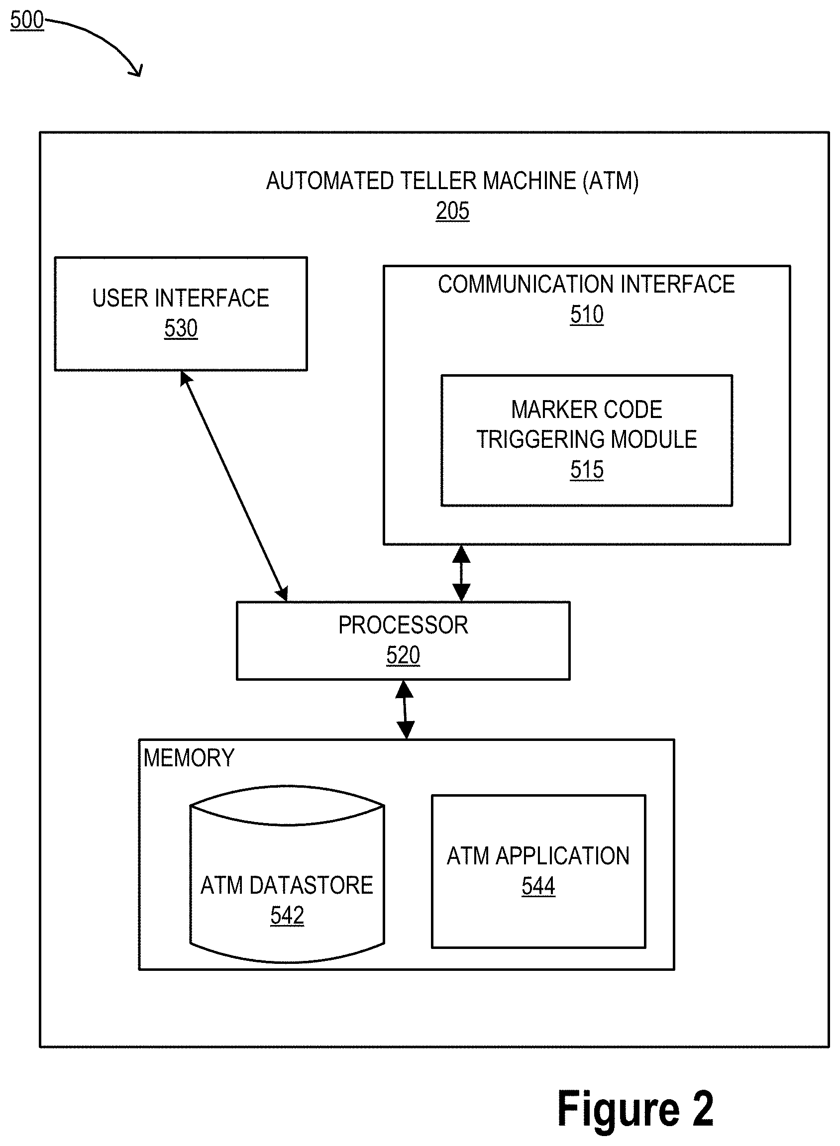
[0062] FIG. 2 illustrates an ATM system environment 500, in accordance with embodiments of the present invention. As illustrated in FIG. 2, the ATM 205 includes a communication interface 510, a processor 520, a user interface 530, and a memory 540 having an ATM datastore 542 and an ATM application 544 stored therein. As shown, the processor 520 is operatively connected to the communication interface 510, the user interface 530, and the memory 540.
[0063] The communication interface 510 of the ATM may include a marker code triggering module 515. The marker code triggering module 515 is configured to authorize a user via contact, contactless, and/or wireless information communication regarding the pin code or marker code inputted by the user. The marker code triggering module 515 may include a transmitter, receiver, smart card, key card, proximity card, radio frequency identification (RFID) tag and/or reader, and/or the like. In some embodiments, the marker code triggering module 515 communicates information via radio, IR, and/or optical transmissions. Generally, the marker code triggering module 515 is configured to operate as a transmitter and/or as a receiver. The marker code triggering module 515 functions to enable transactions with users using the ATM via identification of the user via physical authentication, contactless authorization, or the like. Also, it will be understood that the marker code triggering module 515 may be embedded, built, carried, and/or otherwise supported in and/or on the ATM 205. In some embodiments, the marker code triggering module 515 is not supported in and/or on the ATM 205, but the marker code triggering module 515 is otherwise operatively connected to the ATM 205 (e.g., where the marker code triggering module 515 is a peripheral device plugged into the ATM 205 or the like).
[0064] The communication interface 510 may generally also include a modem, server, transceiver, and/or other device for communicating with other devices and systems on a network.
[0065] The user interface 530 of the ATM 205 may include a display (e.g., a liquid crystal display, a touchscreen display, and/or the like) which is operatively coupled to the processor 520. The user interface 530 may include any number of other devices allowing the ATM 205 to transmit/receive data to/from a user, such as a keypad, keyboard, touch-screen, touchpad, microphone, mouse, joystick, other pointer device, button, soft key, and/or other input device(s).
[0066] As further illustrated in FIG. 2, the memory 540 may include ATM applications 544. It will be understood that the ATM applications 544 can be executable to initiate, perform, complete, and/or facilitate one or more portions of any embodiment described and/or contemplated herein. Generally, the ATM application 544 is executable to receive transaction instructions from the user and perform typical ATM functions, as appreciated by those skilled in the art. In some embodiments of the invention, the ATM application is configured to access content, such as data stored in memory, for example in the ATM datastore 542, or a database in communication with the ATM 205 and may transfer the content to the external apparatus if the external apparatus is configured for ATM communication.
[0067] Of course, the ATM 205 may require users to identify and/or authenticate themselves to the ATM 205 before the ATM 205 will initiate, perform, complete, and/or facilitate a transaction. For example, in some embodiments, the ATM 205 is configured (and/or the ATM application 544 is executable) to authenticate an ATM user based at least partially on an ATM debit card, smart card, token (e.g., USB token, or the like), username, password, pin, biometric information, and/or one or more other credentials that the user presents to the ATM 205. Additionally or alternatively, in some embodiments, the ATM 205 is configured to authenticate a user by using one-, two-, or multi-factor authentication. For example, in some embodiments, the ATM 205 requires two-factor authentication, such that the user must provide a valid debit card and enter the correct pin associated with the debit card in order to authenticate the user to the ATM 205. However, in some embodiments, the user may access the ATM 205 and view or receive content that may be transferred to/from the ATM 205.
[0068] FIG. 3 is an interface illustrating an ATM 600, in accordance with embodiments of the present invention. While an ATM is presented in FIG. 3, the device may be any resource distribution or deposit location such as an ATM, transaction device, kiosk, terminal, merchant location, online interface, financial institution interface, or the like. FIG. 3 provides a representative illustration of an ATM, in accordance with one embodiment of the present invention. In some embodiments, the representative ATM may comprise features similar to features found on a standard ATM. The lighting means 608 may be located above the display 602 that may provide a customer light for use during an ATM transaction. Of note, the display 602 may be vertically adjusted or horizontally adjusted along tracks or the like to position itself across the entire ATM. While currently illustrated in the upper left corner of the ATM, one will appreciate that the display may move to the right upper corner or below to the lower corners of the ATM and/or anywhere in between if necessary. The lighting means 608 may also be moved with the ATM display 602 and provide the customer a safety mechanism to aid in the ATM transaction.
[0069] The cash receptacle 606 may provide the customer means for receiving cash that the customer requests for withdraw through the ATM transaction. In some embodiments, the ATM may also include a contactless identification sensor 612, a contact identification sensor 614 such as a debit or ATM card acceptor, a keypad 604, a receipt receptacle 610, and a deposit receptacle 616. In some embodiments, the contactless identifier 612 and/or the contact identifier 614 may provide the ATM means of receiving identification from the customer. The customer may provide contactless or contact identification means through the ATM. The identification means using a contactless or contact identifications may be provided through several mechanisms, including, but not limited to, biometric identification, laser identification, magnetic strip identification, barcode identification, radio frequency (RF), a character recognition device, a magnetic ink, code readers, wireless communication, debit card scanning, ATM card scanning, and/or the like. The authentication from the contactless identifier of contact identifier may be read by the ATM application. After the authentication has been read, the system may provide the authentication to the financial institution to authorize an ATM transaction.
[0070] In some embodiments, the keypad 604 may provide for identification of the customer for use of the ATM. The keypad 604 may provide the customer means for inputting a pin number identification. In this way, the keypad 604 enables the customer to input his pin number into the ATM. In some embodiments, the pin number inputted on the keypad 604 may be read by the system. After the pin number has been read, the ATM may receive the pin number and provide authentication of the identification with the financial institution system.
[0071] The display 602 provides a means for displaying information related to the customer's ATM transaction. Display information may be, but is not limited to display of interfaces, such as the start-up interface and an ATM transaction interface. In some embodiments, the display 602 is a touch screen display module.
[0072] It is understood that the servers, systems, and devices described herein illustrate one embodiment of the invention. It is further understood that one or more of the servers, systems, and devices can be combined in other embodiments and still function in the same or similar way as the embodiments described herein.
[0073] The system integrates functionality of computer terminals onto user mobile devices for self-generation of denomination resources. Specifically, the system may self-generate digital resources for distribution and utilization as currency by the recipient in the form of a token. The user may, utilizing his/her resource distribution account, digitally extract resources to be digitally stored or transmitted to a receiving party for redemption at a later time. The digital resource will be treated as a physical resource and are provided based on removing the resource amount from the user's resource account, and the resource amount of the digital resources are held as pending. The system allows for these digital resources to be legal tender and anonymous as to the account and the user distributing the digital resources.
[0074] Furthermore, in some embodiments, the system may be integrated into an ATM. As such, the ATM may be able to self-generate digital resources with any denomination that the user requests withdraw from his/her resource account. The ATM may transmit the digital resources wirelessly, via near field communication (NFC), or the like to a user mobile device, third party mobile device, or the like. As such, the user may be able to select an odd denomination from the ATM and the ATM may generate the amount of the request via the digital resource distribution.
[0075] In some embodiments, the resource visibility provides a digitized resource or cash supply chain monitoring. The invention provides standards that apply supply chain logistics and tools that entities and financial institutions may utilize the cash supply chain without paper manifests or deposit tickets. Instead, the invention has a tag, such as a bar code, QR code, RFID tag, or the like that can be scanned and reconciled against an electronic shipping manifest associated with the cash.
[0076] The resource visibility further comprise the ability for user entities, such as commercial customers to create an electronic deposit ticket from a mobile application, scan and ID bag and ultimately integrate with downstream systems for visualization of the resource deposits and distributions from the user. In this way, the invention provides a tool for a single source for users to track deposits status.
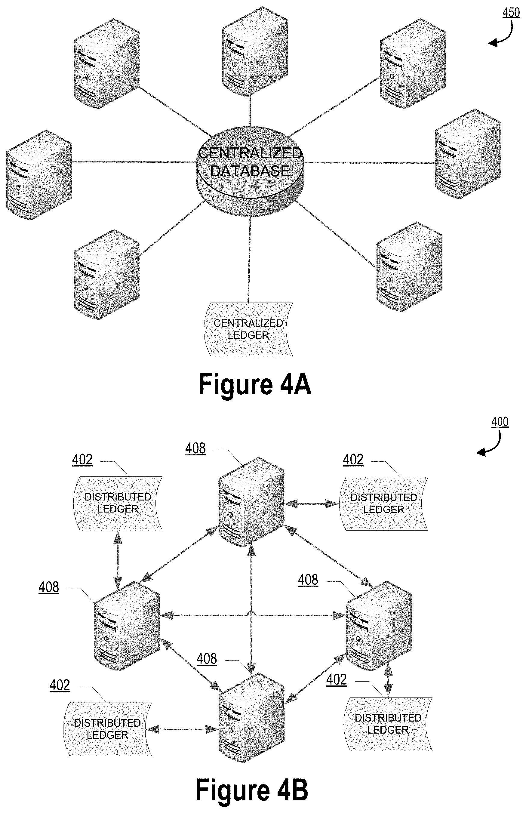
[0077] FIG. 4A illustrates a centralized database architecture environment 450, in accordance with one embodiment of the present invention. The centralized database architecture comprises multiple nodes from one or more sources and converge into a centralized database. The system, in this embodiment, may generate a single centralized ledger for data received from the various nodes. The single centralized ledger for data provides a difficult avenue for allowing access and reviewing a block of a data as it moves through the various applications.
[0078] FIG. 4B provides a general block chain system environment architecture 400, in accordance with one embodiment of the present invention. Rather than utilizing a centralized database of data for instrument conversion, as discussed above in FIG. 4A, various embodiments of the invention may use a decentralized block chain configuration or architecture as shown in FIG. 4B in order to facilitate the validation or failure location identification for file transmission. Such a decentralized block chain configuration ensures accurate mapping and tagging of blocks within a files during or after the transmission. Accordingly, a block chain configuration may be used to maintain an accurate ledger of files and the processing of transmission of the files by generation of building of one or more blocks for each file of the transmission. In this way, building a traceable and trackable historic view of each file transmission for failure location identification.
[0079] A block chain is a distributed database that maintains a list of data blocks, such as real-time resource availability associated with one or more accounts or the like, the security of which is enhanced by the distributed nature of the block chain. A block chain typically includes several nodes, which may be one or more systems, machines, computers, databases, data stores or the like operably connected with one another. In some cases, each of the nodes or multiple nodes are maintained by different entities. A block chain typically works without a central repository or single administrator. One well-known application of a block chain is the public ledger of transactions for cryptocurrencies. The data blocks recorded in the block chain are enforced cryptographically and stored on the nodes of the block chain.
[0080] A block chain provides numerous advantages over traditional databases. A large number of nodes of a block chain may reach a consensus regarding the validity of a transaction contained on the transaction ledger. As such, the status of the instrument and the resources associated therewith can be validated and cleared by one participant.
[0081] The block chain system typically has two primary types of records. The first type is the transaction type, which consists of the actual data stored in the block chain. The second type is the block type, which are records that confirm when and in what sequence certain transactions became recorded as part of the block chain. Transactions are created by participants using the block chain in its normal course of business, for example, when someone sends cryptocurrency to another person, and blocks are created by users known as "miners" who use specialized software/equipment to create blocks. In some embodiments, the block chain system is closed, as such the number of miners in the current system are known and the system comprises primary sponsors that generate and create the new blocks of the system. As such, any block may be worked on by a primary sponsor. Users of the block chain create transactions that are passed around to various nodes of the block chain. A "valid" transaction is one that can be validated based on a set of rules that are defined by the particular system implementing the block chain. For example, in the case of cryptocurrencies, a valid transaction is one that is digitally signed, spent from a valid digital wallet and, in some cases that meets other criteria.
[0082] As mentioned above and referring to FIG. 4B, a block chain system 400 is typically decentralized--meaning that a distributed ledger 402 (i.e., a decentralized ledger) is maintained on multiple nodes 408 of the block chain 400. One node in the block chain may have a complete or partial copy of the entire ledger or set of transactions and/or blocks on the block chain. Transactions are initiated at a node of a block chain and communicated to the various nodes of the block chain. Any of the nodes can validate a transaction, add the transaction to its copy of the block chain, and/or broadcast the transaction, its validation (in the form of a block) and/or other data to other nodes. This other data may include time-stamping, such as is used in cryptocurrency block chains. In some embodiments, the nodes 408 of the system might be financial institutions that function as gateways for other financial institutions. For example, a credit union might hold the account, but access the distributed system through a sponsor node.
[0083] Various other specific-purpose implementations of block chains have been developed. These include distributed domain name management, decentralized crowd-funding, synchronous/asynchronous communication, decentralized real-time ride sharing and even a general purpose deployment of decentralized applications.
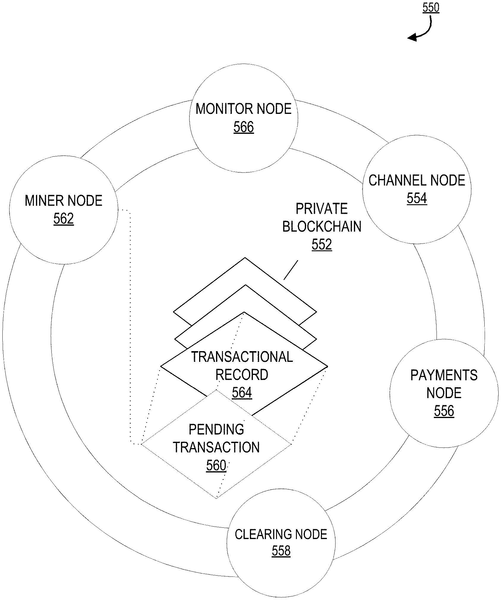
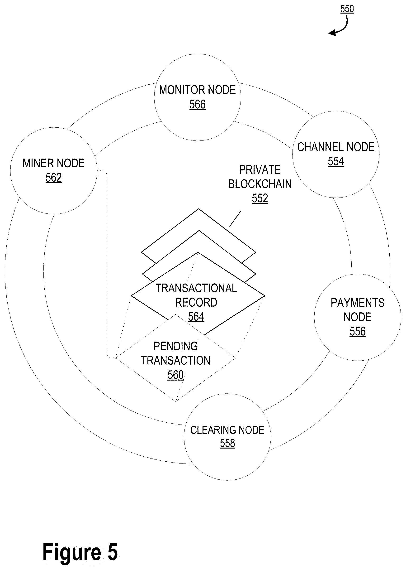
[0084] FIG. 5 provides a high level process flow illustrating node interaction within a block chain system environment architecture 550, in accordance with one embodiment of the present invention. As illustrated and discussed above, the block chain system may comprise at least one or more nodes used to generate blocks within file transmission for transmission validation or failure location identification during file transfers across servers.
[0085] In some embodiments, the channel node 554, payments node 556, monitor node 566 or the clearing node 558 may publish a pending transaction 560 to the private block chain 552. A pending transaction 560 as used herein may refer to a file being transferred with tag to the end of the file. At this stage, the transaction has not yet been validated by the miner node(s) 562, and the other nodes will delay executing their designated processes. The miner node 562 may be configured to detect a pending transaction 510 or steps in the process of transmitting the file. Upon verifying the integrity of the data in the pending transaction 560, the miner node 562 validates the transaction and adds the data as a transactional record 564, which is referred to as a block in some embodiments of the application, to the private block chain 552. Once a transaction has been authenticated in this manner, the nodes will consider the transactional record 564 to be valid and thereafter execute their designated processes accordingly. The transactional record 564 will provide information about what file was just processed and transmitted through and metadata coded therein for searchability of the transactional record 564 within a distributed ledger.
[0086] In some embodiments, the system may comprise at least one additional miner node 562. The system may require that pending transactions 560 be validated by a plurality of miner nodes 562 before becoming authenticated blocks on the block chain. In some embodiments, the systems may impose a minimum threshold number of miner nodes 562 needed to verify each file. The minimum threshold may be selected to strike a balance between the need for data integrity/accuracy versus expediency of processing. In this way, the efficiency of the computer system resources may be maximized.
[0087] Furthermore, in some embodiments, a plurality of computer systems are in operative networked communication with one another through a network. The network may be a system specific distributive network receiving and distributing specific network feeds and identifying specific network associated triggers. The network may also be a global area network (GAN), such as the Internet, a wide area network (WAN), a local area network (LAN), or any other type of network or combination of networks. The network may provide for wireline, wireless, or a combination wireline and wireless communication between devices on the network.
[0088] In some embodiments, the computer systems represent the nodes of the private block chain, such as the miner node or the like. In such an embodiment, each of the computer systems comprise the private block chain, providing for decentralized access to the block chain as well as the ability to use a consensus mechanism to verify the integrity of the data therein. In some embodiments, an upstream system and a downstream system are further operatively connected to the computer systems and each other through the network. The upstream system further comprises a private ledger and the private block chain. The downstream system further comprises the private block chain and an internal ledger, which in turn comprises a copy of the private ledger.
[0089] In some embodiments, a copy of private block chain may be stored on a durable storage medium within the computer systems or the upstream system or the downstream system. In some embodiments, the durable storage medium may be RAM. In some embodiments, the durable storage medium may be a hard drive or flash drive within the system.
[0090] The invention comprise a standardized across entity system for the ability for user entities, such as commercial customers to create an electronic deposit ticket from a mobile application, generation of a tag associated with a bag and identifying the bag, and ultimately integrate with downstream systems for scanning of the tag for visualization of resource deposits and distributions from the user. In this way, the invention provides a tool for a single source for users to track deposits status and track performance of armored carriers and the like. In this way, the resource visibility system provides a digitized resource or cash supply chain monitoring network. As such, creating a complete end-to-end digital fingerprint of where physical currency is during its life cycle at the bag level. The system may utilize block chain technology with a distributed ledger to identify each location of the bag during the life cycle. This allows for regulatory compliance and tracking of the bags. The invention provides standards that apply supply chain logistics and tools that entities and financial institutions may utilize without paper manifests or deposit tickets. Instead, the invention creates a tag, such as a bar code, QR code, RFID tag, or the like that can be scanned and reconciled against an electronic shipping manifest within a block chain network associated with the cash within a bag. At the end of each day, the system may reconcile the distributed ledger.
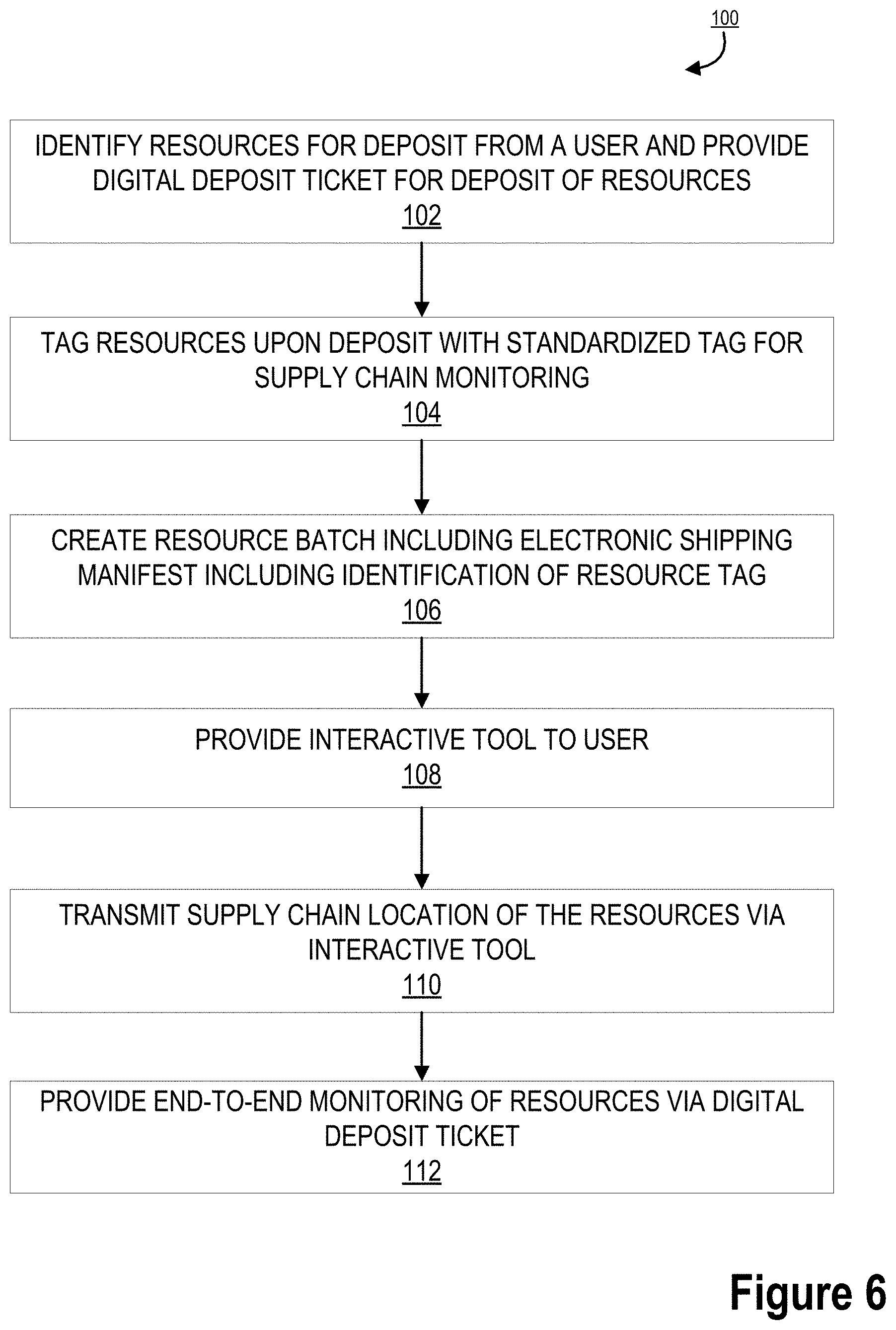
[0091] FIG. 6 provides a detailed process flow illustrating resource visibility 100, in accordance with one embodiment of the present invention. As illustrated in block 102, the process 100 is initiated by identifying resources for deposit from a user and providing a digital deposit ticket to the user for deposit of the resources. In this way, the user may be a commercial entity providing a deposit to a financial institution. The deposit may be a deposit of one or more resources from the user.
[0092] Next, as illustrated in block 104, the process 100 continues by tagging resources upon deposit with standardized tagging for supply chain monitoring. In this way, the system may tag a resource deposit. The tag may be any type of tag such as a barcode, RFID, QR code, or the like providing a unique identifier of the resources. In some embodiments, the tag may be a uniform communication language for resources across entities. Furthermore, the deposit may generate a block on the block chain for tracking of the blocks of the deposit via a distributed ledger based on blocks being added at each location along the end-to-end processing of the deposit.
[0093] As illustrated in block 106, the process 100 continues by creating a resource batch, such as a bag of cash from an ATM, or the like, that includes an electronic shipping manifest for the batch and includes an identification of each individual resource tag associated with each of the one or more resources within the batch that has a tag associated therewith.
[0094] The system may provide an interactive tool to a user for access to and visualization of the resources and supply chain associated with the resources for tracking each step of the resource along the supply chain, as illustrated in block 108. In this way, the supply chain location of the resources may be transmitted to the user, financial institution, regulatory institution, or the like via the interactive tool provided for the monitoring of the resource distribution, as illustrated in block 110. Finally, as illustrated in block 112, the process 100 is completed by providing an end-to-end monitoring of the resources via a digital deposit ticket provided to the user.
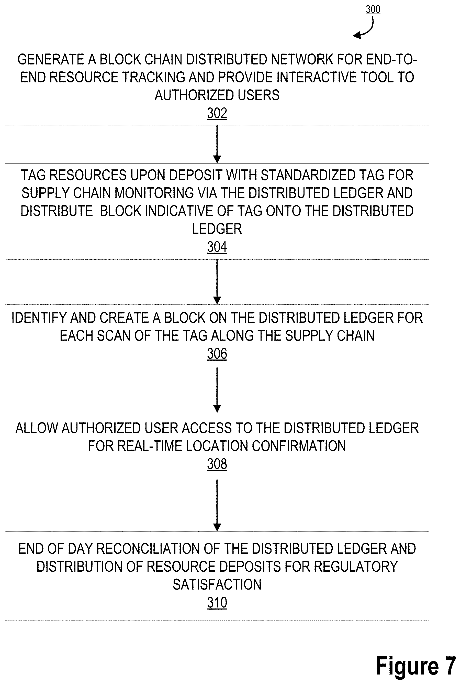
[0095] FIG. 7 provides a detailed process flow illustrating end-to-end resource tracking 300, in accordance with one embodiment of the present invention. As illustrated in block 302, the process 300 is initiated by generating a block chain distributed network for end-to-end resource tracking and providing an interactive tool associated with the distributed network to authorized users. In this way, the invention sets up a private block chain for monitoring the end-to-end transmission of physical cash as it moves from a location through armored vehicles to a vault, or the like and monitors the physical cash at each touch-point for end-to-end identification of the location of the physical cash and processing stage.
[0096] Next, as illustrated in block 304, the process 300 continues by tagging resources upon deposition with standardized tags for supply chain monitoring via the distributed ledger and initiation of a block being added to the distributed ledger associated with the tag. In this way, once physical cash is placed in a bag for transportation, a tag may be placed on the bag. The tag may be a standardized coded tag for scanning and identification of a location and contents of the bag. As such, upon scanning, the system recognizes the new tag and transmits the information about the bag, such as an amount, location, destination, and the like, to the block chain.
[0097] As illustrated in block 306, the process 300 continues by identifying and creating a block on the distributed ledger for each scan of the tag on the physical cash bag along the supply chain. In this way, at each location along the supply chain, the back may be scanned. Each time the bag is scanned, the system identifies the tag associated with the bag, identifies the scanner, identifies the time, identifies the location on the supply chain, and posts this information to the block chain for authorized user visualization. As illustrated in block 308, the system allows for authorized user access to the distributed ledger for real-time location confirmation and end of day reconciliation.
[0098] Finally, as illustrated in block 310, the process 300 is completed by allowing for end of day reconciliation of the distributed ledger and distribution of resource deposits for regulatory satisfaction.
[0099] Using this system, the invention is able to monitor the physical cash at each touch-point for end-to-end identification of the location of the physical cash and processing stage. As such, the invention provides for regulatory compliance satisfaction, physical cash settlement and reconciliation, and for identification of locations across a lifecycle associated with processing delays or soft points.
[0100] FIG. 8 provides a process map illustrating a lifecycle for resource visibility 700, in accordance with one embodiment of the present invention. As illustrated the financial institutions may include entity provided resource distribution or deposit locations such as a financial center or an ATM. Furthermore, the commercial entities, such as the commercial customer may provide treasury clients. The resources may be distributed to a carrier, such as an armored carrier or the like and transmitted to the vault. The resources may further be transferred to the federal reserve network. In this way, the resource visibility comprise the ability for user entities, such as commercial customers to create an electronic deposit ticket from a mobile application, scan and ID bag and ultimately integrate with downstream systems for visualization of the resource deposits and distributions from the user. In this way, the invention provides a tool for a single source for users to track deposits status.
[0101] FIG. 9 provides a process map illustrating inputs for resource visibility 800, in accordance with one embodiment of the present invention. As illustrated in block 801, the process 800 is initiated by creating a store deposit. The process 800 then continues by tracking the transportation of the resources, as illustrated in block 802. Next, as illustrated in block 803, the system may track the resources in the vault and finally, verify the posting of the resource distribution as illustrated in block 804. All of the steps of the process 800 are transmitted to a centralized data service including a web portal, mobile access, and file transmission for the process.
[0102] In some embodiments, a safe resource recycler system may further comprise an entity provided provisional credit of resources for affiliate entities. In this way, the system may provide a safe resource for an entity that may have cash from a large deposit, purchase, or the like and not be able to distribute the cash to the financial institution. In this way, the system may confirm the cash and provide the entity with a tool to give credit to the entity for the cash they have, but have not deposited. The system thus allows the entity to manage internal cash before the funds are in control of the financial institution.
[0103] As illustrated in FIG. 9, entities have the ability to enter deposits directly into the system and the ability to scan deposit bag numbers from a mobile application that interfaces with the system. In other embodiments, the system may link to armored vehicles to provide information upon receipt and scan of resources to financial institutions and along the supply chain.
[0104] In some embodiments, the system becomes the system of record for digital deposits, real-time deposit tracking, self-service issue resolution, administration of deposit instructions, and completes the existing user experience to include resources and to enhance visibility of resource flow forecast, financial institution reconciliation and reporting.
[0105] As illustrated, each of the entity, transportation, vault, and financial institution have direct access to the system that comprises a web portal, mobile access, and file transmission for payments and receipts, information reporting and reconciliation, and cash management of liquidity solutions.
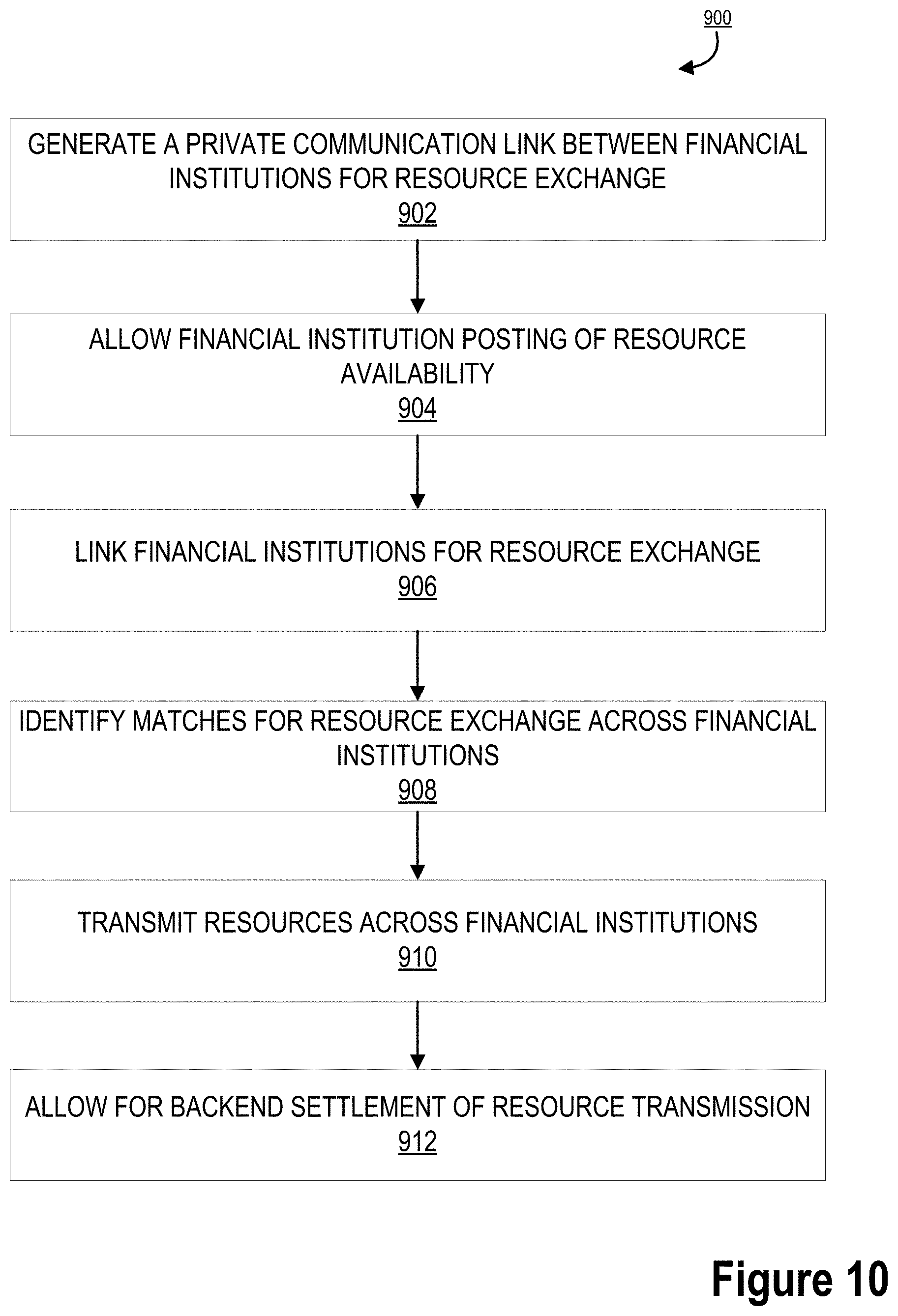
[0106] FIG. 10 provides a process map illustrating an entity resource exchange system 900, in accordance with one embodiment of the present invention. As illustrated in block 902, the process 900 is initiated by generating a private communication link between financial institutions for resource exchange between ATMs, branches, or the like. Once the communication channel is created and each financial institution within the system has access to a tool or portal, the system may allow for financial institution posting of resource availability or needs, as illustrated in block 904.
[0107] Next, as illustrated in block 906, the process 900 continues by linking the financial institutions for the resource exchange. This linkage is generated within a portal for distribution of resources across participating financial institutions. As illustrated in block 908, the system may identify a match between two financial institutions that each have a need for resource denominations that the other has. As such, the system may identify a match between two institutions for a resource exchange to occur between those two institutions. Next, the system may authorize transmission of the resources across the financial institutions, as illustrated in block 910. In this way, a vehicle may deliver cash in various requested denominations between two financial institutions based on the needs or requests from those institutions. Finally, as illustrated in block 912, the process 900 is completed by performing back-end settlement of the resource transmission for completion of the process.
[0108] As will be appreciated by one of ordinary skill in the art, the present invention may be embodied as an apparatus (including, for example, a system, a machine, a device, a computer program product, and/or the like), as a method (including, for example, a business process, a computer-implemented process, and/or the like), or as any combination of the foregoing. Accordingly, embodiments of the present invention may take the form of an entirely software embodiment (including firmware, resident software, micro-code, and the like), an entirely hardware embodiment, or an embodiment combining software and hardware aspects that may generally be referred to herein as a "system." Furthermore, embodiments of the present invention may take the form of a computer program product that includes a computer-readable storage medium having computer-executable program code portions stored therein. As used herein, a processor may be "configured to" perform a certain function in a variety of ways, including, for example, by having one or more special-purpose circuits perform the functions by executing one or more computer-executable program code portions embodied in a computer-readable medium, and/or having one or more application-specific circuits perform the function. As such, once the software and/or hardware of the claimed invention is implemented the computer device and application-specific circuits associated therewith are deemed specialized computer devices capable of improving technology associated with the in authorization and instant integration of a new credit card to digital wallets.
[0109] It will be understood that any suitable computer-readable medium may be utilized. The computer-readable medium may include, but is not limited to, a non-transitory computer-readable medium, such as a tangible electronic, magnetic, optical, infrared, electromagnetic, and/or semiconductor system, apparatus, and/or device. For example, in some embodiments, the non-transitory computer-readable medium includes a tangible medium such as a portable computer diskette, a hard disk, a random access memory (RAM), a read-only memory (ROM), an erasable programmable read-only memory (EPROM or Flash memory), a compact disc read-only memory (CD-ROM), and/or some other tangible optical and/or magnetic storage device. In other embodiments of the present invention, however, the computer-readable medium may be transitory, such as a propagation signal including computer-executable program code portions embodied therein.
[0110] It will also be understood that one or more computer-executable program code portions for carrying out the specialized operations of the present invention may be required on the specialized computer include object-oriented, scripted, and/or unscripted programming languages, such as, for example, Java, Perl, Smalltalk, C++, SAS, SQL, Python, Objective C, and/or the like. In some embodiments, the one or more computer-executable program code portions for carrying out operations of embodiments of the present invention are written in conventional procedural programming languages, such as the "C" programming languages and/or similar programming languages. The computer program code may alternatively or additionally be written in one or more multi-paradigm programming languages, such as, for example, F #.
[0111] It will further be understood that some embodiments of the present invention are described herein with reference to flowchart illustrations and/or block diagrams of systems, methods, and/or computer program products. It will be understood that each block included in the flowchart illustrations and/or block diagrams, and combinations of blocks included in the flowchart illustrations and/or block diagrams, may be implemented by one or more computer-executable program code portions. These one or more computer-executable program code portions may be provided to a processor of a special purpose computer for the authorization and instant integration of credit cards to a digital wallet, and/or some other programmable data processing apparatus in order to produce a particular machine, such that the one or more computer-executable program code portions, which execute via the processor of the computer and/or other programmable data processing apparatus, create mechanisms for implementing the steps and/or functions represented by the flowchart(s) and/or block diagram block(s).
[0112] It will also be understood that the one or more computer-executable program code portions may be stored in a transitory or non-transitory computer-readable medium (e.g., a memory, and the like) that can direct a computer and/or other programmable data processing apparatus to function in a particular manner, such that the computer-executable program code portions stored in the computer-readable medium produce an article of manufacture, including instruction mechanisms which implement the steps and/or functions specified in the flowchart(s) and/or block diagram block(s).
[0113] The one or more computer-executable program code portions may also be loaded onto a computer and/or other programmable data processing apparatus to cause a series of operational steps to be performed on the computer and/or other programmable apparatus. In some embodiments, this produces a computer-implemented process such that the one or more computer-executable program code portions which execute on the computer and/or other programmable apparatus provide operational steps to implement the steps specified in the flowchart(s) and/or the functions specified in the block diagram block(s). Alternatively, computer-implemented steps may be combined with operator and/or human-implemented steps in order to carry out an embodiment of the present invention.
[0114] While certain exemplary embodiments have been described and shown in the accompanying drawings, it is to be understood that such embodiments are merely illustrative of, and not restrictive on, the broad invention, and that this invention not be limited to the specific constructions and arrangements shown and described, since various other changes, combinations, omissions, modifications and substitutions, in addition to those set forth in the above paragraphs, are possible. Those skilled in the art will appreciate that various adaptations and modifications of the just described embodiments can be configured without departing from the scope and spirit of the invention. Therefore, it is to be understood that, within the scope of the appended claims, the invention may be practiced other than as specifically described herein.
* * * * *
D00000
D00001
D00002
D00003
D00004
D00005
D00006
D00007
D00008
D00009
D00010
XML
uspto.report is an independent third-party trademark research tool that is not affiliated, endorsed, or sponsored by the United States Patent and Trademark Office (USPTO) or any other governmental organization. The information provided by uspto.report is based on publicly available data at the time of writing and is intended for informational purposes only.
While we strive to provide accurate and up-to-date information, we do not guarantee the accuracy, completeness, reliability, or suitability of the information displayed on this site. The use of this site is at your own risk. Any reliance you place on such information is therefore strictly at your own risk.
All official trademark data, including owner information, should be verified by visiting the official USPTO website at www.uspto.gov. This site is not intended to replace professional legal advice and should not be used as a substitute for consulting with a legal professional who is knowledgeable about trademark law.