Fixed Iron Sight And Accessories
Shelton; Derek Hunter ; et al.
U.S. patent application number 16/667412 was filed with the patent office on 2020-04-30 for fixed iron sight and accessories. This patent application is currently assigned to RAILSCALES LLC. The applicant listed for this patent is RAILSCALES LLC. Invention is credited to Brent Taylor McGuire, Derek Hunter Shelton.
| Application Number | 20200132414 16/667412 |
| Document ID | / |
| Family ID | 70326451 |
| Filed Date | 2020-04-30 |


View All Diagrams
| United States Patent Application | 20200132414 |
| Kind Code | A1 |
| Shelton; Derek Hunter ; et al. | April 30, 2020 |
FIXED IRON SIGHT AND ACCESSORIES
Abstract
A raised iron sight assembly is provided. The raised iron sight assembly includes a raised iron sight portion with a base portion, a neck extending from the base portion, and a sight portion. The base portion includes at least one recoil lug configured to straddle at least one recoil groove on a firearm rail system. The raised iron sight assembly includes a latch portion configured to selectively attach to the raised iron sight portion.
| Inventors: | Shelton; Derek Hunter; (Claremore, OK) ; McGuire; Brent Taylor; (Depew, OK) | ||||||||||
| Applicant: |
|
||||||||||
|---|---|---|---|---|---|---|---|---|---|---|---|
| Assignee: | RAILSCALES LLC Claremore OK |
||||||||||
| Family ID: | 70326451 | ||||||||||
| Appl. No.: | 16/667412 | ||||||||||
| Filed: | October 29, 2019 |
Related U.S. Patent Documents
| Application Number | Filing Date | Patent Number | ||
|---|---|---|---|---|
| 62752072 | Oct 29, 2018 | |||
| Current U.S. Class: | 1/1 |
| Current CPC Class: | F41G 1/033 20130101; F41G 11/003 20130101 |
| International Class: | F41G 1/033 20060101 F41G001/033; F41G 11/00 20060101 F41G011/00 |
Claims
1. A raised iron sight assembly, comprising: a raised iron sight portion comprising a base portion, a neck extending from the base portion, and a sight portion, the base portion comprising at least one recoil lug configured to straddle at least one recoil groove on a firearm rail system; and a latch portion configured to selectively attach to the raised iron sight portion.
2. The raised iron sight assembly of claim 1, wherein the base portion comprises a first clamp arm configured to partially wrap a mounting rail of the firearm rail system.
3. The raised iron sight assembly of claim 1, wherein the latch portion comprises a second clamp arm configured to partially wrap a mounting rail of the firearm rail system.
4. The raised iron sight assembly of claim 1, wherein the base portion and the latch portion comprise a set of arms configured to secure the raised iron sight assembly to a mounting rail of the firearm rail system.
5. The raised iron sight assembly of claim 1, further comprising an iron sight post disposed in a plurality of sight adjustment apertures on the sight portion.
6. The raised iron sight assembly of claim 5, wherein the sight adjustment apertures disposed on the sight portion are configured to receive a set of detents to secure the iron sight post.
7. The raised iron sight assembly of claim 5, wherein the sight comprises: a disc having a first side, a second side, and an edge; a series of arcuate indentions disposed on the edge of the disc; and one or more detents extending from the first side and the second side of the disc.
8. The raised iron sight assembly of claim 1, wherein the neck comprises at least one flattened side and an arcuate side.
9. The raised iron sight assembly of claim 1, wherein the sight portion comprises: a floor; and at least two walls coupled to the floor, wherein the at least two walls extend away from the neck.
10. The raised iron sight assembly of claim 1, wherein the base portion comprises a first lug arm and a second lug arm, wherein the at least one recoil lug is disposed on the first lug arm and the second lug arm.
11. The raised iron sight assembly of claim 1, further comprising one or more fasteners securing the latch portion to the raised iron sight portion.
12. A raised iron sight, comprising: a base portion comprising a first clamp arm and a set of lug arms configured to secure the base portion to a firearm rail system; a latch portion coupled to the base portion, wherein the latch portion comprises a second clamp arm configured to secure the base portion to the firearm rail system; a neck extending from the base portion; and a sight portion extending from the neck.
13. The raised iron sight of claim 12, wherein the sight portion, the base portion, and the latch portion comprise a plurality of sight adjustment apertures or a clamp aperture.
14. The raised iron sight of claim 13, further comprising a fastener configured to secure the latch portion to the base portion.
15. The raised iron sight of claim 13, wherein the sight portion comprises an iron sight post configured to be embedded in at least one sight adjustment aperture.
16. The raised iron sight of claim 15, wherein the sight comprises: a disc; one or more detents configured to secure the sight into at least one aperture in the plurality of apertures; and a series of arcuate indentions on the disc.
17. The raised iron sight of claim 13, wherein the sight portion comprises a floor coupled to at least two walls extending therefrom.
18. The raised iron sight of claim 12, wherein the neck comprises at least one flat side and at least one arcuate side.
19. A raised iron sight assembly, comprising: a raised iron sight portion comprising a base portion, a neck extending from the base portion, and a sight portion, the base portion comprising: at least one recoil lug configured to straddle at least one recoil groove on a firearm rail system; and a first clamp arm configured to partially wrap a mounting rail of the firearm rail system; and a latch portion comprising a second clamp arm configured to partially wrap a mounting rail of the firearm rail system.
20. The raised iron sight of claim 19, wherein the neck comprises at least one flat side and at least one arcuate side.
Description
CROSS-REFERENCE TO RELATED APPLICATIONS
[0001] This application claims priority and benefit of U.S. Provisional Application 62/752,072, filed on Oct. 29, 2018, which is incorporated by reference herein in its entirety.
FIELD OF DISCLOSURE
[0002] The present application relates generally to firearm sights, and more specifically, relates to a firearm sight configured to mount onto a firearm rail system.
BACKGROUND
[0003] Firearm sights come in many different sizes, shapes, and materials. Sights can be as simple as an iron sight or as complex as a laser sight. Each type of sight has its set of benefits as well as its set of drawbacks. As may be desired from time to time, the typical firearm enthusiast may enjoy using two or more of the sights on his or her firearm to compensate for each firearm sight's failings. For instance, multiple firearm sights may be mounted to a firearm rail system or firearm slide to alternate between depending on the range of the target. However, often mounting multiple firearm sights actually inhibits the firearm enthusiast's aim because of a crowded line of sight down the barrel of the firearm. Thus, any improvement in firearm sight mounting configurations or structure could improve the issue of crowding and lead to a plurality of different options for mounting multiple firearm sights.
BRIEF DESCRIPTION OF THE DRAWINGS
[0004] Referring now to the drawings, which are meant to be exemplary and not limiting, and wherein like elements are numbered alike. The detailed description is set forth with reference to the accompanying drawings illustrating examples of the disclosure, in which use of the same reference numerals indicates similar or identical items. Certain embodiments of the present disclosure may include elements, components, and/or configurations other than those illustrated in the drawings, and some of the elements, components, and/or configurations illustrated in the drawings may not be present in certain embodiments.
[0005] FIG. 1A is a perspective view of the raised iron sight assembly mounted to the rail system according to one or more embodiments of the disclosure.
[0006] FIG. 1B is a front view of the raised iron sight assembly mounted to the rail system according to one or more embodiments of the disclosure.
[0007] FIG. 1C is a perspective view of the raised iron sight coupled to the rail system according to one or more embodiments of the disclosure.
[0008] FIG. 1D is a top perspective view of the rail system and a firearm laser optic according to one or more embodiments of the disclosure.
[0009] FIG. 2A is a side perspective view of the raised iron sight assembly mounted to a rail system according to one or more embodiments of the disclosure.
[0010] FIG. 2B is a front view of a raised iron sight assembly according to one or more embodiments of the disclosure.
[0011] FIG. 2C is a right side view of the raised iron sight assembly according to one or more embodiments of the disclosure.
[0012] FIG. 2D is a rear view of the raised iron sight assembly according to one or more embodiments of the disclosure.
[0013] FIG. 2E is a left side view of the raised iron sight assembly according to one or more embodiments of the disclosure.
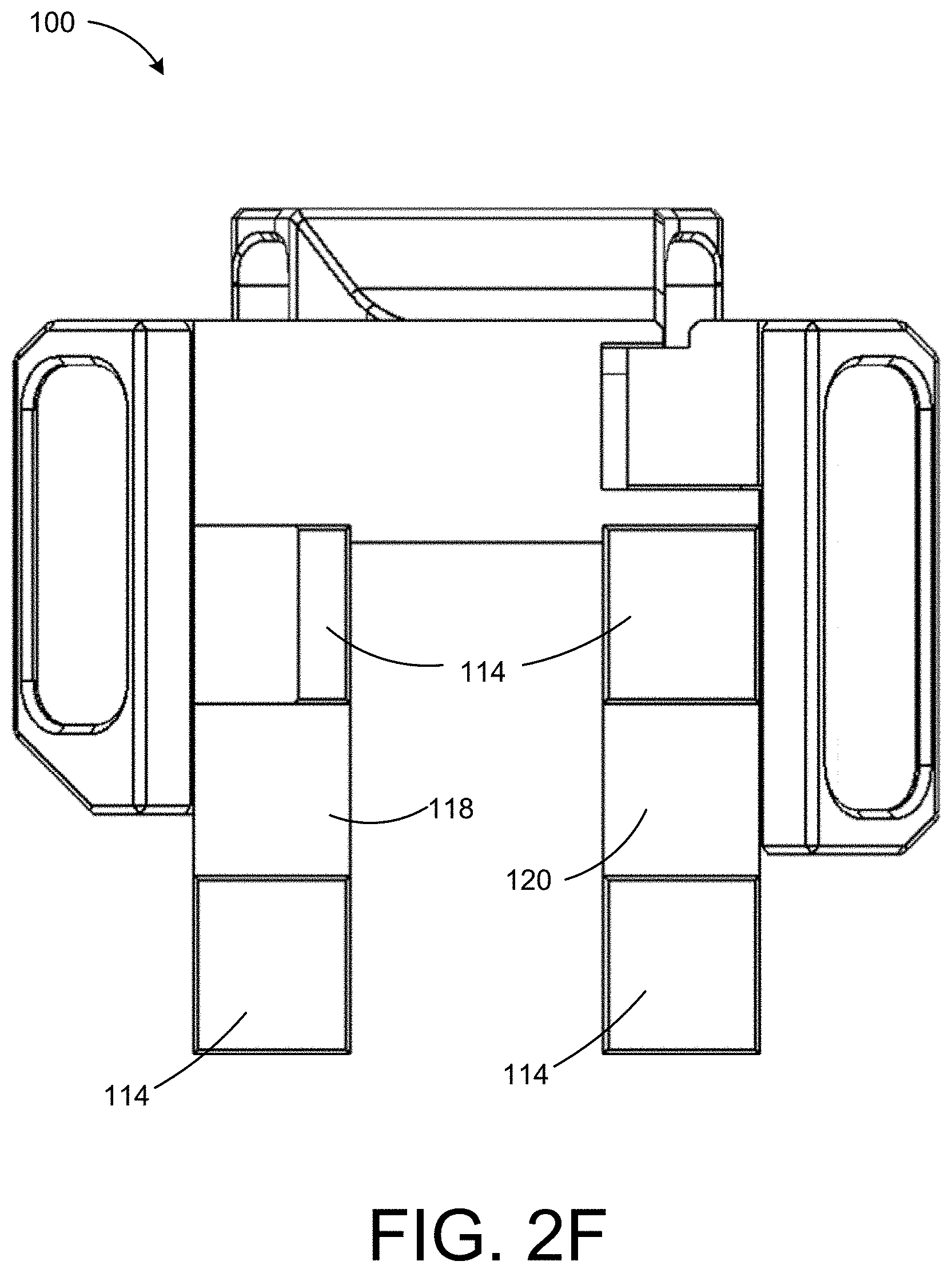
[0014] FIG. 2F is a bottom view of the raised iron sight assembly according to one or more embodiments of the disclosure.
[0015] FIG. 2G is a top view of the raised iron sight assembly according to one or more embodiments of the disclosure.
[0016] FIG. 3A is a front view of a raised iron sight portion of the raised iron sight assembly according to one or more embodiments of the disclosure.
[0017] FIG. 3B is a right side view of the raised iron sight portion of the raised iron sight assembly according to one or more embodiments of the disclosure.
[0018] FIG. 3C is a rear view of the raised iron sight portion of the raised iron sight assembly according to one or more embodiments of the disclosure.
[0019] FIG. 3D is a top view of the raised iron sight portion of the raised iron sight assembly according to one or more embodiments of the disclosure.
[0020] FIG. 4A is a front view of a latch portion of the raised iron sight assembly according to one or more embodiments of the disclosure.
[0021] FIG. 4B is a right side view of the latch portion of the raised iron sight assembly according to one or more embodiments of the disclosure.
[0022] FIG. 5 is a perspective view of a bolt according to one or more embodiments of the disclosure.
[0023] FIG. 6 is a perspective view of an iron sight post according to one or more embodiments of the disclosure.
[0024] FIG. 7 is a perspective view of a fastener according to one or more embodiments of the disclosure.
DETAILED DESCRIPTION
[0025] The present disclosure provides for a raised iron sight assembly. The raised iron sight assembly is a fixed adjustable front sight configured to attach to a rail system (e.g., a picatinny rail system). One benefit to the raised iron sight assembly may include decreasing the footprint of an iron sight mounted onto a rail system as well as decreasing the footprint of other accessories mounted onto the same rail. For example, the raised iron sight may be configured to complement the shape of another accessory (e.g., an AN/PEQ15 ATPIAL series laser system). As such, the raised iron sight and the other accessory mount onto a rail system with a smaller overall footprint relative to other, on the market fixed sights.
[0026] FIG. 1A depicts a raised iron sight assembly 100 secured onto a firearm rail 160 between components of a laser optic 154. In this manner, the raised iron sight is shaped to fit between the aiming laser and infrared illuminator of the laser optic 154. One benefit of mounting between the laser accessory components is a reduction of the infrared splash. As used herein, the phrase "infrared splash" denotes the amount of infrared waves deflected from a particular object. For example, an iron sight mounted in front of the infrared illuminator will create an infrared splash, and in turn, increases the firearm's infrared signature. Conversely, as shown and improved here, an iron sight configured to recede behind where the lasers project will relatively diminish any resulting infrared splash from the raised iron sight.
[0027] As shown in FIG. 1C, the raised iron sight assembly 100 is fixed to recoil grooves 116 of the rail system 160. As used herein, the phrase "firearm rail system" refers to a series of grooves and ribs disposed adjacent to the barrel of a firearm and may include any one of the following type of rail system: PWS Mod 1/Mod 2rail, BOOTLEG, INC. rail, BCM KMR/MMR, AAC Teardrop, GEISSELE 4 sided rail, DANIEL DEFENSE Slim rail, MIDWEST SSK/SSM, MIDWEST G3KL/G3ML, CMMG Rails Keymod/M-LOK, DAKOTA TACTICAL HK Series Keymod/M-LOK, VLTOR FREEDOM rail, PARKER MOUNTAIN MACHINE SCAR rail, KNS BREN 805 rail, HK Parts HK rail, NOVESKE NSR, NOVESKE NHR, NOVESKE NSRM, SMOS ARMS, or KAC URX 4 Keymod/M-LOK. The raised iron sight assembly 100 is positioned onto the rail system 160 to fit within the receded portion of a laser optic 154 (e.g., an ATPIAL laser) between the visible aiming laser and the infrared illuminator. For example, a neck 106 of the raised iron sight assembly 100 includes an arcuate side and a flattened side. Two benefits of modeling an iron sight to fit between the visible aiming laser and infrared illuminator of the laser optic 154 includes reducing the footprint of both sights as well as reducing infrared splash discussed previously. A benefit of reducing the footprint is twofold. First, a user can quickly adjust between which optic to use, and second, the user can fit more tools onto the firearm rail.
[0028] Various views of the raised iron sight assembly are shown in FIGS. 2A-2G. The raised iron sight assembly includes a raised iron sight portion 102 and a latch 126 configured to operably attach to the raised iron sight portion 102. The raised iron sight portion includes a base portion 104, a neck 106 extending from the base portion 104, and a sight portion 108. The base portion 104 may be configured to reduce the raised iron sight assembly's footprint on the firearm rail as well as help to further secure the raised iron sight assembly by at least one recoil lug extending therefrom into a recoil groove on the firearm rail system. The compact shape and size of the raised iron sight assembly may be configured to fit between the laser components of an ATPIAL or other firearm optic as described herein. The compact configuration may place the ATPIAL unit six picatinny slots closer to the muzzle, and thus having a smaller overall footprint.
[0029] The base portion 104, the neck 106, and the sight portion 108 can form a unitary structure. In other embodiments, each portion of the raised iron sight portion 102 may separate into separate components. For example, each portion may selectively attach to one another by adhesive, fasteners, or other attachment means. The raised iron sight assembly 100 may be composed of 7075-T6 aluminum and finished with a hard coat anodizing. In other instances, the raised iron sight assembly 100 may be composed of a metal or metal alloy, such as stainless steel, iron, or some other material. In yet other instances, the raised iron sight portion 102 may be composed of a plastic composite.
[0030] FIG. 2F depicts a bottom view of the raised iron sight assembly 100. As shown, the base portion 104 is configured to grapple at least one side of the firearm rail system 160. For example, the base portion 104 includes a series of arms and clamps (i.e., a first clamp arm 122, a first lug arm 118, and a second lug arm 120) as well as at least one recoil lug 114 configured to restrict movement of the raised iron sight assembly 100.
[0031] The base portion 104 includes the first lug arm 118 and the second lug arm 120 extending in a perpendicular direction as the raised iron sight portion 102. In other embodiments, the first lug arm 118 and the second lug arm 120 may extend in a different direction from the raised iron sight portion 102, such as in a parallel or angled direction. For example, the first lug arm 118 and second lug arm 120 may extend at a 30 degree angle from the raised iron sight portion 102. In other instances, the first lug arm 118 and second lug arm 120 may extend at an angle less than 30 degrees or greater than 30 degrees. In some embodiments, the first lug arm 118 and the second lug arm 120 extend under a laser accessory coupled to the firearm rail (e.g., as shown in FIG. 1A) thereby securing the raised iron sight to the firearm rail. That is, each of the recoil lug arms engage with the recoil grooves 116. In other instances, the recoil lugs arm engage another component of firearm rail system 160.
[0032] The first lug arm 118 and the second lug arm 120 include recoil lug(s) 114 extending from the lug arms 118/120 of the base portion 104. The recoil lug(s) 114 may extend from another portion of the raised iron sight portion 102. The recoil lug(s) 114 are configured to set within one of the recoil grooves 116 (as seen in FIG. 1A) of the firearm rail system 160. The recoil lug(s) 114 prevent movement of the raised iron sight assembly 100 from lateral movement during the discharge of a firearm. The recoil lug(s) 114 may be rectangular protrusions extending from the bottom of the base portion 104 of the raised iron sight assembly 100. In other instances, the recoil lug(s) 114 may be circular, square, pyramidal, or some other shape. The lugs may be the same shape or may be a different shape from one another. The recoil lug(s) 114 may complement the shape of the recoil grooves 116 on the firearm rail system 160. In some instances, two lugs extend from each lug arm of the base portion 104. In other instances, one lug extends from each arm of the base portion 104. In other instances, more than two lugs extend from each arm of the base portion. As depicted in FIG. 2F, the first lug arm 118 and the second lug arm 120 have the same number of recoil lugs. Each lug on the lug arms includes a complementary lug on the other arm to secure the raised iron sight assembly onto a firearm rail 160. In other embodiments, each lug may not have a complementary lug on the opposite arm.
[0033] As shown in FIG. 2A, the base portion 104 includes a first clamp arm 122 configured to restrict lateral movement of the raised iron sight assembly 100. For example, the first clamp arm 122 applies a normal force to the firearm rail system in the direction of a second clamp arm 124. The first clamp arm 122 includes a first leg 162 (i.e., first section) that extends away from the base portion 104 and a second leg 164 turns 90 degrees away from the first leg 162. In other instances, the second leg 164 may form a different angle. As shown in FIG. 1A, the first clamp arm 122 is configured to partially wrap a side of the mounting rail of the firearm rail system. As used herein, the term "partially" means the emphasized verb is limited. In some instances, the first clamp arm 122 may fully wrap around the firearm rail system. The first clamp arm 122 may attach to an aperture of the firearm rail system, such as an M-LOK system.
[0034] In some embodiments, the raised iron sight portion 102 includes a neck 106 extending from the base portion 104. For example, the neck 106 is an elongated structure configured to extend above a firearm laser optic mounted onto a firearm rail (e.g., as depicted in FIG. 1A). The neck 106 extends above the laser to place the iron sight post in the firearm line of sight. In some embodiments, as depicted in FIG. 2B, the neck 106 has an arcuate side 130 and at least one flattened side 132. For example, the arcuate side 130 may be configured to place the raised iron sight portion 102 adjacent to a laser sight. One benefit to the raised iron sight assembly having an asymmetrical shape includes using space on the firearm rail in an efficient manner. In other embodiments, the neck 106 may have a symmetrical shape (i.e., all sides arcuate or all sides flattened). The neck 106 includes more than one flattened side 132. For example, the neck 106 includes at least three flattened sides 132. In some instances, the neck 106 may have more or less than three flattened sides 132. In some instances, the neck 106 may have a plurality of indentions 158 and apertures (not shown) disposed along each side. Some of the apertures may receive a fastener or another portion of the raised iron sight assembly 100. Additionally, some of the indentions are disposed along the neck 106 to reduce weight and reduce the amount of material used to mold the raised iron sight assembly 100.
[0035] In some embodiments, the raised iron sight portion 102 includes a sight portion 108 configured to receive an iron sight post 134. For example, the sight portion 108 may include at least one sight adjustment aperture 156 configured to receive the iron sight post 134 and a set of smooth detents 150 configured to adjust the iron sight post 134. In some instances, the sight adjustment apertures 156 on the sight portion 108 may receive other fasteners to secure the iron sight post 134. The sight portion 108 may extend from the neck 106 to extend above a laser optic (e.g., ATPIAL laser) to place the sight post 134 in a users line of sight. In some embodiments the sight portion 108 may extend from the base portion 104 or another portion of the raised iron sight portion 102. In some embodiments, the sight portion 108 includes a floor 136 and at least two walls 138 coupled to the floor 136. The floor 136 may be parallel with a firearm's barrel once the raised iron sight assembly 100 is mounted. For example, the floor 136 may be parallel to increase accuracy of the sight 134 (or iron sight post) coupled to the floor 136. In some instances, at least two walls 138 extend perpendicularly from the floor 136. For example, the at least two walls 138 may extend at an equal distance from the sight 134 within the floor. One benefit of the two walls 138 forming a symmetrical shape is to improve centering of the sight 134 onto a target. In some instances, the at least two walls 138 may not be symmetrical. In some instances, more than two walls may extend from the floor 136 and/or neck 106. The at least two walls 138 may be flat on the side facing the sight 134. In some instances, the at least two walls 138 may be the same height as the sight 134. In other instances, the at least two walls 138 may not be flat. In other instances, the at least two walls 138 may not be the same height as the sight 134.
[0036] A raised iron sight portion 102 is depicted in FIGS. 3A-3D. The raised iron sight portion 102 includes a plurality of apertures (i.e., at least one clamp aperture 110 and at least one sight adjustment aperture 156) and a plurality of indentions 158. The plurality of indentions 158 may be disposed about the raised iron sight assembly 100 to reduce weight of the assembly. In other instances, the raised iron sight assembly 100 may not include indentions. In yet other instances, the indentions 158 may accept other accessories or firearm attachments.
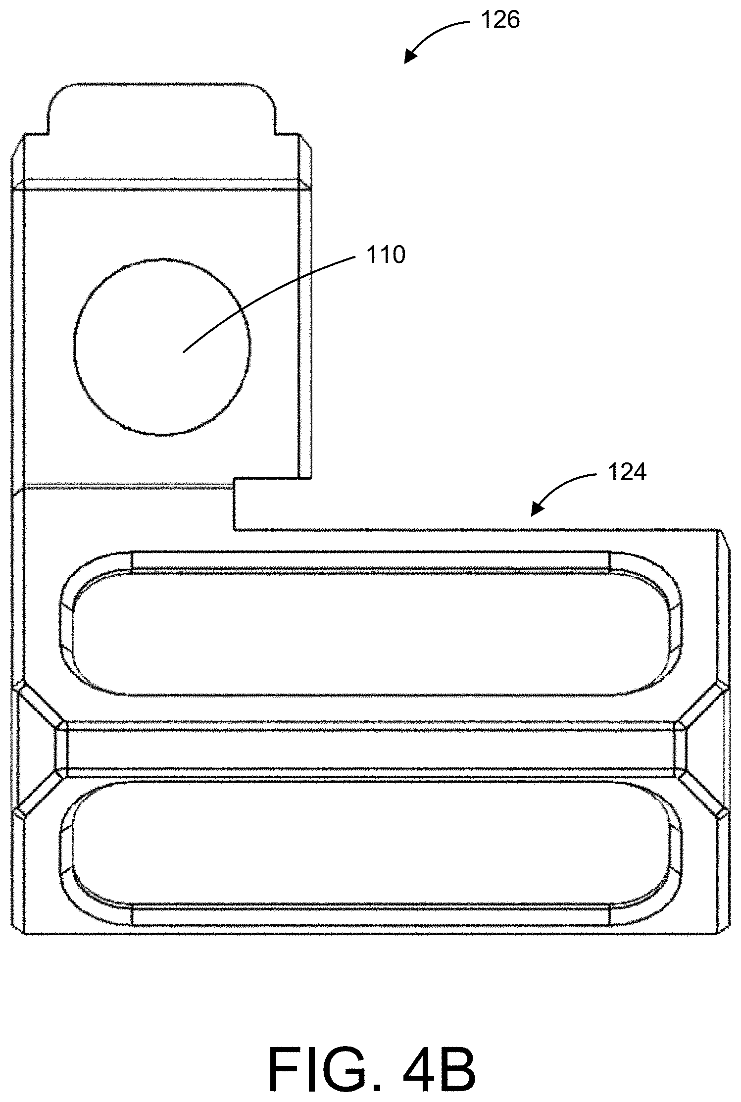
[0037] In some embodiments, the raised iron sight assembly 100 includes a latch 126 as shown in FIGS. 4A and 4B. The latch 126 is configured to secure the raised iron sight portion 102 to the firearm rail system. For example, the latch 126 may work in tandem with the first clamp arm 122 to secure the raised iron sight assembly 100. For example, the latch 126 may include a one or more arms (i.e., a second lug arm and a second clamp arm 124) to restrict movement of the raised iron sight assembly 100. In some instances, latch 126 may be the portion of the raised iron sight assembly 100 along with the base portion 104 contacting the firearm rail system. In other instances, the latch 126 may be positioned elsewhere along the raised iron sight portion 102. In some embodiments, as seen in FIG. 4B, the latch 126 includes at least one clamp aperture 110. The at least one clamp aperture 110 may be configured to receive a fastener 112 (e.g., as shown in FIG. 5). The latch 126 and the fastener 112 may secure to the raised iron sight portion 102 at the base portion 104. In other instances, the latch 126 may secure onto a different portion of the raised iron sight assembly 100. In some instances, the latch 126 may mimic every feature of the base portion 104 to form a symmetrical shape for the base of the raised iron sight assembly 100. In other instances, the latch 126 may form an asymmetrical shape with the base portion 104.
[0038] In some embodiments, latch 126 includes a second clamp arm 124 configured to restrict movement of the raised iron sight assembly 100. For example, the second clamp arm 124 may apply a normal force to the firearm rail system in the direction of a first clamp arm 122 of the raised iron sight portion 102. In some instances, the second clamp arm 124 may apply a force in a different direction than the firearm rail system. As depicted in FIG. 4A, the second clamp arm 124 includes a second clamp arm first leg 127 (i.e., first section) that extends away from the latch 126, then a second clamp arm second leg 129 turns 90 degrees away from the first leg. In some instances, the second clamp arm first leg 127 and second clamp arm second leg 129 may form a different angle. The second clamp arm 124 may be configured to partially wrap a side of the mounting rail of the firearm rail system. In other instances, the first clamp arm 122 may wrap around the firearm rail system. In other instances, the second clamp arm 124 may attach to an aperture of the firearm rail system.
[0039] In some embodiments, the at least one clamp aperture 110 is configured to accept a fastener 112 (e.g., as seen in FIG. 2A). The fastener 112 is configured to thread through the latch 126 into the clamp aperture 110. In some instances, the fastener 112 may have a hexagonal aperture configured to receive a hex key. In other instances, the fastener 112 may have an aperture configured to receive another type of screwdriver, such as a Philips head, flat head or some other type of screwdriver head. In some instances, the fastener 112 may be a bolt. In other instances, the fastener 112 may be a nut and bolt, screw, hook and loop, snap, or other type of fastener. In some instances, the clamp aperture 110 may be threaded. In other instances, the at least one clamp aperture 110 may be smooth. The fastener to be accepted by the aperture may be composed of heat treated, black oxide coated stainless steel. In other instances, the fastener may be composed of aluminum, steel, iron, or some other alloy.
[0040] FIG. 6 depicts a sight 134 of the raised iron sight assembly 100. The sight 134 is configured to be mounted within the floor 136 of the sight portion 108 (e.g., as shown in FIG. 2A). For example, the sight 134 may include a disc 140 with a first side 146 and a second side 148. The disc 140 of the sight 134 may complement an aperture within the floor 136 of the sight portion 108. The disc 140 may be round. In other instances, the disc 140 may be rectangular, triangular, oval, or some other shape. In some instances, the disc 140 may have a series of arcuate indentions 142 configured to be received by the aperture on the floor 136 of the sight portion 108. The series of arcuate indentions 142 may be configured to partially fit other fasteners (e.g., a smooth detent 150 as seen in FIG. 2G) setting within the floor 136. One benefit of the additional fasteners within the arcuate indentions 142 is preventing unwanted rotation of the sight 134. For example, each smooth detent 150 may be set upon a compression spring within the sight adjustment apertures 156 of FIG. 3D. The smooth detent(s) 150 may be configured to click into place within the arcuate indentions 142 of the sight 134. In addition, the sight 134 may have a plurality of indexing dots 152. The indexing dots 152 may be configured to receive paint fill to indicate the sights' 134 confirmed zero. In other instances, the disc 140 may not have the series of arcuate indentions 142.
[0041] In some embodiments, one or more detents 144 may extend from the first side 146 and the second side 148 of the sight 134. For example, from the first side 146, a first detent 144A may extend therefrom and be configured to provide a front sight view for a firearm user. In some instances, the first detent 144A may be rectangular. In other instances, the first detent 144A may be circular, triangular, or some other shape. In some embodiments, the second detent 144B extends from the second side 148. The second detent 144B may be configured to be accepted by an aperture in the floor 136. The second detent 144B may be threaded or smooth. The second detent 144B may be circular, rectangular, triangular, or some other shape.
[0042] Although specific embodiments of the disclosure have been described, numerous other modifications and alternative embodiments are within the scope of the disclosure. For example, any of the functionality described with respect to a particular device or component may be performed by another device or component. Further, while specific device characteristics have been described, embodiments of the disclosure may relate to numerous other device characteristics. Further, although embodiments have been described in language specific to structural features and/or methodological acts, it is to be understood that the disclosure is not necessarily limited to the specific features or acts described. Rather, the specific features and acts are disclosed as illustrative forms of implementing the embodiments. Conditional language, such as, among others, "can," "could," "might," or "may," unless specifically stated otherwise, or otherwise understood within the context as used, is generally intended to convey that certain embodiments could include, while other embodiments may not include, certain features, elements, and/or steps. Thus, such conditional language is not generally intended to imply that features, elements, and/or steps are in any way required for one or more embodiments.
* * * * *
D00000
D00001
D00002
D00003
D00004
D00005
D00006
D00007
D00008
D00009
D00010
D00011
D00012

D00013

D00014

D00015

D00016

D00017
D00018

D00019

D00020

XML
uspto.report is an independent third-party trademark research tool that is not affiliated, endorsed, or sponsored by the United States Patent and Trademark Office (USPTO) or any other governmental organization. The information provided by uspto.report is based on publicly available data at the time of writing and is intended for informational purposes only.
While we strive to provide accurate and up-to-date information, we do not guarantee the accuracy, completeness, reliability, or suitability of the information displayed on this site. The use of this site is at your own risk. Any reliance you place on such information is therefore strictly at your own risk.
All official trademark data, including owner information, should be verified by visiting the official USPTO website at www.uspto.gov. This site is not intended to replace professional legal advice and should not be used as a substitute for consulting with a legal professional who is knowledgeable about trademark law.