Cooling Device
CHENG; Tsai-Kuei ; et al.
U.S. patent application number 16/198551 was filed with the patent office on 2020-04-30 for cooling device. This patent application is currently assigned to INVENTEC (PUDONG) TECHNOLOGY CORPORATION. The applicant listed for this patent is INVENTEC (PUDONG) TECHNOLOGY CORPORATION INVENTEC CORPORATION. Invention is credited to Hung-Ju CHEN, Tsai-Kuei CHENG.
| Application Number | 20200132388 16/198551 |
| Document ID | / |
| Family ID | 64875392 |
| Filed Date | 2020-04-30 |


| United States Patent Application | 20200132388 |
| Kind Code | A1 |
| CHENG; Tsai-Kuei ; et al. | April 30, 2020 |
COOLING DEVICE
Abstract
A cooling device is configured to cool a heat source. The cooling device includes a tank, a cover and a cooling liquid. The tank includes a bottom surface, a tank inlet and a tank outlet. The cover is disposed on the tank. The cover and the tank form a space therebetween, and the space is configured to accommodate the heat source. The cooling liquid is located in the space.
| Inventors: | CHENG; Tsai-Kuei; (Taipei City, TW) ; CHEN; Hung-Ju; (Taipei City, TW) | ||||||||||
| Applicant: |
|
||||||||||
|---|---|---|---|---|---|---|---|---|---|---|---|
| Assignee: | INVENTEC (PUDONG) TECHNOLOGY
CORPORATION Shanghai City CN INVENTEC CORPORATION Taipei City TW |
||||||||||
| Family ID: | 64875392 | ||||||||||
| Appl. No.: | 16/198551 | ||||||||||
| Filed: | November 21, 2018 |
| Current U.S. Class: | 1/1 |
| Current CPC Class: | F28D 2021/0028 20130101; F28D 15/025 20130101; F28D 15/0266 20130101 |
| International Class: | F28D 15/02 20060101 F28D015/02 |
Foreign Application Data
| Date | Code | Application Number |
|---|---|---|
| Oct 26, 2018 | CN | 201811263995.5 |
Claims
1. A cooling device, configured to cool a heat source, comprising: a tank, including a bottom surface, a tank inlet and a tank outlet; a cover, disposed on the tank, the cover and the tank forming a space therebetween, and the space configured to accommodate the heat source; and a cooling liquid, located in the space.
2. The cooling device according to claim 1, wherein the tank inlet of the tank is closer to the bottom surface of the tank than the tank outlet.
3. The cooling device according to claim 2, further comprising a liquid channel and a vapor channel, the liquid channel connected to the tank via the tank inlet, and the vapor channel connected to the tank via the tank outlet.
4. The cooling device according to claim 3, wherein the vapor channel includes an inlet end and an outlet end, the inlet end is connected to the tank outlet of the tank, and the inlet end is closer to the bottom surface of the tank than the outlet end.
5. The cooling device according to claim 4, wherein the cover includes a first side and a second side, the first side is closer to the tank outlet of the tank than the second side, and the first side is farther away from the bottom surface of the tank than the second side.
6. The cooling device according to claim 3, further comprising a heat exchange portion, wherein the vapor channel is connected to the liquid channel via the heat exchange portion.
7. The cooling device according to claim 6, further comprising a heat dissipation device connected to the heat exchange portion.
8. The cooling device according to claim 1, further comprising an electrical connector connected to the cover, wherein the electrical connector is configured to be electrically connected to the heat source.
9. The cooling device according to claim 1, further comprising a liquid pump device connected to the tank.
10. The cooling device according to claim 1, further comprising an air pump device connected to the tank.
Description
CROSS-REFERENCE TO RELATED APPLICATIONS
[0001] This non-provisional application claims priority under 35 U.S.C. .sctn. 119(a) on Patent Application No(s). 201811263995.5 filed in China, P.R.C. on Oct. 26, 2018, the entire contents of which are hereby incorporated by reference.
TECHNICAL FIELD
[0002] The present disclosure relates to a cooling device, more particularly to a cooling device including a tank inlet and a tank outlet.
BACKGROUND
[0003] A common immersion cooling device includes a tank, which is divided to a liquid portion and a vapor portion. The liquid portion is located below the vapor portion and configured to accommodate a cooling liquid which is volatile and low boiling, and there is a heat dissipation device in the vapor portion. A server can be immersed into the cooling liquid for the cooling liquid to absorb heat generated by the server. A portion of the cooling liquid would evaporate into vapor by the heat. When the vapor flows to the vapor portion, the heat in the vapor can be removed by the heat dissipation device, the then the vapor is condensed into the cooling liquid and drops back to the liquid portion of the tank due to gravity.
SUMMARY
[0004] According to one aspect of the present disclosure, a cooling device is configured to cool a heat source. The cooling device includes a tank, a cover and a cooling liquid. The tank includes a bottom surface, a tank inlet and a tank outlet. The cover is disposed on the tank. The cover and the tank form a space therebetween, and the space is configured to accommodate the heat source. The cooling liquid is located in the space.
BRIEF DESCRIPTION OF THE DRAWINGS
[0005] The present disclosure will become more fully understood from the detailed description given hereinbelow and the accompanying drawings which are given by way of illustration only and thus are not intending to limit the present disclosure and wherein:
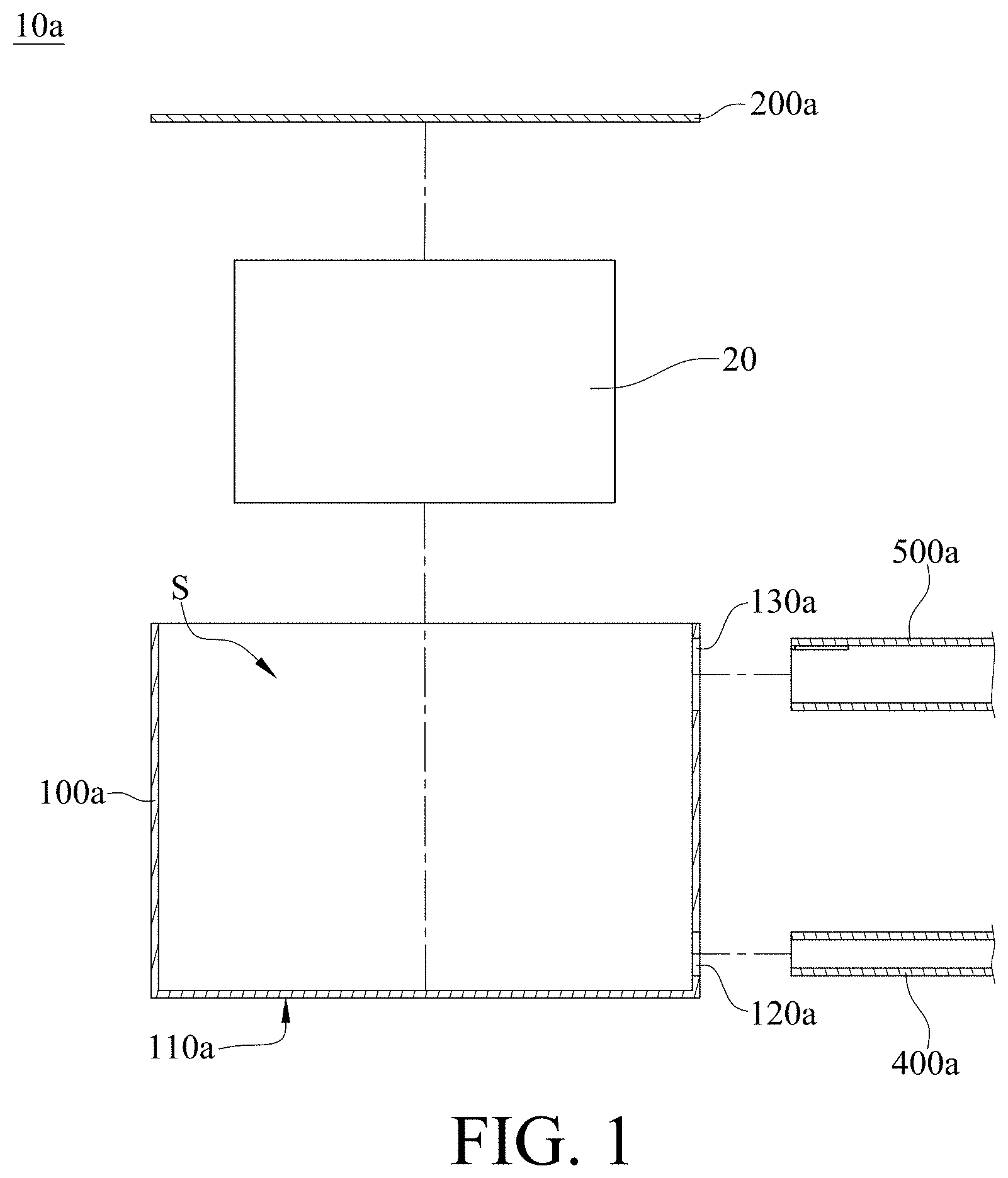
[0006] FIG. 1 is an exploded cross-sectional view of a cooling device and a heat source according to one embodiment of the present disclosure;
[0007] FIG. 2 is a cross-sectional view of the cooling device when the heat source is disposed in the cooling device;
[0008] FIG. 3 is a cross-sectional view of the cooling device during the operation of the heat source in FIG. 1;
[0009] FIG. 4 is a cross-sectional view of a cooling device according to another embodiment of the present disclosure during the operation of the heat source;
[0010] FIG. 5 is a cross-sectional view of a cooling device according to yet another embodiment of the present disclosure during the operation of the heat source;
[0011] FIG. 6 is a cross-sectional view of a cooling device according to still another embodiment of the present disclosure during the operation of the heat source;
[0012] FIG. 7 is a cross-sectional view of a cooling device according to still yet another embodiment of the present disclosure during the operation of the heat source;
[0013] FIG. 8 is a cross-sectional view of a cooling device according to still yet another embodiment of the present disclosure during the operation of the heat source;
[0014] FIG. 9 is a cross-sectional view of a cooling device according to still yet another embodiment of the present disclosure during the operation of the heat source;
[0015] FIG. 10 is a cross-sectional view of a cooling device according to still yet another embodiment of the present disclosure during the operation of the heat source; and
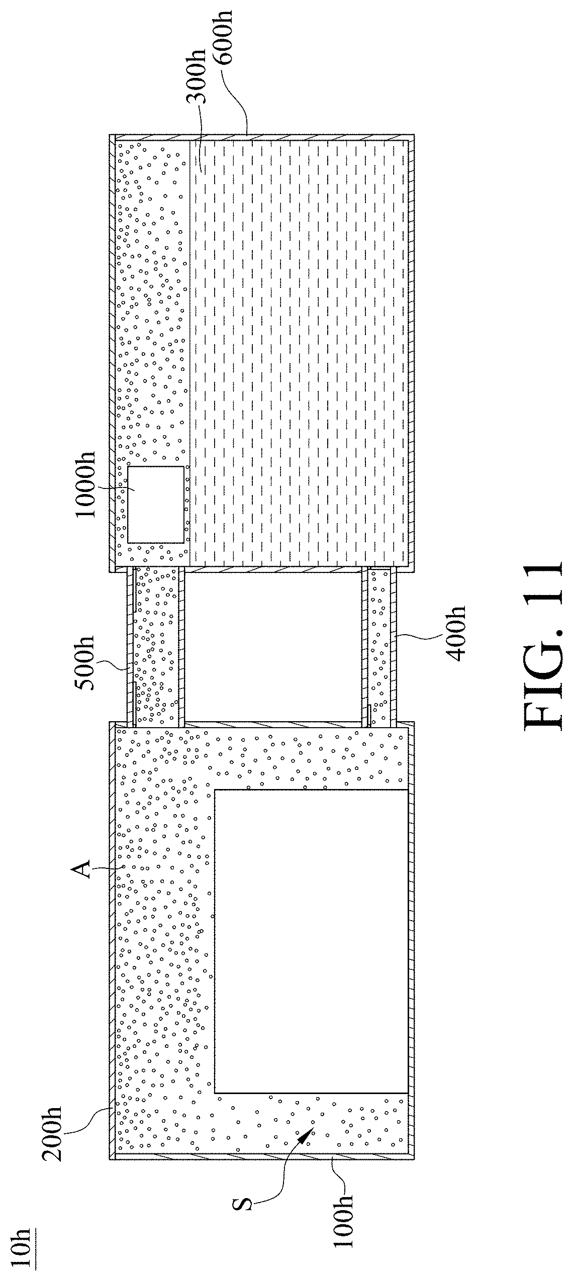
[0016] FIG. 11 is a cross-sectional view of the cooling device and the heat source in FIG. 10 when the operation is completed.
DETAILED DESCRIPTION
[0017] In the following detailed description, for purposes of explanation, numerous specific details are set forth in order to provide a thorough understanding of the disclosed embodiments. It will be apparent, however, that one or more embodiments may be practiced without these specific details. In other instances, well-known structures and devices are schematically shown in order to simplify the drawing.
[0018] Please refer to FIG. 1 to FIG. 2, FIG. 1 is an exploded cross-sectional view of a cooling device and a heat source according to one embodiment of the present disclosure, and FIG. 2 is a cross-sectional view of the cooling device when the heat source is disposed in the cooling device.
[0019] This embodiment provides a cooling device 10a (e.g., an immersion cooling device) configured to cool a heat source 20 (e.g., a server). The cooling device 10a includes a tank 100a, a cover 200a and a cooling liquid 300a. The tank 100a includes a bottom surface 110a, a tank inlet 120a and a tank outlet 130a. As shown in the figure, the tank 100a may be placed on a platform P (e.g., a table) in a way that the bottom surface 110a of the tank 100a faces the platform P. The cover 200a is disposed on the tank 100a. In this embodiment and some embodiments of the present disclosure, the cover 200a and the bottom surface 110a are respectively located at two opposite sides of the tank 100a, but the disclosure is not limited thereto. In some other embodiments, the cover and the bottom surface may be located adjacent to each other. In this embodiment, the cover 200a and the tank 100a form a space S therebetween. The space S is configured to accommodate the heat source 20. The cooling liquid 300a is located in the space S. In this embodiment and some embodiments of the present disclosure, a liquid level 310a of the cooling liquid 300a is located farther away from the bottom surface 110a of the tank 100a than the heat source 20, and the heat source 20 is completely immersed in the cooling liquid 300a, but the disclosure is not limited thereto. In some other embodiments, as long as heat generated by the heat source is able to be transferred to the cooling liquid, the heat source may be partially immersed in the cooling liquid. In this embodiment and some embodiments of the present disclosure, the cooling liquid 300a is volatile, non-conductive and low boiling liquid, such as refrigerant, but the disclosure is not limited thereto. In some other embodiments, the cooling liquid may be pure water or liquid fluoride. In this embodiment, when a signal of a wire of the heat source 20 contacting the cooling liquid 300a is 1 kHz, a permittivity of the cooling liquid 300a is close to 1. In this embodiment and some embodiments of the present disclosure, the permittivity of the cooling liquid 300a is approximately 1.8. In this embodiment, when the heat source 20 and the cooling liquid 300a are both accommodated in the space S, heat generated by the heat source 20 is absorbed by the cooling liquid 300a so as to cause the cooling liquid 300a to evaporate into vapor form (e.g., vapor 320a shown in FIG. 2), and the vapor 320a may be discharged out of the space S via the tank outlet 130a, thereby dissipating the heat. Therefore, there would not be too much vapor 320a remaining in the space S, such that less of the vapor 320a would escape from the opening for receiving the cover 200a when the cover is removed.
[0020] In this embodiment and some embodiments of the present disclosure, the cooling device 10a further includes a liquid channel 400a and a vapor channel 500a, the liquid channel 400a is connected to the tank inlet 120a, and the vapor channel 500a is connected to the tank outlet 130a. The cooling liquid 300a may be poured into the liquid channel 400a to flow into the space S and to replenish the evaporated cooling liquid 300a. The vapor 320a may flow into the vapor channel 500a via the tank outlet 130a. The vapor 320a has a lower density than that of the cooling liquid 300a, a volume flow rate of the vapor 320a is higher than that of the cooling liquid 300a; therefore, to reach a balance of mass flow rate between the tank inlet 120a and the tank outlet 130a, an inner diameter of the vapor channel 500a may be larger than an inner diameter of the liquid channel 400a, but the disclosure is not limited thereto. In some other embodiments, the balance may also be reached by increasing the quantity of the vapor channel.
[0021] Please refer to FIG. 3, which is a cross-sectional view of the cooling device during the operation of the heat source in FIG. 1. During the operation of the heat source 20, a part of the cooling liquid 300a was evaporated into vapor form (i.e., vapor 320a), and then the liquid level 310a of the cooling liquid 300a is fallen to a liquid level 310a'. The vapor 320a leaves the space S from the tank outlet 130a, and the cooling liquid 300a flows into the space S via the tank inlet 120 to replenish the evaporated cooling liquid 300a. Generally, liquid tends to flow down and gas tends to go up, thus, in this embodiment and some embodiments of the present disclosure, the tank inlet 120a of the tank 100a is located closer to the bottom surface 110a of the tank 100a than the tank outlet 130a, but the disclosure is not limited thereto. In some other embodiments, the tank inlet and the tank outlet may be located at the same level.
[0022] In this embodiment and some embodiments of the present disclosure, the vapor channel 500a includes an inlet end 510a and an outlet end 520a. The inlet end 510a is connected to the tank outlet 130a of the tank 100a, and a distance Dla between the inlet end 510a and the bottom surface 110a is substantially equal to a distance D2a between the outlet end 520a and the bottom surface 110a. In other words, the inlet end 510a and the outlet end 520a are substantially located at the same level, but the disclosure is not limited thereto. Please refer to FIG. 4, which is a cross-sectional view of a cooling device according to another embodiment of the present disclosure during the operation of the heat source. This embodiment provides a cooling device 10b, which is similar to the aforementioned cooling device 10a, thus a detailed description of the similar features between these embodiments may not be repeated. In this embodiment and some embodiments of the present disclosure, a distance Dlb of an inlet end 510b and a bottom surface 110b of the cooling device 10b is smaller than a distance D2b of an outlet end 520b and the bottom surface 110b of the cooling device 10b. In other words, a vapor channel 500b is disposed to a tank 100b in an inclined manner. Accordingly, a liquid level 310b of a cooling liquid 300b is allowed to be closer to a cover 200b and the cooling liquid 300b is allowed flows into the inlet end 510b and occupy a portion of the vapor channel 500b, ensuring only the vapor form of the cooling liquid 300b (i.e., vapor 320b) to pass through the outlet end 520b of the vapor channel 500b.
[0023] In the previous embodiment, the cover 200a is placed horizontally, but the disclosure is not limited thereto. Please refer to FIG. 5, which is a cross-sectional view of a cooling device according to yet another embodiment of the present disclosure during the operation of the heat source. This embodiment provides a cooling device 10c, which is similar to the aforementioned cooling device 10a, thus a detailed description of the similar features between these embodiments may not be repeated. In this embodiment and some embodiments of the present disclosure, a cover 200c of the cooling device 10c includes a first side 210c and a second side 220c, a distance D3 between the first side 210c and a bottom surface 110c is larger than a distance D4 between the second side 220c and the bottom surface 110c. In other words, the first side 210c is located farther away from the bottom surface 110c of the tank 100c than the second side 220c. In addition, the first side 210c is closer to a tank outlet 130c of a tank 100c than the second side 220c, such that the vapor form of the cooling liquid 300c (i.e., vapor 320c) tends to flow toward the first side 210c. Consequently, the vapor 320c would easily leave the space S via the tank outlet 130c.
[0024] Please refer to FIG. 6, which is a cross-sectional view of a cooling device according to still another embodiment of the present disclosure during the operation of the heat source. This embodiment provides a cooling device 10d, which is similar to the aforementioned cooling device 10a, thus a detailed description of the similar features between these embodiments may not be repeated. In this embodiment and some embodiments of the present disclosure, the cooling device 10d further includes a heat exchange portion 600d. The heat exchange portion 600d is, for example, a tube, but the disclosure is not limited thereto. In some other embodiments, the heat exchange portion may be another tank. In this embodiment and some embodiments of the present disclosure, the heat exchange portion 600d includes a first end 610d and a second end 620d. The first end 610d is connected to a vapor channel 500d and the second end 620d is connected to a liquid channel 400d. The vapor 320d flows to the first end 610d of the heat exchange portion 600d from the vapor channel 500d. The heat exchange portion 600d is configured to provide an extra space for the processes of condensation and evaporation of a cooling liquid 300d to occur (i.e., the transition from the cooling liquid 300d and vapor 320d). The vapor 320d turns into the cooling liquid 300d in the heat exchange portion 600d and flows back to the liquid channel 400d through the second end 620d due to gravity. In short, the cooling liquid 300d in the space S is able to be evaporated into the gaseous phase and then is condensed to flow back to the space S, forming a circulation without losing any of it.
[0025] Please refer to FIG. 7, which is a cross-sectional view of a cooling device according to still yet another embodiment of the present disclosure during the operation of the heat source. This embodiment provides a cooling device 10e, which is similar to the aforementioned cooling device 10a, thus a detailed description of the similar features between these embodiments may not be repeated. In this embodiment and some embodiments of the present disclosure, the cooling device 10e further includes a heat dissipation device 700e. The heat dissipation device 700e is, for example, a liquid cooling device and is connected to a heat exchange portion 600e. The heat dissipation device 700e is able to absorb and then dissipate heat in the vapor 320e in the heat exchange portion 600e. Therefore, the heat dissipation device 700e is able to accelerate the phase transition of the cooling liquid 300e. In some other embodiments, the heat dissipation device may be a fan that is not in contact with the heat exchange portion; in such a case, the airflow generated by the fan also helps to accelerate the phase transition of the cooling liquid.
[0026] Please refer to FIG. 8, which is a cross-sectional view of a cooling device according to still yet another embodiment of the present disclosure during the operation of the heat source. This embodiment provides a cooling device 10f, which is similar to the aforementioned cooling device 10a, thus a detailed description of the similar features between these embodiments may not be repeated. In this embodiment and some embodiments of the present disclosure, the cooling device 10f further includes an electrical connector 800f disposed at a cover 200f. In addition, the electrical connector 800f is located in a hole (not shown in the figures) of the cover 200f and is electrically connected to the heat source 20 via a wire 22 located in the tank 100f. The electrical connector 800f is configured to transmit electricity or signal to the heat source 20 or receive electricity or signal from the heat source 20. This allows the heat source 20 to exchange electrical power or signal to another external device through the wire 22 and the electrical connector 800f. In addition, the hole of the cover 200 may be, for example, in a square shape, and the electrical connector 800f is easier to be sealed to the cover 200f with respect to the conventional gap between the wire and the tank. As a result, the air-tightness of the tank 100f is increased with respect to the conventional tank.
[0027] Please refer to FIG. 9, which is a cross-sectional view of a cooling device according to still yet another embodiment of the present disclosure during the operation of the heat source. This embodiment provides a cooling device 10g, which is similar to the aforementioned cooling device 10a, thus a detailed description of the similar features between these embodiments may not be repeated. In this embodiment and some embodiments of the present disclosure, the cooling device 10g further includes a liquid pump device 900g, and a heat exchange portion 600g is a tank. The liquid pump device 900g is connected to and disposed on a liquid channel 400g and is connected to a tank 100g and the heat exchange portion 600g via the liquid channel 400g. In this embodiment and some embodiments of the present disclosure, a cooling liquid 300g in the space S can be completely pumped to the heat exchange portion 600g by the liquid pump device 900g. By doing so, the vapor form of the cooling liquid 300g is prevented from escaping from the opening for receiving a cover 200g when the cover 200g is removed. Further, there may be a valve (not shown in the figures) disposed in the liquid pump device 900g for preventing the cooling liquid 300g from flowing back to the space S. During the operating of the heat source 20, the valve is switched on. However, the valve is optional, and the disclosure is not limited thereto.
[0028] Please refer to FIG. 10 and FIG. 11, FIG. 10 is a cross-sectional view of a cooling device according to still yet another embodiment of the present disclosure during the operation of the heat source, and FIG. 11 is a cross-sectional view of the cooling device and the heat source in FIG. 10 when the operation is completed. This embodiment provides a cooling device 10h, which is similar to the aforementioned cooling device 10a, thus a detailed description of the similar features between these embodiments may not be repeated. In this embodiment and some embodiments of the present disclosure, the cooling device 10h further includes an air pump device 1000h located in a heat exchange portion 600h which is connected to a tank 100g via a vapor channel 500h. In this embodiment and some embodiments of the present disclosure, the space S may be filled with air A with the help of the air pump device 1000h so as to force a cooling liquid 300h and a vapor 320h to move toward the heat exchange portion 600h. By doing so, most in the space S is the air A and vapor form of the cooling liquid 300h is prevented from escaping from the opening for receiving a cover 200h when the cover 200h is removed. Further, there may be a valve (not shown in the figures) disposed in the air pump device 1000h for preventing the air A from flowing back to the heat exchange portion 600h. During the operating of the heat source 20, the valve is switched on. However, the valve is optional, and the disclosure is not limited thereto.
[0029] According to the cooling device in the embodiments abovementioned, when the heat source and the cooling liquid are both accommodated in the space, heat generated by the heat source is absorbed by the cooling liquid so as to cause the cooling liquid to evaporate into vapor form, and the vapor may be discharged out of the space via the tank outlet, thereby dissipating the heat. Therefore, there would not be too much vapor remaining in the space, such that less of the vapor would escape from the opening for receiving the cover when the cover is removed.
[0030] In some embodiments, the cooling device further includes a liquid channel and a vapor channel, the liquid channel is connected to the tank inlet, and the vapor channel is connected to the tank outlet. To reach a balance of mass flow rate between the tank inlet and the tank outlet, an inner diameter of the vapor channel may be larger than an inner diameter of the liquid channel.
[0031] In some embodiments, the tank inlet of the tank is located closer to the bottom surface of the tank than the tank outlet. Generally, liquid tends to flow down and gas tends to go up.
[0032] In some embodiments, the vapor channel is disposed to the tank in an inclined manner. Accordingly, the liquid level of the cooling liquid is allowed to be closer to the cover and the cooling liquid is allowed flows into the inlet end and occupy a portion of the vapor channel, ensuring only the vapor form of the cooling liquid to pass through the outlet end of the vapor channel.
[0033] In some embodiments, the first side is located farther away from the bottom surface than the second side. In addition, the first side is closer to the tank outlet than the second side, such that the vapor form of the cooling liquid tends to flow toward the first side. Consequently, the vapor would easily leave the space via the tank outlet.
[0034] In some embodiments, the cooling device further includes a heat exchange portion. The heat exchange portion is configured to provide an extra space for the processes of condensation and evaporation of the cooling liquid to occur (i.e., the transition from the cooling liquid and vapor). The vapor turns into the cooling liquid in the heat exchange portion and flows back to the liquid channel through the second end due to gravity. In short, the cooling liquid in the space is able to be evaporated into the gaseous phase and then is condensed to flow back to the space, forming a circulation without losing any of it.
[0035] In some embodiments, the cooling device further includes a heat dissipation device. The heat dissipation device is able to absorb and then dissipate heat in the vapor in the heat exchange portion. Therefore, the heat dissipation device is able to accelerate the phase transition of the cooling liquid.
[0036] In some embodiments, the cooling device further includes an electrical connector disposed at the cover. In addition, the electrical connector is located in a hole of the cover and is electrically connected to the heat source via a wire located in the tank. The electrical connector is configured to transmit electricity or signal to the heat source or receive electricity or signal from the heat source. This allows the heat source to exchange electrical power or signal to another external device through the wire and the electrical connector. In addition, the hole of the cover may be, for example, in a square shape, and the electrical connector is easier to be sealed to the cover with respect to the conventional gap between the wire and the tank. As a result, the air-tightness of the tank is increased with respect to the conventional tank.
[0037] In some embodiments, the cooling device further includes a liquid pump device, and the heat exchange portion is a tank. The cooling liquid in the space can be completely pumped to the heat exchange portion by the liquid pump device. By doing so, the vapor form of the cooling liquid is prevented from escaping from the opening for receiving the cover when the cover is removed.
[0038] In some embodiments, the cooling device further includes an air pump device. The space may be filled with air with the help of the air pump device so as to force the cooling liquid and the vapor to move toward the heat exchange portion. By doing so, most in the space is the air and vapor form of the cooling liquid is prevented from escaping from the opening for receiving the cover when the cover is removed.
[0039] The embodiments are chosen and described in order to best explain the principles of the present disclosure and its practical applications, to thereby enable others skilled in the art best utilize the present disclosure and various embodiments with various modifications as are suited to the particular use being contemplated. It is intended that the scope of the present disclosure is defined by the following claims and their equivalents.
* * * * *
D00000
D00001
D00002
D00003
D00004
D00005
D00006
D00007
D00008
XML
uspto.report is an independent third-party trademark research tool that is not affiliated, endorsed, or sponsored by the United States Patent and Trademark Office (USPTO) or any other governmental organization. The information provided by uspto.report is based on publicly available data at the time of writing and is intended for informational purposes only.
While we strive to provide accurate and up-to-date information, we do not guarantee the accuracy, completeness, reliability, or suitability of the information displayed on this site. The use of this site is at your own risk. Any reliance you place on such information is therefore strictly at your own risk.
All official trademark data, including owner information, should be verified by visiting the official USPTO website at www.uspto.gov. This site is not intended to replace professional legal advice and should not be used as a substitute for consulting with a legal professional who is knowledgeable about trademark law.