Noise Reducing Cable Splitter
Ficyk; Eugene John
U.S. patent application number 16/172409 was filed with the patent office on 2020-04-30 for noise reducing cable splitter. The applicant listed for this patent is Leggett & Platt Canada Co.. Invention is credited to Eugene John Ficyk.
| Application Number | 20200132108 16/172409 |
| Document ID | / |
| Family ID | 70326199 |
| Filed Date | 2020-04-30 |


| United States Patent Application | 20200132108 |
| Kind Code | A1 |
| Ficyk; Eugene John | April 30, 2020 |
NOISE REDUCING CABLE SPLITTER
Abstract
A latching system includes a first lever connected to a first cable having a first cable end, a second lever connected to a second cable having a second cable end, a latch connected to a third cable having a third cable end, and a cable splitter assembly. The cable splitter assembly has a housing with a first end and a second end and a body with an interior surface defining an interior chamber. A carriage is configured to translate within the interior chamber. The carriage includes a carriage body with a plurality of cavities arranged to seat the respective first, second, and third cable ends and a plurality of resilient arms integrally formed as one piece with the carriage body.
| Inventors: | Ficyk; Eugene John; (Livonia, MI) | ||||||||||
| Applicant: |
|
||||||||||
|---|---|---|---|---|---|---|---|---|---|---|---|
| Family ID: | 70326199 | ||||||||||
| Appl. No.: | 16/172409 | ||||||||||
| Filed: | October 26, 2018 |
| Current U.S. Class: | 1/1 |
| Current CPC Class: | E05B 77/36 20130101; E05B 85/12 20130101; F16C 1/101 20130101; E05B 79/20 20130101; F16C 1/108 20130101; F16C 1/262 20130101; F16C 1/106 20130101 |
| International Class: | F16C 1/10 20060101 F16C001/10; E05B 79/20 20060101 E05B079/20 |
Claims
1. A latching system comprising: a first lever connected to a first cable having a first cable end; a second lever connected to a second cable having a second cable end; a latch connected to a third cable having a third cable end; and a cable splitter assembly, the assembly including a housing having a first end and a second end and a body with an interior surface defining an interior chamber; a carriage configured to translate within the interior chamber, the carriage having a carriage body with a plurality of cavities arranged to seat the respective first, second, and third cable ends and a plurality of resilient arms integrally formed as one piece with the carriage body.
2. The latching system of claim 1, wherein the carriage body includes a first side and an opposing second side, and wherein the plurality of resilient arms are integrally formed as part of the first side.
3. The latching system of claim 2, wherein each resilient arm of the plurality of resilient arms includes a contact surface disposed between the respective resilient arm and the interior surface.
4. The latching system of claim 2, wherein each resilient arm of the plurality of resilient arms includes a contact member extending away from the first side.
5. The latching system of claim 1, wherein the carriage further includes a first end and an opposing second end, wherein the carriage body further includes a plurality of channels, each channel in communication with one cavity of the plurality of cavities.
6. The latching system of claim 5, wherein each cavity is formed at one of the first end or the second end, and wherein an associated channel extends from the other of the first end or second end to the cavity.
7. The latching system of claim 1, further including a first terminal at the first cable end; a second terminal at the second cable end; and a third terminal at the third cable end, wherein each of the first, second, and third terminals is configured to sit within a respective cavity of the plurality of cavities and includes a vibration-reducing component.
8. The latching system of claim 7, wherein each vibration-reducing component is in the form of a ring positioned at least partially around a portion of each respective terminal.
9. The latching system of claim 8, wherein each ring is formed of an elastomeric material.
10. A carriage for a cable splitter assembly, the assembly including a housing containing an interior chamber, the carriage configured to translate within the interior chamber and comprising a carriage body with a plurality of recesses, each recess arranged to seat a cable terminal end and forming, in conjunction with the carriage body, a resilient arm.
11. The carriage of claim 10, wherein the carriage further includes a first end and an opposing second end, wherein the carriage body further includes a plurality of channels, each channel in communication with one recess of the plurality of recesses.
12. The carriage of claim 11, wherein each recess is formed at one of the first end or the second end, and wherein an associated channel extends from the other of the first end or second end to the recess.
13. The carriage of claim 10, wherein each arm is biased away from the one side.
14. The carriage of claim 10, wherein each arm is formed to at least partially extend away from the carriage body.
15. A cable splitter subassembly comprising: a housing having a first end and a second end and a body with an interior surface defining a bounded interior chamber; and a carriage configured to translate within the bounded interior chamber, the carriage having a carriage body with a plurality of cavities, each cavity arranged to seat a cable terminal end, and a plurality of resilient arms extending from the carriage body, each arm including a contact surface configured to contact a portion of the interior chamber during translation of the carriage within the housing.
16. The cable splitter subassembly of claim 15, wherein the second end includes an opening, the subassembly further including a cap configured to cover the opening, wherein the cap includes a plurality of cap channels extending therethrough such that in an assembled state of the cap with the housing the bounded interior chamber is in communication with an environment external to the housing.
17. The cable splitter subassembly of claim 16, wherein the carriage further includes a first end and an opposing second end, wherein the carriage body further includes a plurality of channels, each channel in communication with a cavity of the plurality of cavities.
18. The cable splitter subassembly of claim 15, wherein each contact surface is a portion of a contact member formed at the end of each arm.
Description
BACKGROUND
[0001] The present disclosure relates to a multi-cable splitter assembly, such as those used in connection with interior automotive cables.
[0002] Many automotive systems such as door and seat latches use cable splitters to efficiently function. Multi-cable splitter assemblies, however, tend to have components that slide or are otherwise loose within the assembly casing, and in current assemblies this produces objectionable noise like buzz, squeak, and rattle (BSR).
SUMMARY
[0003] A latching system includes a first lever connected to a first cable having a first cable end, a second lever connected to a second cable having a second cable end, a latch connected to a third cable having a third cable end, and a cable splitter assembly. The cable splitter assembly has a housing with a first end and a second end and a body with an interior surface defining an interior chamber. A carriage is configured to translate within the interior chamber. The carriage includes a carriage body with a plurality of cavities arranged to seat the respective first, second, and third cable ends and a plurality of resilient arms integrally formed as one piece with the carriage body.
[0004] A carriage for a cable splitter assembly, in which the assembly includes a housing containing an interior chamber and the carriage is configured to translate within the interior chamber, includes a carriage body with a plurality of recesses. Each recess is arranged to seat a cable terminal end and forms, in conjunction with the carriage body, a resilient arm.
[0005] A cable splitter subassembly includes a housing having a first end and a second end and a body with an interior surface defining a bounded interior chamber. A carriage is configured to translate within the bounded interior chamber and has a carriage body with a plurality of cavities. Each cavity is arranged to seat a cable terminal end and a plurality of resilient arms extend from the carriage body. Each arm includes a contact surface configured to contact a portion of the interior chamber during translation of the carriage within the housing.
BRIEF DESCRIPTION OF THE DRAWINGS
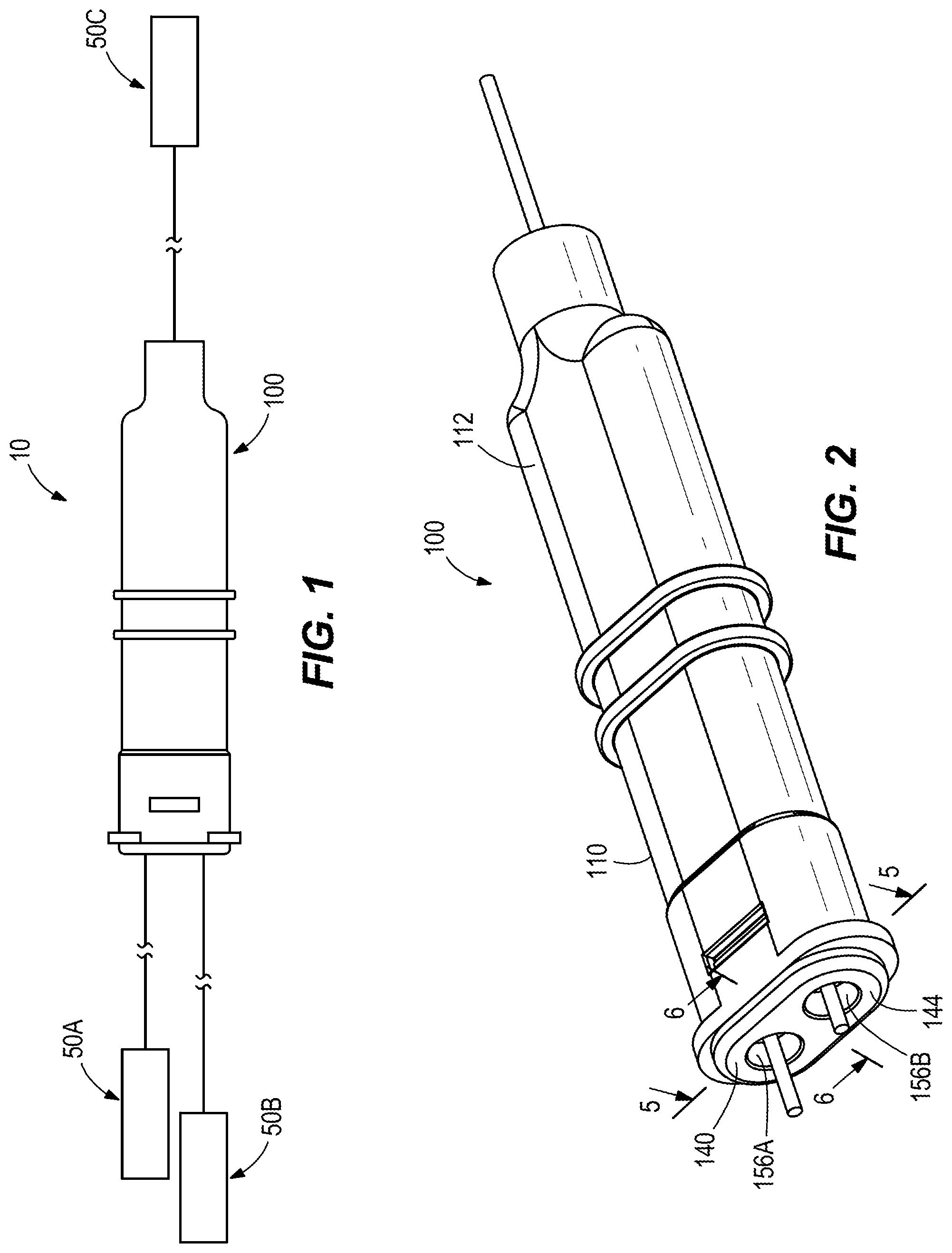
[0006] FIG. 1 is a view of a lever system including a cable splitter assembly.
[0007] FIG. 2 is a perspective view of the cable splitter assembly of FIG. 1.
[0008] FIG. 3 is a perspective view of the interior of the cable splitter assembly of FIG. 1.
[0009] FIG. 4 is an exploded view of the cable splitter assembly of FIG. 1.
[0010] FIG. 5 is a cross-sectional view of the cable splitter taken along line 5-5 of FIG. 2.
[0011] FIG. 6 is a cross-sectional view of the cable splitter taken along line 6-6 of FIG. 2.
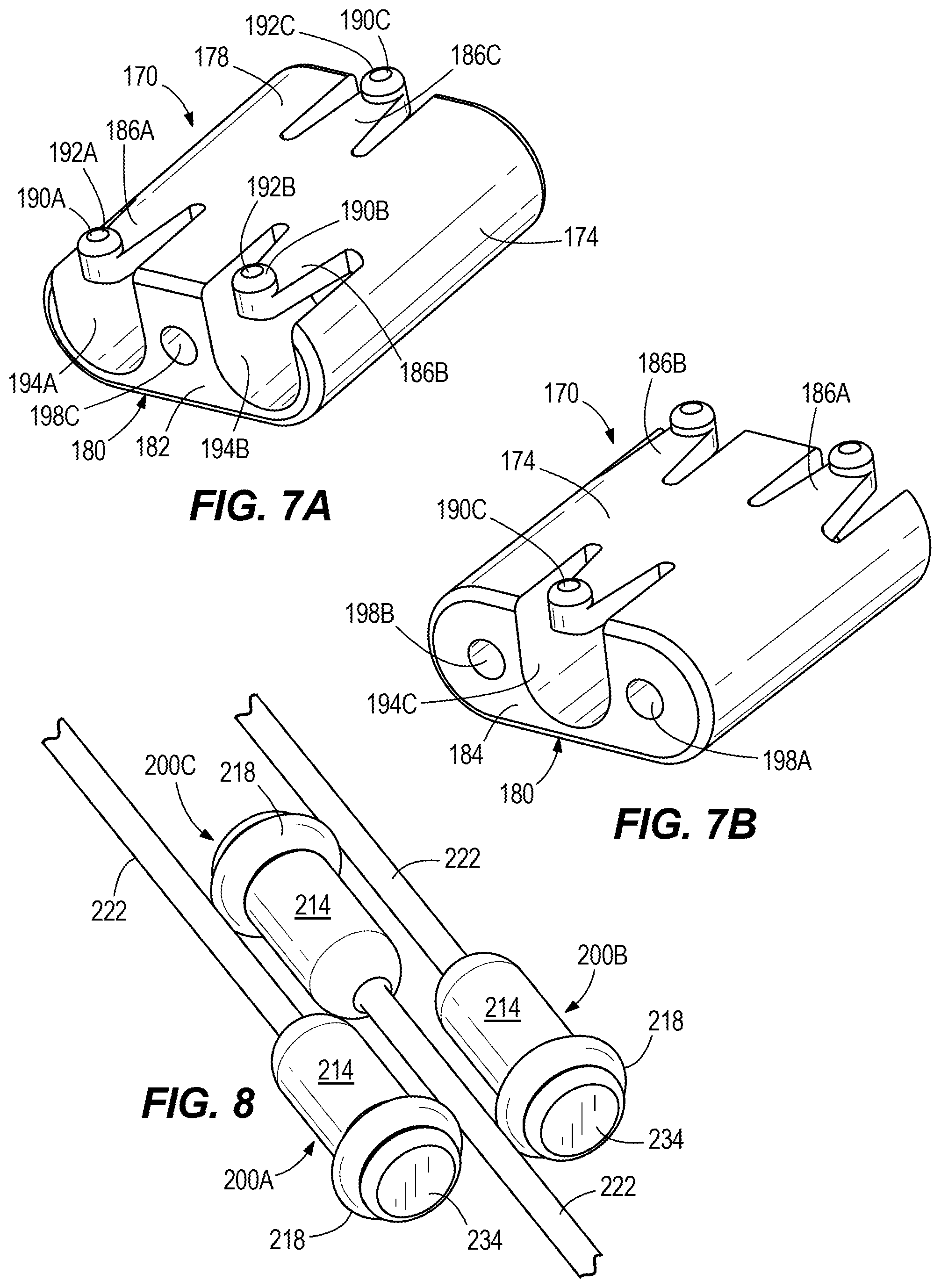
[0012] FIGS. 7A and 7B are perspective views of a carriage member of the cable splitter assembly of FIG. 1.
[0013] FIG. 8 is a perspective view of a cable sub assembly of the cable splitter assembly of FIG. 1.
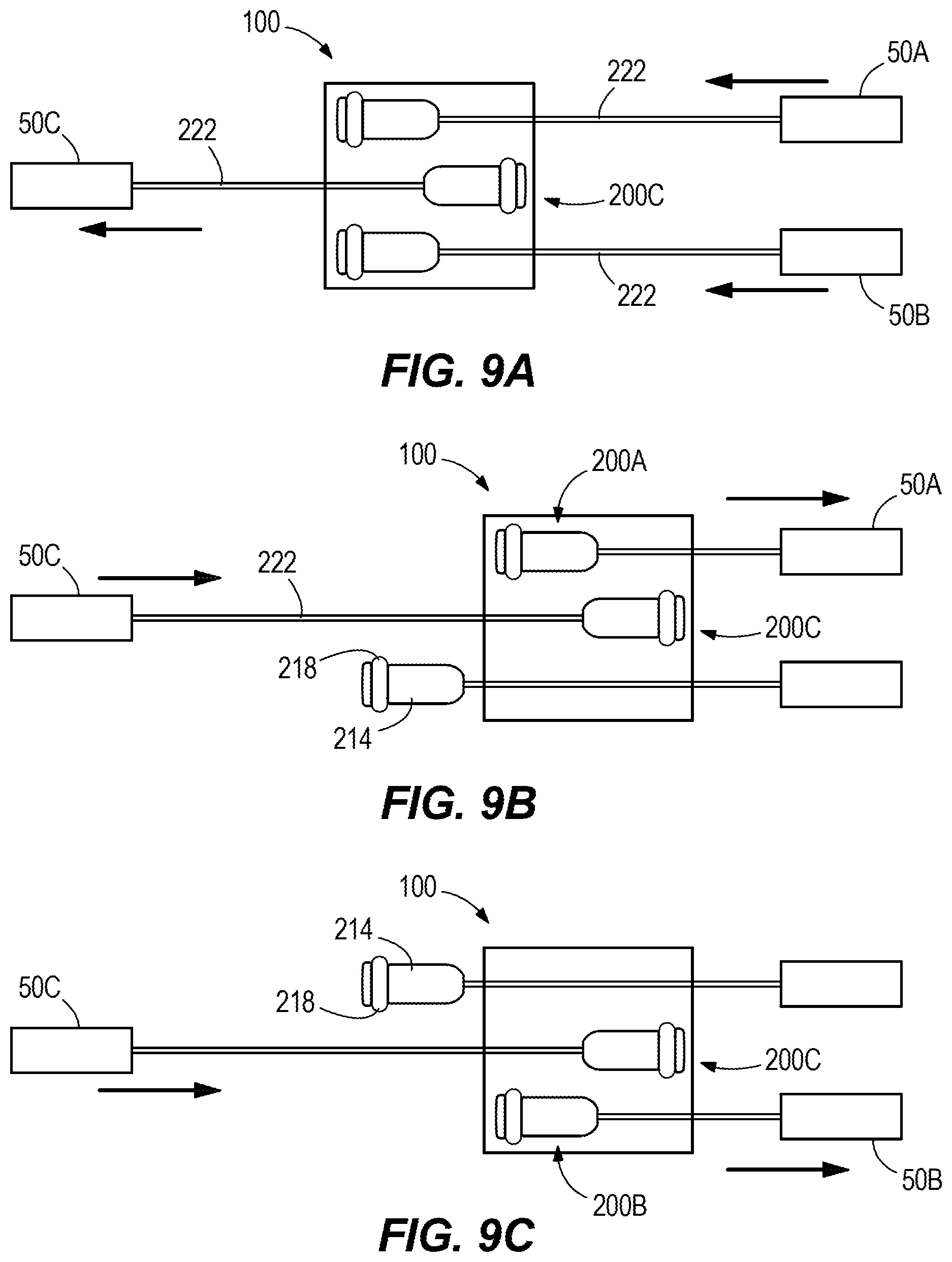
[0014] FIGS. 9A-9C are schematic diagrams of the cable splitter assembly of FIG. 1 in use.
DETAILED DESCRIPTION
[0015] Before any embodiments of the disclosure are explained in detail, it is to be understood that the disclosure is not limited in its application to the details of construction and the arrangement of components set forth in the following description or illustrated in the following drawings. The disclosure is capable of supporting other embodiments and of being practiced or of being carried out in various ways. Also, it is to be understood that the phraseology and terminology used herein is for the purpose of description and should not be regarded as limiting.
[0016] FIG. 1 depicts a lever/latch cable system 10 comprising a plurality (three illustrated) of tensioning devices 50A-50C connected by a cable splitter assembly 100. The devices can be a combination of levers, latches, or other tension driven devices as the application demands. Referring also to FIGS. 2-4, the cable splitter assembly 100 includes a housing 110, a cap 140, a carriage or carrier 170, and three cable assemblies 200A-200C.
[0017] The housing 110 includes a housing body 112 generally elongated in shape from a first open end 114 to a second open end 118. In particular, the body 112 "necks" down near the second open end 118 such that the second open end 118 is a generally cylindrical portion of the body 112 having a lesser width than the remainder of the body 112 in at least one direction. The body 112 has an interior surface 122, which defines an interior chamber 126 therein and includes a stop surface 130 (FIG. 5) adjacent the second open end 118. A pair of apertures 134A, 134B adjacent the first open end 114 extend through the body 112 to the interior chamber 126.
[0018] With continued reference to FIGS. 2-4, the cap 140 includes a first end 144, a second end 148, an exterior surface 152, and a pair of channels 156A, 156B therethrough from the first end 144 to the second end 148. The first end 144 is sized to cover the opening of the first open end 114. The exterior surface 152 presents an opposing pair of protrusions 168A, 168B.
[0019] The carriage 170, further illustrated in FIGS. 7A and 7B, includes a body 174, a first side 178, a second side 180, a first end 182, and a second end 184. Integrally formed as one piece with the body 174 and with the first side 178 are resilient or flexible tabs or arms 186A-186C, each with a knob or contact member 190A-190C, respectively, projecting away from the first side 178 and with a contact surface 192A-192C. Alternatively, the body 174 can be described as including resilient or flexible arms 186A-186C extending therefrom and having contact members 190A-190C. Yet alternatively, the body 174 includes cavities or recesses 194A-194C that thereby form resilient arms 186A-186C of the body 174. In some embodiments, each arm 186A, 186B, 186C is biased directionally away from the body 174. In some embodiments, each arm 186A, 186B, 186C is formed to at least partially extend away from the body 174.
[0020] The carriage 170 further includes a first channel 198A extending from the first cavity 194A to the second end 184, a second channel 198B extending from the second cavity 194B to the second end 184, and a third channel 198C extending from the third cavity 194C to the first end 182. In other words, channels 198A-198C in combination with associated cavities 194A-194C extend effectively through the body 174 from the first end 182 to the second end 184.
[0021] FIG. 8 shows the three cable assemblies 200A-200C. Each cable assembly includes a terminal end or terminal 214, a vibration or noise reducing component or bumper or ring 218, and a cable 222. The terminal includes a groove or channel 230 near or adjacent a terminal end 234 of each terminal 214. The bumper 218 is an annular member or toroidal member made of elastomeric or other relatively soft or resilient material and configured to at least partially fit within an associated groove 230 of a terminal 214. In other embodiments, the bumper 218 may be a rubber or elastomeric cap, an over molded cap, or a collar-like structure about a portion of the terminal 214. The terminal ends 234 are sized such that they cannot slide within a channel 198.
[0022] In assembly, the cable 222 of assembly 200C passes through open end 118 of the housing 110, through the housing 110, and through channel 198C of the carriage 170, at which point it is joined or coupled to the associated terminal 214 in a conventional manner. The cables 222 of assemblies 200A and 200B likewise pass through channels 156A, 156B, respectively, of the cap 140 and thereafter through channels 198A, 198B, respectively, of the carriage 170, at which point they are joined to respective terminals 214. Bumpers 218 can be assemble onto terminals 214 beforehand or afterward. The assemblies 200A-200C and carriage 170 are positioned within the chamber 126 and the cap 140 inserted into the first open end 114. Specifically, the cap 140 is configured to cover the opening of the first open end 114. The exterior surface 152 of the cap 140 contacts the interior surface 122 of the housing 110, and the cap 140 is aligned so that each protrusion 168A, 168B on the exterior surface 152 is received by an aperture 134A, 134B of the housing 110, securing the cap 140 in place. In this embodiment, the cap 140 is removably coupled to the housing 110 via a snapping mechanism. In other embodiments, the cap 140 may be press fit to the housing 110, or hinged, or clasped, or otherwise removably coupled to the housing 110.
[0023] Once assembled, the carriage 170 is confined between the stop surface 130 and the second end 148 of the cap 140. The cables 222 may be previously connected to the respective tensioning devices 50A-50C or may be connected at any time during or after assembly of the splitter assembly 100.
[0024] In operation, the carriage 170 is configured to slide within the interior chamber 126 between the stop surface 130 and the second end 148 of the cap 140 dependent on forces applied to the cables 222.
[0025] Specifically, referring to FIG. 9A, tensioning device 50C is a lever and tensioning devices 50A and 50B are latches. In this arrangement, pulling lever 50C results in cable assembly 200C pulling splitter assembly 100 leftward (in this reference frame), thereby pulling both of latches 50A, 50B. As carriage 170 translates within interior chamber 126, the contact surfaces 192A-192C of flexible tabs or arms 186A-186C, which are each disposed between a respective arm and the interior surface 122, lightly contact a portion of interior surface 122 to limit or impede non-translatory movement of the carriage 170 within the housing 110, i.e., hindering any non-linear or non-translatory movement (movement not aligned with the direction of tension of cable assembly 200C) or impact between surfaces of the carriage 170 and the interior surface 122. The flexible arms 186A-186C therefore operate to minimize or eliminate clearance between the carriage 170 and the interior surface 122.
[0026] Referring to FIGS. 9B-9C, tensioning devices 50A and 50B are levers and tensioning device 50C is a latch. As shown in FIG. 9B, pulling lever 50A rightward causes cable assembly 200A to pull carriage 170 rightward, which brings with it cable assembly 200C and latch 50C. The flexible tabs or arms 186A-186C cooperate with the interior surface 122 as previously described. Moreover, cable assembly 200B, and more precisely associated terminal 214, releases or slides from its seated position within the carriage 170 (essentially remaining in place) and may thereby be loose within the interior chamber 126. Bumper 218, which protrudes from the normal contour of the terminal 214, reduces the noise or vibration associated with any contact between the terminal 214 and the interior surface 122. Pulling lever 50B (FIG. 9C) results in the same effect between the terminal 214 of cable assembly 200A and the interior surface 122.
[0027] In the illustrated embodiment, the cable splitter assembly 100 contains a total of three cable assemblies 200A-200C arranged in a two to one conversion structure. In other embodiments, however, the cable splitter assembly 100 may contain just two cables with a one to one structure, or any other number of cables in a similar conversion structure (for example, six cables, with two on one side and four on the other, three on one side and three on the other, one on one side and five on the other, etc. with all other parts scaled and adapted accordingly, i.e., a carriage with a sufficient number of cavities and resilient arms as previously described.
[0028] Various features of the disclosure are set forth in the following claims.
* * * * *
D00000
D00001
D00002
D00003
D00004
D00005
XML
uspto.report is an independent third-party trademark research tool that is not affiliated, endorsed, or sponsored by the United States Patent and Trademark Office (USPTO) or any other governmental organization. The information provided by uspto.report is based on publicly available data at the time of writing and is intended for informational purposes only.
While we strive to provide accurate and up-to-date information, we do not guarantee the accuracy, completeness, reliability, or suitability of the information displayed on this site. The use of this site is at your own risk. Any reliance you place on such information is therefore strictly at your own risk.
All official trademark data, including owner information, should be verified by visiting the official USPTO website at www.uspto.gov. This site is not intended to replace professional legal advice and should not be used as a substitute for consulting with a legal professional who is knowledgeable about trademark law.