Screw Spindle Pump, Fuel Pump Assembly, and Fuel Pump Unit
DEICHMANN; Johannes ; et al.
U.S. patent application number 16/626443 was filed with the patent office on 2020-04-30 for screw spindle pump, fuel pump assembly, and fuel pump unit. The applicant listed for this patent is CPT GROUP GMBH. Invention is credited to Johannes DEICHMANN, Tim GONNERMANN, Marc VOLKER.
| Application Number | 20200132070 16/626443 |
| Document ID | / |
| Family ID | 62712979 |
| Filed Date | 2020-04-30 |


| United States Patent Application | 20200132070 |
| Kind Code | A1 |
| DEICHMANN; Johannes ; et al. | April 30, 2020 |
Screw Spindle Pump, Fuel Pump Assembly, and Fuel Pump Unit
Abstract
A screw-spindle pump comprising: first and second screw spindles forming running and drive spindles, respectively, and a pump housing configured to receive the first and second screw spindles. The first and second screw spindles form, with at least the pump housing, delivery chambers, moving from a suction side to a pressure side of the pump as a consequence due to rotation of the screw spindles. The pump housing has an elongate insert, as an abutment for the first and second screw spindles and against which the first and second screw spindles are supported, the elongate insert having a first portion forming a first abutment for the second screw spindle and a second portion forming a second abutment for the first screw spindle. The elongate insert is clamped into a receptacle of the pump housing using a cross-sectional dimension of the elongate insert.
| Inventors: | DEICHMANN; Johannes; (Rotenburg, DE) ; GONNERMANN; Tim; (Wehretal, DE) ; VOLKER; Marc; (Magdeburg, DE) | ||||||||||
| Applicant: |
|
||||||||||
|---|---|---|---|---|---|---|---|---|---|---|---|
| Family ID: | 62712979 | ||||||||||
| Appl. No.: | 16/626443 | ||||||||||
| Filed: | June 18, 2018 | ||||||||||
| PCT Filed: | June 18, 2018 | ||||||||||
| PCT NO: | PCT/EP2018/066150 | ||||||||||
| 371 Date: | December 24, 2019 |
| Current U.S. Class: | 1/1 |
| Current CPC Class: | F04C 2210/1044 20130101; F01C 21/108 20130101; F04C 2240/30 20130101; F01C 21/02 20130101; F04C 2/082 20130101; F04C 2/165 20130101; F04C 2230/60 20130101; F04C 11/008 20130101; F04C 15/0042 20130101; F04C 2/16 20130101 |
| International Class: | F04C 2/16 20060101 F04C002/16; F04C 11/00 20060101 F04C011/00 |
Foreign Application Data
| Date | Code | Application Number |
|---|---|---|
| Jun 27, 2017 | DE | 10 2017 210771.5 |
Claims
1-15. (canceled)
16. A screw-spindle pump comprising: a first screw spindle (14) and a second screw spindle (16), wherein the second screw spindle (16) is a drive spindle and the first screw spindle (14) is a running spindle that runs oppositely with respect to the second screw spindle (16), and a pump housing (10) configured to receive the first and second screw spindles (14, 16), wherein the first and second screw spindles (14, 16) form, together with at least the pump housing (10), delivery chambers (18), which move from a suction side (20) of the pump to a pressure side (22) of the pump as a consequence of a rotation of the first and second screw spindles (14, 16), wherein the pump housing (10) has an elongate insert (8), as an abutment for the first and second screw spindles (14, 16) and against which the first and second screw spindles (14, 16) are supported, the elongate insert (8) having a first portion forming a first abutment for the second screw spindle (16) and a second portion forming a second abutment for the first screw spindle (14), and wherein the elongate insert (8) is clamped into a corresponding receptacle of the pump housing (10, 12) using a cross-sectional dimension of the elongate insert (8).
17. The pump as claimed in claim 16, wherein the elongate insert (8) has a width cross-sectional dimension and a height cross-sectional dimension, and the cross-sectional dimension of the elongate insert (8) that is clamped is one of the width cross-sectional dimension and the height cross-sectional dimension.
18. The pump as claimed in claim 17, wherein the width cross-sectional dimension is equal to the height cross-sectional dimension.
19. The pump as claimed in claim 18, wherein the pump housing (10) has at least one sectionally formed projection (26a, 26b), as a receptacle, that extends from the pump housing (10) into an inlet opening (6) of the pump housing (10) transverse to a longitudinal direction (X-X) of the pump housing, wherein the elongate insert (8) is clamped at the at least one projection.
20. The pump as claimed in claim 19, wherein the at least one sectionally formed projection comprises a first projection (26a) and a second projection (26b), which together comprise the receptacle, wherein the first and second projections extend into the inlet opening (6) of the pump housing (10), wherein the elongate insert (8) is clamped between the first and second projections (26a, 26b).
21. The pump as claimed in claim 20, wherein the first and second projections (26a, 26b) are arranged orthogonal to the longitudinal direction (X-X) of the pump (4).
22. The pump as claimed in claim 21, further comprising a pump housing section (24) arranged transverse to the longitudinal direction (X-X) of the pump (4) and on which the first and second projections (26a, 26b) are formed.
23. The pump as claimed in claim 22, wherein the pump housing section (24) is arranged orthogonal to the longitudinal direction (X-X) of the pump (4).
24. The pump as claimed in claim 23, wherein the first projection (26a) and the second projection (26b) are arranged on the pump housing (10, 24) so as to diametrically oppose one another.
25. The pump as claimed in claim 16, wherein the elongate insert (8) is cuboidal or prismatic in shape.
26. The pump as claimed in claim 16, wherein the elongate insert (8) is made from one selected from the group of: a ceramic, a metal and a plastic.
27. The pump as claimed in claim 20, wherein the pump housing (10) has a pump cover (12), in which the elongate insert (8) is clamped between the first and second projections (26a, 26b).
28. The pump as claimed in claim 27, wherein the pump housing (10) and/or the pump cover (12) are/is formed as injection moldings/an injection molding.
29. A fuel delivery assembly comprising: an electric motor; and the screw-spindle pump (4) as claimed in claim 16, wherein the electric motor is configured to drive the screw-spindle pump (4).
30. A fuel delivery unit for use in a fuel tank of a vehicle, comprising a fuel delivery assembly as claimed in claim 29, and having a swirl pot in which the fuel delivery assembly is arranged to deliver fuel from the swirl pot to an internal combustion engine.
Description
CROSS REFERENCE TO RELATED APPLICATIONS
[0001] This is a U.S. national stage of International application No. PCT/EP2018/066150, filed on Jun. 18, 2018, which claims priority to German Application No. 10 2017 210 771.5, filed Jun. 27, 2017, the content of each of which is incorporated herein by reference.
BACKGROUND OF THE INVENTION
1. Field of the Invention
[0002] The present invention relates to a screw-spindle pump, to a fuel delivery assembly comprising such a screw-spindle pump and to a fuel delivery unit comprising such a fuel delivery assembly, for use in vehicles, in particular in passenger motor vehicles and/or utility vehicles.
2. Description of the Prior Art
[0003] Screw-spindle pumps--also referred to as screw pumps--are positive displacement pumps whose displacer has the form of a spindle screw. Two oppositely running screw spindles, which are formed with a threaded profiling, engage into one another and displace a delivery medium, which may for example be a fuel--for example gasoline or diesel fuel--for an internal combustion engine of a passenger motor vehicle and/or a utility vehicle. The combination of the spindle screws and a pump housing in which the screw spindles are arranged and guided is also referred to as a pump stage. The two screw spindles form, in combination with the pump housing, delivery chambers for the delivery medium. The delivery chambers travel from a suction side or inlet side to a pressure side or outlet side of the pump or pump stage as a consequence of a rotation of the screw spindles, and thereby transport the sucked-in delivery medium.
[0004] Within the context of the present disclosure, the terms pump and pump stage are to be understood as meaning one and the same object.
[0005] Pumps of this type are used, for example, in fuel delivery assemblies or fuel pumps of vehicles, in particular of passenger motor vehicles and/or utility vehicles. Within the context of the present disclosure, the terms fuel delivery assembly and fuel pump are to be understood as meaning one and the same object, which, in addition to a pump or pump stage, also comprises an electric motor as a drive.
[0006] The prior art has disclosed pumps of the above-described type, which are provided on the suction side with a planar abutment surface against which the screw spindles abut and are thus supported. In this case, the planar abutment surface belongs to a cuboidal insert element composed of metal, which functions as an abutment element and is preferably arranged in a pump cover. By way of this insert element, an operationally induced axial displacement of the screws is intercepted.
[0007] The "driving" screw may in this case be supported on the pressure side against the pump housing via a coupling, whereas the "driven" screw may be supported on the pressure side via a peg which is injection molded on the pump housing. For the purpose of clarification, these supports are generally to be understood in each case as being an emergency support. As already mentioned above, the actual support of the two screw spindles is, for operationally related reasons, realized on the suction side against an axial abutment provided on the housing side for this purpose.
SUMMARY OF THE INVENTION
[0008] An object of one aspect of the present invention is to provide an improved pump of the above-described type. This object is achieved by a screw-spindle pump stage having at least two screw spindles, which comprise a drive spindle and a running spindle that runs oppositely with respect to the drive spindle, and a pump housing for receiving the two screw spindles.
[0009] The two screw spindles form, at least in combination with the pump housing, delivery chambers, which move from a suction side or inlet side to a pressure side or outlet side of the pump as a consequence of a rotation of the screw spindles. Or, put differently, the delivery chambers move in the direction of the pressure side of the pump or pump stage as a consequence of a rotation of the screw spindles.
[0010] In principle, it would also be possible for such screw spindles to form the delivery chambers in combination with a pump housing, with a pump cover and possibly with an additional element or insert element, wherein the additional element may be arranged within the pump housing and/or the pump cover.
[0011] The pump housing has, in this case, at least one elongate insert, which functions as an abutment for the screw spindles and against which the screw spindles are supported and which forms a first abutment for the drive spindle and a second abutment for the running spindle.
[0012] It is proposed here that the elongate insert is clamped into a corresponding receptacle of the pump housing utilizing a cross-sectional dimension of the insert. Here, for the purpose of clamping, it is possible to provide, for example, a correspondingly selected transition fit which effects a clamping action.
[0013] The cross-sectional dimension of the elongate insert, which is to be understood as being either a height dimension or width dimension, is, in comparison with its length dimension, which is to be understood as being that dimension of the insert relating to the length extent, subject here to a lower tolerance. This has the advantage that the height and width dimensions, in comparison with the length dimension, of the elongate insert or inserts are more controllable in terms of production.
[0014] For the purpose of clarification, it should be expressly mentioned here that the cross-sectional dimension which serves for clamping in the use position of the insert is either the width dimension or the height dimension of the insert. Furthermore, within the context of the present disclosure, the cross-sectional dimension which actually serves for clamping in the use position of the insert may be understood as being the clamping dimension of the insert, wherein the clamping dimension in the use position of the insert is to be understood at all times as being the width dimension.
[0015] The clamping proposed here reduces the wear of the pump or pump stage, specifically for the following reasons:
[0016] If it is sought to generate the clamping of the insert into the receptacle of the pump housing utilizing the length dimension of the insert, then the clamping, owing to the less effective controllability in terms of production, is associated with undesirable chip formation, which has to be correspondingly accommodated on the pump housing side. If this chip accommodation cannot be ensured on the pump housing side, there is also associated therewith the risk of chips being flushed into the pump or pump stage, wherein the chips can contaminate the delivery chambers. Such contamination in turn leads to wear between the screw spindles and the associated pump housing section that is increased for friction-related reasons, wherein, in the worst case, the increased wear even leads to the pump or pump stage being damaged.
[0017] By contrast, if the insert is clamped into the receptacle of the pump housing utilizing the height dimension or width dimension in the use position of the insert, the aforementioned chip formation with friction-increasing effect does not occur at all. In this respect, the clamping proposed here reduces the wear of the pump or pump stage.
[0018] Here, the insert, with respect to the cross-sectional dimension, may be formed such that the width dimension is equal to the height dimension. This corresponds to an at least sectionally square cross-sectional shape of the insert.
[0019] On the pump housing, there may be formed here at least one sectionally formed projection, which forms the receptacle and extends from the pump housing into an inlet opening of the pump housing in a manner transverse to the longitudinal direction of the pump housing, wherein the at least one insert is clamped at the at least one projection utilizing the height dimension or width dimension of the insert.
[0020] The aforementioned sectionally formed projection is to be understood here as meaning a web-like projection which extends from a diameter delimiting an inlet opening of the pump housing into the inlet opening, or projects from this diameter into the inlet opening. Here, the diameter does not necessarily have to be understood in relation to a circular inlet opening, but rather as a contour circumscribing an inlet.
[0021] The at least one projection results in the shortening of the length of the insert, which, as is known, is produced from a metal, wherein such a metal, in comparison with a plastic, from which, as is known, the pump housing may be produced, can be more expensive. Added to this is the fact that the plastic is lighter in comparison with the metal. As a result, this contributes to saving of costs and weight.
[0022] According to one aspect of the present invention, on the pump housing, there may be formed a first projection and a second projection, which form the receptacle, wherein the two projections extend into the inlet opening of the pump housing, wherein the insert is clamped at the two projections utilizing the height dimension or width dimension of the insert. This further contributes to the aforementioned saving of costs and weight.
[0023] Here, the at least one projection may be formed in a manner orthogonal to the longitudinal direction of the pump, it however being preferable for the two aforementioned projections to be formed in a manner orthogonal to the longitudinal direction of the pump.
[0024] According to a further aspect of the present invention, the pump housing may have a pump housing section formed transverse to the longitudinal direction of the pump and on which the at least one projection is formed, it however being preferable for the two aforementioned projections to be formed thereon. The pump housing section may in this case be formed in a manner orthogonal to the longitudinal direction of the pump. This pump housing section also makes possible further shortening of the length of the insert.
[0025] According to a further aspect of the present invention, the first projection and the second projection may be formed on the pump housing in a manner diametrically opposite one another.
[0026] The at least one elongate insert may, for example, be cuboidal or prismatic in form. With regard to the shaping of the insert, however, further variations are also conceivable. It is merely necessary to ensure an elongate formation of the insert such that the aforementioned proposed clamping can be realized sectionally via either the width dimension of the insert or the height dimension of the insert.
[0027] The insert may furthermore be formed from a ceramic, a metal or a plastic. Here, a ceramic or a metal is particularly characterized by its hardness, by which, as is known, it is possible for friction to be reduced and for wear resistance to be promoted.
[0028] According to a further aspect of the invention, the pump housing may have a pump cover, or be supplemented by a pump cover, having the at least one projection formed in a manner transverse, preferably orthogonal, to the longitudinal direction of the pump, in which the at least one insert is clamped. Here, the pump cover may expediently also have the two aforementioned projections formed in a manner transverse, preferably orthogonal, to the longitudinal direction of the pump. The pump cover may in this case be regarded as a part for receiving the screw spindles that belongs to the pump housing.
[0029] According to a further aspect of the present invention, the pump housing and/or the pump cover may be formed as injection moldings/an injection molding.
[0030] Also proposed is a fuel delivery assembly having an electric motor and having a screw-spindle pump, or screw-piston pump stage, which is driven by the electric motor.
[0031] A fuel delivery unit for use in a fuel tank of a vehicle is also proposed. A "vehicle" is to be understood here as meaning any type of vehicle which has to be supplied with a liquid and/or gaseous fuel for operation, but in particular passenger motor vehicles and/or utility vehicles.
[0032] Here, the fuel delivery unit comprises a fuel delivery assembly of the above-described type, and a swirl pot in which the fuel delivery assembly is arranged in order for fuel to be delivered from the swirl pot to an internal combustion engine.
BRIEF DESCRIPTION OF THE DRAWINGS
[0033] The invention will be discussed in detail in the following text with reference to the illustrations in the figures. Further advantageous refinements of the invention emerge from the description below of preferred embodiments.
[0034] In the drawings:
[0035] FIG. 1 shows a perspective illustration of a fuel delivery assembly known from the prior art, with a screw-spindle pump stage;
[0036] FIG. 2 shows a sectional illustration of the screw-spindle pump stage from FIG. 1, with an arrangement, known from the prior art, of a longitudinal insert;
[0037] FIG. 3 shows a first schematic sectional illustration of a proposed pump cover of a screw-spindle pump stage;
[0038] FIG. 4 shows a second schematic sectional illustration of a proposed pump cover of a screw-spindle pump stage; and
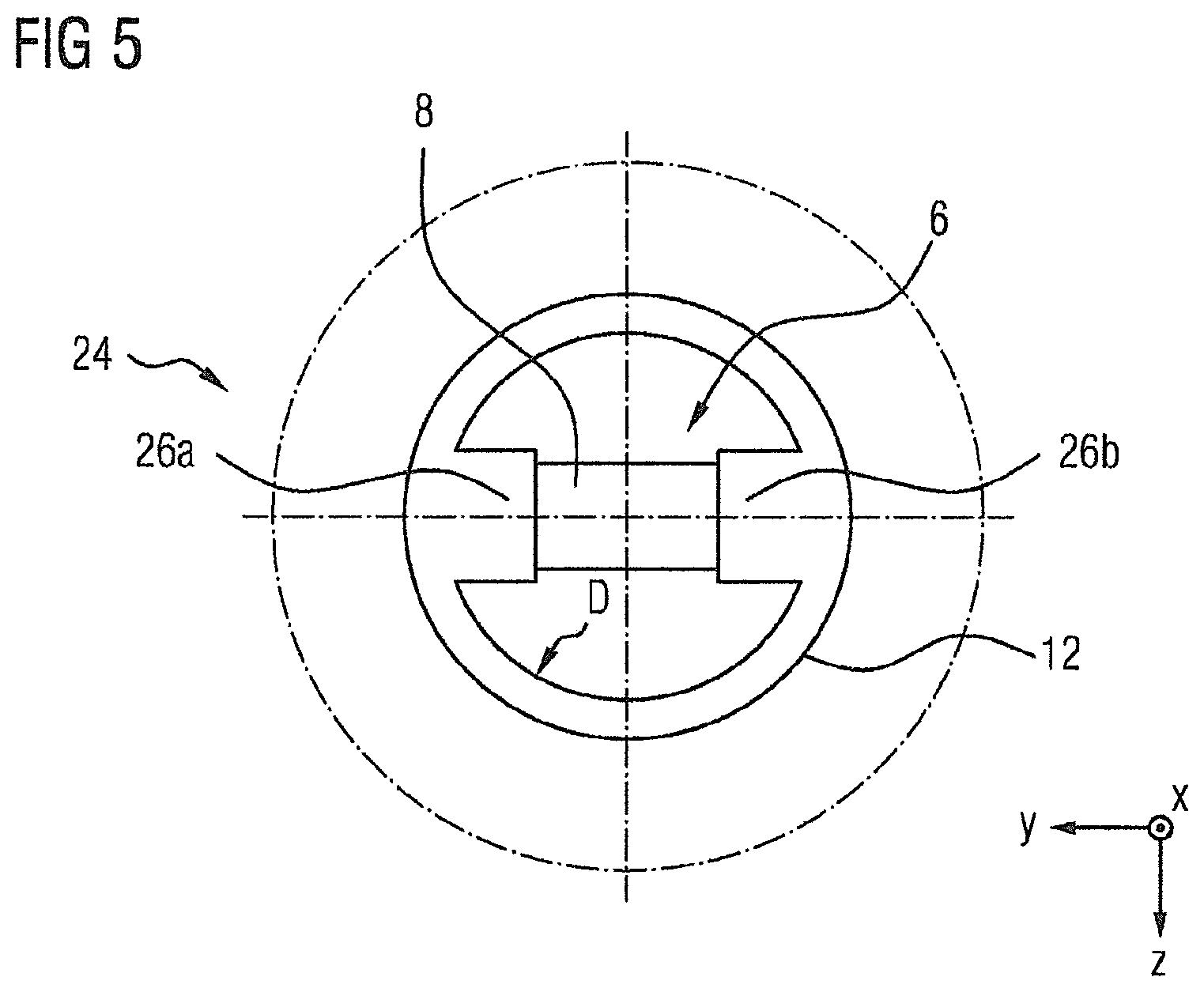
[0039] FIG. 5 shows a plan view relevant to FIG. 3.
DETAILED DESCRIPTION OF THE PRESENTLY PREFERRED EMBODIMENTS
[0040] FIG. 1 illustrates a fuel delivery assembly 2, which is known from the prior art and comprises a screw-spindle pump 4, also referred to as a screw-spindle pump stage, on the suction side. Here, the screw-spindle pump 4 is joined to an electric motor and is rolled together with the latter by a sheet-metal casing or sheet-metal cylinder to form a unit. In this illustration, the electric motor is concealed by the sheet-metal casing or sheet-metal cylinder. Visible on the pump side is an inlet opening 6, via which a fuel is sucked in. Visible in the inlet opening 6 is an elongate insert 8 in the form of a feather key, which functions as an abutment element and against which the screw spindles 14, 16 of the pump 4 are supported during operation and which forms a first abutment for a drive spindle 16 and a second abutment for a running spindle 14.
[0041] FIG. 2 illustrates the pump or pump stage 4, which comprises the drive spindle 16 and the running spindle 14, which runs oppositely with respect to the drive spindle 16. The pump 4 also comprises a pump housing 10 and a pump cover 12 for receiving the two screw spindles 14, 16. Also arranged in the pump cover 12, in a clamping manner, is the aforementioned feather key-type insert 8 which functions as an abutment element and against which the two screw spindles 14, 16 abut.
[0042] Here, the two screw spindles 14, 16 form, together with the pump housing 10, delivery chambers 18, which move from a suction side 20 to a pressure side 22 of the pump 4 as a consequence of a rotation of the screw spindles 14, 16. Or, put differently, the delivery chambers 18 move in the direction of the pressure side 22 as a consequence of a rotation of the screw spindles 14, 16.
[0043] Here, the pump cover 12 has a pump housing section 24 arranged in a manner orthogonal (cf. Y-Y direction or transverse direction) to a longitudinal direction X-X of the pump 4 and from which a peripheral projection extends into the inlet opening 6 of the pump cover 12 in a manner orthogonal to the longitudinal direction X-X. The peripheral projection delimits the inlet opening 6.
[0044] The insert 8 (or the feather key 8) is clamped, or placed in a clamping manner, into the receptacle of the pump cover 12 utilizing the length dimension of the insert, and at the same time bears against two projections 26a, 26b, which extend from the aforementioned peripheral projection into the inlet opening 6 of the pump cover 12 (cf. FIG. 2). The two projections 26a, 26b form a receptacle for the insert 8.
[0045] This type of clamping is associated with chip formation, which has to be accommodated as such on the pump housing side or by the pump cover 12. For this purpose, slots are formed in the receptacle of the cover 12 for the feather key and serve as a collector for the chips. In principle, for this solution, there is the risk of chips being flushed into the pump or pump stage, wherein the chips can contaminate the delivery chambers. Such contamination in turn leads to wear between the screw spindles and the associated pump housing section that is increased for friction-related reasons and that, in the worst case, can even lead to the pump or pump stage being damaged.
[0046] FIG. 3 schematically illustrates a first embodiment of the invention, in which a pump cover 12 produced by injection molding--as part of a pump housing for receiving two screw spindles--is provided with two projections 26a, 26b which are formed sectionally and in a manner orthogonal to a longitudinal direction X-X of the pump cover 12. A first sectionally formed projection 26a and a second sectionally formed projection 26b are in this case formed on a pump housing section 24 in the region of the suction-side end of the pump cover 12 and extend into an inlet opening 6 of the pump cover 12. The two projections 26a, 26b, which are of web-type form, are in this case formed on the pump cover 12 in a manner diametrically opposite one another, wherein an elongate insert 8 in the form of a cuboid composed of, for example, a metal or a ceramic, bears against the two projections 26a, 26b in a clamping manner. Here, the two projections form a receptacle into which the cuboid 8 is clamped utilizing one of the cross-sectional dimensions of the cuboid, that is to say either the width dimension thereof or the height dimension thereof. It can be seen that the cuboid 8, with respect to the longitudinal extent thereof, has at both ends a desired spacing 27a, 27b to the receptacle, and as a result clamping into the receptacle utilizing the length dimension of the cuboid does not occur, avoiding the aforementioned disadvantages known from the prior art.
[0047] The cuboid 8, with respect to its cross section, may in this case have, for example, equal sides. As an alternative to such a square formation of the cuboid cross section, a non-square rectangular cross-sectional formation is also conceivable. With regard to the shaping of the insert 8, numerous variations are in principle conceivable. It is merely necessary to ensure an elongate formation of the insert such that the clamping of the insert into the receptacle can be realized sectionally via either the width dimension of the insert or the height dimension of the insert.
[0048] FIG. 4 schematically illustrates a second embodiment of the invention. In comparison with the first embodiment, sthe second embodiment differs merely in that, above the insert 8 in the illustration shown, that is to say on the inlet side or suction side with respect to the insert 8, provision is made of a web section 28 which connects the two projections 26a, 26b to one another. The web section 28 thus provides a further support for the cuboidal element 8, against which the screw spindles 14, 16 of the pump or pump stage 4 are supported.
[0049] FIG. 5 schematically illustrates a plan view relevant to FIG. 3. The two projections 26a, 26b are visible, these extending from a diameter D, which delimits the inlet opening 6, into the inlet opening 6. Here, the diameter does not necessarily have to be understood in relation to a circular inlet opening, but rather as a contour circumscribing an inlet. The cuboidal insert 8 functioning as an abutment bears between the two projections 26a, 26b.
[0050] In a plan view (not illustrated here) relating to FIG. 4, the cuboidal abutment 8 would be concealed by the web section 28 connecting the two projections 26a, 26b to one another.
[0051] The outer circle illustrated by dash-dotted lines in FIG. 5 illustrates here a section of the pump cover 12 that is flange-like on the pressure side, wherein the flange-like section is rolled together with the electric motor mentioned at the beginning by the sheet-metal casing or sheet-metal cylinder (cf. FIG. 1 and FIG. 2).
[0052] FIGS. 3, 4 and 5 are purely schematic illustrations for illustrating the invention.
[0053] In a further embodiment (not illustrated here), the pump cover 12--analogously to FIG. 2--may have a pump housing section 24 formed in a manner orthogonal (cf. Y-Y direction or transverse direction) to a longitudinal direction X-X of the pump 4 and from which the two projections 26a, 26b extend into the inlet opening 6 of the pump cover 12, for example in a manner orthogonal to the longitudinal direction X-X.
[0054] A common feature of the embodiments in FIGS. 3, 4 and 5 is that the insert 8 is clamped into the receptacle of the pump cover, which receptacle is formed by the two projections 26a, 26b, utilizing a height dimension or width dimension of the insert 8. Here, the receptacle may in principle be provided in a pump housing, or else in a pump cover as part of a pump housing.
[0055] A further common feature of the embodiments in FIGS. 3, 4 and 5 is that the cross-sectional dimension which actually serves for clamping in the use position of the insert 8 may be understood as being the clamping dimension of the insert, wherein the clamping dimension in the use position of the insert is to be understood as being the width dimension.
[0056] Although exemplary embodiments have been discussed in the above description, it should be noted that numerous modifications are possible. Furthermore, it should be noted that the exemplary embodiments are merely examples which are not intended to limit the scope of protection, the applications and the structure in any way. Rather, a person skilled in the art will take from the above description a guideline for implementation of at least one exemplary embodiment, wherein various modifications may be made, in particular with regard to the function and arrangement of the described components, without departing from the scope of protection as can be gathered from the claims and equivalent feature combinations.
* * * * *
D00000
D00001
D00002
D00003
XML
uspto.report is an independent third-party trademark research tool that is not affiliated, endorsed, or sponsored by the United States Patent and Trademark Office (USPTO) or any other governmental organization. The information provided by uspto.report is based on publicly available data at the time of writing and is intended for informational purposes only.
While we strive to provide accurate and up-to-date information, we do not guarantee the accuracy, completeness, reliability, or suitability of the information displayed on this site. The use of this site is at your own risk. Any reliance you place on such information is therefore strictly at your own risk.
All official trademark data, including owner information, should be verified by visiting the official USPTO website at www.uspto.gov. This site is not intended to replace professional legal advice and should not be used as a substitute for consulting with a legal professional who is knowledgeable about trademark law.