Pump Unit
SAUERBIER; Carsten ; et al.
U.S. patent application number 16/628505 was filed with the patent office on 2020-04-30 for pump unit. This patent application is currently assigned to Vetter GmbH. The applicant listed for this patent is Vetter GmbH. Invention is credited to Carsten SAUERBIER, Wilhelm SCHNICKE.
| Application Number | 20200132063 16/628505 |
| Document ID | / |
| Family ID | 59285197 |
| Filed Date | 2020-04-30 |


| United States Patent Application | 20200132063 |
| Kind Code | A1 |
| SAUERBIER; Carsten ; et al. | April 30, 2020 |
PUMP UNIT
Abstract
A pump unit (10) can be carried by an operating person for the pressurized filling of inflatable filling chambers with a fluid, in particular lifting pads (2), blocking pads, tents or the like. The pump unite includes a fluid pump (12), an electric motor (11) for driving the fluid pump (12), a battery (13), a control unit (17) for controlling the operation of the fluid pump, and a connector (18) for the connection of a fluid hose (3) which leads to the filling chamber. A manually actuatable control valve (16) is positioned on the pump unit (10).
| Inventors: | SAUERBIER; Carsten; (Lauf, DE) ; SCHNICKE; Wilhelm; (Bad Munstereifel, DE) | ||||||||||
| Applicant: |
|
||||||||||
|---|---|---|---|---|---|---|---|---|---|---|---|
| Assignee: | Vetter GmbH Zulpich DE |
||||||||||
| Family ID: | 59285197 | ||||||||||
| Appl. No.: | 16/628505 | ||||||||||
| Filed: | July 4, 2017 | ||||||||||
| PCT Filed: | July 4, 2017 | ||||||||||
| PCT NO: | PCT/EP2017/066552 | ||||||||||
| 371 Date: | January 3, 2020 |
| Current U.S. Class: | 1/1 |
| Current CPC Class: | F04B 49/022 20130101; F04B 35/04 20130101; F04B 39/10 20130101; F04B 35/06 20130101; F04B 39/06 20130101; F04B 49/22 20130101 |
| International Class: | F04B 35/04 20060101 F04B035/04; F04B 39/06 20060101 F04B039/06; F04B 39/10 20060101 F04B039/10; F04B 49/02 20060101 F04B049/02; F04B 49/22 20060101 F04B049/22 |
Claims
1-19. (canceled)
20. A pump unit is configured for manual carrying and for pressurized filling of inflatable filling chambers with compressed air, comprising: a fluid pump; an electric motor for operating the fluid pump; an accumulator; a control unit for controlling operation of the fluid pump; a connector for connecting a fluid hose leading to the filling chamber; and a control valve positioned at the pump unit comprising a manifold valve; wherein: the control valve is actuated manually actuatable; the control valve is connected to the control unit via a signal line; and the electric motor is controlled by actuating the control valve.
21. The pump unit according to claim 20, wherein the portable pump unit comprises a housing or a support frame and the control valve is housed in or on the housing or support frame.
22. The pump unit according to claim 20, wherein the control valve is housed in a valve block or is a component of the valve block.
23. The pump unit according to claim 22, wherein the valve block is positioned on the fluid pump.
24. The pump unit according to claim 20, further comprising a pressure measuring device which measures filling pressure of the inflatable filling chamber.
25. The pump unit according to claim 24, wherein the pressure measurement device (24) is located between the connector (18) and the control valve (16).
26. The pump unit according to claim 24, wherein the pressure measurement device is housed in the valve block.
27. The pump unit according to claim 24, wherein the pressure measurement device comprises a display.
28. The pump unit according to claim 24, wherein the pressure measurement device is connected to the control unit via a signal line.
29. The pump unit according to claim 20, wherein at least two control valves are provided at the pump unit, each control valve comprising a connector for connecting a fluid hose leading to one fluid chamber each.
30. The pump unit according to claim 29, wherein a common fluid pump is provided for the at least two control valves.
31. The pump unit according to claim 20, wherein the control valve is a 3/3-way valve.
32. The pump unit according to claim 20, wherein the control valve is a proportional valve.
33. The pump unit according to claim 20, wherein a cooling fan is arranged on the fluid pump.
34. The pump unit according to claim 20, wherein: the filling chamber is filled with fluid in a first operating mode; in a second operating mode, the pressure in the filling chamber is kept at least substantially constant; the control valve for the first operating mode transmits a first signal to the control unit; the control valve for the second operating mode transmits a second signal to the control unit; the control unit detects the signals and controls the electric motor in accordance with the signals.
35. The pump unit according to claim 34, wherein the fluid is discharged from the filling chamber in a third operating mode and the control valve for the third operating mode transmits a third signal to the control unit.
36. The pump unit according to claim 20, wherein the control unit detects a temporal change in pressure and regulates and/or switches on or off the electric motor as a function of detected temporal change in pressure.
37. The pump unit according to claim 20, wherein the chambers comprise particular lifting pads, blocking pads, or tents.
Description
[0001] The present invention relates to a pump unit which can be carried by an operating person and which serves for the pressurized filling of inflatable filling chambers with a fluid, preferably with compressed air, in particular lifting pads, blocking pads, tents or the like, with the features of the preamble of claim 1.
TECHNOLOGICAL BACKGROUND
[0002] During rescue and disaster operations, easy access to the scene of the accident is not always possible, so that heavy equipment is often ruled out. Especially in the case of people buried, jammed and/or trapped, rapid rescue is essential for survival. Lifting pads have established themselves as a tried and tested means of lifting pieces of debris, overturned vehicles or the like. Especially in the case of destroyed buildings, be it through earthquakes, gas explosions, acts of war or the like, or also in the case of accidents with vehicles, lifting pads offer a good rescue possibility.
[0003] Lifting pads are usually inserted into small gaps in their flattened form, for example between pieces of debris, and inflated with compressed air from compressed air bottles. A pressure of up to 12 bar is usually used for operation. The lifting pad thus expands in a given direction, which is determined by the design of the lifting pad. In addition to a compressed air bottle, various other components are required for the use of lifting pads, such as pressure reducers, manometers and connecting hoses between the individual components.
[0004] Rescue workers are exposed to very high stress loads during rescue operations. In addition, rescue operations must be carried out particularly quickly in order to save human lives. For this reason, rescue equipment must be particularly easy and safe to use at the scene of the accident.
CLOSEST PRIOR ART
[0005] A pump unit according to the preamble of claim 1 is known from DE 10 2007 014 467 A1. The pump unit has a control unit, in which the operation of the fluid pump can be controlled by an on/off switch. The on/off switch is located either directly on the control unit housed in the pump unit or on the free end of the hose, which can be connected to the lifting pad. The inflation of the lifting pad is thus effected by actuating the power switch. As a result, fluid is pumped into the pad at maximum power. Particularly in rescue operations, where a lifting pad is used to lift a collapsed wall or the like, for example, this can lead to uncontrolled conditions which endanger a person who has been buried.
OBJECT OF THE PRESENT INVENTION
[0006] The object of the present invention is to provide a pump unit of the generic type which ensures improved safety in use.
Solution of the Problem
[0007] The above problem is solved by the features of claim 1. Appropriate formulations of the present invention are claimed in the subclaims.
[0008] According to the invention, a pump unit which can be carried by an operating person is provided for pressurized filling of inflatable filling chambers with a fluid, preferably air, in particular lifting pads, blocking pads, tents or the like, the pump unit comprising a fluid pump, an electric motor for operating the fluid pump, a battery, a control unit for controlling the operation of the fluid pump, a connector for connecting a fluid hose leading to the filling chamber and a control valve which is positioned on the pump unit and can preferably be actuated manually. By providing a control valve positioned directly on the pump unit, a single operating person operating the pump unit can also carry out a controlled filling of the lifting pad at any time directly at the scene of the operation, so that dangerous conditions of the type mentioned above can be effectively avoided. Valve units to be carried separately can be omitted. The operating person only has to connect the fluid hose to the pump unit and the pad for the rescue operation and can immediately start the rescue operation.
[0009] The fluid pump can advantageously be a compressor, in particular a piston compressor, a turbo compressor, or even, in the case of special filling chambers, a fan.
[0010] The pump unit can advantageously be fitted with a housing or a support frame, whereby the control valve can be accommodated directly in or on the housing or support frame. This ensures that a fully operational pump unit can be easily carried by an operating person and need only be connected to the fluid hose (plug and play). The further advantage of accommodating the control valve in or on the housing or support frame is that no additional components need be carried along with the pump unit. The operating person does therefore not have to worry about connecting several components during the rescue operation, but can immediately concentrate on the person to be rescued.
[0011] The control valve may preferably be housed in, or be part of, a valve block. By housing it in the valve block, the control valve is no longer loose and does not have to be held additionally.
[0012] The valve block and thus the control valve can be easily fixed in or on the housing or support frame.
[0013] In addition, the control valve can be positioned directly on the fluid pump. The control valve and the fluid pump can be directly connected.
[0014] Preferably, a pressure measuring device can be provided on the pump unit which directly detects and displays the filling pressure of the inflatable filling chamber. The pressure measuring device allows the operating person to monitor the inflation directly at the pump unit which operates it, which enables controlled filling. Particularly when filling a lifting pad, controlled lifting of debris pieces is essential to prevent sudden uncontrolled load distributions.
[0015] The pressure measuring device can be advantageously located between the connector and the control valve, so that it is able to directly measure the pressure continuously prevailing in the filling chamber or in the fluid line to the filling chamber. Thus, in order to monitor the filling pressure, the pressure measuring device is also pre-installed at the required location, i.e. on the pump unit.
[0016] Preferably, the pressure measuring device can also be installed in or on the valve block.
[0017] The present invention also makes it possible to connect the control valve to the control unit via a signal line. This allows the current operating mode of the control valve to be transmitted to the control unit. The operating person can thus control the control unit and, for example, the electric motor of the fluid pump, as required, via the control valve. For example, depending on the position of the control valve, the operating person can control the motor speed and thus the delivery rate of the pump. This makes it possible, for example, to lift a load particularly precisely using a lifting pad.
[0018] In addition, the pressure measuring device can also be connected to the control unit via a signal line. Thus, the control unit can, for example, record the pressure curve over time and, e.g., control the electric motor accordingly. Furthermore, a pressure-dependent readjustment of the delivery rate can take place, for example, in the event of a drop in pressure, e.g. in the lifting pad.
[0019] In particular for an automatic or semi-automatic operation of the pump unit to maintain a set pressure or to maintain a desired filling characteristic curve by the control unit, the signal lines between control unit and control valve as well as pressure measuring device can be relevant.
[0020] It may be advantageous to provide a plurality of control valves, in particular at least two, on the pump unit.
[0021] Thus, for example, two lifting pads can be inflated in a controlled manner by one operating person without the need for further components. The simultaneous use of two lifting pads, for example, lends itself to ensure improved control over the load distribution of e.g. pieces of debris to be lifted.
[0022] Preferably, the control valve can be a 3/3-way valve, which has a pump position (pressure build-up), a bypass position (no pressure build-up, no relief) and a bleed position (relief).
[0023] It is particularly advantageous if the control valve is a proportional valve. This allows a proportional valve function that depends on the manual actuation, i.e. on the position of the control unit of the control valve, whereby hard switching movements can be avoided.
[0024] Alternatively, the invention also makes it possible to operate the control valve autonomously from the control unit, if required.
[0025] Advantageously, a cooling fan may be arranged on the fluid pump. This ensures that the fluid pump does not overheat, even when in continuous use.
[0026] Preferably, the functioning of the pump unit is characterized in that in a first operating mode the filling chamber is filled with fluid, in a second operating mode the pressure in the filling chamber is kept at least substantially constant, the control valve for the first operating mode transmits a first signal to the control unit, the control valve for the second operating mode transmits a second signal to the control unit, the control unit detecting the first or second signal, and controls the electric motor in accordance with the first or second signal. In the second operating mode, for example, the electric motor can be switched off with a switch-off signal to save energy in the battery.
[0027] In a third operating mode, fluid can be discharged from the filling chamber. The third operating mode can also be controlled via the control valve. In the third operating mode, the control valve can transmit a third signal to the control unit, whereupon the control unit regulates and/or switches off the electric motor accordingly. This has the advantage that the electric motor is only switched on and consumes energy when fluid is required for pressurized filling of the filling chamber.
[0028] Advantageously, the pressure measuring device can transmit the measured pressure to the control unit, whereby the control unit detects the temporal change of the pressure and, depending on the temporal change of the pressure, sends a switch-on and/or switch-off signal to the electric motor. Thus, by monitoring the pressure, the control unit can, for example, switch on the electric motor in preparation even before the pressurized fluid is required at the control valve.
[0029] In addition to the manual ability to actuate the control valve, it is possible to alternatively or additionally provide for the control unit to actuate the control valve autonomously.
[0030] Advantageously, if the pressure falls below a first limit value, the control unit sends a signal for the first operating mode to the control valve. Thus, in the event of a pressure drop, the inflatable filling chamber is refilled with fluid, so that the pressure again rises above the first limit value. This procedure can be used, for example, if the inflatable filling chamber is to be kept at or above a certain pressure for a long period of time, for example in the case of lifting pads, blocking pads or inflatable tents.
[0031] When a pressure set point is reached, the control unit can preferably send a signal for the second operating mode to the control valve. This allows the pressure to be maintained at the set point by the control unit autonomously through the second operating mode. A previous filling or discharging of the fluid into or out of the inflatable filling chamber is thus terminated.
[0032] Advantageously, if the pressure is exceeded, the control unit can send a signal for the third operating mode to the control valve via a second limit value. In order to counter an unwanted pressure increase, the fluid is discharged from the inflatable filling chamber in the third operating mode. This allows the control unit to autonomously monitor the overpressure protection.
[0033] Particularly when the filling pressure is maintained and monitored over a longer period of time, an operating person can be relieved or replaced by the autonomous regulation of the pressure by the control unit.
DESCRIPTION OF THE INVENTION BASED ON EXEMPLARY EMBODIMENTS
[0034] Advantageous embodiments of the present invention are explained in more detail below on the basis of drawing figures. They show:
[0035] FIG. 1 a very simplified schematic representation of the use of the pump unit when filling a lifting pad for a rescue operation;
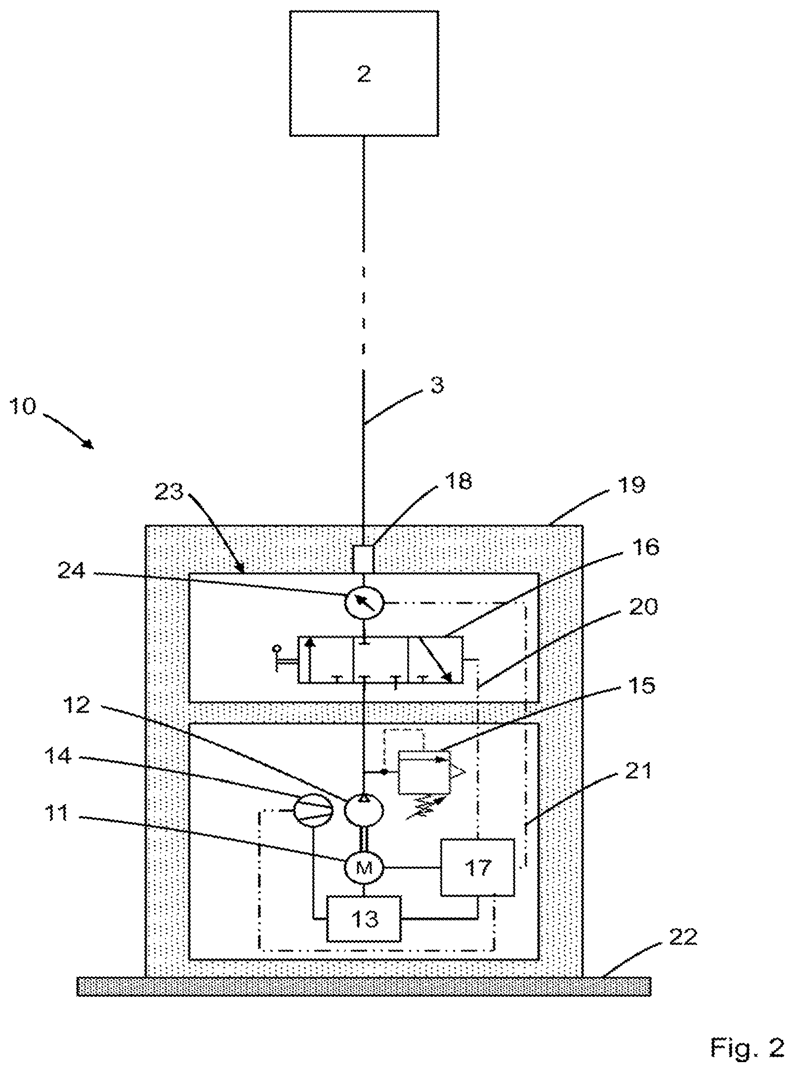
[0036] FIG. 2 a very simplified schematic representation of the pump unit with a valve block;
[0037] FIG. 3 a very simplified schematic representation of the pump unit with two control valves; and
[0038] FIG. 4 an exemplary temporal sequence of the pressure at the pressure measuring device and corresponding operating states of the control valve and the electric motor, e.g. during automatic operation.
[0039] FIG. 1 shows a portable pump unit 10 in an exemplary rescue operation. The operating person can independently carry and operate the portable pump unit 10. The pump unit 10 is connected to a lifting pad 2 via connector 18 by means of a fluid hose 3. The lifting pad 2 is placed between debris parts and is filled with a fluid, e.g. compressed air, in order, for example, to widen a gap between the debris parts. The operating person must carry a device unit in the form of pump unit 10, which already contains all the necessary components for filling inflatable filling chambers, such as a lifting pad. Only one fluid hose connector 3 is required, which is located between the pump unit 10 and the lifting pad 2.
[0040] A more detailed representation of the inventive pump unit 10 according to FIG. 1 is shown in FIG. 2. The pump unit 10 is connected to the lifting pad 2 by means of a fluid hose 3. The pump unit 10 has a support frame 19 for easier transport, which also has a stand 22 for safe placement on the ground.
[0041] The individual components are housed directly on the support frame 19. For example, the pump unit 10 has a fluid pump 12 (e.g. a compressor, especially a piston compressor) to provide the required pressure for filling an inflatable filling chamber, such as here of the lifting bag 2.
[0042] The fluid pump 12 is powered by an electric motor 11 and cooled by a cooling fan 14. The electric motor 11 and the cooling fan 14 are in turn powered by a battery 13. To control the electric motor 11, the pump unit 10 comprises a control unit 17. The fluid pump 12 is also connected to a manually actuatable control valve 16 located directly on the pump unit 10, which enables controlled filling of the lifting pad 2.
[0043] The control valve 16 is housed in a valve block 23, which is also housed on the support frame 19. The valve block 23 is positioned directly on the fluid pump 12. The pump unit 10 has a connector 18 to connect the fluid hose 3 to the pump unit 10 before the start of operation. Connector 18 is connected to control valve 16.
[0044] The control valve 16 is preferably a 3/3-way valve which has a pump position (pressure build-up) in the left valve position, a bypass position (no pressure build-up, no relief) in the center valve position and a bleed position (relief) in the right valve position. Preferably this is a so-called proportional valve.
[0045] In addition, there is a pressure measuring device 24 on valve block 23 between control valve 16 and connector 18 for monitoring and displaying the filling pressure of the lifting pad 2. Moreover, as shown in FIG. 2, a safety valve 15 can be arranged between fluid pump 12 and control valve 16. Advantageously, the safety valve 15 can be a pressure relief valve to protect the pump unit 10 against excessive pressure and to prevent damage.
[0046] The control valve 16 is connected to the control unit 17 via a signal line 20. Signal line 20 can be used, for example, to transmit the current operating mode or the current position of control valve 16 to control unit 17. The control unit 17 can control the electric motor 11 accordingly and switch the electric motor 11 on or off or regulate the power of the electric motor 11, as required.
[0047] In addition, the pressure measuring device 24 can be connected to the control unit 17 via a further signal line 21. The control unit 17 can, for example, record the pressure curve over time.
[0048] If required, a cooling fan 14 can also be arranged on the fluid pump 12. This can also be connected to the control unit 17 via a signal line.
[0049] In a special embodiment, in which autonomous operation of the pump unit 10 is provided, as an alternative or supplement to manual operation, the control unit 17 can transmit control signals to the control valve 16. Depending on the pressure curve, the control unit 17 can therefore regulate a filling, releasing or maintaining of the filling pressure at the control valve 16, depending on the situation, in order, for example, to maintain a set pressure in the inflatable filling chamber, e.g. in a pneumatic tent or a lifting pad for repairs.
[0050] FIG. 3 shows a further embodiment of the pump unit 10 with two control valves 16 integrated in it. Each control valve 16 has a separate connector 18, making it possible to fill two lifting pads 2 simultaneously with a single pump unit 10. The pump unit 10 also includes a support frame 19 with stand 22. All components are housed on the support frame 19. The fluid pump 12, the cooling fan 14, the safety valve 15, the electric motor 11, the battery 13 as well as the control unit 17 are provided in a simple version. The fluid pump 12 is connected to both control valves 16. Each control valve 16 also has a separate pressure measuring device 24. The control unit 17 is connected to the control valves 16 via the signal lines 20 and to the pressure measuring devices 24 via the signal lines 21. The two control valves 16 are accommodated in a common valve block 23, as are the two pressure measuring devices 24. The valve block 23 is arranged or attached directly to the fluid pump 12.
[0051] FIG. 4 shows an exemplary temporal sequence of the measured filling pressure of an inflatable filling chamber at the pressure measuring device 24 and the corresponding operating states of the control valve 16 and the electric motor 11 in automatic or semi-automatic operation. In section I, the pressure drops from the set point, with the control valve 16 on hold and the electric motor 11 switched off. As soon as the pressure drops below the first limit value, the control valve 16 in section II is switched to the first operating mode to fill the filling chamber with fluid. The electric motor 11 is switched on accordingly via the control unit 17. When the set value is reached at the pressure measuring device 24 in section III, the control valve 16 is switched back by the control unit 17 to the second operating mode for maintaining the filling pressure, whereby the electric motor 11 is switched off. In section IV, the control valve 16 is switched to the first operating mode analogously to section II before it receives a signal from the control unit 17 in section V to switch to the second operating mode to maintain the filling pressure. In the event that, despite switching to the second operating mode, there is a further increase in pressure at the pressure measuring device 24 above a second limit value, the control unit 17 switches the control valve 16 to a third operating mode. In section VI, the control valve 16 is in the third operating mode to discharge the fluid from the inflatable filling chamber, while the electric motor 11 is still switched off. When the set point in section VII is reached, control valve 16 is switched by control unit 17 to the second operating mode to maintain the filling pressure, analogous to sections I and III. The control of the control valve 16 and the electric motor 11 in sections VIII and IX is carried out analogously to the control in sections II and III.
REFERENCE SIGN LIST
[0052] 10 Pump unit [0053] 11 Electric motor [0054] 12 Fluid pump [0055] 13 Accumulator Battery [0056] 14 Cooling fan [0057] 15 Safety valve [0058] 16 Control valve [0059] 17 Control unit [0060] 18 Connector [0061] 19 Support frame [0062] 20 Signal line [0063] 21 Signal line [0064] 22 Stand [0065] 23 Valve block [0066] 24 Pressure measurement device [0067] 2 Lifting pad [0068] 3 Fluid hose
* * * * *
D00000
D00001
D00002
D00003
D00004
XML
uspto.report is an independent third-party trademark research tool that is not affiliated, endorsed, or sponsored by the United States Patent and Trademark Office (USPTO) or any other governmental organization. The information provided by uspto.report is based on publicly available data at the time of writing and is intended for informational purposes only.
While we strive to provide accurate and up-to-date information, we do not guarantee the accuracy, completeness, reliability, or suitability of the information displayed on this site. The use of this site is at your own risk. Any reliance you place on such information is therefore strictly at your own risk.
All official trademark data, including owner information, should be verified by visiting the official USPTO website at www.uspto.gov. This site is not intended to replace professional legal advice and should not be used as a substitute for consulting with a legal professional who is knowledgeable about trademark law.