Actuator Arrangement
Cecur; Majo
U.S. patent application number 16/629047 was filed with the patent office on 2020-04-30 for actuator arrangement. The applicant listed for this patent is Eaton Intelligent Power Limited. Invention is credited to Majo Cecur.
| Application Number | 20200131949 16/629047 |
| Document ID | / |
| Family ID | 59676626 |
| Filed Date | 2020-04-30 |


View All Diagrams
| United States Patent Application | 20200131949 |
| Kind Code | A1 |
| Cecur; Majo | April 30, 2020 |
ACTUATOR ARRANGEMENT
Abstract
An actuator arrangement for controlling a first latching arrangement of a first dual body rocker arm for controlling an intake valve of an internal combustion engine, and for controlling a second latching arrangement of a second dual body rocker arm for controlling an exhaust valve of the internal combustion engine, the first and second dual body rocker arms each including a first body, a second body, and the latching arrangement controllable to latch and unlatch the first body and the second body. The actuator arrangement includes: an actuation source; and an actuation transmission arrangement for transmitting movement of the actuation source to both the first latching arrangement and the second latching arrangement. In use, movement of the actuation source causes, via the actuation transmission arrangement, control of the first latching arrangement and of the second latching arrangement in common.
| Inventors: | Cecur; Majo; (Rivarolo Canavese, IT) | ||||||||||
| Applicant: |
|
||||||||||
|---|---|---|---|---|---|---|---|---|---|---|---|
| Family ID: | 59676626 | ||||||||||
| Appl. No.: | 16/629047 | ||||||||||
| Filed: | July 7, 2018 | ||||||||||
| PCT Filed: | July 7, 2018 | ||||||||||
| PCT NO: | PCT/EP2018/068455 | ||||||||||
| 371 Date: | January 7, 2020 |
| Current U.S. Class: | 1/1 |
| Current CPC Class: | F01L 2001/0537 20130101; F01L 1/18 20130101; F01L 2001/186 20130101; F01L 1/185 20130101; F01L 1/2405 20130101; F01L 2013/103 20130101; F01L 2013/001 20130101; F01L 1/267 20130101; F01L 13/00 20130101; F01L 31/08 20130101; F01L 2800/08 20130101; F01L 13/0005 20130101; F01L 2305/00 20200501 |
| International Class: | F01L 1/18 20060101 F01L001/18; F01L 13/00 20060101 F01L013/00; F01L 1/26 20060101 F01L001/26; F01L 31/08 20060101 F01L031/08 |
Foreign Application Data
| Date | Code | Application Number |
|---|---|---|
| Jul 7, 2017 | GB | 1710960.4 |
Claims
1. An actuator arrangement for controlling a first latching arrangement of a first dual body rocker arm for controlling an intake valve of an internal combustion engine, and for controlling a second latching arrangement of a second dual body rocker arm for controlling an exhaust valve of the internal combustion engine, the first and second dual body rocker arms each comprising a first body, a second body, and the latching arrangement controllable to latch and unlatch the first body and the second body, the actuator arrangement comprising: an actuation source; and an actuation transmission arrangement configured to transmit movement of the actuation source to both the first latching arrangement and the second latching arrangement, wherein, in use, movement of the actuation source is configured to cause, via the actuation transmission arrangement, control of the first latching arrangement and of the second latching arrangement in common.
2. The actuator arrangement according to claim 1, wherein the actuation transmission arrangement is configured to transmit movement of the actuation source to a plurality of the first latching arrangements and a plurality of the second latching arrangements.
3. The actuator arrangement according to claim 1, wherein the actuation transmission arrangement comprises: a first shaft comprising a first cam configured to control the latching arrangement of the first dual body rocker arm; and a second shaft comprising a second cam configured to control the latching arrangement of the second dual body rocker arm, wherein the actuation source is common to the first shaft and the second shaft; and wherein, in use, a rotation of the actuation source is configured to cause the first shaft and the second shaft to rotate, thereby to change an orientation of the first cam and the second cam relative to the first latching arrangement and the second latching arrangement respectively, so as to control the first latching arrangement and the second latching arrangement in common.
4. The actuator arrangement according to claim 3, wherein an axis of the rotation of the actuation source is substantially perpendicular to an axis of rotation of the first shaft and the second shaft.
5. The actuator arrangement according to claim 3, wherein the actuation transmission arrangement comprises a gear mechanism configured to translate a continuous rotation of the actuation source into an intermittent rotation of the first shaft and the second shaft in common in steps of a predefined degree.
6. The actuator arrangement according to claim 3, wherein the first shaft and the second shaft each comprise a plurality of cams configured to control a respective plurality of the latching arrangements of a respective plurality of the dual body rocker arms, and wherein each of the plurality of cams have a different shape so as to allow control on a per rocker arm basis.
7. The actuator arrangement according to claim 1, wherein the actuation source comprises an electric motor.
8. A valve train assembly, comprising: the actuator arrangement according to claim 1; the intake valve and the exhaust valve; and the first and second dual body rocker arms, each comprising a first body, a second body, and the latching arrangement moveable to latch and unlatch the first body and the second body, the first rocker arm being configured to control the intake valve and the second rocker arm being configured to control the exhaust valve.
9. The valve train assembly according to claim 8, wherein the intake valve and the exhaust valve are of a common cylinder of an internal combustion engine.
10. The valve train assembly according to claim 8, further comprising: a plurality of the first dual body rocker arms configured to control a respective plurality of intake valves of a respective plurality of cylinders of an internal combustion engine; and a plurality of the second dual body rocker arms arranged configured to control a respective plurality of exhaust valves of the respective plurality of cylinders of the internal combustion engine, wherein the actuation transmission arrangement is configured to transmit movement of the actuation source to the latching arrangements of each of the plurality of first dual body rocker arms and the plurality of second dual body rocker arms.
11. The valve train assembly according to claim 8, wherein each dual body rocker arm is configured to provide for cylinder deactivation.
Description
CROSS-REFERENCE TO PRIOR APPLICATIONS
[0001] This application is a U.S. National Phase application under 35 U.S.C. .sctn. 371 of International Application No. PCT/EP2018/068455, filed on Jul. 7, 2018, and claims benefit to British Patent Application No. GB 1710960.4, filed on Jul. 7, 2017. The International Application was published in English on Jan. 10, 2019 as WO/2019/008181 under PCT Article 21(2).
FIELD
[0002] The present invention relates to valve train assemblies of internal combustion engines, specifically to actuator arrangements for switchable engine or valve train components of a valve train assembly.
BACKGROUND
[0003] Internal combustion engines may comprise switchable engine or valve train components. For example, valve train assemblies may comprise a switchable rocker arm to provide for control of a valve (for example control of an intake or exhaust valve opening) by alternating between at least two or more modes of operation (e.g. valve-lift modes). Such rocker arms typically involve multiple bodies, such as an inner arm and an outer arm. These bodies are latched together to provide one mode of operation (e.g. a first valve-lift mode) and are unlatched, and hence can pivot with respect to each other, to provide a second mode of operation (e.g. a second valve-lift mode). For example, in a first valve-lift mode the rocker arm may provide for valve opening, whereas in the second valve-lift mode the rocker arm may deactivate valve opening. This can be useful, for example, in applications such as cylinder deactivation. Typically, a moveable latch pin is used and actuated and de-actuated to switch between the two modes of operation.
SUMMARY
[0004] In an embodiment, the present invention provides an actuator arrangement for controlling a first latching arrangement of a first dual body rocker arm for controlling an intake valve of an internal combustion engine, and for controlling a second latching arrangement of a second dual body rocker arm for controlling an exhaust valve of the internal combustion engine, the first and second dual body rocker arms each comprising a first body, a second body, and the latching arrangement controllable to latch and unlatch the first body and the second body, the actuator arrangement comprising: an actuation source; and an actuation transmission arrangement configured to transmit movement of the actuation source to both the first latching arrangement and the second latching arrangement, wherein, in use, movement of the actuation source is configured to cause, via the actuation transmission arrangement, control of the first latching arrangement and of the second latching arrangement in common.
BRIEF DESCRIPTION OF THE DRAWINGS
[0005] The present invention will be described in even greater detail below based on the exemplary figures. The invention is not limited to the exemplary embodiments. Other features and advantages of various embodiments of the present invention will become apparent by reading the following detailed description with reference to the attached drawings which illustrate the following:
[0006] FIG. 1 illustrates schematically a perspective view of a valve train assembly according to a first example;
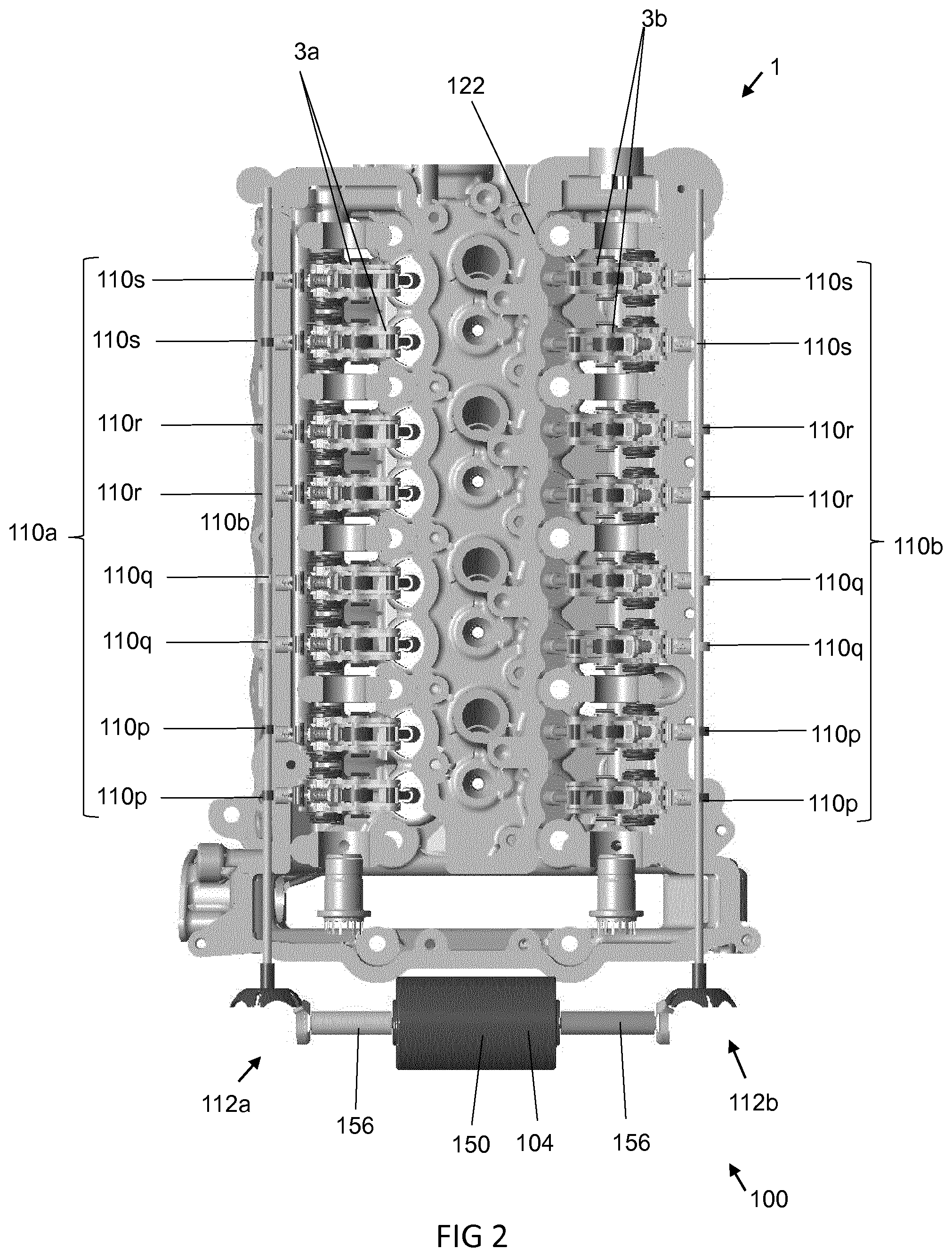
[0007] FIG. 2 illustrates schematically a plan view of a valve train assembly according to the first example;
[0008] FIG. 3 illustrates schematically a perspective view of a valve train assembly according to the first example;
[0009] FIG. 4 illustrates schematically a side view of a valve train assembly according to the first example;
[0010] FIG. 5 illustrates schematically a sectional view of a valve train assembly according to the first example;
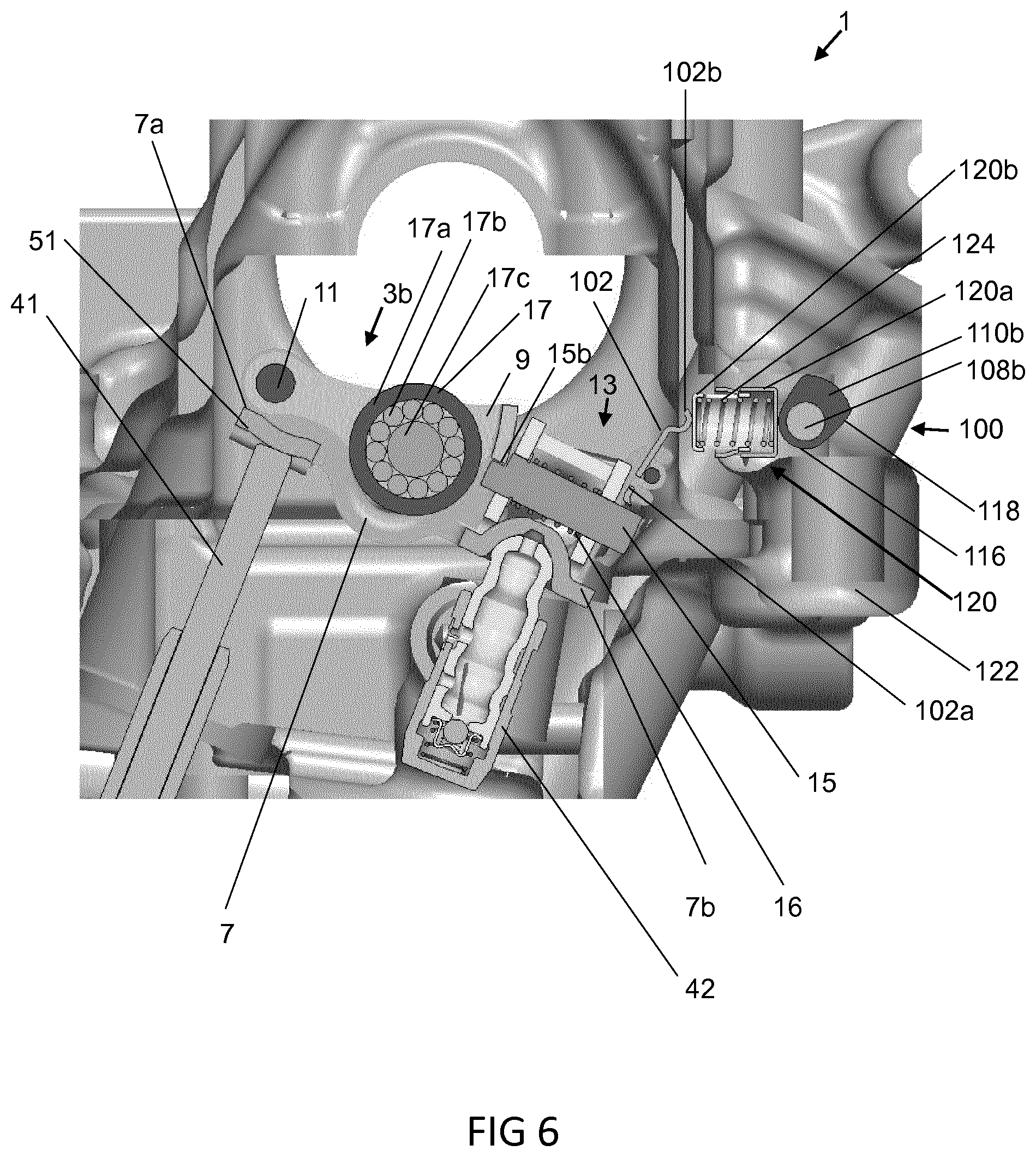
[0011] FIG. 6 illustrates schematically a detail of the sectional view of FIG. 5;
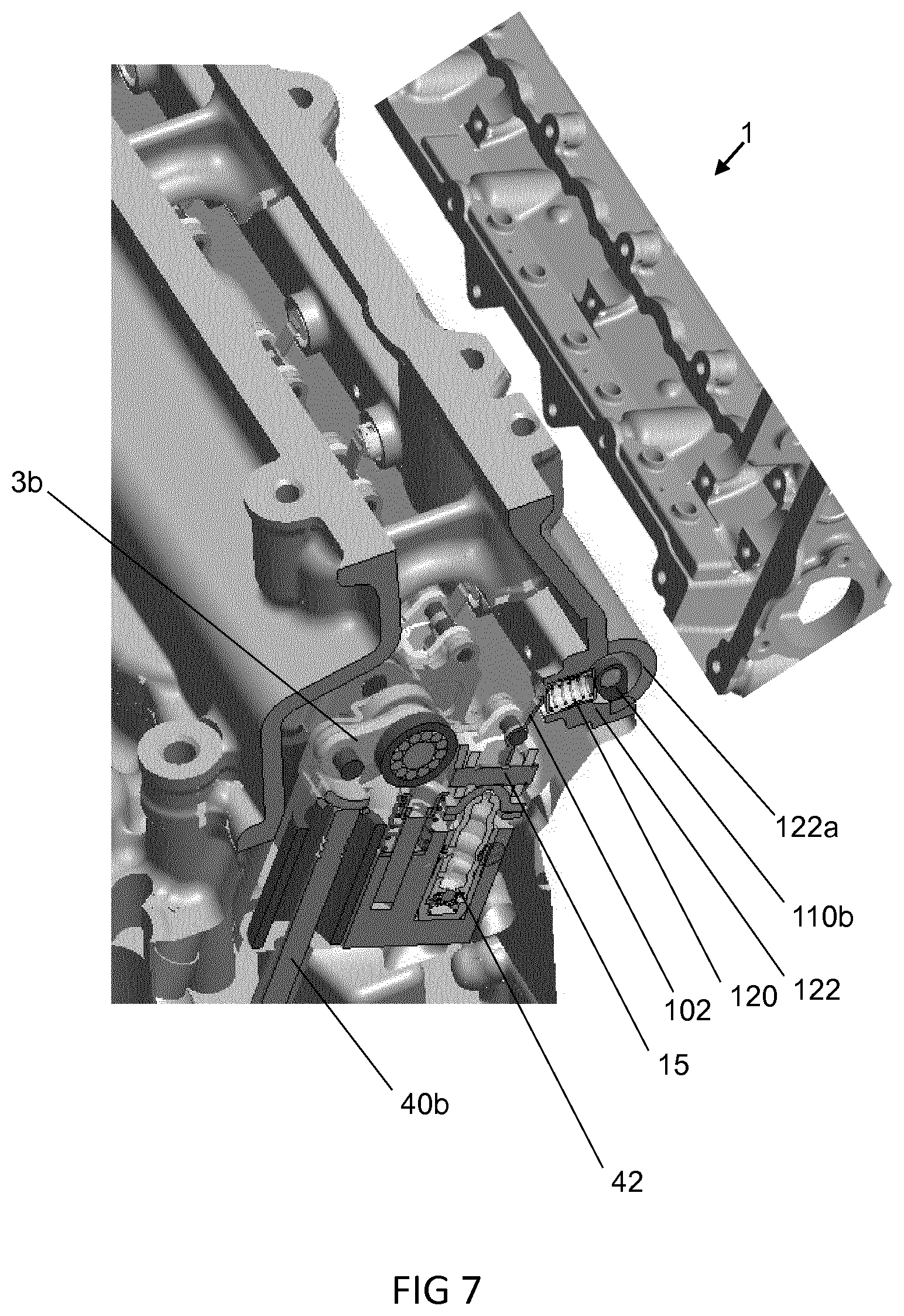
[0012] FIG. 7 illustrates schematically a perspective cutaway view of a valve train assembly according to a first example;
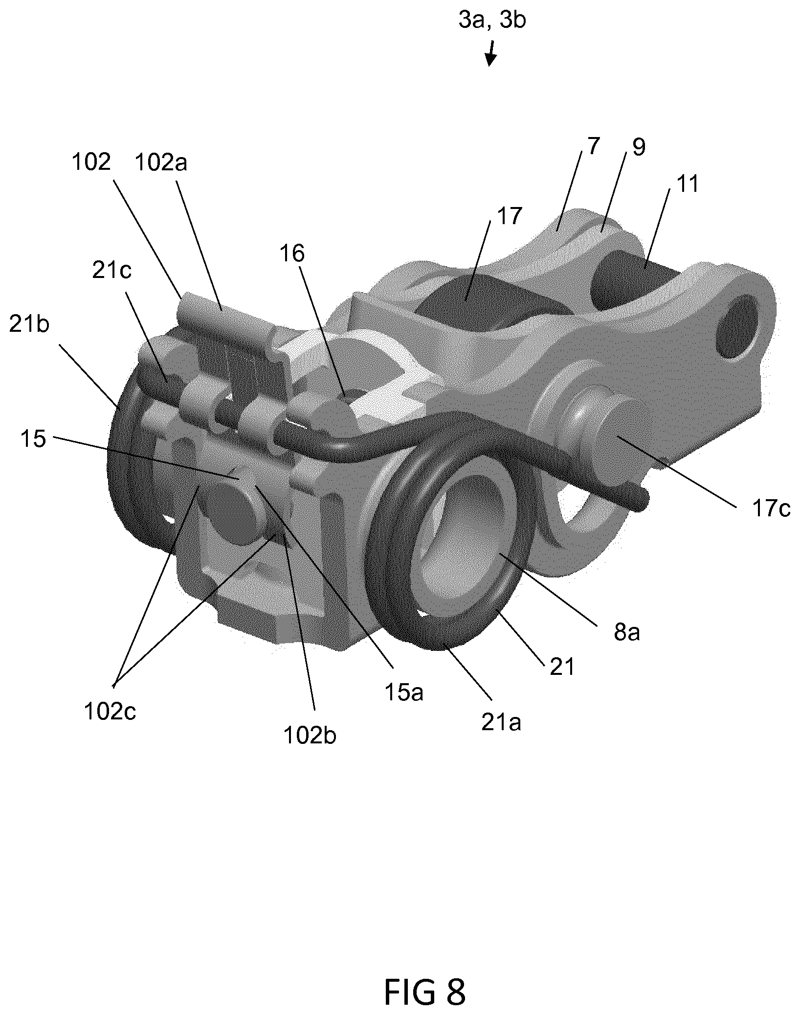
[0013] FIG. 8 illustrates schematically a perspective view of a dual body rocker arm according to an example;
[0014] FIG. 9 illustrates schematically an exploded view of a dual body rocker arm of FIG. 8;
[0015] FIG. 10 illustrates schematically a table of different cylinder operating modes for different cam orientations;
[0016] FIG. 11 illustrates schematically a detail of a perspective view of the valve train assembly according to the first example;
[0017] FIG. 12 illustrates schematically a perspective view of a gear mechanism according to an example;
[0018] FIG. 13 illustrates schematically a side view of a valve train assembly according to a second example;
[0019] FIG. 14 illustrates schematically a sectional view of an actuation source according to the second example;
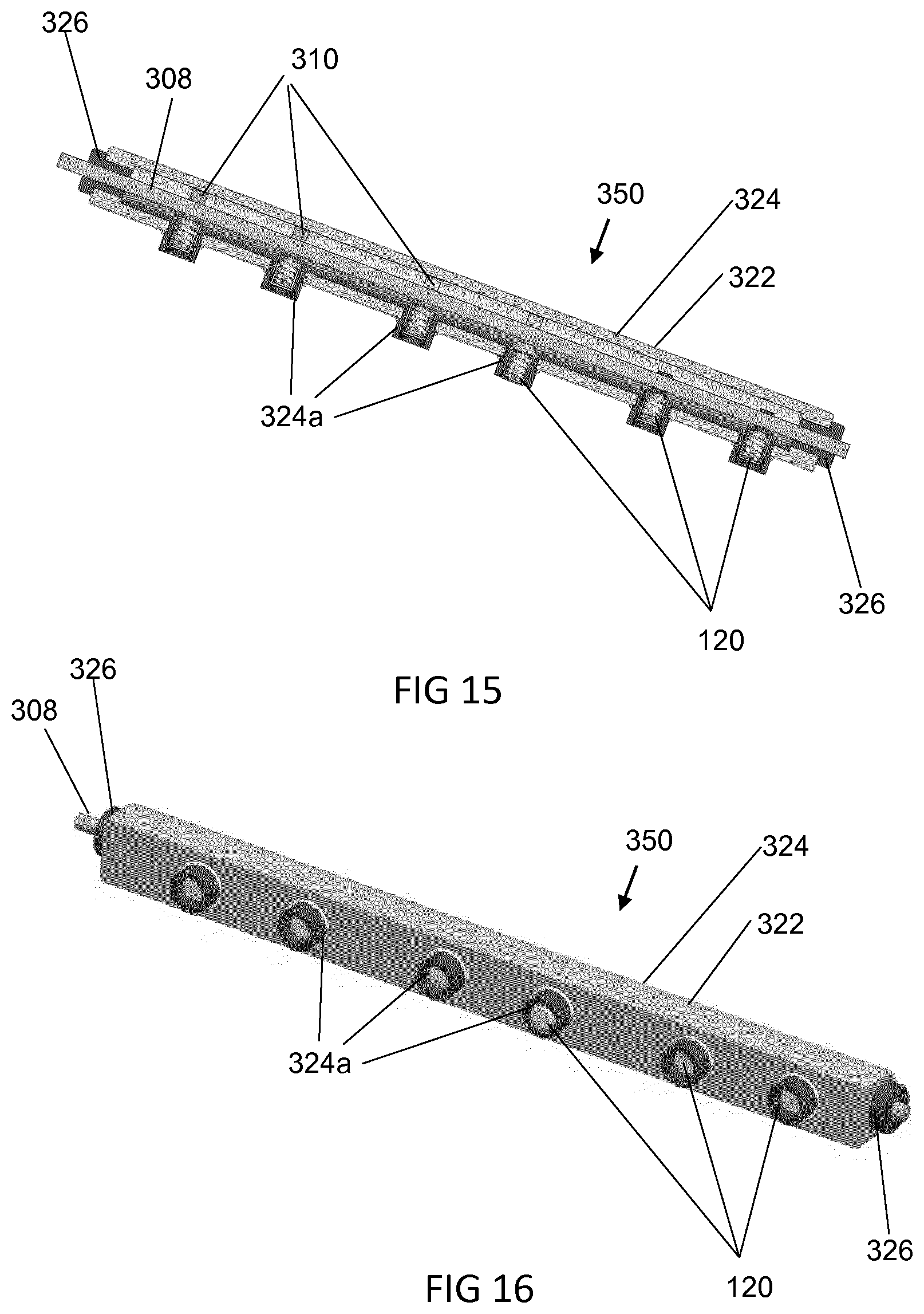
[0020] FIG. 15 illustrates schematically a sectional view of an actuation assembly according to a third example;
[0021] FIG. 16 illustrates schematically a perspective view of the actuation assembly of FIG. 15;
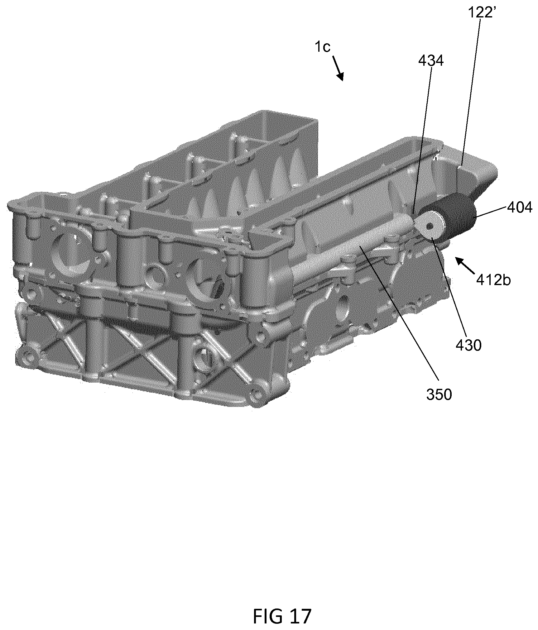
[0022] FIG. 17 illustrates schematically a perspective view of a valve train assembly according to a fourth example;
[0023] FIG. 18 illustrates schematically a cutaway view of the valve train assembly of FIG. 17;
[0024] FIG. 19 illustrates schematically two gear mechanisms according to the fourth example;
[0025] FIG. 20 illustrates schematically a perspective view of a valve train assembly according to a fifth example;
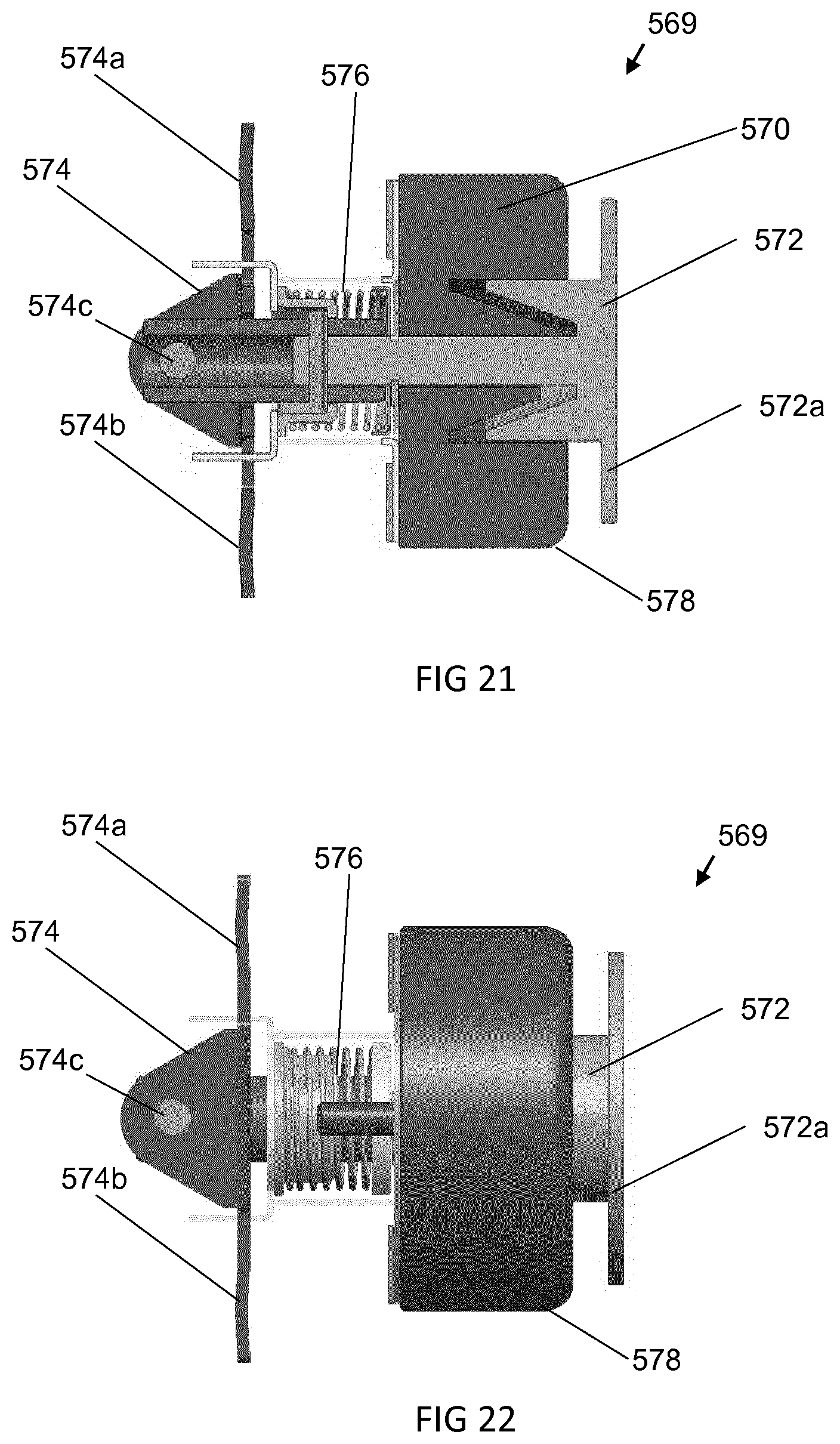
[0026] FIG. 21 illustrates schematically a sectional view of an actuator according to the fifth example;
[0027] FIG. 22 illustrates schematically a side view of the actuator of FIG. 22;
[0028] FIGS. 23 and 24 illustrate schematically perspective views of the actuator of FIG. 21, in different configurations;
[0029] FIG. 25 illustrates schematically a cutaway view of the valve train assembly according to the fifth example; and
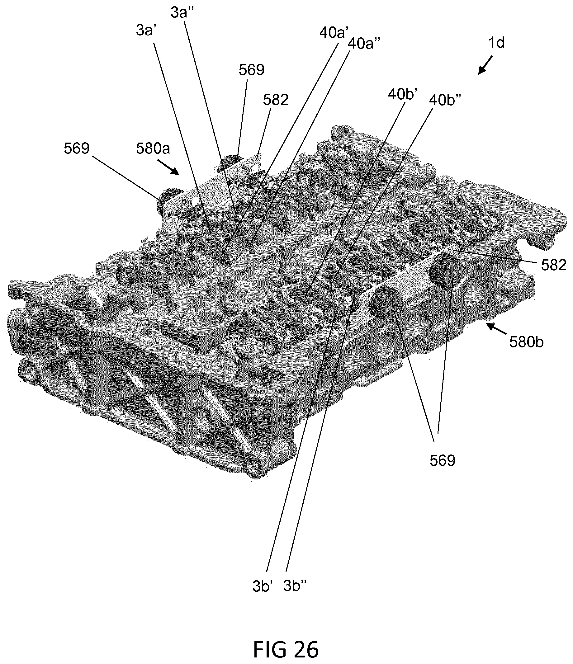
[0030] FIG. 26 illustrates schematically a perspective view of the valve train assembly according to the fifth example.
DETAILED DESCRIPTION
[0031] Throughout, like reference signs denote like features.
[0032] Referring to FIGS. 1 to 12, a first example valve train assembly 1 comprises dual body rocker arms 3 a (hereinafter, simply, rocker arms) for controlling intake valves 40a, and rocker arms 3b for controlling exhaust valves 40b, of cylinders of an internal combustion engine. The valve train assembly 1 is for an inline-four (1-4) internal combustion engine having four cylinders. There are a total of eight intake valves 40a, two for each cylinder, and eight exhaust valves 40b, again, two for each cylinder.
[0033] The valve train assembly 1 comprises a first cam shaft 44a comprising cams 43a, one for each intake valve 40a, and a second cam shaft 44b comprising cams 43b, one for each exhaust valve 40b. Each cam 43a, 43b comprises a base circle 43a', 43b' and a lift profile 43a'', 43b''. The lift profiles 43a'' of the first cam shaft 44a are arranged to cause opening of the respective intake valves 40a, via the rocker arms 3a, at the appropriate times in the engine cycle. Similarly, lift profiles 43b'' of the second cam shaft 44b are arranged to cause opening of the respective exhaust valves 40b, via the rocker arms 3b, at the appropriate times in the engine cycle.
[0034] The valve train assembly 1 comprises an actuation arrangement 100. In broad overview, the actuation arrangement 100 is arranged to control the rocker arms 3 a, 3b to provide either a first valve-lift mode, or a second valve-lift mode.
[0035] As more clearly seen in FIGS. 6, 8 and 9, each rocker arm 3a, 3b comprises an outer body 7 and an inner body 9 that are pivotably connected together at a pivot axis 11. A first end 7a of the outer body 7 contacts a valve stem 41a, 41b of the valve 40a, 40b and a second end 7b of the outer body 7 contacts a hydraulic lash adjuster (HLA) 42. The HLA 42 compensates for lash in the valve train assembly 1. The outer body 7 is arranged to move or pivot about the HLA 42. The outer body 7 contacts the valve stem 41 a, 4 lb via a foot portion 51. Each rocker arm 3a, 3b further comprises at the second end 7b of the outer body 7 a latching arrangement 13 comprising a latch pin latch pin 15 that can be urged between a first position in which the outer body 7 and the inner body 9 are latched together and hence can move or pivot about the HLA 42 as a single body, and an second position in which the inner body 9 and the outer body 7 are unlatched and hence can pivot with respect to each other about the pivot axis 11.
[0036] Each inner body 9 is provided with an inner body cam follower 17, for example, a roller follower 17 for following the cams 43a, 43b on the cam shaft 44a, 44b. The roller follower 17 comprises a roller 17a and needle bearings 17b mounted on a roller axle 17c. Each valve 40a, 40b comprises a valve spring for urging the rocker arm 3 a, 3b against the cams 43 a, 43b of the cam shaft 44.
[0037] Each rocker arm further comprises a return spring arrangement 21 for returning the inner body 9 to its rest position after it is has pivoted with respect to the outer body 7. The return spring 21 is a torsional spring supported by the outer body 7.
[0038] When the latch pin 15 of a rocker arm 3 a, 3b is in the latched position (as per e.g. FIG. 6), that rocker arm 3a, 3b provides a first primary function, for example, the valve 40a, 40b it controls is activated as a result of the rocker arm 3a, 3b pivoting as a whole about the HLA 42 and exerting an opening force on the valve 40a, 40b it controls. For example, when the latch pin of the rocker arm 3 a is in the latched position, and hence the inner body 9 and the outer body 7 are latched together, when the cam shaft 44a, 44b rotates such that the lift profile 43a'', 43b'' of the cam 43a, 43b engages the inner body cam follower 17, the rocker arm 3a is caused to pivot about the HLA 42 against the valve spring, and hence control the valve 40a to open.
[0039] When the latch pin 15 of a rocker arm 3 a, 3b is in the un-latched position, that rocker arm 3a, 3b provides a second secondary function, for example, the valve 40a, 40b it controls is de-activated as a result of lost motion absorbed by the inner body 9 pivoting freely with respect to the outer body 7 about the pivot axis 11 and hence no opening force being applied to the valve 40a, 40b. For example, when the latch pin 15 of the rocker arm 3a is in the un-latched position, and hence the inner body 9 and the outer body 7 are unlatched, when the cam shaft 44 rotates such that the lift profile 43a'', 43b'' of the cam 43, 44 engages the inner body cam follower 17, the inner body 9 is caused to pivot with respect to the outer body 7 about the pivot axis 11 against the return spring arrangement 21, and hence the rocker arm 3 a is not caused to pivot about the HLA 42, and hence the valve 40a, 40b does not open. The cylinder associated with the valve 40a may thereby be deactivated (also referred to as cylinder deactivation).
[0040] In such a way, for example, the position of the latch pin may be used to control whether or not the rocker arm 3a, 3b is configured for cylinder deactivation.
[0041] As mentioned above, the rocker arm 3a, 3b comprises the inner body 9, the outer body 7, and the latching arrangement 13 moveable to latch and unlatch the inner body 9 and the outer body 7. The latching arrangement 13 is at an opposite side of the rocker arm 3 a, 3b to the pivot axis 11. The latching arrangement 13 comprises the latch pin 15 moveable between a first position in which the latch pin 15 latches the inner body 9 and the outer body 7 together and a second position in which the inner body 9 and the outer body 9 are un-latched. The latching arrangement 13 comprises a lever 102 mounted for pivotal motion relative to the outer body 7. A first end 102a of the lever 102 contacts the latch pin 15, and a second end 10b of the lever 102 is for contacting the actuation arrangement 100. In broad overview, when the actuation arrangement 100 exerts a force on the second end 102b of the lever, the lever 102 is caused to pivot such that the first end 102a of the lever exerts a force on the latch pin 15, thereby moving the latch pin from the first (latched) position to the second (unlatched) position.
[0042] The lever 102 is arranged to orient the latch pin 15 rotationally with respect to the outer body 7. Specifically, as best seen in FIGS. 8 and 9, the second end 102b of the lever 102 defines protrusions 102c, and the latch pin 15 defines transverse slots 15a into which the protrusion 102c is received. This prevents the latch pin 15 from rotating relative to the lever 102, and thereby orients the latch pin 15 rotationally with respect to the lever 102. Specifically, the latch pin 15 is orientated so that a shelf 15b of the latch pin 15 for engaging with the inner body 9 when the latch pin 15 is in the first position, faces towards the inner body 9.
[0043] As mentioned above, the rocker arm 3 a, 3b comprises a torsional biasing means or spring 21 supported by the outer body 7 and arranged to bias the inner body 9 relative to the outer body 7. As best seen in FIGS. 8 and 9, the torsional spring 21 (also known as a torsional lost motion spring) comprises two coiled sections 21a, 21b arranged around and supported by protrusions 8a, 8b on opposite sides of the outer body 7, and a non-coiled section 21c joining the two coiled sections, 21a, 21b and extending transversely across the outer body 7. The lever 102 is mounted on the non-coiled section 21c of the torsional biasing means 21, for pivotal motion relative to the first body 7. The lever 102 is mounted on the non-coiled section 21c of the torsional spring 21 at a point along the lever 102 between the first end 102a and the second end 102b of the lever 102. The lever 102 converts a pushing force on the first end 102a of the lever into a force that pulls the latch pin 15 away from the inner body 9, thereby to move the latch pin 15 from the first (latched) position to the second (unlatched) position.
[0044] The latching arrangement 13 comprises a biasing means or return spring 16 arranged to bias the latch pin 15 towards the first position. As a result, the default configuration of the rocker arm 3 a, 3b is that the inner body 9 and the outer body 7 are latched together to provide the first primary function. The rocker arm 3 a is arranged such that an actuation arrangement 100 can cause the latch pin 15 to move from the first position to the second position against the return spring 16. The return spring 16 has an associated washer 16a.
[0045] As mentioned above, the outer body 7 comprises protrusions 8a, 8b to support the torsional spring 21. The protrusions 8a, 8b are formed integrally with the outer body 7. More specifically the protrusions 8a, 8b are formed from the outer body 7. For example, the protrusions 8a, 8b and the outer body 8 are formed from a single sheet of material, such as metal. For example, the protrusions 8a, 8b and the outer body 7 are formed from a stamped metal sheet. For example, a method of manufacturing the rocker arm 3 a, 3b may comprise providing a sheet of material; and stamping the sheet of material to form the protrusions 8a, 8b. The inner body 9 may also be metal sheet stamped.
[0046] The torsional spring 21 is arranged to bias the inner body 9 relative to the outer body 7 from a position in which the inner body 9 is pivoted away from the outer body 7, towards a position in which the inner body 9 is aligned with the outer body 9. The torsional biasing means 21 is arranged around each protrusion 8a, 8b. Specifically, each protrusion 8a, 8b comprises a substantially cylindrical cuff 8a, 8b, the cuff 8a, 8b defining a curved surface 8c by which the torsional biasing means 21 is supported. Each protrusion 8a, 8b is located towards an end 7b of the outer body 7 opposite to that end 7a where the inner body 9 is connected to the outer body 7.
[0047] As mentioned above, the actuation arrangement 100 controls the latching arrangement 13 of the rocker arms 3a, 3b, so as to control the position of the latch pins 15, so as to control whether or not the rocker arms 3a, 3b are configured for cylinder deactivation.
[0048] As best seen in FIGS. 1 to 4, the actuation arrangement 100 comprises an actuation source 104, and an actuation transmission arrangement 106. The actuation arrangement 100 is incorporated in the cam carrier 122 of the engine. The actuation transmission arrangement 106 is arranged to transmit movement of the actuation source 104 to the latching arrangements 13 of the rocker arms 3 a, 3b of both the intake valves 40a and the exhaust valves 40b. In other words, the actuation source 104 is common to the latching arrangements 13 of the rocker arms 3 a, 3b of both the intake valves 40a and the exhaust valves 40b. In broad overview, in use, movement of the actuation source 104 causes, via the actuation transmission arrangement 106, control of the latching arrangements 13 of the exhaust valve and intake valve rocker arms 3a, 3b, in common.
[0049] The actuation transmission arrangement 106 comprises a first shaft 108a comprising a first set of cams 110a for controlling the latching arrangements 13 of the rocker arms 3 a controlling the intake valves 40a. The actuation transmission arrangement 106 comprises a second shaft 108b comprising a second set of cams 110b for controlling the latching arrangements 13 of the rocker arms 3b controlling the exhaust valves 40b. The actuation source 104 is common to the first shaft 108a and the second shaft 108b. The axis of the rotation of the actuation 104 source is perpendicular to an axis of rotation of the first shaft 108a and to an axis of rotation of the second shaft 108b. In use, a rotation of the actuation source 104 causes, via gear mechanisms 112a, 112b, the first shaft 108a and the second shaft 108b to rotate, thereby to change an orientation of the first set of cams 110a and the second set of cams 110b relative the latching arrangements 13 of the rocker arms 3 a, 3b of the intake valves 40a and the exhaust valves 40b, respectively, so as to control those latching arrangements 13.
[0050] As best seen in FIG. 6, each cam 110 has an associated compliance arrangement 120 intermediate of the cam 110 and the latching arrangement 13 of the associated rocker arm 3a, 3b. The compliance arrangement 120 is supported by a main body 122 external to the rocker arm 3a,3b. Specifically, the compliance arrangement 120 is supported by the cam carrier 122. The shafts 108a, 108b and cams 110a, 110b are housed in a housing 122a connected to the cam carrier 122 adjacent to the compliance arrangement 120 (see also FIG. 7). The compliance arrangement 120 comprises a first portion 120a for contacting with the cam 110, a second portion 120b for contacting with the latching arrangement 13. The second portion 120b is moveable relative to the first portion 120a. The compliance arrangement comprises a biasing means 124 arranged to bias the first portion 120a and the second portion 120b away from one another. The compliance device 120 transmits an actuation force from the cam 110 to the latching arrangement 13 of the rocker arm.
[0051] Each cam 110 has a base circle 116 and a raised profile 118. When the cam 110 is orientated such that the base circle 116 is engaged with the compliance arrangement 120, no actuation force is transmitted to the latching arrangement 13, and hence the rocker arm 3a, 3b remains in its default, latched configuration. When the shaft 108 is rotated such that the raised profile 118 is engaged with the compliance arrangement 120, the raised profile 118 applies a force, via the compliance arrangement 120, to the latching arrangement 13. If the latching arrangement 13 is free to move, this force will cause the latch pin 15 to move from its first, default position to its second position in which the inner body 9 and the outer body 7 are unlatched, and hence in a cylinder deactivation configuration. However, if the latching arrangement 13 is in a non-moveable state, the biasing means 124 becomes biased by the cam 110, and the biasing means 124 causes the latching arrangement 13 to move from its first position to its second position when the latching arrangement 13 is in a moveable state again. For example, the latching arrangement 13 may be in a non-moveable state when the engine cycle is such that the inner body 9 is forced against the latch pin 15 so as to hold it firmly in place. The biasing means 124 if biased by the cam 110 in this time will then, once the engine cycle has moved on such that the inner body 9 is no longer forced against the latch pin 15, cause the latch pin 15 to move from the first position to the second position, and hence configure the rocker arm 3 a, 3b for cylinder deactivation. The compliance arrangement 120 thereby allows for the actuation of the latching arrangement to be effected as soon as it is physically possible, and hence can simplify timing requirements of actuating the latching arrangements 13.
[0052] As best seen in FIG. 3, the cams 110 of the first set of cams 110a have different shapes to allow control of the latching arrangements 13 on a per cylinder basis. Similarly, the cams 110 of the second set of cams 110b have different shapes to allow control on a per cylinder basis. The cams 110 of the first set 110a and the second set 110b that are associated with the same cylinder have the same shape, so as to allow for deactivation of that cylinder based on deactivation of both the intake and exhaust valves of that cylinder.
[0053] Specifically, first cams 11 Op for controlling rocker arms 3a, 3b of valves 40a, 40b of a first cylinder have a first shape, second cams 1 lOq for controlling rocker arms 3a, 3b of valves 40a, 40b of a second cylinder have a second shape, third cams 1 lOr for controlling rocker arms 3 a, 3b of valves 40a, 40b of a third cylinder have a third shape, and fourth cams 110s for controlling rocker arms 3 a, 3b of valves 40a, 40b of a fourth cylinder have a fourth shape.
[0054] As best seen in FIG. 10, the shapes of the different cams 11 Op, HOq, 11 Or, 110s are different in that the raised profile 118 extends over different proportions of the circumference of the different cams 1 lOp, 1 lOq, 1 lOr, 110s. The different shaped cams 110 are phased relative to one another with respect to the shaft 108. The table of FIG. 10 shows the orientation of the four different shaped cams 11 Op, HOq, 11 Or, 1 is, associated with the cylinders CYL1, CYL2, CYL3, CYL4 respectively, relative to the compliance arrangement 120 (indicated in FIG. 10 by a hatched rectangle), and hence latching arrangement 13, at five different rotational positions of the shaft 108 to which the cams are attached.
[0055] In the first row of the table of FIG. 10, the shaft 108 is rotated such that all of the cams 11 Op, HOq, 11 Or, 110s have their base circles 116 engaged with the compliance arrangements 120. Hence no force will be applied to the latching arrangements 13 of any of the rocker arms 3a, 3b, and hence all of the rocker arms 3a, 3b will be in their default, latched, configuration, and hence all will be providing their first primary function, and hence all the cylinders CYL1, CYL2, CYL3, CYL4 will be active. The engine will therefore be operating in a 4 cylinder operational mode.
[0056] In the second row of the table of FIG. 10, the shaft 108 is rotated by a fifth of a turn (i.e. by 72.degree.) clockwise in the sense of FIG. 10 as compared to the first row, such that the first cam 1 lOp, third cam 1 lOr, and fourth cam 110s still have their base circles 116 engaged with the compliance arrangements 120, but the second cam HOq has its raised profile 118 engaged with its compliance arrangement 120. Hence an actuation force will be applied only to the latching arrangements 13 of the rocker arms 3a, 3b of the second cylinder CYL 2, and hence only those rocker arms 3a, 3b will be actuated to be in their unlatched state, and hence only those rocker arms 3 a, 3b will provide their second secondary function of providing cylinder deactivation, and hence only the second cylinder C YL2 will be deactivated (indicated in FIG. 10 by a hatched bar extending across the width of the associated cell), whereas the first, third and fourth cylinders CYL1, CYL3, CYL4 will remain active. The engine will therefore be operating in a 3 cylinder operational mode.
[0057] In the third row of the table of FIG. 10, the shaft 108 is rotated by a fifth of a turn (i.e. by 72.degree.) clockwise in the sense of FIG. 10 as compared to the second row, such that the first cam 11 Op and fourth cam 110s still have their base circles 116 engaged with their compliance arrangements 120, but the second cam HOq and third cam 11 Or have their raised profile 118 engaged with their compliance arrangements 120. Hence an actuation force will be applied only to the latching arrangements 13 of the rocker arms 3 a, 3b of the second cylinder CYL 2 and the third cylinder CYL3, and hence only those rocker arms 3a, 3b will be actuated to be in their unlatched state, and hence only those rocker arms 3 a, 3b will provide their second secondary function of providing cylinder deactivation, and hence only the second cylinder C YL2 and the third cylinder CYL3 will be deactivated (indicated in FIG. 10 by a hatched bar extending across the width of the associated cells), whereas the first and fourth cylinders CYL1, CYL4 will remain active. The engine will therefore be operating in a 2 cylinder operational mode.
[0058] In the fourth row of the table of FIG. 10, the shaft 108 is rotated by a fifth of a turn (i.e. by 72.degree.) clockwise in the sense of FIG. 10 as compared to the third row, such that only the fourth cam 110s still has its base circle 116 engaged with its
[0059] compliance arrangement 120, but the first cam 1 lOp, second cam 1 lOq and third cam 11 Or have their raised profile 118 engaged with their compliance arrangements 120. Hence an actuation force will be applied to the latching arrangements 13 of the rocker arms 3 a, 3b of the first cylinder CYL1, second cylinder CYL 2 and the third cylinder CYL3, and hence those rocker arms 3 a, 3b will be actuated to be in their unlatched state, and hence those rocker arms 3 a, 3b will provide their second secondary function of providing cylinder deactivation, and hence the first cylinder CYL1, second cylinder CYL2 and the third cylinder CYL3 will be deactivated (indicated in FIG. 10 by a hatched bar extending across the width of the associated cells), whereas the fourth cylinder CYL4 will remain active. The engine will therefore be operating in a 1 cylinder operational mode.
[0060] In the fifth row of the table of FIG. 10, the shaft 108 is rotated by a fifth of a turn (i.e. by 72.degree.) clockwise in the sense of FIG. 10 as compared to the fourth row, such that all of the first cam 1 lOp, second cam 1 lOq, third cam 1 lOr and fourth cam 110s have their raised profile 118 engaged with their compliance arrangements 120. Hence an actuation force will be applied to the latching arrangements 13 of the rocker arms 3 a, 3b of all of the first cylinder CYL1, second cylinder CYL 2, third cylinder CYL3, and the fourth cylinder CYL4, and hence all of the rocker arms 3a, 3b will be actuated to be in their unlatched state, and hence the rocker arms 3 a, 3b will provide their second secondary function of providing cylinder deactivation, and hence all of the first cylinder CYL1, second cylinder CYL2, third cylinder CYL3, and the fourth cylinder CYL4 will be deactivated (indicated in FIG. 10 by a hatched bar extending across the width of all of the cells). The engine will therefore be operating in a 0 cylinder operational mode, and in effect will be shut off. Further rotation of the shaft 108 by a fifth of a turn (i.e. by 72.degree.) clockwise in the sense of FIG. 10 would return the shaft and cams 110 to the orientation illustrated in the first row of the table of FIG. 10, and hence return the engine to a 4 cylinder operational mode again.
[0061] As mentioned above, a rotation of the actuation source 104 causes, via gear mechanisms 112a, 112b, the first shaft 108a and the second shaft 108b to rotate, so as to control the latching arrangements 13 of the rocker arms 3a, 3b, for example using cams 110 as described above. As best seen in FIGS. 11 and 12, a gear mechanism 112a, 112b is arranged to translate a continuous rotation of the actuation source 104 into an intermittent rotation of the shaft 108a, 108b in steps of a predefined degree. In use, a continuous rotation of the actuation source 104 causes, via the gear mechanism 112a, 12b, the shaft 108a, 108b to rotate in steps of a predefined degree, thereby to change an orientation of the cams 110 relative the latching arrangements 13 by a predefined amount, so as to control the latching arrangements 13. Specifically, the gear mechanism 112a, 112b is arranged to translate the continuous rotation of the actuation source 104 into an intermittent rotation of the shaft 108a, 108b in steps of 72.degree., either clockwise or anticlockwise. This allows, as described above, sequential selection of the operational mode of the engine from 0 cylinders to 1 or 4 cylinders, from 1 cylinder to 0 or 2 cylinders, from 2 cylinders to 3 or 1 cylinders, from 3 cylinders to 4 or two cylinders, and from 4 cylinders to 3 or 0 cylinders.
[0062] The gear mechanism 112a, 112b is arranged to prevent rotation of the shaft 108a, 108b between the intermittent rotations of the shaft 108a, 108b. This allows the shaft 108a, 108b to be held in position, and hence the operational mode selection to remain effective, without the gear mechanism 112a, 112b or other component needing to absorb a holding force.
[0063] The gear mechanism 112a, 112b, is a "Malta's cross" type gear mechanism, also referred to as a "Geneva" type gear mechanism. Specifically, as best seen in FIG. 12, the gear mechanism 112a, 112b comprises a first part 130 connected to the actuation source 104. The first part 130 comprises a pin 132 distal from the axis of rotation of the first part 130. The gear mechanism 112a, 112b also comprises a second part 134 connected to the shaft 108. The second part 134 comprises a plurality of slots 136, five as shown, extending radially from the axis of rotation of the second part 134, and into which the pin 132 is engageable. In use, when the actuation source 104 rotates such that the pin 132 engages into one of the slots 136, the pin 132 causes the second part 134 to rotate. This allows the shaft 108a, 108b to be rotated in discrete steps, thereby to allow discrete selection of the engine operational mode.
[0064] The first part 130 comprises an arcuate protrusion 138 protruding substantially parallel with the axis of rotation of the first part 130. The second part 134 comprises an arcuate recess 140 between each of the plurality of slots 136. The arcuate protrusion 138 is engageable with the arcuate recess 140. In use, when the actuation source 104 rotates such that the arcuate protrusion 138 engages with the arcuate recess 140, the arcuate protrusion 138 holds the second part 134 so as to prevent rotation of the second part 134. This allows the shaft 108a, 108b to be held in position between steps of rotation.
[0065] The rotation of the actuation source 104 is substantially perpendicular to an axis of the rotation of the shaft 108a, 108b. The second part 134 of the gear mechanism 112a, 112b is therefore concave such that the slots 136 extend at an angle to the plane of rotation of the second part 134. Similarly, the pin 132 of the first part 130 of the gear mechanism 112a, 112b extends at an angle to the plane of rotation of the first part 130, so as to engage with the correspondingly angled slots 136 of the second part 134. In use, a continuous rotation of the actuation source 104 causes, via the gear mechanisms 112a, 112b, both the first shaft 108a and the second shaft 108b to rotate in steps of a common predefined degree, so as to control the respective latching arrangements 13 in common.
[0066] As best seen in FIGS. 2 and 3, the actuation source 104 comprises a rotary electric motor or torque motor 150 comprising an output shaft 156. The rotary electric motor 150 is controllable by a control unit to rotate an output shaft 156. For example, the electric motor 150 may be controlled to rotate the output shaft 156 by a predefined amount depending on the engine operational mode desired to be selected. The output shaft 156 is connected at one end to the first shaft 108a via the first gear mechanism 112a, and at the other end to the second shaft 108b via the second gear mechanism 112b. Rotation of the output shaft 156 therefore allows control of the rocker arms 3 a of the intake valves 40a and of the rocker arms 3b of the exhaust valves 40b. The cams 110a and/or the gear mechanism 112a of the first shaft 108a are phased with the cams 110b and/or the gear mechanism 112b of the second shaft 108b so that a given rotation of the output shaft 156 deactivates or activates the intake valves 40a and the exhaust valves 40b for a given cylinder at substantially the same time.
[0067] A second example is illustrated in FIGS. 13 and 14. This second example may be the same as the first example described above apart from the actuation source 104'. The actuation source 104' in the valve train assembly 1a of this second example comprises a rotary electric motor 250, a spur gear 252, a gear housing 254, an output shaft 256, and bearings 258. The output shaft 256 is supported by the bearings 258, which are supported by the gear housing 254. The gear housing 254 houses the spur gear 252. The rotary electric motor 250 is controllable by a control unit to rotate a drive shaft 260. For example, the electric motor may be controlled to rotate the drive shaft 260 by a predefined amount depending on the engine operational mode desired to be selected. Rotation of the drive shaft 260 causes, via the spur gear 252, rotation of the output shaft 256. The output shaft 256 is connected at one end to the first shaft 108a via the first gear mechanism 112a, and at the other end to the second shaft 108b via the second gear mechanism 112b. Rotation of the drive shaft 260 therefore allows control of the rocker arms 3a of the intake valve 40a and of the rocker arms 3b of the exhaust valves 40b. The cams 110 and/or the gear mechanism 112a of the first shaft 108a are phased with the cams 110 and/or the gear mechanism 112b of the second shaft 108b so that a given rotation of the drive shaft 260 deactivates or activates the intake valves 40a and the exhaust valves 40b for a given cylinder at substantially the same time.
[0068] In the above first and second examples, the compliance arrangements 120 were supported by the cam carrier 122. However, in a third example, illustrated in FIGS. 15 and 16, the compliance arrangements 120 are supported by a main body 322 of an actuation assembly 350 connectable to a cam carrier (not shown in FIGS. 15 and 16, but see cam carrier 122' of FIGS. 17 and 18) of an internal combustion engine. This third example may be the same as the first and/or second examples except for in the abovementioned respect. Referring to FIGS. 15 and 16, the actuation assembly 350 comprises the main body 322, and a shaft 308 supported by the main body 322. The shaft 308 is essentially the same as the shafts 108a, 108b described above, in that it is rotatable by an actuation source (not shown in FIGS. 15 and 16), and comprises a set of cams 310 for moving latching arrangements 13 of rocker arms 3 a, 3b via the compliance arrangements 120. Although only six compliance arrangement 120 are shown in the actuation assembly 350 of FIGS. 15 and 16, it will be appreciated there may be eight, as per the first and second examples described above. The main body 322 supports the compliance arrangements 120. The compliance arrangements 120 are the same as those described in the above example. The main body 322 comprises a housing 324 connectable to the cam carrier 122'. The housing comprises bearings 326 that support two opposing ends of the shaft 308. The housing 324 comprises hollow cylindrical protrusions 324a which support and house the compliance arrangements 120. The housing 324 houses and encloses the cams 310 of the shaft. The actuation assembly 350 is useful as it can be fitted to the cam carrier 122' in an engine plant, hence providing efficient assembly of the engine.
[0069] In the above examples, the actuation source 104 was arranged to drive, via the gear mechanisms 112a, 112b, both the first shaft 108a and the second shaft 108b. However, in a fourth example, illustrated in FIGS. 17 to 19, an actuation source 404 is arranged to drive only one shaft 408b, via a gear mechanism 412b, for example so as to control actuation of latch pins 15 of rocker arms 3b of only exhaust valves 40b (or of only intake valves, not shown in FIGS. 17 to 19) of an internal combustion engine. This fourth example may be the same as that of the first, second or third examples, except in the abovementioned respect. The shaft 408b of this example is the same as the second shaft 108b described in the above examples and will not be described again. It will be appreciated that there may be another actuation source arranged to drive another shaft, which another shaft may be the same as the first shaft 108a described in the above examples. The actuation source 404 in this example is again an electric motor 404. The actuation source 404 of the valve train assembly 1c of this fourth example is arranged to drive the shaft 408b via the gear mechanism 412b. The gear mechanism 412b is similar to the gear mechanisms 112a, 112b described above in that it is arranged to translate a continuous rotation of the actuation source 404 into an intermittent rotation of the shaft 408b in steps of a predefined degree (again, as before, in this example in steps of 72.degree.), so as to orient the cams 410 as described above, so as effect sequential control of the engine operation mode. However, in this example, the axis of rotation of the actuation source 404 is substantially parallel to the axis of rotation of the shaft 408a. In this case therefore, the second part 434 of the gear mechanism 412b is not concave but is generally flat, such that the slots 436 extend in the plane of rotation of the second part 434. Similarly, the pin 432 of the first part 430 of the gear mechanism 412b extends substantially perpendicularly to the plane of rotation of the first part 430, so as to engage with the slots 436 of the second part 434. In use, a continuous rotation of the actuation source 404 causes, via the gear mechanism 412b, the shaft 408b to rotate in steps of a predefined degree, thereby to change an orientation of the cams relative to latching arrangements by a predefined amount, so as to control the latching arrangement, so as to ultimately control the engine operation mode.
[0070] The above examples allow the engine to run different numbers of active cylinders, from all cylinders being active (in a fired mode) to none of the cylinders being active (i.e. all deactivated, i.e. none in a fired mode). As explained above for an 1-4 gasoline engine, the above example actuation arrangements and assemblies allow the engine to run with 4, 3, 2, 1 or none of the cylinders active. This allows flexibility in the selection of the engine operation mode.
[0071] In the above examples, the latching arrangements 13 of the rocker arms 3a, 3b were actuated, via the compliance arrangements 120, by cams 110 of one or more shafts 108a, 108b, the shafts 108a, 108b being rotated, via one or more gear mechanisms 112a, 112b, by an actuation source 104. The cams 110 associated with exhaust valves 40b (and/or intake valves 40a) for a given cylinder had the same shape so that the latching arrangements 13 of the rocker arms 3 a, 3b controlling those valves would be actuated in common. However, in a fifth example, illustrated in FIGS. 20 to 26, an actuator 569 comprising a solenoid 570 is arranged to actuate directly a first latching arrangement 13' of a first rocker arm 3a' for controlling a first valve 40a' of a first cylinder, and to actuate a second latching arrangement 13'' of a second rocker arm 3a'' for controlling a second valve 40a'' of the first cylinder, in common. The first valve 40a' and the second valve 40a'' controlled in common by one actuator 569 may both be intake valves 40a', 40a'' of the first cylinder, controlled by rocker arms 3a', 3a'' respectively, or may both be exhaust valves 40b', 40b'' of the first cylinder, controlled by rocker arms 3b', 3b'' respectively. The fifth example may be the same as the first, second, third, or fourth examples apart from in the above mentioned respects.
[0072] Referring to FIGS. 20 to 26, the actuator 569 of valve train assembly Id of this fifth example comprises the solenoid 570, a body 572 moveable relative to and by the solenoid 570 from a first position (as per FIGS. 21 to 23) to a second position (as per FIG. 24), and a contact element 574 in mechanical communication with the body 572. The contact element 574 comprises a first region 574a for contacting with the first latching arrangement 13' and a second region 574b for contacting with the second latching arrangement 13''. When the body 572 is in the first position, the contact element 574 does not apply an actuation force to the latching arrangements 13', 13'' of the rocker arms 3a', 3a''. However, when the body 572 is in the second position, the contact element 574 contacts and applies an actuation force to the latching arrangements 13', 13'' of the rocker arms 3a', 3a''. In use, when the solenoid 570 is energised, the solenoid 570 causes the body 572 to move relative to the solenoid 570 from the first position to the second position, thereby causing the contact element 574 to apply an actuation force to both the first latching arrangement 13' and the second latching arrangement 13'' in common. The solenoid 570 and the body 572 may be or comprise a "push pull solenoid" device.
[0073] The actuator 569 comprises a biasing means such as a spring 576 arranged to bias the body 572 away from the solenoid 570, from the second position to the first position. This provides that when the solenoid 570 is not energised, the body 572 returns under the force of the spring 576 to the default first position.
[0074] The body 572 is moveable relative to and by the solenoid 570 along a first axis. The contact element 574 extends along an axis substantially perpendicular to this first axis. This allows the contact element to translate a movement of the body 572 along one axis, to movement of the latching arrangements 13', 13'' along two, parallel, axes.
[0075] The contact element 574 is mechanically connected to the body 572 at a point 574c between the first region 574a and the second region 574b. The contact element 574 is mounted for pivotal motion relative to the body 572 about the point 574c. The body 572 is received through the solenoid 570. The actuator 569 comprises a housing 578 in which the solenoid 570 is housed. The body 572 is partially received in the housing 578. The body 572 comprises a magnetisable portion 572a located at an opposite side of the solenoid 570 to the contact element 574. This allows for a particularly compact actuator 569.
[0076] As best seen in FIG. 26, a plurality of the actuators 569 may be used to actuate latching arrangements 13 of rocker arms 3 of the intake valves 40a', 40a'' or the exhaust valves 40b', 40b'' of a respective plurality of cylinders. Referring to FIG. 26, an actuation assembly 580 comprises a plurality of actuators 569, each actuator 569 being associated with the intake valves 40a', 40a'' or the exhaust valves 40b', 40b'' of a different cylinder of an internal combustion engine. The actuation assembly 580 comprises a common support 582 connectable to a cam carrier 522 of the internal combustion engine. Each of the plurality of actuators 569 are connected to the common support 582. The actuation assembly 580 allows for convenient and efficient installment of the plurality of actuators 569 to the engine.
[0077] As best seen in FIG. 26, a first actuation assembly 580a, comprising two actuators 569, is arranged for actuation of the latching arrangements 13', 13'' of the rocker arms 3a', 3a'' of the intake valves 40a', 40a'' of each of the second and third cylinder of the internal combustion engine, and a second actuation assembly 580b, comprising two actuators 569, is arranged for actuation of the latch pins 13', 13'' of the rocker arms 3b', 3b'' of the exhaust valves 40b', 40b'' of the second and third cylinder of the internal combustion engine. The actuators 569 associated with the intake 40a', 40a'' and exhaust 40b', 40b'' valves of the third cylinder may be controlled by a control unit to actuate the latching arrangements 13 associated with the valves of the third cylinder in common, thereby to deactivate the third cylinder. Similarly, the actuators 569 associated with the intake 40a', 40a'' and exhaust 40b', 40b'' valves of the second cylinder may be controlled by a control unit to actuate the latching arrangements 13 associated with the valves of the second cylinder in common, thereby to deactivate the second cylinder. If all four actuators 569 are controlled to actuate their respective latch pins 13, then both the second and third cylinder will be deactivated.
[0078] Although not illustrated, it will be appreciated that the first actuation assembly 580a may comprise four actuators 569 each arranged to actuate latching arrangements 13 of the rocker arms 3 a of the intake valves 40a of a different one of the four cylinders, and/or the second actuation assembly 580b may comprise four actuators 569 each arranged to actuate latching arrangements 13 of the rocker arms 3 a of the exhaust valves 40b of a different one of the four cylinders. In this way, dynamic skip fire control, in which any of the cylinders may be active (fired) or deactivated (skipped) on a continuously variable basis, may be provided. The use of individual solenoid based actuators 569 therefore allows fully independent activation and deactivation of the cylinders, and hence flexibility in the selection of an engine operation mode.
[0079] In some of the examples above, it was described that a compliance arrangement 120 intermediate of the cam 110 and latching arrangement 13 of the rocker arm 3 may be used. However, in examples where the movement of the cams 110 is synchronised with the engine condition, for example synchronised so that a cam 110 attempts to apply an actuation force to the latching arrangement 13 only when the latch pin 15 of the latching arrangement 13 is free to move, or otherwise, then the valve train assembly 1 may not comprise a compliance arrangement 120. Further, it is noted that the examples described above having the actuator 569 comprising a solenoid 570 do neither comprise an compliance arrangement, because energising of the solenoid 570 will cause a constant force to be applied to the latching arrangement 13 such that the latch pin 15 of the latching arrangement 13 will be actuated as soon as it is free to do so.
[0080] It will be appreciated that although the above examples relate to an 1-4 internal combustion engine having four cylinders, this need not necessarily be the case and that there may be a different number of cylinders and/or the cylinders may be in a different configuration. For example there may be six cylinders.
[0081] It will be appreciated that in some examples cam shapes other than those described above may be used provide the control of the rocker arms 3a, 3b.
[0082] Although in the above the dual body rocker arms were described as providing a first primary function of a standard valve opening event and a second secondary function of cylinder deactivation, this need not necessarily be the case, and in other examples, other functions or modes of operation may be provided by the dual body rocker arms. Indeed, the dual body rocker arms may be any dual body rocker arm for controlling a valve of a cylinder, the rocker arm comprising a first body, a second body mounted for pivotal motion with respect to the first body, and a latch pin moveable between a first position in which the latch pin latches the first body and the second body together and a second position in which the first body and the second body are unlatched to allow pivotal motion of the second body relative to the first body. Other functionality such as, for example, internal Exhaust Gas Recirculation (iEGR) may be provided.
[0083] Although in some of the above examples the default position of the latch pin 15 was described as latched and that the latch pin 15 is actuated from an unlatched position to a latched position, this need not necessarily be the case and in some examples, the default position of the latch pin 15 may be unlatched, and the actuation arrangement 13 may be arranged to cause the latch pin to move from the unlatched position to the latched position, i.e. the actuation arrangement 13 and/or the actuator 569 etc may be arranged to actuate the latching arrangement so as to cause the latch pin to move from the unlatched position to the latched position. Indeed, the actuating arrangement may be arranged to move the respective latch pins of one or more dual body rocker arms from one of the latched and unlatched positions to the other of the latched and unlatched positions.
[0084] It is to be understood that any feature described in relation to any one example may be used alone, or in combination with other features described, and may also be used in combination with one or more features of any other of the examples, or any combination of any other of the examples.
[0085] While the invention has been illustrated and described in detail in the drawings and foregoing description, such illustration and description are to be considered illustrative or exemplary and not restrictive. It will be understood that changes and modifications may be made by those of ordinary skill within the scope of the following claims. In particular, the present invention covers further embodiments with any combination of features from different embodiments described above and below. Additionally, statements made herein characterizing the invention refer to an embodiment of the invention and not necessarily all embodiments.
[0086] The terms used in the claims should be construed to have the broadest reasonable interpretation consistent with the foregoing description. For example, the use of the article "a" or "the" in introducing an element should not be interpreted as being exclusive of a plurality of elements. Likewise, the recitation of "or" should be interpreted as being inclusive, such that the recitation of "A or B" is not exclusive of "A and B," unless it is clear from the context or the foregoing description that only one of A and B is intended. Further, the recitation of "at least one of A, B and C" should be interpreted as one or more of a group of elements consisting of A, B and C, and should not be interpreted as requiring at least one of each of the listed elements A, B and C, regardless of whether A, B and C are related as categories or otherwise. Moreover, the recitation of "A, B and/or C" or "at least one of A, B or C" should be interpreted as including any singular entity from the listed elements, e.g., A, any subset from the listed elements, e.g., A and B, or the entire list of elements A, B and C.
REFERENCE SIGNS LIST
[0087] 1, 1a, 1c, 1d valve train assembly [0088] 3a, 3b, 3a', 3a'', 3b', 3b'' dual body rocker arm [0089] 7 outer body [0090] 7a, 7b ends of outer body [0091] 8a, 8b protrusions [0092] 8c curved surface [0093] 9 inner body [0094] 11 pivot axis [0095] 13, 13', 13'' latching arrangement [0096] 15 latch pin [0097] 15a slot [0098] 16 return spring [0099] 16a washer [0100] 17 roller follower [0101] 17a roller [0102] 17b needle bearings [0103] 17c roller axle [0104] 21 torsional biasing means [0105] 21a, 21b coiled sections [0106] 21c non-coiled section [0107] 40a, 40a', 40a'' intake valve [0108] 40b, 40b', 40b'' exhaust valve [0109] 41a, 41b valve stem [0110] 42 Hydraulic Lash Adjuster (HLA) [0111] 43a, 43b cam [0112] 44a, 44b camshaft [0113] 100 actuation arrangement [0114] 102 lever [0115] 102a first end [0116] 102b second end [0117] 102c protrusion [0118] 104, 104', 404 actuation source [0119] 106 actuation transmission arrangement [0120] 108, 108a, 108b, 308, 408b shaft [0121] 110, 110a, 110b, 11Op, 11Oq, 11 Or, [0122] 110s, 410 cams [0123] 112, 112a, 112b, 412b gear mechanism [0124] 116 base circle [0125] 118 raised profile [0126] 120 compliance arrangement [0127] 120a first portion [0128] 120b second portion [0129] 122, 122' cam carrier [0130] 124 biasing means [0131] 130, 430 first part [0132] 132, 432 pin [0133] 134, 434 second part [0134] 136, 436 slots [0135] 138 arcuate protrusion [0136] 140 arcuate recess [0137] 150, 250 electric motor [0138] 156, 256 output shaft [0139] 252 spur gear [0140] 254 gear housing [0141] 258, 326 bearings [0142] 260 drive shaft [0143] 322 main body [0144] 324 housing [0145] 324a hollow cylindrical protrusion 350 actuation assembly [0146] 569 actuator [0147] 570 solenoid [0148] 572 body [0149] 572a magnetisable portion [0150] 574 contact element [0151] 574a first region [0152] 574b second region [0153] 574c pivot point [0154] 576 biasing means [0155] 578 housing [0156] 580, 580a, 580b actuation assembly [0157] 582 common support
* * * * *
D00000
D00001
D00002
D00003
D00004
D00005
D00006
D00007
D00008
D00009
D00010
D00011
D00012

D00013

D00014

D00015
D00016
D00017

D00018

D00019

D00020
D00021

D00022

D00023
XML
uspto.report is an independent third-party trademark research tool that is not affiliated, endorsed, or sponsored by the United States Patent and Trademark Office (USPTO) or any other governmental organization. The information provided by uspto.report is based on publicly available data at the time of writing and is intended for informational purposes only.
While we strive to provide accurate and up-to-date information, we do not guarantee the accuracy, completeness, reliability, or suitability of the information displayed on this site. The use of this site is at your own risk. Any reliance you place on such information is therefore strictly at your own risk.
All official trademark data, including owner information, should be verified by visiting the official USPTO website at www.uspto.gov. This site is not intended to replace professional legal advice and should not be used as a substitute for consulting with a legal professional who is knowledgeable about trademark law.