Odour Free Toilet System
MARTENS; LAWRENCE ; et al.
U.S. patent application number 16/170177 was filed with the patent office on 2020-04-30 for odour free toilet system. The applicant listed for this patent is LAWRENCE MANZO MARTENS. Invention is credited to DOMINIC MANZO, LAWRENCE MARTENS, ANDREW TANG.
| Application Number | 20200131752 16/170177 |
| Document ID | / |
| Family ID | 70327969 |
| Filed Date | 2020-04-30 |


| United States Patent Application | 20200131752 |
| Kind Code | A1 |
| MARTENS; LAWRENCE ; et al. | April 30, 2020 |
ODOUR FREE TOILET SYSTEM
Abstract
An odour free toilet system comprises a vent head having an inlet which is magnetically attached to a toilet bowl. The inlet is positioned under a toilet seat and a toilet lid in between a pair of mounting assemblies for mounting the toilet seat and the toilet lid. The vent head is positioned behind the toilet seat and the toilet lid. The vent head having the inlet is out of the way of the toilet seat and the toilet lid in any position of the toilet seat and the toilet lid. The odour free toilet system further comprises an outlet fitting in the rear part of the top surface of the toilet bowl with the vent head covering the outlet fitting. A suction fan and plumbing provides air suction to the outlet fitting thereby providing air suction to the inlet close to the source of toilet odours.
| Inventors: | MARTENS; LAWRENCE; (OTTAWA, CA) ; MANZO; DOMINIC; (MOREWOOD, CA) ; TANG; ANDREW; (TORONTO, CA) | ||||||||||
| Applicant: |
|
||||||||||
|---|---|---|---|---|---|---|---|---|---|---|---|
| Family ID: | 70327969 | ||||||||||
| Appl. No.: | 16/170177 | ||||||||||
| Filed: | October 25, 2018 |
| Current U.S. Class: | 1/1 |
| Current CPC Class: | E03D 9/007 20130101; E03D 9/052 20130101 |
| International Class: | E03D 9/052 20060101 E03D009/052; E03D 9/00 20060101 E03D009/00 |
Claims
1. An odour free toilet system comprising: a toilet bowl having a rim, a front and a rear, the toilet bowl having a top surface in the rear of the toilet bowl, the top surface defining a pair of mounting holes for mounting a toilet seat and a toilet lid with a pair of mounting assemblies; a plate made of a ferromagnetic material adhesively secured to the top surface of the toilet bowl in between the pair of mounting holes; the top surface further defining an outlet hole for receiving an outlet fitting; a vent head having an inlet further comprising at least one magnet for attaching the vent head having the inlet to the plate so that the vent head covers the outlet fitting and the vent head is positioned rearwardly of the toilet seat and the toilet lid; the inlet is positioned forwardly between the pair of mounting assemblies under the toilet seat and the toilet lid and the inlet is set back a predetermined distance from the rim of the toilet bowl; the vent head having the inlet is out of the way of the toilet seat and the toilet lid in any position of the toilet seat and the toilet lid; a suction fan and plumbing for providing air suction to the outlet fitting; whereby air suction is provided to the inlet.
2. An odour free toilet system as defined in claim 1 wherein the plate has a thickness ranging from about 1/16 of an inch (1.5 mm) to about 1/8 of an inch (3 mm).
3. An odour free toilet system as defined in claim 1 wherein the vent head having the inlet forms a substantially symmetrical T-shape.
4. An odour free toilet system as defined in claim 1 wherein the vent head having the inlet is made of a polymeric material.
5. An odour free toilet system as defined in claim 1 wherein the vent head has a width of about 190 mm (7.5 inches), a depth of about 39 mm (1.5 inches) and a height of about 18 mm (0.7 inches), and the inlet has width of about 86 mm (3.4 inches), a depth of about 72 mm (2.8 inches), and a height of about 9 mm (0.35 inches).
6. An odour free toilet system as defined in claim 1 wherein the vent head having the inlet further comprises a bottom gasket for sealingly engaging the bottom of the vent head having the inlet to the top surface in the rear of the toilet bowl when the vent head having the inlet is magnetically attached to the plate.
7. An odour free toilet system as defined in claim 6 wherein the bottom gasket is made of a soft polymeric material.
8. An odour free toilet system as defined in claim 1 wherein the predetermined distance for setting back the inlet from the rim of the toilet bowl ranges from about 15 mm (0.6 inches) to about 25 mm (1 inch).
9. An odour free toilet system as defined in claim 1 wherein the suction fan comprises a TT 100 vent having an input rating of about 187 cubic meter per hour (about 110 cubic feet per minute).
10. An odour free toilet system as defined in claim 1 wherein the plumbing comprises 1 inch (25.4 mm) plumbing parts.
11. The vent head having the inlet further comprising at least one magnet as defined in claim 1.
12. The toilet bowl further comprising the plate made of the ferromagnetic material and the top surface in the rear of the toilet bowl further defining the outlet hole as defined in claim 1.
Description
FIELD OF THE INVENTION
[0001] The present invention relates to toilet systems and especially to toilet systems that endeavor to eliminate toilet odours.
BACKGROUND OF THE INVENTION
[0002] Bathrooms may have ceiling fans for ventilating the bathroom but it may take some time to get toilet odours out of the bathroom.
SUMMARY OF THE INVENTION
[0003] The present invention avoids the problem of the prior art.
[0004] According to the invention, there is provided an odour free toilet system comprising:
[0005] a toilet bowl having a rim, a front and a rear, the toilet bowl having a top surface in the rear of the toilet bowl, the top surface defining a pair of mounting holes for mounting a toilet seat and a toilet lid with a pair of mounting assemblies;
[0006] a plate made of a ferromagnetic material adhesively secured to the top surface of the toilet bowl in between the pair of mounting holes;
[0007] the top surface further defining an outlet hole for receiving an outlet fitting;
[0008] a vent head having an inlet further comprising at least one magnet for attaching the vent head having the inlet to the plate so that
[0009] the vent head covers the outlet fitting and the vent head is positioned rearwardly of the toilet seat and the toilet lid;
[0010] the inlet is positioned forwardly between the pair of mounting assemblies under the toilet seat and the toilet lid and the inlet is set back a predetermined distance from the rim of the toilet bowl;
[0011] the vent head having the inlet is out of the way of the toilet seat and the toilet lid in any position of the toilet seat and the toilet lid;
[0012] a suction fan and plumbing for providing air suction to the outlet fitting;
whereby air suction is provided to the inlet.
[0013] Advantageously, air suction is provided close to the source of toilet odours.
BRIEF DESCRIPTION OF THE DRAWINGS
[0014] The drawings illustrate the preferred embodiments of the invention by way of example only.
[0015] FIG. 1 shows an exploded view of an odour free toilet system;
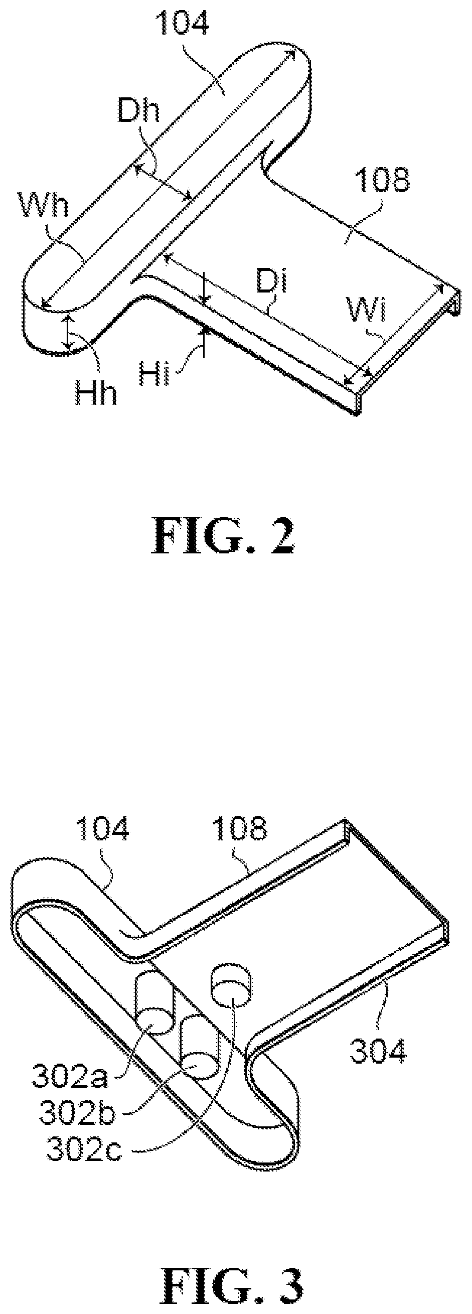
[0016] FIG. 2 shows a top view of a vent head having an inlet;
[0017] FIG. 3 shows a bottom view of the vent head having the inlet;
[0018] FIG. 4 shows a toilet bowl with both toilet seat and toilet lid in an up position;
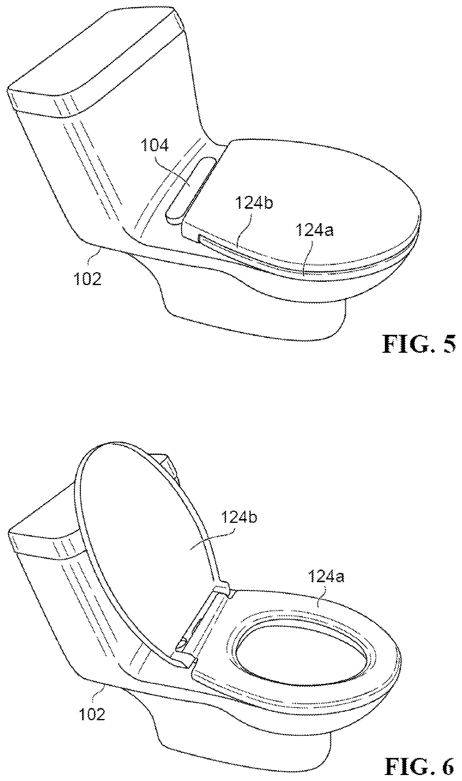
[0019] FIG. 5 shows a toilet bowl with both toilet seat and toilet lid in a down position;
[0020] FIG. 6 shows a toilet bowl with a toilet seat in a down position and a toilet lid in an up position.
DETAILED DESCRIPTION OF THE PREFERRED EMBODIMENTS
[0021] The following descriptions describe the preferred embodiments of the invention by way of example only.
[0022] FIG. 1 shows an exploded view of an odour free toilet system 100. A toilet bowl 102 has a top surface defining a pair of mounting holes 122a, 122b for mounting a toilet seat 124a and a toilet lid 124b. A plate 106 made of a ferromagnetic material such as iron, nickel and cobalt, is adhesively secured to the top surface of the toilet bowl 102 in between the pair of mounting holes 122a, 122b. A vent head 104 having an inlet 108 further comprising at least one magnet is magnetically attached to the plate 106 as will be further explained in the hereinafter. The top surface of toilet bowl 102 further defines an outlet hole 110 for receiving an outlet fitting 112. An outlet hose 114 has on one end an outlet hose fitting 114a and on the other end an outlet hose fitting 114b. The outlet hose fitting 114a matches the outlet fitting 112 at the bottom end thereof, thereby securing the outlet fitting 112 in the outlet hole 110. The outlet hose fitting 114b matches a fitting 118 of a pipe 116 connected to a suction fan 120 such as a common TT 100 vent having an input rating of about 187 cubic meter per hour (about 110 cubic feet per minute) mounted in a bathroom ceiling. The fitting 118 can be a wall fitting, the pipe 116 can be concealed partly in the bathroom wall and partly in the bathroom wall ceiling. The vent head 104 covers the outlet fitting 112 so that inlet 108 provides air suction to the toilet bowl 102 for disposal of toilet odours out of a roof vent (not shown).
[0023] Advantageously, air suction is provided close to the source of toilet odours.
[0024] Preferably, the vent head 104 having the inlet 108 forms a substantially symmetrical T-shape so that the outlet hole 110 and the outlet fitting 112 can be placed on either side of the toilet bowl 102.
[0025] Preferably, the plate 106 has a thickness ranging from about 1/16 of an inch (1.5 mm) to about 1/8 of an inch (3 mm).
[0026] FIG. 2 shows a top view of the vent head 104 having the inlet 108.
[0027] Preferably, the vent head 104 having the inlet 108 is made of a polymeric material.
[0028] The vent head 104 has a width Wh, a depth Dh, and a height Hh. The inlet 108 has a width Wi, a depth Di, and a height Hi.
[0029] Preferably, the vent head 104 has the width Wh of about 190 mm (7.5 inches), the depth Dh of about 39 mm (1.5 inches) and the height Hh of about 18 mm (0.7 inches).
[0030] Preferably, the inlet 108 has the width Wi of about 86 mm (3.4 inches), the depth Di of about 72 mm (2.8 inches), and the height Hi of about 9 mm (0.35 inches).
[0031] FIG. 3 shows a bottom view of the vent head 104 having the inlet 108. At least one magnet is required to attach the vent head 104 having the inlet 108 to the plate 106. Shown are three magnets 302a, 302b, 302c secured to the vent head 104 having the inlet 108.
[0032] Advantageously, the vent head 104 having the inlet 108 can be manually removed without tools for cleaning purposes.
[0033] Preferably, the vent head 104 having the inlet 108 further comprises a bottom gasket 304 for sealingly engaging the bottom of the vent head 104 having the inlet 108 to the top surface in the rear of the toilet bowl 102 when the vent head 104 having the inlet 108 is magnetically attached to the plate 106.
[0034] Preferably the bottom gasket 304 is made of a soft polymeric material.
[0035] FIG. 4 shows the toilet bowl 102 with both toilet seat 124a and toilet lid 124b in an up position. The inlet 108 fits under the toilet seat 124a and the toilet lid 124b between the mounting assemblies 402a, 402b of the toilet seat 124a and the toilet lid 124b. The vent head 104 is hidden from view behind the toilet seat 124a and the toilet lid 124b. The inlet 108 is set back a predetermined distance D from the rim 404 of the toilet bowl 102.
[0036] Preferably, the predetermined distance D ranges from about 15 mm (0.6 inches to about 25 mm (1 inch).
[0037] FIG. 5 shows the toilet bowl 102 with both toilet seat 124a and toilet lid 124b in a down position. The vent head 104 is rearwardly of the toilet seat 124a and the toilet lid 124b. The inlet 108 is hidden from view under the toilet seat 124a and the toilet lid 124b.
[0038] FIG. 6 shows the toilet bowl 102 with the toilet seat 124a in a down position and the toilet lid 124b in an up position. Both the vent head 104 and the inlet 108 are hidden from view, the toilet seat 124a in the down position hides the inlet 108 from view and the toilet lid 124b in the up position hides the vent head 104 from view.
[0039] The vent head 104 having the inlet 108 is out of the way of the toilet seat 124a and the toilet lid 124b in any position of the toilet seat 124a and the toilet lid 124b.
[0040] Advantageously, the vent head 104 having the inlet 108 are unobtrusive in actual use, hidden from view in most positions of the toilet seat 124a and the toilet lid 124b.
[0041] Preferably, the outlet fitting 112, the outlet hose 114, the outlet hose fittings 114a, 114b, the pipe 116, the fitting 118, and the side inlet 706 are 1 inch (25.4 mm) plumbing parts.
[0042] Advantageously, the odour free toilet system 100 allows for any hazardous electrical items to be placed remotely from a user of the odour free toilet system 100.
[0043] A person skilled in the art will have by now appreciated the full scope of the invention. In particular, the scope of the invention is not limited to the preferred embodiments described by way of example in the above.
* * * * *
D00000
D00001
D00002
D00003
D00004
XML
uspto.report is an independent third-party trademark research tool that is not affiliated, endorsed, or sponsored by the United States Patent and Trademark Office (USPTO) or any other governmental organization. The information provided by uspto.report is based on publicly available data at the time of writing and is intended for informational purposes only.
While we strive to provide accurate and up-to-date information, we do not guarantee the accuracy, completeness, reliability, or suitability of the information displayed on this site. The use of this site is at your own risk. Any reliance you place on such information is therefore strictly at your own risk.
All official trademark data, including owner information, should be verified by visiting the official USPTO website at www.uspto.gov. This site is not intended to replace professional legal advice and should not be used as a substitute for consulting with a legal professional who is knowledgeable about trademark law.