Sheet Manufacturing Apparatus, Sheet, And Sheet Manufacturing Method
HIGUCHI; Naotaka
U.S. patent application number 16/495920 was filed with the patent office on 2020-04-30 for sheet manufacturing apparatus, sheet, and sheet manufacturing method. The applicant listed for this patent is SEIKO EPSON CORPORATION. Invention is credited to Naotaka HIGUCHI.
| Application Number | 20200131705 16/495920 |
| Document ID | / |
| Family ID | 63585386 |
| Filed Date | 2020-04-30 |


View All Diagrams
| United States Patent Application | 20200131705 |
| Kind Code | A1 |
| HIGUCHI; Naotaka | April 30, 2020 |
SHEET MANUFACTURING APPARATUS, SHEET, AND SHEET MANUFACTURING METHOD
Abstract
A sheet manufacturing apparatus includes a drum unit having a plurality of openings, a web forming unit that has a deposition surface, on which material containing fibers that has passed through the openings is deposited, and forms a second web on the deposition surface, a sheet forming unit that processes the second web and forms a sheet, and a control unit that controls a basis weight of the second web deposited on the deposition surface in a direction crossing a transport direction of the second web.
| Inventors: | HIGUCHI; Naotaka; (Suwa-gun, Fujimi-machi, Nagano, JP) | ||||||||||
| Applicant: |
|
||||||||||
|---|---|---|---|---|---|---|---|---|---|---|---|
| Family ID: | 63585386 | ||||||||||
| Appl. No.: | 16/495920 | ||||||||||
| Filed: | March 13, 2018 | ||||||||||
| PCT Filed: | March 13, 2018 | ||||||||||
| PCT NO: | PCT/JP2018/009668 | ||||||||||
| 371 Date: | September 20, 2019 |
| Current U.S. Class: | 1/1 |
| Current CPC Class: | D21F 1/74 20130101; D21F 7/06 20130101; D21F 2/00 20130101; D21G 9/0027 20130101; D21F 1/48 20130101 |
| International Class: | D21F 1/74 20060101 D21F001/74; D21F 2/00 20060101 D21F002/00; D21G 9/00 20060101 D21G009/00; D21F 1/48 20060101 D21F001/48; D21F 7/06 20060101 D21F007/06 |
Foreign Application Data
| Date | Code | Application Number |
|---|---|---|
| Mar 22, 2017 | JP | 2017-055337 |
Claims
1. A sheet manufacturing apparatus comprising: a sieving unit having a plurality of openings; a web forming unit that has a deposition surface on which material containing fibers that has passed through the openings is deposited and forms a web on the deposition surface; a sheet forming unit that forms a sheet by processing the web; and a control unit that controls a basis weight of the web deposited on the deposition surface in a direction crossing a transport direction of the web.
2. The sheet manufacturing apparatus according to claim 1, wherein the sieving unit includes a rotatable drum unit, a material supply pipe that supplies a transport air flow containing the material to inside of the drum unit is arranged, and the material supply pipe includes a first supply pipe, a second supply pipe that branches from the first supply pipe at a branch portion and is connected to one end in a rotation axis direction of the drum unit, a third supply pipe that branches from the first supply pipe at the branch portion and is connected to the other end in the rotation axis direction of the drum unit, and a first adjustment unit that is provided near the branch portion and changes a ratio between a transport amount of the material transported by the transport air flow flowing through the second supply pipe and a transport amount of the material transported by the transport air flow flowing through the third supply pipe under control of the control unit.
3. The sheet manufacturing apparatus according to claim 1, wherein the sieving unit includes a rotatable drum unit, a housing portion that covers at least a portion including the openings of the drum unit, a material supply port that supplies the transport air flow containing the material to inside of the drum unit, first and second air intake ports which supply air containing no material from outside of the housing portion to inside of the drum unit and which are provided away from each other in a rotation axis direction of the drum unit, and a second adjustment unit that changes a ratio of flow rates of air supplied from the first and the second air intake ports under control of the control unit.
4. The sheet manufacturing apparatus according to claim 1, wherein the sieving unit includes a rotatable drum unit, a housing portion that covers at least a portion including the openings of the drum unit, a material supply port that supplies the transport air flow containing the material to inside of the drum unit, first and second air intake ports which supply air containing no material from outside of the housing portion to inside of the drum unit and which are provided away from each other in a rotation axis direction of the drum unit, and a position change unit that changes a position of the first air intake port with respect to the material supply port and a position of the second air intake port with respect to the material supply port under control of the control unit.
5. The sheet manufacturing apparatus according to claim 1, wherein the control unit controls a flow rate of the transport air flow.
6. The sheet manufacturing apparatus according to claim 1, further comprising: a suction unit that sucks the material to the deposition surface by a suction air flow, wherein the control unit controls a flow rate of the suction air flow.
7. A sheet manufacturing apparatus comprising: a web forming unit that forms a web by depositing a material containing fibers on a deposition surface; a sheet forming unit that forms a sheet by processing the web; a receiving unit that receives a setting of a basis weight distribution of the sheet; and a control unit that controls a basis weight of the web to be deposited on the deposition surface of the web forming unit based on the basis weight distribution received by the receiving unit.
8. The sheet manufacturing apparatus according to claim 7, further comprising: a sieving unit where a plurality of openings are formed, wherein the material that passes through the openings of the sieving unit is deposited on the deposition surface, and the receiving unit receives a basis weight distribution in a predetermined direction crossing a transport direction of the web as a basis weight distribution of the sheet.
9. The sheet manufacturing apparatus according to claim 7, further comprising: a detection unit that detects a thickness or a basis weight of the web or the sheet, wherein the control unit controls a basis weight distribution of the web in a predetermined direction crossing a transport direction of the web based on a detection result of the detection unit.
10. A sheet that is transported by being pinched by a transport roller pair, wherein variation is provided in a basis weight distribution in a predetermined direction crossing a transport direction and a basis weight in a central portion is greater than a basis weight in an end portion in the predetermined direction.
11. The sheet according to claim 10, wherein a thickness of the end portion in the predetermined direction is equal to a thickness of the central portion.
12. A sheet manufactured by the sheet manufacturing apparatus according to claim 1.
13. A sheet manufacturing method comprising: a first step of forming a web by depositing a material containing fibers on a deposition surface; a second step of transporting the web; and a third step of forming a sheet by processing the transported web, wherein, in the first step, variation is generated in a basis weight distribution in a predetermined direction crossing a transport direction of the web and a basis weight in a central portion is made greater than a basis weight in an end portion in the predetermined direction.
14. A sheet manufactured by the sheet manufacturing apparatus according to claim 7.
Description
CROSS-REFERENCE TO RELATED APPLICATIONS
[0001] This application is a U.S. National stage application of International Patent Application No. PCT/JP2018/009668, filed on Mar. 13, 2018, which claims priority under 35 U.S.C. .sctn. 119(a) to Japanese Patent Application No. 2017-055337, filed in Japan on Mar. 22, 2017. The entire disclosure of Japanese Patent Application No. 2017-055337 is hereby incorporated herein by reference.
TECHNICAL FIELD
[0002] The present invention relates to a sheet manufacturing apparatus, a sheet, and a sheet manufacturing method.
BACKGROUND ART
[0003] Conventionally, a method of controlling a paper thickness in a step of manufacturing paper is known (for example, see Japanese Unexamined Patent Application Publication No. 8-13376). In a papermaking process in which base paper that is solid-liquid separated from white water containing pulp component is pressed and dried and thereafter wound up, an apparatus described in Japanese Unexamined Patent Application Publication No. 8-13376 controls a basis weight so that a deviation from a set paper thickness becomes small based on a paper thickness measurement value before the paper is wound up.
[0004] As described in Japanese Unexamined Patent Application Publication No. 8-13376, when a paper or a sheet such as a paper is manufactured, it is preferable that the basis weight is uniform. Therefore, there has been no proposal to provide variation in distribution of basis weight within a surface of a sheet.
SUMMARY
[0005] An object of the present invention is to appropriately control the distribution of basis weight in a sheet when manufacturing the sheet.
[0006] To solve the above problem, the sheet manufacturing apparatus of the present invention includes a sieving unit having a plurality of openings, a web forming unit that has a deposition surface on which material containing fibers that has passed through the openings is deposited and forms a web on the deposition surface, a sheet forming unit that forms a sheet by processing the web, and a control unit that controls a basis weight of the web deposited on the deposition surface in a direction crossing a transport direction of the web.
[0007] According to the present invention, in the sheet manufacturing apparatus that manufacture a sheet by depositing a material containing fibers, a distribution of basis weight of a sheet to be manufactured can be controlled by controlling the basis weight of a web to be deposited. Thereby, it is possible to realize a desired basis weight distribution in the sheet. For example, by making the basis weight in a central portion greater than that in end portions in a predetermined direction within a surface of the sheet, it is possible to manufacture a sheet whose rigidity in the predetermined direction is high and whose transportability is high when being transported by a printer or the like.
[0008] In the above configuration, the sheet manufacturing apparatus may have a configuration in which the sieving unit includes a rotatable drum unit, a material supply pipe that supplies a transport air flow containing the material to inside of the drum unit is arranged, and the material supply pipe includes a first supply pipe, a second supply pipe that branches from the first supply pipe at a branch portion and is connected to one end in a rotation axis direction of the drum unit, a third supply pipe that branches from the first supply pipe at the branch portion and is connected to the other end in the rotation axis direction of the drum unit, and a first adjustment unit that is provided near the branch portion and changes a ratio between a transport amount of the material transported by the transport air flow flowing through the second supply pipe and a transport amount of the material transported by the transport air flow flowing through the third supply pipe under control of the control unit.
[0009] According to this configuration, it is possible to change the ratio of materials supplied to the drum unit by changing the ratio between the transport amount of the material transported by the transport air flow from one side and the transport amount of the material transported by the transport air flow from the other side for the drum unit. Therefore, the basis weight distribution of the sheet to be manufactured can be controlled by changing the distribution of the material deposited through the openings of the sieving unit.
[0010] In the above configuration, the sheet manufacturing apparatus may have a configuration in which the sieving unit includes a rotatable drum unit, a housing portion that covers at least a portion including the openings of the drum unit, a material supply port that supplies the transport air flow containing the material to inside of the drum unit, first and second air intake ports which supply air containing no material from outside of the housing portion to inside of the drum unit and which are provided away from each other in a rotation axis direction of the drum unit, and a second adjustment unit that changes a ratio of flow rates of air supplied from the first and the second air intake ports under control of the control unit.
[0011] According to this configuration, the distribution of air flow flowing out from the drum unit can be changed by changing the ratio between air flows flowing into the drum unit. Therefore, the basis weight distribution of the sheet to be manufactured can be controlled by changing the distribution of the material deposited through the openings of the sieving unit.
[0012] In the above configuration, the sheet manufacturing apparatus may have a configuration in which the sieving unit includes a rotatable drum unit, a housing portion that covers at least a portion including the openings of the drum unit, a material supply port that supplies the transport air flow containing the material to inside of the drum unit, first and second air intake ports which supply air containing no material from outside of the housing portion to inside of the drum unit and which are provided away from each other in a rotation axis direction of the drum unit, and a position change unit that changes a position of the first air intake port with respect to the material supply port and a position of the second air intake port with respect to the material supply port under control of the control unit.
[0013] According to this configuration, the distribution of air flow flowing out from the drum unit can be changed by changing the distribution of air flows flowing into the drum unit. Therefore, the basis weight distribution of the sheet to be manufactured can be controlled by changing the distribution of the material deposited through the openings of the sieving unit.
[0014] In the above configuration, the sheet manufacturing apparatus may have a configuration in which the control unit controls a flow rate of the transport air flow.
[0015] According to this configuration, the distribution of the deposited material can be more effectively controlled by controlling the flow rate of the transport air flow supplied to the drum unit.
[0016] In the above configuration, the sheet manufacturing apparatus may have a configuration in which a suction unit that sucks the material to the deposition surface by a suction air flow is further included and the control unit controls a flow rate of the suction air flow.
[0017] According to this configuration, the distribution of the deposited material can be more effectively controlled by controlling the flow rate of the suction air flow that sucks the material to the deposition surface.
[0018] To solve the above problem, the sheet manufacturing apparatus of the present invention includes a web forming unit that forms a web by depositing a material containing fibers on a deposition surface, a sheet forming unit that forms a sheet by processing the web, a receiving unit that receives a setting of a basis weight distribution of the sheet, and a control unit that controls a basis weight of the web to be deposited on the deposition surface of the web forming unit based on the basis weight distribution received by the receiving unit.
[0019] According to the present invention, when manufacturing a sheet by depositing a material containing fibers, it is possible to manufacture a sheet of a set basis weight by controlling the basis weight of the web according to a setting of the basis weight of the sheet. Thereby, it is possible to realize a desired basis weight distribution in the sheet. For example, by making the basis weight in a central portion greater than that in end portions in a predetermined direction within a surface of the sheet, it is possible to manufacture a sheet whose rigidity in the predetermined direction is high and whose transportability is high when being transported by a printer or the like.
[0020] In the above configuration, the sheet manufacturing apparatus may have a configuration in which a sieving unit where a plurality of openings are formed is further included, the material that passes through the openings of the sieving unit is deposited on the deposition surface, and the receiving unit receives a basis weight distribution in a predetermined direction crossing a transport direction of the web as a basis weight distribution of the sheet.
[0021] According to this configuration, when the basis weight distribution in a predetermined direction crossing the transport direction of the web is set, it is possible to manufacture a sheet having the set basis weight distribution by controlling the basis weight distribution of the web according to the setting.
[0022] In the above configuration, the sheet manufacturing apparatus may have a configuration in which a detection unit that detects a thickness or a basis weight of the web or the sheet is further included and the control unit controls a basis weight distribution of the web in a predetermined direction crossing a transport direction of the web based on a detection result of the detection unit.
[0023] According to this configuration, it is possible to more appropriately control the basis weight distribution of the web by detecting the thickness of the web or the sheet.
[0024] To solve the above problem, the sheet of the present invention is a sheet which is transported by being pinched by a transport roller pair and in which variation is provided in a basis weight distribution in a predetermined direction crossing a transport direction and a basis weight in a central portion is greater than a basis weight in an end portion in the predetermined direction.
[0025] According to the present invention, it is possible to realize a sheet which is rigid in the transport direction and excellent in transportability when being transported by the roller pair as compared with a sheet where the basis weight is substantially uniform in the entire sheet.
[0026] In the above configuration, the sheet may have a configuration in which a thickness of the end portion in the predetermined direction is equal to a thickness of the central portion.
[0027] According to this configuration, it is possible to realize a sheet that is excellent in rigidity in the transport direction and transportability due to the basis weight distribution and has no unevenness in thickness.
[0028] To solve the above problem, the sheet of the present invention is a sheet manufactured by one of the sheet manufacturing apparatuses described above.
[0029] According to the present invention, it is possible to easily obtain a sheet whose rigidity in the transport direction, transportability, and the like when being transported by the roller pair are brought into a desired state.
[0030] To solve the above problem, the sheet manufacturing method of the present invention includes a first step of forming a web by depositing a material containing fibers on a deposition surface, a second step of transporting the web, and a third step of forming a sheet by processing the transported web, and generates variation in a basis weight distribution in a predetermined direction crossing a transport direction of the web to make a basis weight in a central portion greater than a basis weight in an end portion in the predetermined direction in the first step.
[0031] According to the present invention, it is possible to manufacture a sheet by depositing a material containing fibers and control the basis weight distribution of the sheet to be manufactured. Thereby, it is possible to realize a sheet which is rigid in the transport direction and excellent in transportability when being transported by a roller pair as compared with a sheet where the basis weight is substantially uniform in the entire sheet.
BRIEF DESCRIPTION OF DRAWINGS
[0032] FIG. 1 is a schematic diagram showing a configuration of a sheet manufacturing apparatus according to a first embodiment.
[0033] FIG. 2 is an appearance perspective view of the sheet manufacturing apparatus.
[0034] FIG. 3 is a main portion perspective view of the sheet manufacturing apparatus.
[0035] FIG. 4 is a main portion cross-sectional view of the sheet manufacturing apparatus.
[0036] FIG. 5 is a main portion enlarged view of the sheet manufacturing apparatus.
[0037] FIG. 6 is a cross-sectional view taken along line A-A in FIG. 5.
[0038] FIG. 7 is an explanatory diagram showing detection of basis weight by the sheet manufacturing apparatus and is a plan view showing an arrangement state of a thickness sensor.
[0039] FIG. 8 is an explanatory diagram showing detection of basis weight by the sheet manufacturing apparatus and is a graphic chart showing a distribution of basis weight of a second web.
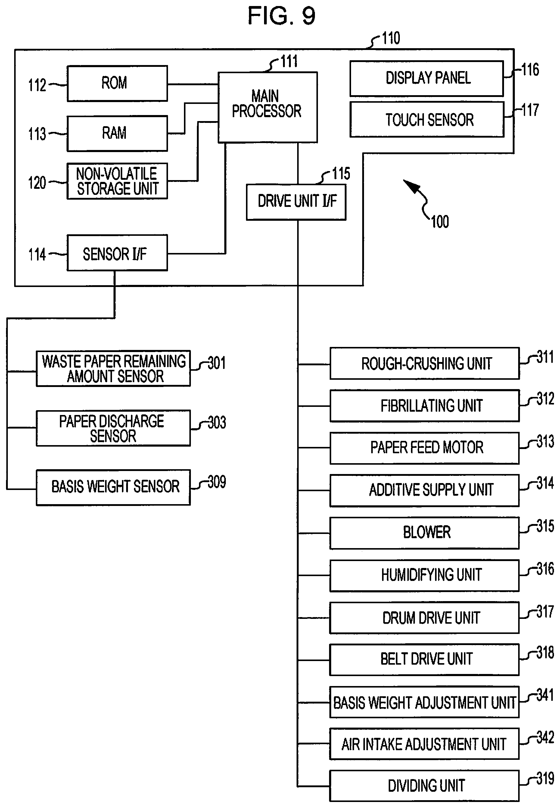
[0040] FIG. 9 is a block diagram showing a configuration of a control system of the sheet manufacturing apparatus.
[0041] FIG. 10 is a block diagram showing a functional configuration of a control unit and a storage unit.
[0042] FIG. 11 is a flowchart showing an operation of the sheet manufacturing apparatus.
[0043] FIG. 12 is a diagram showing a display example of the sheet manufacturing apparatus.
[0044] FIG. 13 is a main portion enlarged view of a sheet manufacturing apparatus according to a second embodiment.
[0045] FIG. 14 is a main portion perspective view of a sheet manufacturing apparatus according to a third embodiment.
[0046] FIG. 15 is a main portion disassembled perspective view of a sheet manufacturing apparatus according to a fourth embodiment.
[0047] FIG. 16 is a diagram showing a first air intake position of an air intake port of the sheet manufacturing apparatus according to the fourth embodiment.
[0048] FIG. 17 is a diagram showing a second air intake position of the air intake port of the sheet manufacturing apparatus according to the fourth embodiment.
[0049] FIG. 18 is a diagram showing a third air intake position of the air intake port of the sheet manufacturing apparatus according to the fourth embodiment.
[0050] FIG. 19 is a diagram showing a fourth air intake position of the air intake port of the sheet manufacturing apparatus according to the fourth embodiment.
[0051] FIG. 20 is a graphic chart showing a basis weight distribution of a sheet manufactured by the sheet manufacturing apparatus according to the fourth embodiment.
DESCRIPTION OF EMBODIMENTS
[0052] Hereinafter, preferred embodiments of the present invention will be described in detail with reference to the drawings. The embodiments described below do not limit the subject matter of the present invention described in the claims. All of the components described below are not necessarily essential components of the present invention.
First Embodiment
[0053] FIG. 1 is a schematic diagram showing a configuration of a sheet manufacturing apparatus 100 according to a first embodiment to which the present invention is applied.
[0054] The sheet manufacturing apparatus 100 described in the present embodiment is, for example, an apparatus suitable for manufacturing new paper by dry-fibrillating and fiberizing used waste paper such as confidential paper used as raw material and thereafter pressurizing, heating, and cutting the fiberized paper. Bond strength and/or whiteness of a paper product may be improved, and functions such as color, aroma, and flame retardancy may be added, according to uses, by mixing various additives to a fiberized raw material. Further, it is possible to manufacture papers of various thickness and sizes such as regular size office papers of A4 and A3 and a name card paper according to uses by forming the paper while controlling density, thickness, and shape of the paper.
[0055] The sheet manufacturing apparatus 100 includes a supply unit 10, a rough-crushing unit 12, a fibrillating unit 20, a selection unit 40, a first web forming unit 45, a rotating body 49, a mixing unit 50, a depositing unit 60, a second web forming unit 70, a transport unit 79, a sheet forming unit 80, and a cutting unit 90.
[0056] Further, the sheet manufacturing apparatus 100 includes humidifying units 202, 204, 206, 208, 210, and 212 in order to humidify a raw material and/or a space where the raw material moves. Specific configurations of the humidifying units 202, 204, 206, 208, 210, and 212 are optional, and examples of the configurations include a steam type, a vaporizing type, a hot air vaporizing type, and an ultrasonic type.
[0057] In the present embodiment, the humidifying units 202, 204, 206, and 208 are composed of a vaporizing type or a hot air vaporizing type humidifier. Specifically, the humidifying units 202, 204, 206, and 208 have a filter infiltrated with water (not shown in the drawings) and supplies humidified air whose humidity is increased by causing air to pass through the filter. The humidifying units 202, 204, 206, and 208 may have a heater (not shown in the drawings) that effectively increases humidity of the humidified air.
[0058] In the present embodiment, the humidifying unit 210 and the humidifying unit 212 are composed of an ultrasonic type humidifier. Specifically, the humidifying units 210 and 212 have a vibration unit (not shown in the drawings) that atomizes water, and supplies mist generated by the vibration unit.
[0059] The supply unit 10 supplies raw material to the rough-crushing unit 12. Raw material where the sheet manufacturing apparatus 100 manufactures a sheet may be a material containing fibers, and examples of the raw material include paper, pulp, pulp sheet, cloth including nonwoven fabric, and fabric. In the present embodiment, a configuration where the sheet manufacturing apparatus 100 uses waste papers as raw material is illustrated. For example, the supply unit 10 may have a configuration including a stacker that piles up and accumulates waste papers and an automatic feeding apparatus that feeds out waste papers from the stacker to the rough-crushing unit 12.
[0060] The rough-crushing unit 12 cuts (roughly crushes) the raw material supplied from the supply unit 10 into roughly crushed pieces by using rough-crushing blades 14. The rough-crushing blades 14 cut the raw material in a gas such as in the atmosphere (in the air). The rough-crushing unit 12 includes, for example, the pair of rough-crushing blades 14 that pinch and cut the raw material and a drive unit that rotates the rough-crushing blades 14, so that the rough-crushing unit 12 can have a configuration similar to that of a shredder. The shape and the size of the roughly crushed pieces are optional, and may be suitable for fibrillation processing in the fibrillating unit 20. For example, the rough-crushing unit 12 cuts the raw material into paper pieces having sizes of one to several cm square or less.
[0061] The rough-crushing unit 12 has a chute (hopper) 9 that receives roughly crushed pieces that are cut and dropped by the rough-crushing blades 14. The chute 9 has, for example, a tapered shape whose width gradually decreases in a direction in which the roughly crushed pieces flow (proceed). Therefore, the chute 9 can receive many roughly crushed pieces. The chute 9 is connected with a pipe 2 communicating with the fibrillating unit 20. The pipe 2 forms a transport path for causing the fibrillating unit 20 to transport the raw material (roughly crushed pieces) cut by the rough-crushing blades 14. The roughly crushed pieces are gathered by the chute 9 and transferred (transported) to the fibrillating unit 20 through the pipe 2.
[0062] Humidified air is supplied by the humidifying unit 202 to the chute 9 included in the rough-crushing unit 12 or a vicinity of the chute 9. Thereby, it is possible to suppress a phenomenon in which the roughly crushed pieces cut by the rough-crushing blades 14 are adsorbed to inner surfaces of the chute 9 and/or the pipe 2 by static electricity. Further, the roughly crushed pieces cut by the rough-crushing blades 14 are transferred to the fibrillating unit 20 along with humidified air (of high humidity), so that it is possible to expect an effect of suppressing adhesion of a fibrillated matter inside the fibrillating unit 20. The humidifying unit 202 may be configured to supply humidified air to the rough-crushing blades 14 and eliminate electricity from the raw material supplied from the supply unit 10. The electricity may be eliminated by using an ionizer along with the humidifying unit 202.
[0063] The fibrillating unit 20 fibrillates the roughly crushed pieces cut by the rough-crushing unit 12. More specifically, the fibrillating unit 20 performs fibrillation processing on the raw material (roughly crushed pieces) cut by the rough-crushing unit 12 and generates a fibrillated matter. Here, "to fibrillate" means to untangle a raw material (material to be fibrillated), where a plurality of fibers are bound together, into fibers separated from each other. The fibrillating unit 20 also has a function to separate substances such as resin particles, ink, toner, and blot inhibitor, which are attached to the raw material, from the fibers.
[0064] A matter that has passed through the fibrillating unit 20 is called a "fibrillated matter". The "fibrillated matter" may include resin particles separated from fibers when the fibers are untangled (resin particles for binding a plurality of fibers together), a color material such as ink or toner, and additive agents such as a blot inhibitor and a paper strengthening agent, in addition to the untangled fibrillated fibers. An untangled fibrillated matter has a string shape or a ribbon shape. An untangled fibrillated matter may exist in a state (an independent state) of not being intertwined with other untangled fibers, or may exist in a state where an untangled fibrillated matter is tangled with other untangled fibrillated matter and forms a lump shape (a state where a so-called "agglomerate" is formed).
[0065] The fibrillating unit 20 performs dry-type fibrillation. Here, fibrillation performed in a gas such as in the atmosphere (in the air) instead of in liquid is referred to as dry-type fibrillation. In the present embodiment, the fibrillating unit 20 uses an impeller mill. Specifically, the fibrillating unit 20 includes a rotor (not shown in the drawings) rotating at high speed and a liner (not shown in the drawings) located on an outer circumference of the rotor. The roughly crushed pieces of the raw material cut by the rough-crushing unit 12 are sandwiched between the rotor and the liner of the fibrillating unit 20 and fibrillated. The fibrillating unit 20 generates an air flow by rotation of the rotor. By this air flow, the fibrillating unit 20 can suck the roughly crushed pieces, which are raw material, from the pipe 2 and transport the fibrillated matter to a discharge port 24. The fibrillated matter is sent out from the discharge port 24 to the pipe 3 and transferred to the selection unit 40 through the pipe 3.
[0066] In this way, the fibrillated matter generated in the fibrillating unit 20 is transported from the fibrillating unit 20 to the selection unit 40 by the air flow generated by the fibrillating unit 20. Further, in the present embodiment, the sheet manufacturing apparatus 100 includes a fibrillating unit blower 26, which is an air flow generating apparatus, and the fibrillated matter is transported to the selection unit 40 by the air flow generated by the fibrillating unit blower 26. The fibrillating unit blower 26 is attached to the pipe 3. The fibrillating unit blower 26 sucks air along with the fibrillated matter from the fibrillating unit 20 and feeds the air to the selection unit 40.
[0067] The selection unit 40 has an introduction port 42 through which the fibrillated matter fibrillated by the fibrillating unit 20 flows in along with the air flow from the pipe 3. The selection unit 40 selects the fibrillated matter introduced to the introduction port 42 according to the lengths of fibers. Specifically, regarding the fibrillated matter fibrillated by the fibrillating unit 20, the selection unit 40 selects fibrillated matter whose size is smaller than or equal to a predetermined size as a first selected matter, and selects fibrillated matter whose size is greater than the first selected matter as a second selected matter. The first selected matter includes fibers, particles, or the like, and the second selected matter includes, for example, large fibers, unfibrillated pieces (roughly crushed pieces that are not sufficiently fibrillated), agglomerates where fibrillated fibers clump together or intertwined with each other, and the like.
[0068] In the present embodiment, the selection unit 40 has a drum unit (sieving unit) 41 and a housing portion 43 that houses the drum unit 41.
[0069] The drum unit 41 is a cylindrical sieving unit rotationally driven by a motor. The drum unit 41 has a net (filter, screen) and functions as a sieving unit. By meshes of the net, the drum unit 41 selects the first selected matter that is smaller than the size of the mesh (opening) of the net and the second selected matter that is greater than the size of the mesh (opening) of the net. As the net of the drum unit 41, it is possible to use, for example, a metal net, an expanded metal made by expanding a metal plate having cut lines, and a punching metal made by forming holes in a metal plate by a pressing machine or the like.
[0070] The fibrillated matter introduced to the introduction port 42 is sent inside the drum unit 41 along with the air flow, and the first selected matter falls downward from the meshes of the net of the drum unit 41 by the rotation of the drum unit 41. The second selected matter that cannot pass through the meshes of the net of the drum unit 41 is introduced to a discharge port 44 by being flown by the air flow flown from the introduction port 42 to the drum unit 41 and sent out to a pipe 8.
[0071] The pipe 8 connects the inside of the drum unit 41 with the pipe 2. The second selected matter flown through the pipe 8 flows through the pipe 2 along with the roughly crushed pieces cut by the rough-crushing unit 12 and is introduced to an introduction port 22 of the fibrillating unit 20. Thereby, the second selected matter is returned to the fibrillating unit 20 and subjected to the fibrillation processing.
[0072] The first selected matter selected by the drum unit 41 is dispersed to the air through the meshes of the net of the drum unit 41, and falls toward a mesh belt 46 of the first web forming unit 45 located below the drum unit 41.
[0073] The first web forming unit 45 (separation unit) includes the mesh belt 46 (separation belt), rollers 47, and a suction unit (suction mechanism) 48. The mesh belt 46 is an endless-shaped belt. The mesh belt 46 is suspended by three rollers 47 and transported in a direction indicated by an arrow shown in FIG. 1 by movement of the rollers 47. A surface of the mesh belt 46 is formed of a net where openings of a predetermined size are arranged. In the first selected matter falling from the selection unit 40, microparticles having a size that can pass through the meshes of the net fall below the mesh belt 46 and fibers having a size that cannot pass through the meshes of the net are deposited on the mesh belt 46 and transported in the arrow V1 direction along with the mesh belt 46. The microparticles that fall from the mesh belt 46 includes fibrillated matter whose size is relatively small or whose density is low (resin particles, color materials, additive agents, and the like), and the microparticles are matter to be eliminated, which is not used by the sheet manufacturing apparatus 100 to manufacture a sheet S.
[0074] The mesh belt 46 moves at a constant velocity V1 during a normal operation in which the sheet S is manufactured. The velocity V1 is a preset constant velocity and is controlled by a control unit 150 (FIG. 10) described later. The velocity V1 at which the mesh belt 46 moves can be regarded as a transport velocity at which the mesh belt 46 transports a first web W1, that is, a transport velocity of the first web W1 in the selection unit 40.
[0075] Here, "during a normal operation" is "during an operation other than starting control and stopping control of the sheet manufacturing apparatus 100 described later", and more specifically is "during a period in which the sheet manufacturing apparatus 100 manufactures a sheet S of a desired quality".
[0076] Therefore, the fibrillated matter subjected to the fibrillation processing in the fibrillating unit 20 is selected into the first selected matter and the second selected matter by the selection unit 40, and the second selected matter is returned to the fibrillating unit 20. Further, the matter to be eliminated is eliminated from the first selected matter by the first web forming unit 45. The first selected matter other than the matter to be eliminated is a material suited to manufacturing of the sheet S, and the material is deposited on the mesh belt 46 and forms a first web W1.
[0077] The suction unit 48 sucks air from below the mesh belt 46. The suction unit 48 is connected to a dust collection unit 27 (a dust collection apparatus) through a pipe 23. The dust collection unit 27 is a filter type or a cyclone type dust collection apparatus. The dust collection unit 27 separates microparticles from air flow. A collection blower 28 is installed in the downstream of the dust collection unit 27. The collection blower 28 functions as a dust collection suction unit that sucks air from the dust collection unit 27. Air discharged from the collection blower 28 is discharged to the outside of the sheet manufacturing apparatus 100 through a pipe 29.
[0078] In this configuration, air is sucked from the suction unit 48 through the dust collection unit 27 by the collection blower 28. In the suction unit 48, microparticles passing through the meshes of the net of the mesh belt 46 are sucked along with air and sent to the dust collection unit 27 through the pipe 23. The dust collection unit 27 separates the microparticles that have passed through the mesh belt 46 from the air flow and accumulates the microparticles.
[0079] Therefore, fibers obtained by eliminating the matter to be eliminated from the first selected matter are deposited and the first web W1 is formed on the mesh belt 46. The collection blower 28 performs suction, so that formation of the first web W1 on the mesh belt 46 is promoted and the matter to be eliminated is quickly eliminated.
[0080] The humidifying unit 204 supplies humidified air to a space including the drum unit 41. The humidified air humidifies the first selected matter inside the selection unit 40. Thereby, adhesion of the first selected matter to the mesh belt 46 by an electrostatic force is weakened, so that the first selected matter can be easily peeled off from the mesh belt 46. Further, it is possible to prevent the first selected matter from being adhered to the rotating body 49 and an inner wall of the housing portion 43 by an electrostatic force. Further, the matter to be eliminated can be efficiently sucked by the suction unit 48.
[0081] A configuration which selects and separates the first selected matter and the second selected matter in the sheet manufacturing apparatus 100 is not limited to the selection unit 40 including the drum unit 41. For example, it is possible to employ a configuration where a classifier classifies the fibrillated matter subjected to the fibrillation processing in the fibrillating unit 20. As the classifier, for example, it is possible to use a cyclone classifier, an elbow-jet classifier, and an eddy classifier. When these classifiers are used, it is possible to select and separate the first selected matter and the second selected matter. Further, by the above classifiers, it is possible to realize a configuration that separates and eliminates the matter to be eliminated including fibrillated matter whose size is relatively small or whose density is low (resin particles, color materials, additive agents, and the like). For example, a configuration may be employed where a classifier eliminates microparticles included in the first selected matter from the first selected matter. In this case, a configuration can be employed where the second selected matter is returned to, for example, the fibrillating unit 20, the matter to be eliminated is collected by the dust collection unit 27, and the first selected matter except for the matter to be eliminated is sent to a pipe 54.
[0082] In a transport path of the mesh belt 46, air containing mist is supplied to the downstream side of the selection unit 40 by the humidifying unit 210. The mist that is microparticles of water generated by the humidifying unit 210 falls toward the first web W1 and supplies moisture to the first web W1. Thereby, an amount of moisture included in the first web W1 is adjusted, so that it is possible to suppress adsorption of fibers to the mesh belt 46 due to static electricity.
[0083] The sheet manufacturing apparatus 100 includes the rotating body 49 that cuts the first web W1 deposited on the mesh belt 46. The first web W1 is peeled off from the mesh belt 46 and cut off by the rotating body 49 at a position where the mesh belt 46 is folded back by the rollers 47.
[0084] The first web W1 is a soft material where fibers are deposited to form a web shape. The rotating body 49 loosens the fibers of the first web W1 and processes the fibers into a state where resin can be easily mixed into the fibers in the mixing unit 50 described later.
[0085] A configuration of the rotating body 49 is optional. However, in the present embodiment, the rotating body 49 may have a rotary vane shape that has a plate-shaped vane and rotates. The rotating body 49 is arranged at a position where the first web W1 that is peeling off from the mesh belt 46 is in contact with the vane. The vane hits and cuts the first web W1 that is peeling off from the mesh belt 46 and is being transported by the rotation of the rotating body 49 (for example, the rotation in a direction indicated by an arrow R in FIG. 1), and fractionated bodies P are generated.
[0086] It is preferable that the rotating body 49 is installed in a position where the vane of the rotating body 49 does not hit the mesh belt 46. For example, a gap between a tip of the vane of the rotating body 49 and the mesh belt 46 can be 0.05 mm or more and 0.5 mm or less. In this case, the first web W1 can be efficiently cut off without the mesh belt 46 being damaged by the rotating body 49.
[0087] The fractionated bodies P that are cut off by the rotating body 49 fall inside a pipe 7 and are transferred (transported) to the mixing unit 50 by an air flow flowing inside the pipe 7.
[0088] The humidifying unit 206 supplies humidified air to a space including the rotating body 49. Thereby, it is possible to suppress a phenomenon in which fibers are adsorbed to the inside of the pipe 7 and/or the vane of the rotating body 49 by static electricity. Further, highly humid air is supplied to the mixing unit 50 through the pipe 7, so that it is possible to suppress effects of static electricity in the mixing unit 50.
[0089] The mixing unit 50 includes an additive supply unit 52 that supplies an additive including resin, a pipe 54 which communicates with the pipe 7 and in which an air flow containing the fractionated bodies P flows, and a mixing blower 56. As described above, the fractionated bodies P are the fibers obtained by eliminating the matter to be eliminated from the first selected matter that has passed through the selection unit 40. The mixing unit 50 mixes an additive including resin into fibers constituting the fractionated bodies P.
[0090] In the mixing unit 50, an air flow is generated by the mixing blower 56, and the fractionated bodies P and the additive are transported, while they are being mixed, in the pipe 54. The fractionated body P is untangled to become smaller fibers while the fractionated body P is flown inside the pipe 7 and the pipe 54.
[0091] The additive supply unit 52 is connected to an additive cartridge (not shown in the drawings), which accumulates additive, and supplies the additive inside the additive cartridge to the pipe 54. The additive cartridge may be configured to be attachable/detachable to/from the additive supply unit 52. A configuration to replenish additive into the additive cartridge may be included. The additive supply unit 52 once stores an additive composed of fine powders or microparticles inside the additive cartridge. The additive supply unit 52 has a discharge unit 52a that sends the once stored additive to the pipe 54.
[0092] The discharge unit 52a includes a feeder (not shown in the drawings) that sends the additive stored in the additive supply unit 52 to the pipe 54 and a shutter (not shown in the drawings) that opens and closes a pipe line that connects the feeder and the pipe 54. When the shutter is closed, a pipe line or an opening that connects the discharge unit 52a and the pipe 54 is closed, so that the supply of the additive from the additive supply unit 52 to the pipe 54 is stopped.
[0093] When the feeder of the discharge unit 52a does not operate, the additive is not supplied from the discharge unit 52a to the pipe 54. However, when a negative pressure is generated in the pipe 54, the additive may flow to the pipe 54 even when the feeder of the discharge unit 52a stops. Such a flow of the additive can be reliably shut off by closing the discharge unit 52a.
[0094] The additive supplied by the additive supply unit 52 include resin for binding a plurality of fibers together. The resin included in the additive is a thermoplastic resin and/or a thermosetting resin. For example, the resin is AS resin, ABS resin, polypropylene, polyethylene, polyvinyl chloride, polystyrene, acrylic resin, polyester resin, polyethylene terephthalate, polyphenylene ether, polybutylene terephthalate, nylon, polyamide, polycarbonate, polyacetal, polyphenylene sulfide, polyetheretherketone, and the like. These resins may be used alone or may be appropriately mixed together. In other words, the additive may include a single substance or may be a mixture, and each additive may include a plurality of types of particles, each of which is composed of a single or a plurality of substances. The additive may have a fibrous form or a powder form.
[0095] The resin included in the additive is melted by heating and binds a plurality of fibers together. Therefore, when resin and fibers are mixed and the resin is not heated to a temperature at which the resin melts, the fibers are not bound together.
[0096] The additive supplied by the additive supply unit 52 may include a coloring agent for coloring fibers according to a type of sheet to be manufactured, an aggregation inhibitor for inhibiting aggregation of fibers and aggregation of resins, and a flame retardant that makes fibers and the like difficult to burn, in addition to the resin that binds fibers together. An additive that does not contain a coloring agent may be colorless, may have a watery color that can be regarded as almost colorless, or may be white.
[0097] The fractionated bodies P falling in the pipe 7 and the additive supplied by the additive supply unit 52 are sucked inside the pipe 54 by an air flow generated by the mixing blower 56, and pass through inside the mixing blower 56. The fibers that constitute the fractionated bodies P and the additive are mixed by the air flow generated by the mixing blower 56 and/or an action of a rotating unit such as a vane included in the mixing blower 56, and the mixture (mixture of the first selected matter and the additive) is transferred to the depositing unit 60 through the pipe 54.
[0098] A mechanism for mixing the first selected matter and the additive is not particularly limited, and may be a mechanism that agitates the first selected matter and the additive by a vane rotating at high speed, or a mechanism such as a V type mixer that uses rotation of a container. These mechanisms may be installed in front of or behind the mixing blower 56.
[0099] The depositing unit 60 deposits the fibrillated matter that is fibrillated by the fibrillating unit 20. More specifically, the depositing unit 60 introduces the mixture that has passed through the mixing unit 50 from an introduction port 62, untangles a tangled fibrillated matter (fibers), and causes the fibrillated matter to fall while dispersing the fibrillated matter in the air. Further, when the resin of the additive supplied from the additive supply unit 52 is fibrous, the depositing unit 60 untangles tangled resin. Thereby, the depositing unit 60 can evenly deposit the mixture on the second web forming unit 70.
[0100] The depositing unit 60 has a drum unit 61 and a housing portion 63 that houses the drum unit 61. The drum unit 61 is a cylindrical sieving unit rotationally driven by a motor. The drum unit 61 has a net (filter, screen) and functions as a sieving unit (sieve). By meshes of the net, the drum unit 61 causes fibers and particles that are smaller than the mesh (opening) of the net to pass through and causes them to fall from the drum unit 61. A configuration of the drum unit 61 is, for example, the same as that of the drum unit 41.
[0101] The "sieving unit" of the drum unit 61 need not have a function to select a specific object. In other words, the "sieving unit" used as the drum unit 61 means a unit that includes a net, and the drum unit 61 may cause all the mixtures introduced to the drum unit 61 to fall.
[0102] The second web forming unit 70 is arranged below the drum unit 61. The second web forming unit 70 is deposited with passing objects that have passed through the depositing unit 60 and forms a second web W2. The second web forming unit 70 has, for example, a mesh belt 72, rollers 74, and a suction mechanism 76 (a suction unit). The depositing unit 60 and the second web forming unit 70 correspond to a web forming unit. The drum unit 61 corresponds to the sieving unit.
[0103] The mesh belt 72 is an endless-shaped belt. The mesh belt 72 is suspended by a plurality of rollers 74 and transported in a direction indicated by an arrow V2 shown in FIG. 1 by movement of the rollers 74. The mesh belt 72 is made of, for example, metal, resin, cloth, nonwoven fabric, or the like. A surface of the mesh belt 72 is formed of a net where openings of a predetermined size are arranged. In the fibers and particles falling from the drum unit 61, microparticles having a size that can pass through the meshes of the net fall below the mesh belt 72 and fibers having a size that cannot pass through the meshes of the net are deposited on the mesh belt 72 and transported in the arrow direction along with the mesh belt 72. The mesh belt 72 moves at a constant velocity V2 during a normal operation in which the sheet S is manufactured. Here, "during a normal operation" is the same as described above.
[0104] The moving velocity V2 of the mesh belt 72 can be regarded as a velocity at which the second web W2 is transported, and the velocity V2 can be said to be a transport velocity of the second web W2 on the mesh belt 72.
[0105] The size of the meshes of the net of the mesh belt 72 is very small, and the size can be a size where most of fibers and particles falling from the drum unit 61 do not pass through.
[0106] The suction mechanism 76 is provided below the mesh belt 72 (on a side opposite to the depositing unit 60). The suction mechanism 76 includes a suction blower 77 and can generate a downward air flow (air flow from the depositing unit 60 to the mesh belt 72) in the suction mechanism 76 by a suction force of the suction blower 77.
[0107] The mixture dispersed in the air by the depositing unit 60 is sucked on the mesh belt 72 by the suction mechanism 76. Thereby, formation of the second web W2 on the mesh belt 72 is promoted, and a discharge velocity from the depositing unit 60 can be increased. Further, it is possible to form a down flow in a falling path of the mixture by the suction mechanism 76, and it is possible to prevent the fibrillated matter and the additive from being tangled together while falling.
[0108] The suction blower 77 may discharge air sucked from the suction mechanism 76 to the outside of the sheet manufacturing apparatus 100 through a collection filter (not shown in the drawings). Alternatively, the air sucked by the suction blower 77 may be sent to the dust collection unit 27 and the matter to be eliminated included in the air sucked by the suction mechanism 76 may be collected.
[0109] The humidifying unit 208 supplies humidified air to a space including the drum unit 61. The inside of the depositing unit 60 can be humidified by the humidified air, so that it is possible to suppress adhesion of fibers and particles to the housing portion 63 due to an electrostatic force, cause the fibers and particles to quickly fall to the mesh belt 72, and form the second web W2 having a preferable shape.
[0110] As described above, through a step (first step) of depositing a material on the mesh belt 72 in the depositing unit 60 and the second web forming unit 70, a soft and fluffy second web W2 containing a lot of air is formed. The second web W2 deposited on the mesh belt 72 is transported to the sheet forming unit 80.
[0111] In a transport path of the mesh belt 72, air containing mist is supplied to the downstream side of the depositing unit 60 by the humidifying unit 212. Thereby, the mist generated by the humidifying unit 212 is supplied to the second web W2 and an amount of moisture included in the second web W2 is adjusted. Thereby, it is possible to suppress adsorption of fibers to the mesh belt 72 due to static electricity.
[0112] The sheet manufacturing apparatus 100 is provided with the transport unit 79 that transports the second web W2 on the mesh belt 72 to the sheet forming unit 80. The transport unit 79 has, for example, a mesh belt 79a, rollers 79b, and a suction mechanism 79c.
[0113] The suction mechanism 79c includes a blower (not shown in the drawings) and generates an upward air flow to the mesh belt 79a by a suction force of the blower. The air flow sucks the second web W2, and the second web W2 is separated from the mesh belt 72 and adsorbed to the mesh belt 79a. The mesh belt 79a is moved by rotation of the rollers 79b and transports the second web W2 to the sheet forming unit 80.
[0114] In this way, the transport unit 79 realizes a transport step (second step) of peeling off the second web W2, which is formed on the mesh belt 72, from the mesh belt 72 and transporting the second web W2.
[0115] The sheet forming unit 80 forms the sheet S from a deposited material deposited by the depositing unit 60. More specifically, the sheet forming unit 80 forms the sheet S by processing the second web W2 (deposited material) which is deposited on the mesh belt 72 and transported by the transport unit 79 (third step). The processing by the sheet forming unit 80 includes pressurizing and heating the second web W2. The sheet forming unit 80 applies a load to the second web W2 and thereby compresses the second web W2, uniformalizes the thickness of the second web W2, and enhances adhesion between fibers included in the second web W2 and between the fibers and the additive included in the second web W2. Further, the sheet forming unit 80 binds together a plurality of fibers in the mixture through the additive (resin) by applying heat to fibers of the fibrillated matter and the additive included in the second web W2.
[0116] The sheet forming unit 80 includes a pressurizing unit 82 that pressurizes the second web W2 and a heating unit 84 that heats the second web W2 pressurized by the pressurizing unit 82.
[0117] The pressurizing unit 82 is configured of a pair of calendar rollers 85 (pressurizing rollers) and pressurizes the second web W2 by nipping the second web W2 by a predetermined nip pressure. The second web W2 is pressurized, so that the thickness of the second web W2 decreases and the density of the second web W2 increases. One of the pair of calendar rollers 85 is a driving roller driven by a motor (not shown in the drawings), and the other is a driven roller. The calendar rollers 85 are rotated by a driving force of the motor (not shown in the drawings) and transport the second web W2, whose density is increased by the pressurization, toward the heating unit 84.
[0118] The heating unit 84 can be configured by using, for example, a heating roller (heater roller), a heat press-molding machine, a hot plate, a hot air blower, an infrared ray heater, and a flash fixing device. In the present embodiment, the heating unit 84 includes a pair of heating rollers 86. The heating rollers 86 are heated to a temperature set in advance by a heater installed inside or outside the heating rollers 86. One of the pair of heating rollers 86 is a driving roller driven by a motor (not shown in the drawings), and the other is a driven roller. The heating rollers 86 pinch the second web W2 pressurized by the calendar rollers 85 and applies heat to the sheet S to form the sheet S. The heating rollers 86 are rotated by a driving force of the motor (not shown in the drawings) and transport the sheet S toward the cutting unit 90.
[0119] The number of the calendar rollers 85 included in the pressurizing unit 82 and the number of the heating rollers 86 included in the heating unit 84 are not particularly limited.
[0120] In a step in which the sheet manufacturing apparatus 100 manufactures the sheet S, a boundary between the second web W2 and the sheet S is optional. In the present embodiment, the second web W2, which is pressurized by the pressurizing unit 82 and is further heated by the heating unit 84 in the sheet forming unit 80 that processes the second web W2 and forms the second web W2 into the sheet S, is called the sheet S. In other words, fibers bound together by additive agents are called the sheet S. The sheet S is transported to the cutting unit 90.
[0121] The cutting unit 90 cuts the sheet S formed by the sheet forming unit 80. In the present embodiment, the cutting unit 90 has a first cutting unit 92 that cuts the sheet S in a direction crossing a transport direction (F in FIG. 1) of the sheet S and a second cutting unit 94 that cuts the sheet S in a direction in parallel with the transport direction F. The second cutting unit 94 cuts, for example, the sheet S that has passed through the first cutting unit 92.
[0122] Thereby, a single sheet S having a predetermined size is formed. The cut single sheet S is discharged to a discharge unit 96. The discharge unit 96 includes a tray or a stacker on which the sheet S having the predetermined size is placed.
[0123] In the above configuration, the humidifying units 202, 204, 206, and 208 may be configured by one vaporizing type humidifier. In this case, it may be configured so that humidified air generated by the one humidifier is branched and supplied to the rough-crushing unit 12, the housing portion 43, the pipe 7, and the housing portion 63. This configuration can be easily realized by installing a duct (not shown in the drawings) that branches and supplies the humidified air. Alternatively, it is also possible to configure the humidifying units 202, 204, 206, and 208 by two or three vaporizing type humidifiers.
[0124] Further, in the above configuration, the humidifying units 210 and 212 may be configured by one ultrasonic type humidifier or may be configured by two ultrasonic type humidifiers. For example, it may be configured so that air containing mist generated by the one humidifier is branched and supplied to the humidifying unit 210 and the humidifying units 212.
[0125] The blowers included in the sheet manufacturing apparatus 100 are not limited to the fibrillating unit blower 26, the collection blower 28, the mixing blower 56, the suction blower 77, and an intermediate blower. For example, it is also possible to provide an air blower that supports each blower described above to the duct.
[0126] In the above configuration, first, the rough-crushing unit 12 roughly crushes raw material, and then the sheet S is manufactured from the roughly crushed raw material. However, the sheet S may be manufactured by, for example, using fibers as raw material.
[0127] For example, it may be configured so that fibers equivalent to the fibrillated matter subjected to the fibrillation processing in the fibrillating unit 20 can be charged into the drum unit 41 as raw material. Further, it may be configured so that fibers equivalent to the first selected matter separated from the fibrillated matter can be charged into the pipe 54 as raw material. In this case, the sheet S can be manufactured by supplying fibers obtained by processing waste paper, pulp, or the like to the sheet manufacturing apparatus 100.
[0128] FIG. 2 is an appearance perspective view of the sheet manufacturing apparatus 100.
[0129] The sheet manufacturing apparatus 100 has a housing 220 that houses the components described above. The housing 220 has a substantially box shape composed of a front surface portion 221 that forms a front surface, side surface portions 222 that form left and right side surfaces, a rear surface portion 223 that forms a rear surface, and a top surface portion 224 that forms a top surface.
[0130] The front surface portion 221 is provided with the supply unit 10, part of which is exposed from the front surface portion 221, a display unit 160 that displays various information, and an opening/closing door 230.
[0131] The display unit 160 has a display panel 116 (FIG. 9) that can display various information and a touch sensor 117 (FIG. 9) arranged overlapped on the display panel 116. The display unit 160 displays an image, where operation icons and the like are arranged, and functions as a user interface of the sheet manufacturing apparatus 100 by detecting user's touch operations on the display unit 160. The opening/closing door 230 is a door that opens and closes so that a cartridge storing an additive can be exposed.
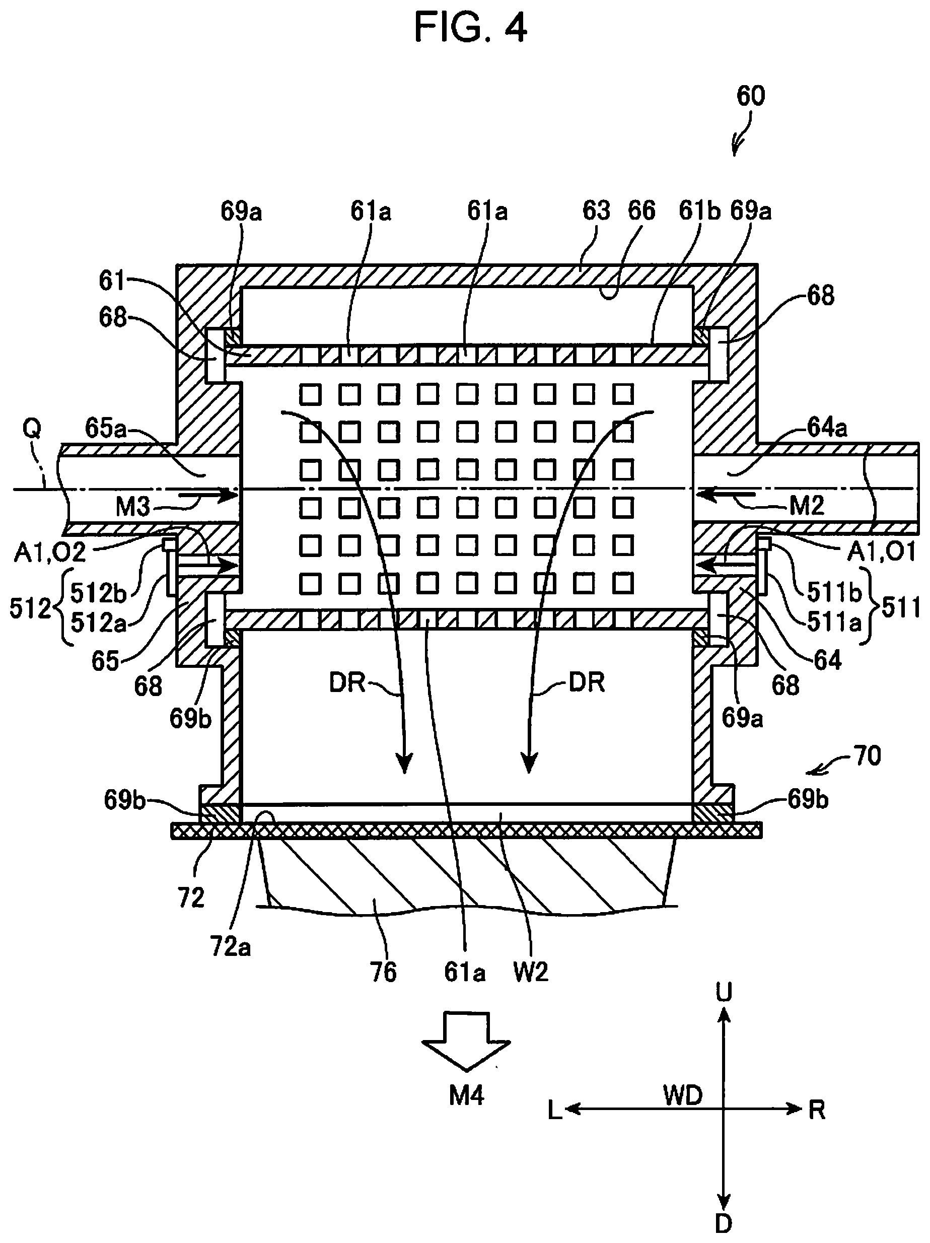
[0132] FIG. 3 is a main portion perspective view of the sheet manufacturing apparatus 100. FIG. 4 is a main portion cross-sectional view of the sheet manufacturing apparatus 100. FIG. 3 and FIG. 4 shows in detail a configuration of the depositing unit 60 and the second web forming unit 70.
[0133] As shown in FIG. 3 and FIG. 4, the drum unit 61 has a hollow cylindrical shape and can rotate around a rotation axis Q (FIG. 4). A plurality of openings 61a are formed on an outer circumferential surface 61b of the drum unit 61. When the drum unit 61 rotates, fibers that have passed through the openings 61a fall and are deposited on the mesh belt 72 to form a web W. Here, the size, shape, and number of the openings 61a formed on the drum unit 61 are not particularly limited. For convenience, in FIG. 3 and FIG. 4, the openings 61a are depicted largely with respect to the drum unit 61.
[0134] The housing portion 63 covers at least a portion where the openings 61a are formed on the drum unit 61 (the outer circumferential surface 61b where the openings 61a are formed) with a gap in between. In the examples shown in FIG. 3 and FIG. 4, the housing portion 63 has a facing wall portion 66 having an inner surface facing the outer circumferential surface 61b, a right side wall 64, and a left side wall 65, and houses the drum unit 61. The right side wall 64 and the left side wall 65 of the housing portion 63 are connected to the facing wall portion 66 and cover the drum unit 61 from a rotation axis Q direction (a direction in which the rotation axis Q extends).
[0135] Here, in the configuration of the depositing unit 60 and the second web forming unit 70, the rotation axis Q direction is defined as a left-right direction, and a right direction and a left direction are denoted by reference sign R and reference sign L, respectively. The transport direction F, the right direction R, and the left direction L are directions within a surface of the second web W2 or within a surface parallel with the surface of the second web W2. The rotation axis Q direction, that is, an R-L direction, is a direction perpendicular to the transport direction F, and corresponds to a width direction of the second web W2 and the sheet S. Therefore, the R-L direction is called a width direction WD in the description below.
[0136] A direction perpendicular to a surface including the width direction WD and the transport direction F is called an upward/downward direction, and the upward direction and a downward direction are respectively denoted by reference sign U and reference sign D.
[0137] As shown in FIG. 4, a recessed portion 68 is provided to inner surfaces of the right side wall 64 and the left side wall 65 of the housing portion 63. A pile seal 69a is provided to the recessed portion 68. The drum unit 61 is rotatably supported by the housing portion 63 through the pile seal 69a with a predetermined distance in between. The pile seal 69a is composed of, for example, a brush where fine bristles are densely implanted on a surface of a base portion.
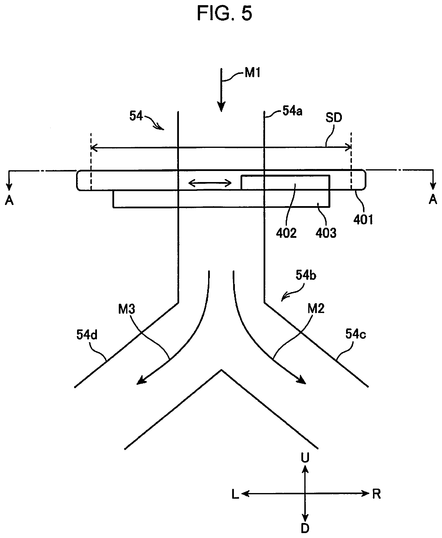
[0138] On the other hand, air containing material is supplied to the depositing unit 60 through the pipe 54 (material supply pipe). The pipe 54 has a configuration where one main pipe 54a connected to the mixing blower 56 branches into branch pipes 54c and 54d at a branch portion 54b. The branch pipe 54c is connected to an air feed pipe 57a, and the branch pipe 54d is connected to an air feed pipe 57b. The main pipe 54a corresponds to a first supply pipe, the branch pipe 54c corresponds to a second supply pipe, and the branch pipe 54d corresponds to a third supply pipe.
[0139] The mixing blower 56 sends a transport air flow M1 which is air containing material through the main pipe 54a. The transport air flow M1 is divided into a transport air flow M2 which flows through the branch pipe 54c and a transport air flow M3 which flows through the branch pipe 54d at the branch portion 54b. Here, as described above, the material is a mixture of fibers and resin, which includes the fibers (the first selected matter) separated by the selection unit 40 and the additive (resin) supplied by the additive supply unit 52.
[0140] The right side wall 64 and the left side wall 65 of the housing portion 63 are respectively connected with the air feed pipes 57a and 57b which supply air containing the material to the inside of the drum unit 61. The air feed pipe 57a penetrates the right side wall 64 and communicates with the inside of the drum unit 61. A material supply port 64a that opens to an internal space of the drum unit 61 is provided to the inside of the housing portion 63. Similarly, the air feed pipe 57b penetrates the left side wall 65 and communicates with the inside of the drum unit 61. The left side wall 65 is provided with a material supply port 65a that opens to the internal space of the drum unit 61.
[0141] The transport air flow M2 passes through the branch pipe 54c and the air feed pipe 57a and flows into the inside of the drum unit 61. The transport air flow M3 passes through the branch pipe 54d and the air feed pipe 57b and flows into the inside of the drum unit 61. The materials included in the transport air flows M2 and M3 flow into the drum unit 61 in a state in which the materials are humidified by the humidified air supplied from the humidifying unit 206.
[0142] The air feed pipes 57a and 57b penetrate the right side wall 64 and the left side wall 65, respectively. The air flows (the transport air flows M2 and M3) including the materials flow into the inside of the drum unit 61 from each of the air feed pipes 57a and 57b through the material supply ports 64a and 65a in the rotation axis Q direction. As shown in FIG. 4, the material supply port 64a is provided in a position overlapping with the rotation axis Q as seen from the rotation axis Q direction. Similarly, the material supply port 65a is also provided in a position overlapping with the rotation axis Q.
[0143] The housing portion 63 is provided with air intake ports 501 and 502 for supplying air containing no material (for example, air outside the housing portion 63) from the rotation axis Q direction of the drum unit 61 to the inside of the drum unit 61. The air intake port 501 is a through hole extending in the rotation axis Q direction and is formed by penetrating the right side wall 64. The air intake port 502 is a through hole extending in the rotation axis Q direction and is formed by penetrating the left side wall 65. Therefore, the space inside the housing portion 63 is communicated with the outside of the housing portion 63 by the air intake ports 501 and 502. One of the air intake ports 501 and 502 corresponds to a first air intake port, and the other corresponds to a second air intake port.
[0144] it is allowed that a periphery of the depositing unit 60 is surrounded by a partition wall (not shown in the drawings) and humidified air A1 is supplied to a space surrounded by the partition wall (a space in which the depositing unit 60 exists) so that the space is used as a humidified space. The humidified air A1 is air containing no material. The humidified air A1 is blown by a blower included in the humidifying unit 208 or a blower connected to the humidifying unit 208 and supplied to the humidified space.
[0145] The air intake port 501 is provided separately from the material supply ports 64a, and the air intake port 502 is provided separately from the material supply ports 65a. As shown in FIG. 4, the air intake ports 501 and 502 are provided in a position overlapping with the inside of the drum unit 61 as seen from the rotation axis Q direction.
[0146] In a configuration example shown in FIG. 3 and FIG. 4, the air intake ports 501 and 502 are provided in positions closer to the mesh belt 72 than the material supply ports 64a and 65a (positions closer from the mesh belt 72). In other words, the distances between the air intake ports 501 and 502 and the mesh belt 72 are smaller than the distances between the material supply ports 64a and 65a and the mesh belt 72.
[0147] On the other hand, the mesh belt 72 is arranged below the housing portion 63. The mesh belt 72 forms a lower surface of the housing portion 63 and protrudes to the outside of the housing portion 63 through an opening 63a formed in a lower portion of the housing portion 63. The material falling from the drum unit 61 is deposited on a deposition surface 72a which is an upper surface of the mesh belt 72.
[0148] As described above, the suction mechanism 76 is arranged below the mesh belt 72 and the suction mechanism takes in air downward through the mesh belt 72. Specifically, the suction blower 77 included in the suction mechanism 76 generates a suction air flow M4. Thereby, a down flow DF flowing in a downward direction D is generated in the inside of the housing portion 63.
[0149] As described above, in the internal space of the housing portion 63, while the transport air flows M2 and M3 flow into the drum unit 61, the suction mechanism 76 performs suction from below. Therefore, the down flow DF from the inside of the drum unit 61 to the mesh belt 72 is generated, and the material falls along with the down flow DF to the deposition surface 72a through the openings 61a.
[0150] When an air flow amount sucked by the suction mechanism 76 is greater than an air flow amount flowing into the drum unit 61 from the material supply ports 64a and 65a, outside airs O1 and O2 are flown in from the air intake ports 501 and 502, respectively, by a difference between the air flow amounts. The outside airs O1 and O2 flow into the inside of the drum unit 61 as indicated by arrows in FIG. 4 and become a part of the down flow DF. Further, as described above, when the space including the depositing unit 60 is humidified, the outside airs O1 and O2 flowing into the inside of the drum unit 61 are the humidified air A1.
[0151] When the air flow amount sucked by the suction mechanism 76 is defined as a first air flow amount and an air flow amount of the transport air flows M2 and M3 flowing into the drum unit 61 is defined as a second air flow amount, the air intake ports 501 and 502 cause the outside airs O1 and O2 to pass through corresponding to a difference between the first air flow amount and the second air flow amount. Therefore, it is possible to adjust or control the first air flow amount and the second air flow amount independently from each other by forming the air intake ports 501 and 502. When the first air flow amount is greater than the second air flow amount, there is no risk that the material leaks to the outside from the air intake ports 501 and/or 502.
[0152] A pile seal 69b is arranged between the housing portion 63 and the mesh belt 72. The pile seal 69b has, for example, a rectangular parallelepiped shape (a substantially rectangular parallelepiped shape) and is composed of, for example, a brush where fine bristles are densely implanted on a surface of a base portion. The pile seal 69b is arranged between the mesh belt 72 and the right and left side walls 64 and 65, so that it is possible to prevent the fibrillated matter from leaking from a gap between the housing portion 63 and the mesh belt 72.
[0153] Further, in the sheet manufacturing apparatus 100 of the present embodiment, an air intake regulation unit 511 is arranged to the air intake port 501 and an air intake regulation unit 512 is arranged to the air intake port 502. The air intake regulation units 511 and 512 have a common structure, so that the air intake regulation unit 512 will be described with reference to FIG. 3. The air intake regulation unit 512 has a regulation plate 512a that is arranged slidably along the left side wall 65 and a plate drive unit 512b that moves the regulation plate 512a on an exterior surface of the left side wall 65. The regulation plate 512a can slidably move between a position where the regulation plate 512a closes the air intake port 502 that opens in the left side wall 65 and a position where the regulation plate 512a does not close the air intake port 502. Therefore, it is possible to change an opening area of the air intake port 502 in the outside of the housing portion 63 by moving the regulation plate 512a. The plate drive unit 512b includes an actuator and the like, operates under control of a control apparatus 110, and moves the regulation plate 512a. The control apparatus 110 can adjust the position of the regulation plate 512a by controlling the plate drive unit 512b and can adjust the opening area of the air intake port 502. The air intake regulation units 511 and 512 correspond to a second adjustment unit.
[0154] The air intake regulation unit 511 arranged to the air intake port 501 includes a regulation plate 511a that slidably moves between a position where the regulation plate 511a closes the air intake port 501 and a position where the regulation plate 511a opens the air intake port 501 so as to change an opening area of the air intake port 501 and a plate drive unit 511b that moves the regulation plate 511a. In the same manner as the plate drive unit 512b, the plate drive unit 511b includes an actuator and the like, operates under control of the control apparatus 110, and moves the regulation plate 511a. The control apparatus 110 can adjust the opening area of the air intake port 501 that opens to the outside of the right side wall 64 by controlling the plate drive unit 511b.
[0155] An air flow amount of outside air flowing in from the air intake ports 501 and 502 is determined by the difference between the first air flow amount and the second air flow amount. Therefore, when the opening area of the air intake port 501 located in the right side wall 64 is decreased by the regulation plate 511a, ventilation resistance of the outside air O1 flowing in from the air intake port 501 increases. Accordingly, an air flow amount of the outside air O1 flowing into the drum unit 61 from the air intake port 501 decreases, and accordingly, an air flow amount of the outside air O2 flowing in from the air intake port 502 increases. On the other hand, when the opening area of the air intake port 502 located in the left side wall 65 is decreased by the regulation plate 512a, ventilation resistance of the outside air O2 flowing in from the air intake port 502 increases. Accordingly, an air flow amount of the outside air O2 flowing into the drum unit 61 from the air intake port 502 decreases, and accordingly, an air flow amount of the outside air O1 flowing in from the air intake port 501 increases. When the opening areas of the air intake ports 501 and 502 are the same, the air flow amount of the outside air O1 and the air flow amount of the outside air O2 are balanced. The control apparatus 110 can control operations of the plate drive units 511b and 512b, respectively. Therefore, it is possible to change balance of the air flow amounts of the outside airs O1 and O2 flowing into the drum unit 61 under control of the control apparatus 110. When the opening areas of the air intake ports 501 and 502 are extremely small and the suction force of the suction mechanism 76 is weak, a total air flow amount of the outside air O1 and the outside air O2 may decrease depending on the positions of the regulation plates 511a and 512a.
[0156] FIG. 5 is a main portion enlarged view of the sheet manufacturing apparatus 100 and in particular is an enlarged front view showing the pipe 54 and an air flow regulation unit 401. FIG. 6 is a cross-sectional view taken along line A-A in FIG. 5.
[0157] As described above, on the pipe 54, the air flow regulation unit 401 is arranged above the branch portion 54b. The air flow regulation unit 401 includes an air flow regulation plate 402 that can slide in a direction indicated by reference sign SD in FIGS. 5 and 6 and a plate drive unit 403 that moves the air flow regulation plate 402.
[0158] The position of the air flow regulation unit 401 is preferable to be close to the branch portion 54b, and is more preferable to be provided to a pipe before being branched at the branch portion 54b, that is, the main pipe 54a. In the main pipe 54a, it is most preferable that the air flow regulation unit 401 is close to the branch portion 54b.
[0159] The air flow regulation plate 402 slides so as to cross the main pipe 54a (along a cross section), and it is configured so that a part or all of the main pipe 54a is blocked by the flow regulation plate 402. In the inside of the main pipe 54a, a cross-section area which the transport air flow M1 can pass through varies depending on a position of the air flow regulation plate 402. The plate drive unit 403 includes an actuator and the like and slidably moves the air flow regulation plate 402 under control of the control apparatus 110.
[0160] FIG. 6 shows a relationship between a range where the air flow regulation plate 402 slidably moves and the cross-section of the main pipe 54a. The air flow regulation plate 402 does not overlap with a cross-section opening of the main pipe 54a when the air flow regulation plate 402 is located at an end of a moving range SD on a right direction R side and when the air flow regulation plate 402 is located at an end of the moving range SD on a left direction L side. In these locations, the air flow regulation plate 402 does not affect the transport air flow M1 flowing through the main pipe 54a.
[0161] When the air flow regulation plate 402 is moved in the moving range SD, the right direction R side or the left direction L side of the cross-section of the main pipe 54a is closed by the air flow regulation plate 402 depending on the location of the air flow regulation plate 402. Therefore, the air flow regulation plate 402 can affect the transport air flow M1 flowing through the main pipe 54a.
[0162] Specifically, when the air flow regulation plate 402 is overlapped with a part of the right direction R side of the cross-section of the main pipe 54a, a flow path of the transport air flow M1 becomes narrow on the right direction R side of the center (the position of the branch portion 54b shown in FIG. 6) of the main pipe 54a. That is, ventilation resistance occurs on the right direction R side in the main pipe 54a. In this state, the transport air flow M1 collides with the air flow regulation plate 402 and flows around the regulation plate 402, so that the material contained in the transport air flow M1 flows largely on the left direction L side. The material is transferred largely on the left direction L side in the main pipe 54a, so that a greater amount of material flows in the transport air flow M3 than in the transport air flow M2 in the branch portion 54b. Therefore, a greater amount of material flows into the drum unit 61 from the left direction L side than from the right direction R side. On the other hand, when the air flow regulation plate 402 is located on the left direction L side of the cross-section of the main pipe 54a, a cross-section area (opening area) on the left direction L side of the main pipe 54a decreases, so that the material contained in the transport air flow M1 flows largely on the right direction R side. Therefore, the transport air flow M2 transports a greater amount of material than the transport air flow M3, so that a greater amount of material flows into the drum unit 61 from the right side wall 64 side than from the left side wall 65 side. The air flow regulation plate 402 affects a flow velocity of the transport air flow M1 except for a case when the air flow regulation plate 402 completely closes the cross-section opening of the main pipe 54a. However, the air flow regulation plate 402 scarcely affects an air flow amount, so that the sum of the air flow amounts of the transport air flows M2 and M3 flowing into the drum unit 61 hardly changes. However, when a wind force of the mixing blower 56 that generates the transport air flows M1 is weak and a ratio of an area reduced by the air flow regulation plate 402 in the cross-section area of the main pipe 54a is large, the air flow amount may decrease.
[0163] In the depositing unit 60, it is possible to change and adjust the balance (left-right balance) of the outside airs O1 and O2 flowing into the drum unit 61 by controlling the plate drive units 511b and 512b of the air intake regulation units 511 and 512. Further, it is possible to change and adjust the balance (left-right balance) between a transport amount of material to the drum unit 61 by the transport air flow M2 and a transport amount of material to the drum unit 61 by the transport air flow M3 by controlling the plate drive unit 403 in the air flow regulation unit 401.
[0164] The sheet manufacturing apparatus 100 can make uneven a basis weight of the sheet S manufactured by the sheet manufacturing apparatus 100 in the width direction WD. Normally, the basis weight is used as a standard of quality of various papers and sheets including PPC sheets and the like used in offices. The basis weight is a kind of index or standard indicating characteristics of paper or sheet and is commonly used in paper manufacturing industry and printing industry. The basis weight is a weight per unit area of paper or sheet, and generally, g (gram)/m.sup.2 (square meter) is used as a unit. Normally, one basis weight is used for one kind of paper or sheet on the assumption that the basis weight is uniform in the entire paper or sheet.
[0165] On the other hand, the sheet manufacturing apparatus 100 can manufacture the sheet S having variation in basis weight within a surface. In the present embodiment, an example in which variation in basis weight is generated in the width direction WD of the sheet S will be described. When a direction (for example, the width direction WD) crossing the transport direction F is used as a short side direction of the sheet S that has been cut by the cutting unit 90, in the sheet S that has been cut, the basis weight is substantially constant in the length direction and there is variation (unevenness) in the basis weight in the width direction. For example, when the basis weight in a central portion in the width direction is increased and the basis weight in end portions is made smaller than that in the central portion, the sheet S has characteristics that rigidity and bending resistance are high in the central portion. For example, when the sheet S is transported by a scanner or a printing apparatus such as a printer, a transport failure such as jamming (clogging) hardly occurs because the rigidity and bending resistance are high, so that it is possible to obtain preferable characteristics such that transportability is good.
[0166] The sheet manufacturing apparatus 100 includes a basis weight sensor 309 for controlling distribution of basis weight. The basis weight sensor 309 is a sensor that detects the basis weight of the second web W2 or the sheet S. The basis weight sensor 309 may be installed anywhere after a step of forming the second web W2 in the second web forming unit 70. However, in the present embodiment, the basis weight sensor 309 is installed on a transport path of the sheet S between the sheet forming unit 80 and the cutting unit 90.
[0167] FIG. 7 and FIG. 8 are explanatory diagrams showing detection of the basis weight by the sheet manufacturing apparatus 100. FIG. 7 is a plan view showing an arrangement state of a thickness sensor. FIG. 8 is a graphic chart showing a distribution of the basis weight of the second web.
[0168] As shown in FIG. 7, in the present embodiment, the basis weight sensor 309 (a detection unit) includes a first detection unit 309a, a second detection unit 309b, and a third detection unit 309c. The first detection unit 309a, the second detection unit 309b, and the third detection unit 309c are arranged in a row in the width direction WD with respect to the transport path of the sheet S and detect the basis weight of the sheet S immediately below the detection units.
[0169] The first detection unit 309a, the second detection unit 309b, and the third detection unit 309c are, for example, reflection type optical sensors, include a light source that emit light to the sheet S and a light receiving unit that receives light reflected from the sheet S, and outputs an output value corresponding to an amount of received light.
[0170] The first detection unit 309a is arranged in a central portion in the width direction WD of the sheet S, the second detection unit 309b is arranged at an end portion on the left direction L side of the sheet S, and the third detection unit 309c is arranged at an end portion on the right direction R side in the width direction WD. Here, the central portion in the width direction WD of the sheet S is denoted by reference sign WS1, the end portion on the left direction L side is denoted by reference sign WS2, and the end portion on the right direction R side is denoted by reference sign WS3. The output value of the first detection unit 309a indicates the basis weight of the central portion WS1, the output value of the second detection unit 309b indicates the basis weight of the end portion WS2, and the output value of the third detection unit 309c indicates the basis weight of the end portion WS3. The control apparatus 110 connected to the basis weight sensor 309 can obtain the basis weights of the central portion WS1 and the end portions WS2 and WS3 of the sheet S based on the output values of the basis weight sensor 309.
[0171] The basis weight sensor 309 may have a configuration that detects the basis weight of the sheet S in the same positions as those of the first detection unit 309a, the second detection unit 309b, and the third detection unit 309c. For example, a transmission-type optical sensor may be used as the basis weight sensor 309. Further, the number of detection portions in the width direction WD need not be limited to three, and the basis weight may be detected in a greater number of portions.
[0172] When the detection is performed in a state before the sheet forming unit 80 performs pressurizing and heating, that is, when the detection is performed on the second web W2, a sensor that detects a thickness can be used instead of the sensor that detects the basis weight. For example, a sensor that comes into contact with the second web W2 and detects the thickness of the second web W2 is arranged, and the detection may be performed by this sensor in a plurality of positions in the width direction WD. The basis weight of the second web W2 is determined by a thickness of the material deposited on the mesh belt 72, so that when the thickness of the second web W2 is measured, the measured thickness can be converted into the basis weight. When the second web W2 is pressurized and heated into a shape of the sheet S, the basis weight and the thickness may not have a sufficient correlation. Therefore, when the basis weight is measured in the downstream of the sheet forming unit 80, more specifically, in the downstream of the pressurizing unit 82, it is preferable to have a configuration where the basis weight is measured by using an optical sensor or the like such as the basis weight sensor 309.
[0173] FIG. 8 shows an example of a distribution of the basis weight of the sheet S detected by the control apparatus 110 based on the output values of the basis weight sensor 309. In the graphic chart of FIG. 8, the horizontal axis indicates a position in the width direction WD and the vertical axis indicates the basis weight. When the thickness of the second web W2 is detected by using a sensor other than the basis weight sensor 309, the vertical axis may be replaced with the thickness.
[0174] For example, as shown in FIG. 8, under control of the control apparatus 110, the sheet manufacturing apparatus 100 can manufacture the sheet S having a distribution where the basis weight of the central portion in the width direction WD is large and the basis weights of the end portions on the right direction R side and the left direction L side are smaller than that of the central portion. Here, a direction in which variation is generated in the basis weight distribution of the sheet S may be a predetermined direction crossing the transport direction F of the second web W2 and the sheet S and is not limited to the width direction WD perpendicular to the transport direction F.
[0175] Advantages of manufacturing this type of sheet S will be described.
[0176] The sheet S described above can be used in a printer, a scanner, and the like which transport the sheet S. In particular, it is useful when a transport direction, in which an apparatus having a mechanism that pinches the sheet S with a transport roller pair and transports the sheet S transports the sheet S, is a direction crossing a predetermined direction (the width direction WD in the present embodiment) of the sheet S. In this case, the sheet S is rigid in the transport direction of the apparatus, so that the sheet S is excellent in transportability. While the sheet S exhibits strength corresponding to the basis weight of the central portion, the basis weight of the entire sheet S is suppressed because the basis weights of end portions are smaller than that of the central portion. Therefore, there are advantages that the sheet S has rigidity and high transportability and sheet S is light because the basis weight is small. Further, there is an advantage that the amount of material required to manufacture the sheet S is smaller than that when the basis weight of the entire sheet S is increased.
[0177] The sheet S may have a configuration where the thickness of end portions in a predetermined direction becomes the same as that of the central portion after the sheet S is pressurized and heated in the sheet forming unit 80 although there is variation in a distribution of the basis weight in the predetermined direction. In this case, there is an advantage that the sheet S is excellent in transportability and rigidity in the transport direction due to the distribution of basis weight and the sheet S has no unevenness in the thickness. "Having the same thickness" is not limited to having an identical thickness, but "the same thickness" may be substantially the same thickness including an error.
[0178] FIG. 9 is a block diagram showing a configuration of a control system of the sheet manufacturing apparatus 100.
[0179] The sheet manufacturing apparatus 100 includes the control apparatus 110 having a main processor 111 that controls each component of the sheet manufacturing apparatus 100.
[0180] The control apparatus 110 includes the main processor 111, a ROM (Read Only Memory) 112, and a RAM (Random Access Memory) 113. The main processor 111 is an arithmetic processing apparatus such as a CPU (Central Processing Unit) and controls each component of the sheet manufacturing apparatus 100 by executing a basic control program stored in the ROM 112. The main processor 111 may be configured as a system chip including peripheral circuits such as the ROM 112 and the RAM 113 and other IP cores.
[0181] The ROM 112 stores the program to be executed by the main processor 111 in a non-volatile manner. The RAM 113 forms a work area to be used by the main processor 111 and temporarily stores a program to be executed by the main processor 111 and data to be processed.
[0182] A non-volatile storage unit 120 stores a program to be executed by the main processor 111 and data to be processed by the main processor 111.
[0183] The display panel 116 is a panel for display such as a liquid crystal display and is installed on, for example, a front surface of the sheet manufacturing apparatus 100. The display panel 116 displays an operation state, various setting values, a warning display, and the like of the sheet manufacturing apparatus 100 according to control of the main processor 111.
[0184] The touch sensor 117 detects a touch (contact) operation and a pressing operation. The touch sensor 117 is composed of, for example, a pressure sensing type sensor or an electrostatic capacity type sensor and is arranged overlapped on a display surface of the display panel 116. When detecting an operation, the touch sensor 117 outputs operation data including operation positions and the number of the operation positions to the main processor 111. The main processor 111 detects the operation on the display panel 116 by the output from the touch sensor 117 and acquires the operation positions. The main processor 111 realizes a GUI (Graphical User Interface) operation based on the operation positions detected by the touch sensor 117 and display data 122 that is being displayed on the display panel 116.
[0185] The control apparatus 110 is connected to sensors installed in each component of the sheet manufacturing apparatus 100 through a sensor I/F (Interface) 114. The sensor I/F 114 is an interface that acquires detection values outputted from the sensors and inputs the detection values to the main processor 111. The sensor I/F 114 may include an A/D (Analogue/Digital) converter that converts an analog signal outputted from the sensors into digital data. The sensor I/F 114 may supply drive current to each sensor. The sensor I/F 114 may include a circuit that acquires an output value of each sensor according to a sampling frequency specified by the main processor 111 and outputs the output value to the main processor 111.
[0186] The sensor I/F 114 is connected with a waste paper remaining amount sensor 301, a paper discharge sensor 303, and the basis weight sensor 309.
[0187] The waste paper remaining amount sensor 301 detects a remaining amount of waste paper stored in the supply unit 10. For example, when the remaining amount of waste paper detected by the waste paper remaining amount sensor 301 falls below a setting value, the control unit 150 notifies of shortage of the waste paper.
[0188] The paper discharge sensor 303 detects the amount of sheets S accumulated in a tray or a stacker included in the discharge unit 96. When the amount of sheets S detected by the paper discharge sensor 303 becomes a setting value or more, the control unit 150 performs notification.
[0189] As described above, the basis weight sensor 309 is arranged along the transport path of the sheet S and detects the basis weight of the sheet S by performing optical reading on the sheet S. The basis weight sensor 309 outputs a detection value of the optical detection to the control apparatus 110. The basis weight sensor 309 detects the basis weight in a plurality of positions in a predetermined direction (the width direction WD in the present embodiment) crossing the transport direction of the sheet S. The control apparatus 110 can detect a distribution of the basis weight in the predetermined direction of the sheet S based on a detection result (output values) of the basis weight sensor 309. As described above, the basis weight sensor 309 may be installed in the transport path of the second web W2 instead of the transport path of the sheet S and perform the detection on the second web W2.
[0190] The configuration shown in FIG. 9 is an example, and for example, the sheet manufacturing apparatus 100 may have other sensors and the control apparatus 110 may acquire detection values of the other sensors. For example, the sheet manufacturing apparatus 100 may include a sensor that detects a remaining amount of the additive in the additive supply unit 52, a sensor that detects an amount of water in a tank (not shown in the drawings) that stores water for humidifying, and the like. Further, the sheet manufacturing apparatus 100 may include sensors that detect a temperature, an air flow amount, and an air flow velocity of the air flowing inside the sheet manufacturing apparatus 100.
[0191] The control apparatus 110 is connected to each drive unit included in the sheet manufacturing apparatus 100 through a drive unit I/F (Interface) 115. The drive units included in the sheet manufacturing apparatus 100 are a motor, a pump, a heater, and the like.
[0192] The drive unit I/F 115 is connected with a rough-crushing unit 311, a fibrillating unit 312, a paper feed motor 313, an additive supply unit 314, a blower 315, a humidifying unit 316, a drum unit drive unit 317, a belt drive unit 318 and a dividing unit 319 as objects to be controlled by the control apparatus 110.
[0193] The rough-crushing unit 311 includes a drive unit such as a motor that rotates a cutting blade (not shown in the drawings) that cuts waste paper which is a raw material in the rough-crushing unit 12. The fibrillating unit 312 includes a drive unit such as a motor that rotates a rotor (not shown in the drawings) included in the fibrillating unit 20. The paper feed motor 313 is a motor that supplies waste paper from the supply unit 10. The additive supply unit 314 includes drive units such as a motor that drives a screw feeder that feeds out the additive in the discharge unit 52a, a motor that opens and closes the discharge unit 52a, and an actuator. The blower 315 includes the fibrillating unit blower 26, the collection blower 28, the mixing blower 56, the suction blower 77, and the like. Each of these blowers may be individually connected to the drive unit I/F 115.
[0194] The humidifying unit 316 includes the humidifying units 202, 204, 206, and 208, which are composed of a vaporizing type or a hot air vaporizing type humidifier, and the humidifying units 210 and 212, which are composed of an ultrasonic type humidifier that generates mist.
[0195] The drum unit drive unit 317 includes drive units such as a motor that rotates the drum unit 41 and a motor that rotates the drum unit 61.
[0196] A belt drive unit 318 includes drive units such as a motor that drives the mesh belt 46, a motor that drives the mesh belt 72, and a motor that drives the mesh belt 79a. The belt drive unit 318 may include detection units such as a rotary encoder and a rotation angle sensor that detect a rotation velocity, a rotation amount, a rotation angle, and the like of the above motors.
[0197] The dividing unit 319 includes a drive unit such as a motor that rotates the rotating body 49.
[0198] A basis weight adjustment unit 341 is a drive unit that operates under control of the control apparatus 110. The basis weight adjustment unit 341 changes or adjusts at least one of an air flow direction, an air flow amount, an air flow velocity, and their left-right balance for the transport air flows M1, M2, and M3 of the material flowing into the depositing unit 60. In the present embodiment, the plate drive unit 403 that drives the air flow regulation unit 401 corresponds to the basis weight adjustment unit 341.
[0199] An air intake adjustment unit 342 is a drive unit that operates under control of the control apparatus 110. The air intake adjustment unit 342 changes or adjusts at least one of an air flow direction, an air flow amount, an air flow velocity, and their left-right balance for air containing no material, which is sucked by the depositing unit 60. In the present embodiment, the air intake regulation units 511 and 512 correspond to the air intake adjustment unit 342, and more specifically, the plate drive units 511b and 512b correspond to the air intake adjustment unit 342. The plate drive units 511b and 512b may be operated independently from each other by control of the control apparatus 110 or may operate interlocking with each other.
[0200] FIG. 10 is a functional block diagram of the sheet manufacturing apparatus 100 and shows a functional configuration of a storage unit 140 and the control unit 150. The storage unit 140 is a logical storage unit composed of the non-volatile storage unit 120 (FIG. 9).
[0201] The control unit 150 and various functional units included in the control unit 150 are formed by cooperation of software and hardware when the main processor 111 executes a program. The hardware constituting these functional units is, for example, the main processor 111 and the non-volatile storage unit 120.
[0202] The storage unit 140 stores, for example, setting data 121, display data 122, and basis weight setting data 123. The setting data 121 includes data that sets operation of the sheet manufacturing apparatus 100. For example, the setting data 121 includes data such as a threshold value used in processing where the main processor 111 detects abnormality based on characteristics of various sensors included in the sheet manufacturing apparatus 100 and detection values of the various sensors. The display data 122 is data of a screen which the main processor 111 causes the display panel 116 to display. The display data 122 may be fixed image data or may be data that sets a screen display that displays data generated or acquired by the main processor 111.
[0203] The basis weight setting data 123 is data that associates a distribution of the basis weight of the sheet S manufactured by the sheet manufacturing apparatus 100 with an operation condition and the like of the sheet manufacturing apparatus 100.
[0204] The sheet manufacturing apparatus 100 can manufacture the sheets S of various conditions by controlling the basis weight adjustment unit 341 and/or the air intake adjustment unit 342 by the control apparatus 110. Specifically, it is possible to change the distribution of the basis weight in a predetermined direction of the sheet S by operations of the basis weight adjustment unit 341 and/or the air intake adjustment unit 342. Therefore, it is possible to fine-tune driving amounts and the like of the basis weight adjustment unit 341 and/or the air intake adjustment unit 342 in order to obtain a desired state of the basis weight distribution in a predetermined direction of the sheet S.
[0205] Further, in the sheet manufacturing apparatus 100 of the present embodiment, regarding the basis weight distribution in a predetermined direction of the sheet S, one or more basis weight distributions are preset in a selectable manner in advance. Specifically, one or more basis weight distributions and a parameter that defines operations of the basis weight adjustment unit 341 and/or the air intake adjustment unit 342 for realizing each basis weight distribution are associated with each other and stored in the storage unit 140. This data corresponds to the basis weight setting data 123. According to this configuration, when one basis weight distribution is selected from selectable basis weight distributions, a drive parameter of the basis weight adjustment unit 341 and/or the air intake adjustment unit 342 corresponding to the selected basis weight distribution is acquired from the basis weight setting data 123. Then, the sheet manufacturing apparatus 100 operates according to the drive parameter. Thereby, it is possible to quickly manufacture the sheet S having the selected basis weight distribution without performing an operation to adjust operation amounts and the like of the basis weight adjustment unit 341 and/or the air intake adjustment unit 342, and it is also possible to change the basis weight distribution of the sheet S.
[0206] The control unit 150 has functions of an operating system (OS) 151, a display control unit 152, an operation detection unit 153, a detection control unit 154, a drive control unit 155, and a basis weight adjustment control unit 157.
[0207] The function of the operating system 151 is a function of a control program stored in the storage unit 140, and the other units of the control unit 150 are functions of an application program executed on the operating system 151.
[0208] The display control unit 152 causes the display panel 116 to display an image based on the display data 122.
[0209] The operation detection unit 153 detects an operation performed on the touch sensor 117. The operation detection unit 153 identifies content of a GUI operation corresponding to an operation position of the operation detected on the touch sensor 117.
[0210] The detection control unit 154 acquires detection values of various sensors connected to the sensor I/F 114. The detection control unit 154 compares a detection value of a sensor connected to the sensor I/F 114 with a preset threshold value (setting value) and performs determination. When a determination result corresponds to a condition to perform notification, the detection control unit 154 outputs notification content to the display control unit 152 and causes the display control unit 152 to perform notification using image and text.
[0211] The drive control unit 155 controls start (boot) and stop of each drive unit connected through the drive unit I/F 115. Further, the drive control unit 155 may perform rotational speed control on the fibrillating unit blower 26, the mixing blower 56, and the like.
[0212] When a setting related to the basis weight distribution is performed by an operation detected by the operation detection unit 153, the basis weight adjustment control unit 157 refer to the basis weight setting data 123. The basis weight adjustment control unit 157 acquires a drive parameter of the basis weight adjustment unit 341 and/or the air intake adjustment unit 342 corresponding to the setting from the basis weight setting data 123. The basis weight adjustment control unit 157 determines driving amounts of the basis weight adjustment unit 341 and the air intake adjustment unit 342 according to the acquired drive parameter and operates the basis weight adjustment unit 341 and the air intake adjustment unit 342.
[0213] The basis weight adjustment control unit 157 causes the basis weight sensor 309 to perform detection, acquires output values of the basis weight sensor 309, and obtains the basis weight distribution of the sheet S based on the acquired output values. The basis weight adjustment control unit 157 compares the basis weight distribution of the sheet S set by an operation detected by the operation detection unit 153 with the basis weight distribution obtained from the output values of the basis weight sensor 309 and determines whether or not the basis weight distribution is in a target state. When the basis weight distribution deviates from a range that can be regarded the target state, the basis weight adjustment control unit 157 performs control so that the basis weight distribution of the sheet S is in the target state by adjusting the drive parameter of the basis weight adjustment unit 341 and the air intake adjustment unit 342.
[0214] FIG. 11 is a flowchart showing an operation of the sheet manufacturing apparatus 100.
[0215] When the power of the sheet manufacturing apparatus 100 is turned on (step ST1), the control unit 150 starts setting of operation of the sheet manufacturing apparatus 100 (step ST2). For example, the setting of operation of the sheet manufacturing apparatus 100 is performed when the display unit 160 displays a screen for the setting and a user performs an input operation on the screen for the setting. After the size, the number, and the like of the sheets S to be manufactured by the sheet manufacturing apparatus 100 are set, the control unit 150 causes the display unit 160 to display a target distribution selection screen 160a (step ST3).
[0216] FIG. 12 is a schematic diagram showing a display example of the sheet manufacturing apparatus 100 and shows an example of the target distribution selection screen 160a. In the target distribution selection screen 160a illustrated in FIG. 12, a name of the screen is displayed and a basis weight distribution selection image 162 and a selection state display portion 163 are arranged.
[0217] The basis weight distribution selection image 162 is an operation image for a user to specify the basis weight distribution of the sheet S. The basis weight distribution selection image 162 includes images 162a, 162b, and 162c corresponding to types of basis weight distribution of the sheet S that can be set in the sheet manufacturing apparatus 100. An image expressing the basis weight distribution of the sheet S is included in each of the images 162a, 162b, and 162c. When a touch operation is performed on one of the images 162a, 162b, and 162c, the basis weight distribution corresponding to the image on which the touch operation is performed is selected. The images 162a, 162b, and 162c may include characters representing the basis weight distribution of the sheet S in a language expression or may include a number previously given to the basis weight distribution of the sheet S.
[0218] The selection state display portion 163 is an image indicating that a touch operation on the image 162a, 162b, or 162c of the basis weight distribution selection image 162 is detected. In other words, the selection state display portion 163 is an image indicating the basis weight distribution selected by the touch operation among the images 162a, 162b, and 162c.
[0219] In this way, the user can easily select the basis weight distribution of the sheet S to be manufactured by the sheet manufacturing apparatus 100 from a plurality of states of the basis weight distribution by using the target distribution selection screen 160a.
[0220] The control unit 150 determines whether or not the basis weight distribution is selected by the touch operation performed on the display unit 160 and the setting is completed (step ST4). When the setting is not completed (step ST4; No), the control unit 150 waits until the basis weight distribution is selected. When the setting is completed (step ST4; Yes), the control unit 150 acquires and sets the drive parameter of the basis weight adjustment unit 341 and/or the air intake adjustment unit 342 based on data of the basis weight setting data 123 (step ST5).
[0221] Subsequently, the control unit 150 adjusts a driving state of the basis weight adjustment unit 341 and the air intake adjustment unit 342 according to the set drive parameter (step ST6).
[0222] The control unit 150 starts a start-up sequence that initializes each component of the sheet manufacturing apparatus 100 (step ST7) and proceeds to a state where the sheet S can be manufactured. In the start-up sequence, various motors, blowers, and the like controlled by the drive control unit 155 are appropriately started in a proper order. In the start-up sequence, each component including the basis weight adjustment unit 341 and the air intake adjustment unit 342 operates according to setting values.
[0223] The control unit 150 starts detection using the basis weight sensor 309 while the start-up sequence is being performed or after the start-up sequence is performed, and performs the detection using the basis weight sensor 309 at a sampling period (step ST9). The control unit 150 detects the basis weight distribution in a predetermined direction of the sheet S based on the output values of the basis weight sensor 309 (step ST10) and determines whether or not a calculated basis weight distribution corresponds to the state selected in step ST4 (step ST11). In step ST11, even when the basis weight distribution obtained from the output values of the basis weight sensor 309 is not completely coincident with the basis weight distribution set in the step ST4, if the basis weight distribution is within an allowable range, the control unit 150 makes a positive determination. For example, a variation range of allowable basis weight distribution may be previously set in the control unit 150. Alternatively, the basis weight distribution of the sheet S and a range that can be regarded as the basis weight distribution may be set in the basis weight setting data 123.
[0224] When the basis weight distribution is in a target state or in a range that can be regarded as the target state (step ST11; Yes), the control unit 150 notifies that the basis weight distribution of the sheet S is in a state selected by the user by display of the display unit 160 or the like (step ST12).
[0225] The control unit 150 determines whether or not to end operation of the sheet manufacturing apparatus 100 (step ST13). When a trigger for ending the operation is not established (step ST13; No), the control unit 150 continues the operation. When a trigger for stopping the operation such as an instruction to stop operation occurs (step ST13; Yes), the control unit 150 executes a stop sequence (step ST14).
[0226] On the other hand, when the basis weight distribution is not in the range that can be regarded as the target state (step ST11; No), the control unit 150 changes a drive parameter of the sheet manufacturing apparatus 100 (step ST15) and returns to step ST9. More specifically, the control unit 150 changes the drive parameter of the basis weight adjustment unit 341 and the air intake adjustment unit 342 so that the basis weight distribution of the sheet S obtained based on the output values of the basis weight sensor 309 approaches the target state. The control unit 150 performs adjustment of operation states of the basis weight adjustment unit 341 and the air intake adjustment unit 342 according to the drive parameter changed in step ST15 (step ST16) and returns to step ST9.
[0227] As described above, the sheet manufacturing apparatus 100 of the first embodiment includes the drum unit 61 having a plurality of openings 61a. Further, the sheet manufacturing apparatus 100 includes the second web forming unit 70 that has the deposition surface 72a, on which material containing fibers that has passed through the openings 61a is deposited, and forms the second web W2 on the deposition surface 72a, and the sheet forming unit 80 that processes the second web W2 and forms the sheet S. Further, the sheet manufacturing apparatus 100 includes the control unit 150 that controls the basis weight of the second web W2 deposited on the deposition surface 72a in a direction crossing a transport direction of the second web W2.
[0228] According to the sheet manufacturing apparatus 100, a control method of the sheet manufacturing apparatus 100, and a sheet manufacturing method, to which the present invention is applied, the basis weight distribution of the sheet S to be manufactured can be controlled by controlling the basis weight of the second web W2. Thereby, it is possible to realize a desired basis weight distribution in the sheet S. For example, by making the basis weight in a central portion greater than that in end portions in a predetermined direction (for example, in the width direction WD) within a surface of the sheet S, it is possible to manufacture a sheet S whose rigidity in the predetermined direction is high and whose transportability is high when being transported by a printer or the like.
[0229] The drum unit 61 is rotatably configured and the drum unit 61 is arranged with the pipe 54 for supplying the transport air flow M1 containing material to inside of the drum unit 61. The pipe 54 has the main pipe 54a, the branch pipe 54c, and the branch pipe 54d. The branch pipe 54c is branched from the main pipe 54a at the branch portion 54b and is connected to one end portion in a rotation axis direction of the drum unit 61. The branch pipe 54d is branched from the main pipe 54a at the branch portion 54b and is connected to the other end portion in the rotation axis direction of the drum unit 61. Further, the drum unit 61 includes the air flow regulation unit 401, which is provided near the branch portion 54b, for changing a ratio between a transport amount of material transported by the transport air flow M2 flowing through the branch pipe 54c, and a transport amount of material transported by the transport air flow M3 flowing through the branch pipe 54d under control of the control unit 150. Thereby, it is possible to change a ratio of materials supplied to the drum unit 61 by changing the ratio between the transport amount of material transported by the transport air flow M2 that supplies the material to the drum unit 61 from one side, and the transport amount of material transported by the transport air flow M3 that supplies the material to the drum unit 61 from the other side. Therefore, the basis weight distribution of the sheet S to be manufactured can be controlled by changing distribution of the material deposited through the openings 61a of the drum unit 61.
[0230] Further, the drum unit 61 includes the housing portion 63 that covers at least a portion, where the openings 61a are formed, of the drum unit 61, and the material supply ports 64a and 65a for supplying the transport air flow M1 containing material to the inside of the drum unit 61. The drum unit 61 includes the air intake port 501 and the air intake port 502 which are provided away from each other in the rotation axis direction of the drum unit 61 and which are air intake ports for supplying the outside airs O1 and O2 that are air containing no material from the outside of the housing portion 63 to the inside of the drum unit 61. Further, the drum unit 61 includes the air intake regulation units 511 and 512 that change a ratio of flow rates of air supplied from the air intake ports 501 and 502 under control of the control unit 150. According to this configuration, a distribution of air flow flowing out from the drum unit 61 can be changed by changing a ratio between the outside air O1 and the outside air O2 flowing into the drum unit 61. Therefore, the basis weight distribution of the sheet S to be manufactured can be controlled by changing the distribution in the width direction WD of the material deposited through the openings 61a of the drum unit 61.
[0231] The control unit 150 may control the flow rate of the transport air flow M1. For example, the control unit 150 may control the air flow amounts of the transport air flows M1, M2, and M3 by controlling an air blowing amount of the mixing blower 56. In this case, it is possible to more effectively control the distribution of the material deposited on the deposition surface 72a.
[0232] Further, the control unit 150 may control the flow rate of the suction air flow M4. For example, the control unit 150 may control the air flow amount of the suction air flow M4 by controlling an air blowing amount of the suction blower 77. In this case, it is possible to more effectively control the distribution of the material deposited on the deposition surface 72a.
[0233] The sheet manufacturing apparatus 100 includes the second web forming unit 70 that forms the second web W2 by depositing a material containing fibers on the deposition surface 72a and the sheet forming unit 80 that forms the sheet S by processing the second web W2. Further, the sheet manufacturing apparatus 100 has the operation detection unit 153 used as a receiving unit that receives a setting of the basis weight distribution of the sheet S and the control unit 150 that controls the basis weight of the second web W2 to be deposited on the deposition surface 72a of the second web forming unit 70 based on the basis weight distribution received by the operation detection unit 153.
[0234] According to this configuration, when manufacturing the sheet S by depositing a material containing fibers, it is possible to manufacture the sheet S of a set basis weight by controlling the basis weight of the second web W2 according to a setting of the basis weight of the sheet S. Thereby, it is possible to realize (on demand) a desired basis weight distribution in the sheet S. For example, by making the basis weight in a central portion greater than that in end portions in a predetermined direction within a surface of the sheet S, it is possible to manufacture the sheet S whose rigidity in the predetermined direction is high and whose transportability is high when being transported by a printer or the like.
[0235] The sheet manufacturing apparatus 100 has the drum unit 61, where a plurality of openings 61a are formed, and is configured so that a material that has passed through the openings 61a of the drum unit 61 is deposited on the deposition surface 72a. The operation detection unit 153 receives a basis weight distribution in a predetermined direction (the width direction WD) crossing the transport direction F of the second web W2 as the basis weight distribution of the sheet S by using, for example, the target distribution selection screen 160a. Thereby, when the basis weight distribution in a predetermined direction crossing the transport direction of the second web W2 is set, it is possible to manufacture the sheet S having the set basis weight distribution by controlling the basis weight distribution of the second web W2.
[0236] Further, the sheet manufacturing apparatus 100 includes the basis weight sensor 309 that detects the thickness or the basis weight of the second web W2 or the sheet S. The basis weight sensor 309 of the present embodiment detects the basis weight of the sheet S. The control unit 150 controls the basis weight distribution of the second web W2 in a predetermined direction crossing the transport direction F based on a detection result of the basis weight sensor 309. In this case, the basis weight distribution of the sheet S can be more properly controlled.
[0237] The sheet S manufactured by the sheet manufacturing apparatus 100 described above and the sheet manufacturing method of the sheet manufacturing apparatus 100 is provided with variation in the basis weight distribution in a predetermined direction crossing the transport direction of the sheet S when the sheet S is transported by being pinched by a transport roller pair. In the sheet S, the basis weight in the central portion is greater than that in the end portions in a predetermined direction. Thereby, it is possible to realize the sheet S which is rigid in the transport direction and excellent in transportability when being transported by the roller pair as compared with a sheet where the basis weight is substantially uniform in the entire sheet. The sheet S may be manufactured so that the thickness of the end portions in a predetermined direction is the same as that of the central portion. In this case, it is possible to realize the sheet S that is excellent in rigidity in the transport direction and transportability due to the basis weight distribution and has no unevenness in thickness.
Second Embodiment
[0238] FIG. 13 is a main portion enlarged view of a sheet manufacturing apparatus 101 according to a second embodiment to which the present invention is applied, and in particular, is an enlarged front view showing the pipe 54 and an air flow regulation unit 411.
[0239] The sheet manufacturing apparatus 101 is configured in the same manner as the sheet manufacturing apparatus 100 (FIG. 1) except for the air flow regulation unit 411 described below, so that the same components are denoted by the same reference signs, and their description will be omitted.
[0240] The air flow regulation unit 411 shown in FIG. 13 is arranged above (on the upstream side of) the branch portion 54b of the pipe 54. The air flow regulation unit 411 has plate-shaped air flow regulation rotary plates 412 arranged from the side wall side of the main pipe 54a toward the axis center and rotary units 413 that rotates the flow regulation rotary plates 412 in directions indicated by arrows RD in FIG. 13. In the example of FIG. 13, a pair of air flow regulation rotary plates 412 are respectively arranged on the right direction R side and the left direction L side of the main pipe 54a. Each flow regulation rotary plate 412 is rotated independently by the rotary unit 413 under control of the control apparatus 110.
[0241] The positions of the pair of air flow regulation rotary plates 412 correspond to a position facing the branch pipe 54c and a position facing the branch pipe 54d with reference to a flow dividing position 54e at which the branch portion 54b divides the transport air flow M1.
[0242] The air flow regulation unit 411 is installed instead of the air flow regulation unit 401 (FIG. 5) described in the first embodiment. In other words, the sheet manufacturing apparatus 101 has a configuration in which the air flow regulation unit 401 of the sheet manufacturing apparatus 100 is replaced with the air flow regulation unit 411.
[0243] The air flow regulation unit 411 includes the pair of air flow regulation rotary plates 412 and the rotary units 413 that moves the pair of air flow regulation rotary plates 412.
[0244] The position of the air flow regulation unit 411 is preferable to be close to the branch portion 54b, and is more preferable to be provided to a pipe before being branched at the branch portion 54b, that is, the main pipe 54a. In the main pipe 54a, it is most preferable that the air flow regulation unit 411 is close to the branch portion 54b.
[0245] The air flow regulation rotary plate 412 is rotated by the rotary unit 413 and is displaced between a position where the air flow regulation rotary plate 412 traverses along the cross-section opening of the main pipe 54a and a position where the air flow regulation rotary plate 412 is along the axis direction of the main pipe 54a. The area in which the air flow regulation rotary plate 412 extends in a cross-section direction of the main pipe 54a is determined by a rotation amount of the rotary unit 413. Therefore, in the inside of the main pipe 54a, a cross-section area which the transport air flow M1 can pass through is changed by an operation of the rotary unit 413. The rotary unit 413 corresponds to the basis weight adjustment unit 341. The control apparatus 110 can control on/off of the operation of the rotary unit 413 and the rotation amount of the rotary unit 413. The control apparatus 110 may control each of the pair of rotary units 413 independently or may control the pair of rotary units 413 in an interlocking manner. As shown in FIG. 13, it is preferable that the air flow regulation rotary plates 412 are rotated on the downstream side of the rotary units 413. Thereby, it is possible to suppress stagnation of material in the air flow regulation unit 411.
[0246] When the air flow regulation rotary plate 412 is rotated, a flow of the transport air flow M1 is prevented by the air flow regulation rotary plate 412 on the right direction R side or the left direction L side of the cross-section of the main pipe 54a. That is, the air flow regulation rotary plate 412 can affect the transport air flow M1 flowing through the main pipe 54a.
[0247] For example, when the air flow regulation rotary plate 412 located on the right direction R side extends toward the central position of the main pipe 54a, the flow path of the transport air flow M1 becomes narrow on the right direction R side of the flow dividing position 54e which is located in the central position of the main pipe 54a. Therefore, ventilation resistance occurs on the right direction R side in the main pipe 54a. In this state, the transport air flow M1 collides with the air flow regulation rotary plate 412 and flows around the air flow regulation rotary plate 412, so that the material contained in the transport air flow M1 flows largely on the left direction L side. The material is transferred largely on the left direction L side in the main pipe 54a, so that a greater amount of material flows in the transport air flow M3 than in the transport air flow M2 in the branch portion 54b. Therefore, a greater amount of material flows into the drum unit 61 from the left direction L side than from the right direction R side.
[0248] On the other hand, when the air flow regulation rotary plate 412 located on the left direction L side extends toward the central position of the main pipe 54a, the flow path of the transport air flow M1 becomes narrow on the left direction L side of the flow dividing position 54e which is located in the central position of the main pipe 54a. Therefore, ventilation resistance occurs on the left direction L side in the main pipe 54a. In this state, the transport air flow M1 collides with the air flow regulation rotary plate 412 and flows around the air flow regulation rotary plate 412, so that the material contained in the transport air flow M1 flows largely on the right direction R side. The material is transferred largely on the right direction R side in the main pipe 54a, so that a greater amount of material flows in the transport air flow M2 than in the transport air flow M3 in the branch portion 54b. Therefore, a greater amount of material flows into the drum unit 61 from the right direction R side than from the left direction L side.
[0249] The air flow regulation rotary plate 412 affects a flow velocity of the transport air flow M1. However, the air flow regulation rotary plate 412 scarcely affects an air flow amount, so that the sum of the air flow amounts of the transport air flows M2 and M3 flowing into the drum unit 61 hardly changes. However, when a wind force of the mixing blower 56 that generates the transport air flows M1 is weak and a ratio of an area reduced by the air flow regulation rotary plates 412 in the cross-section area of the main pipe 54a is large, the air flow amount may decrease.
[0250] According to the sheet manufacturing apparatus 101 of the second embodiment, the air flow regulation unit 411 is controlled by the basis weight adjustment control unit 157, and thereby a left-right balance of the material flowing into the drum unit 61 from the pipe 54 can be changed. The effect of the above is the same as the effect obtained when the air flow regulation unit 401 is controlled by the basis weight adjustment control unit 157 in the first embodiment.
[0251] Therefore, the sheet manufacturing apparatus 101 of the second embodiment achieves the same effects as those of the sheet manufacturing apparatus 100. Further, the air flow regulation rotary plate 412 included in the air flow regulation unit 411 can be realized with a size smaller than that of the air flow regulation plate 402 included in the air flow regulation unit 401 (FIG. 5). Therefore, when a margin space outside the main pipe 54a is small, the flow regulation unit 411 is more advantageous.
[0252] In the second embodiment described above, the pipe 54 is not limited to a circular cross-section tube, but may be a rectangular cross-section tube. Specifically, at least in a position where the air flow regulation unit 411 is provided, the main pipe 54a is composed of a rectangular (square) cross-section tube. In this case, a rectangular plate is used as the air flow regulation rotary plate 412, so that a pair of air intake regulation units 412 can more effectively affect a flow of the transport air flow M1. Therefore, it is possible to efficiently adjust the distribution of material in the drum unit 61.
Third Embodiment
[0253] FIG. 14 is a main portion perspective view of a sheet manufacturing apparatus 102 according to a third embodiment, and in particular, shows a configuration of the depositing unit 60 and the second web forming unit 70.
[0254] The sheet manufacturing apparatus 102 is configured in the same manner as the sheet manufacturing apparatus 100 (FIG. 1) except for a depositing unit 60a described below, so that the same components are denoted by the same reference signs, and their description will be omitted. The sheet manufacturing apparatus 102 has a configuration in which the depositing unit 60 (FIG. 3) of the sheet manufacturing apparatus 100 is replaced with the depositing unit 60a, and air supply pipes 522a and 522b and air supply apparatuses 523a and 523b are provided.
[0255] The depositing unit 60a includes a right side wall 64b instead of the right side wall 64 (FIG. 3) and a left side wall 65b instead of the left side wall 65 (FIG. 3). The right side wall 64b is connected with the air feed pipe 57a in the same manner as the right side wall 64, and the transport air flow M2 containing material is supplied from the air feed pipe 57a to the inside of the drum unit 61. The right side wall 64b has the material supply port 64a which opens in a position corresponding to the inside of the drum unit 61 and from which the transport air flow M2 flows in.
[0256] The left side wall 65b is connected with the air feed pipe 57b in the same manner as the left side wall 65, and the transport air flow M3 is supplied from the air feed pipe 57b to the inside of the drum unit 61. The left side wall 65b has the material supply port 65a which opens in a position corresponding to the inside of the drum unit 61 and from which the transport air flow M3 flows in.
[0257] An air supply port 521a to which air containing no material is supplied is formed in the right side wall 64b. The air supply port 521a is an opening from which air supplied from the air supply pipe 522a connected to the right side wall 64b is supplied to the inside of the drum unit 61. The air supply port 521a extends in the rotation axis Q (FIG. 4) direction of the drum unit 61, penetrates the right side wall 64b, and opens in a position overlapping with the inside of the drum unit 61. The air supply port 521a opens in a position different from that of the material supply port 64a in a radial direction of the drum unit 61.
[0258] Similarly, an air supply port 521b to which air containing no material is supplied is formed in the left side wall 65b. The air supply port 521b is an opening from which air supplied from the air supply pipe 522b connected to the left side wall 65b is supplied to the inside of the drum unit 61. The air supply port 521b penetrates the left side wall 65b in the rotation axis Q direction of the drum unit 61 and opens in a position overlapping with the inside of the drum unit 61. The air supply port 521b opens in a position different from that of the material supply port 65a in the radial direction of the drum unit 61.
[0259] The air supply pipe 522a is connected to the air supply apparatus 523a that operates under control of the control apparatus 110. The air supply pipe 522b is connected to the air supply apparatus 523b that operates under control of the control apparatus 110. The air supply apparatuses 523a and 523b have blowers (not shown in the drawings) and feed air to the air supply pipes 522a and 522b, respectively. The air supply apparatuses 523a and 523b may feed humidified air that has been humidified by, for example, the humidifying unit 208 (FIG. 1) or the like to the air supply pipes 522a and 522b. Alternatively, the air supply apparatuses 523a and 523b may feed air (outside air) in the sheet manufacturing apparatus 102 such as periphery of the depositing unit 60a to the air supply pipes 522a and 522b. In any of these cases, air containing no material, which the air supply apparatuses 523a and 523b supply to the drum unit 61, is called the outside air.
[0260] The air supply apparatuses 523a and 523b supply the outside air of an air flow amount corresponding to a difference between the air flow amount flowing into the drum unit 61 from the material supply ports 64a and 65a and the air flow amount sucked by the suction mechanism 76. The outside air supplied from the air supply pipes 522a and 522b corresponds to the outside airs O1 and O2 (FIG. 3).
[0261] The air supply apparatuses 523a and 523b correspond to the air intake adjustment unit 342 (FIG. 9). The control unit 150 can adjust an air flow amount of outside air which the air supply apparatuses 523a and 523b feed to the air supply pipes 522a and 522b, respectively, by the basis weight adjustment control unit 157. The control of the air supply apparatuses 523a and 523b by the basis weight adjustment control unit 157 is the same as the control of the air intake regulation units 511 and 512 shown in FIG. 3 and FIG. 4. The basis weight adjustment control unit 157 can change a left-right balance between the outside air flowing into the drum unit 61 from the air supply port 521a on the right direction R side and the outside air flowing into the drum unit 61 from the air supply port 521b on the left direction L side by controlling an air feed amount of the air supply apparatus 523a and an air feed amount of the air supply apparatus 523b. In this way, in the same manner as the control to adjust the opening areas of the air intake ports 501 and 502 in the first embodiment, the basis weight adjustment control unit 157 can obtain the same effect by controlling the air supply apparatuses 523a and 523b. As described above, according to the sheet manufacturing apparatus 102 of the third embodiment, it is possible to control the distribution of the material inside the drum unit 61 and adjust the basis weight distribution of the sheet S in a predetermined direction (for example, the width direction WD) crossing the transport direction F by controlling the air supply apparatuses 523a and 523b.
[0262] It is possible to configure the air supply apparatuses 523a and 523b as one air supply apparatus. In this case, it is preferable to include a mechanism that changes and adjusts an air feed amount (air flow amount) fed from the air supply apparatus to the air supply pipe 522a and an air feed amount (air flow amount) fed from the air supply apparatus to the air supply pipe 522b. For example, a configuration is considered which includes a branch portion that branches an air flow fed from the air supply apparatus into the air supply pipe 522a and the air supply pipe 522b. It is possible to employ a configuration where a damper (not shown in the drawings) that adjusts a ratio where the air flow is branched into the air supply pipe 522a and the air supply pipe 522b is arranged in the branch portion and a position and a driving state of the damper can be controlled by the control apparatus 110.
[0263] Although FIG. 14 shows a configuration where the air flow regulation unit 401 is provided on the main pipe 54a in the sheet manufacturing apparatus 102, it is also possible to provide the air flow regulation unit 411 (FIG. 12) instead of the air flow regulation unit 401 included in the sheet manufacturing apparatus 102.
Fourth Embodiment
[0264] FIG. 15 to FIG. 19 are explanatory diagrams of a sheet manufacturing apparatus 103 according to a fourth embodiment. FIG. 15 is a main portion disassembled perspective view of the sheet manufacturing apparatus 103. FIG. 15 shows an air intake position change unit 530 (position change unit) that changes a position of an air intake port for supplying air containing no material into the inside of the drum unit from the outside of the housing portion. FIG. 16 is a diagram showing a first air intake position of the air intake port of the position change unit. FIG. 17 is a diagram showing a second air intake position of the air intake port. FIG. 18 is a diagram showing a third air intake position of the air intake port. FIG. 19 is a diagram showing a fourth air intake position of the air intake port.
[0265] The sheet manufacturing apparatus 103 corresponds to a configuration where the positions of the air intake ports 501 and 502 can be changed in the sheet manufacturing apparatus 100 according to the first embodiment. The same components as those of the sheet manufacturing apparatus 100 are denoted by the same reference signs, and their description will be omitted.
[0266] The air intake position change unit 530 in FIG. 15 includes an opening position change plate 532, a drive unit 531 that rotates the opening position change plate 532, and a wall plate 533 that is arranged by being overlapped with the opening position change plate 532. The opening position change plate 532 and the wall plate 533 are circular plates and are overlapped so that their axis centers are matched with each other. The overlapped plates can be used as the right side wall 64 (FIG. 3) and the left side wall 65 (FIG. 3).
[0267] A central opening 532a is formed in the center of the opening position change plate 532, and an outer opening 532b is formed in a position away from the center in the opening position change plate 532. It is preferable that the outer opening 532b opens in a position overlapping with a cross-section of the drum unit 61 when the air intake position change unit 530 is arranged as the right side wall 64 or the left side wall 65. In this case, the central opening 532a functions as the material supply port 64a or the material supply port 65a, and the outer opening 532b functions as the air intake port 501 or the air intake port 502.
[0268] A central opening 533a is formed in the center of the wall plate 533. The position, shape, and size of the central opening 533a are set so that the central opening 533a overlaps with the central opening 532a when the opening position change plate 532 and the wall plate 533 are overlapped with each other.
[0269] In the wall plate 533, outer openings 534a, 534b, 534c, and 534d are formed in positions away from the central opening 533a. All of the outer openings 534a, 534b, 534c, and 534d are openings with a size that can be overlapped with the opening position change plate 532, and are evenly arranged in a circumferential direction of the wall plate 533.
[0270] The air intake position change unit 530 is configured by overlapping the opening position change plate 532 and the wall plate 533 so that the central opening 532a and the central opening 533a are coincident with each other. Therefore, the central openings 532a and 533a form one through-hole and cause the transport air flows M2 and M3 to pass through as the material supply ports 64a and 65a.
[0271] The drive unit 531 can change an angle of the opening position change plate 532 with respect to the wall plate 533 by rotating the opening position change plate 532. While the wall plate 533 may have a configuration of not being rotated by the drive unit 531, the drive unit 531 only needs to change a relative angle between the wall plate 533 and the opening position change plate 532.
[0272] When the opening position change plate 532 rotates with respect to the wall plate 533, the outer opening 532b overlaps with one of the outer openings 534a, 534b, 534c, and 534d depending on a rotational position of the opening position change plate 532. There may be a state where the outer opening 532b does not overlap with any of the outer openings 534a, 534b, 534c, and 534d. When the outer opening 532b overlaps with the outer opening 534a, the outer opening 532b and the outer opening 534a form one through-hole, function as the air intake port 501 or the air intake port 502, and circulate outside air. The same goes for the outer openings 534b, 534c, and 534d.
[0273] Therefore, when the drive unit 531 rotates the opening position change plate 532 and changes the rotational position of the opening position change plate 532 with respect to the wall plate 533, it is possible to select an opening, through which the outside air flows into the drum unit 61, from the outer openings 534a, 534b, 534c, and 534d. One of the outer openings 534a, 534b, 534c, and 534d on the right side wall 64 side corresponds to the first air intake port and one of the outer openings 534a, 534b, 534c, and 534d on the left side wall 65 side corresponds to the second air intake port. The central opening 532a and the central opening 533a correspond to a material supply port. That is, when one of the outer openings which opens on the right side wall 64 side corresponds to the first air intake port, one of the outer openings which opens on the left side wall 65 side corresponds to the second air intake port. The right side wall 64 side and the left side wall 65 side can be replaced with each other.
[0274] The first air intake position shown in FIG. 16 shows a state where the outer opening 532b overlaps with the outer opening 534a. The outer opening 534a is located higher than the central opening 533a, so that in the first air intake position, the outside air flows into the drum unit 61 from a position higher than the material supply ports 64a and 65a.
[0275] The second air intake position shown in FIG. 17 shows a state where the outer opening 532b overlaps with the outer opening 534b. The outer opening 534b is located at the same height as the central opening 533a and is located on the downstream side in the transport direction F. In the second air intake position, the outside air flows into the drum unit 61 from a position on the downstream side and at the same height as the material supply ports 64a and 65a.
[0276] The third air intake position shown in FIG. 18 shows a state where the outer opening 532b overlaps with the outer opening 534c. The outer opening 534c is located lower than the central opening 533a. in the third air intake position, the outside air flows into the drum unit 61 from a position lower than the material supply ports 64a and 65a.
[0277] The fourth air intake position shown in FIG. 19 shows a state where the outer opening 532b overlaps with the outer opening 534d. The outer opening 534d is located at the same height as the central opening 533a and is located on the upstream side in the transport direction F. In the fourth air intake position, the outside air flows into the drum unit 61 from a position on the upstream side and at the same height as the material supply ports 64a and 65a.
[0278] In this way, when the control apparatus 110 causes the drive unit 531 to rotate the opening position change plate 532, it is possible to change the position from which the outside air flows into the drum unit 61. In this configuration, the air intake position change unit 530 corresponds to the air intake adjustment unit 342.
[0279] The sheet manufacturing apparatus 103 of the fourth embodiment includes the air intake position change unit 530 as a position change unit that changes the position of the air intake port for supplying air containing no material into the drum unit 61 from the outside of the housing portion 63. Thereby, a distribution of air flow flowing out from the drum unit 61 can be changed by changing a distribution of air flow flowing into the drum unit 61. Therefore, the basis weight distribution of the sheet S to be manufactured can be controlled by changing the distribution of the material deposited through the openings 61a of the drum unit 61.
[0280] In the first, second, third, and fourth air intake positions, a state is shown where the outer opening 532b is completely overlapped with one of the outer openings 534a, 534b, 534c, and 534d and the opening area is maximized. The control of the sheet manufacturing apparatus 103 is not limited to this, but, for example, the outer opening 532b may be partially overlapped with one of the outer openings 534a, 534b, 534c, and 534d. In this case, it is possible to apply ventilation resistance against an inflow of the outside air. For example, it is possible to change a balance of intake amounts of outside air on the right direction R side and the left direction L side of the drum unit 61.
[0281] FIG. 20 is a graphic chart showing the basis weight distribution of the sheet S manufactured by the sheet manufacturing apparatus 103. FIG. 20 shows an example of the basis weight distribution of the sheet S when a drive condition of the sheet manufacturing apparatus 103 is changed. More specifically, FIG. 20 is a tabulated result obtained by controlling the basis weight distribution of the sheet S in the sheet manufacturing apparatus 103. FIG. 20 shows results of examples 1 to 7 to which the present invention is applied and a comparative example for comparison.
[0282] In the examples 1 to 7 and the comparative example, as drive conditions of the sheet manufacturing apparatus 103, material supply control, ratio of transport air flow amount to suction air flow amount, left-right air intake ratio, and air intake position are set. The material supply control indicates control that regulates the flow of the transport air flow M1 by the air flow regulation unit 401, and control to regulate an air flow on the right direction R side, control to regulate an air flow on the left direction L side, and control with no regulation are switched. The ratio of transport air flow amount to suction air flow amount is control on a ratio between the transport air flow M1 and the suction air flow M4 supplied to the drum unit 61, an amount in a normal operation condition of the sheet manufacturing apparatuses 100 to 103 is "large", and a state where the ratio is reduced by control of the mixing blower 56 is "small". The left-right air intake ratio indicates a balance of inflow amounts (air intake amounts) of outside air flowing into the drum unit 61, and control where the air intake amount on the left direction L side and the air intake amount on the right direction R side are made equal, control where the air intake amount on the left direction L side is made greater than the air intake amount on the right direction R side, and control where the air intake amount on the left direction L side is made smaller than the air intake amount on the right direction R side are switched. The air intake positions 1 to 4 are respectively the air intake positions shown in FIGS. 16 to 19.
[0283] FIG. 20 shows the basis weight distribution in the width direction WD of the sheet S as a result corresponding to each drive condition. The basis weight distribution of the sheet S is shown by plots (o) where the vertical axis represents the basis weight and the horizontal axis represents the width direction WD, and the left-right direction in the width direction WD is indicated by reference signs L and R.
[0284] The example 1 shows an example in which the material supply control is not performed, the ratio of transport air flow amount to suction air flow amount is reduced, the left-right air intake ratio is set to left direction L=right direction R, and the second air intake position is set. When the sheet manufacturing apparatus 103 was operated in the example 1, as shown in FIG. 20, the sheet S having a basis weight distribution where the basis weight in the central portion in the width direction WD is greater than the basis weight in the end portions was obtained.
[0285] The example 2 shows an example in which the material supply control is not performed, the ratio of transport air flow amount to suction air flow amount is set to normal (large), the left-right air intake ratio is set to left direction L=right direction R, and the third air intake position is set. When the sheet manufacturing apparatus 103 was operated in the example 2, as shown in FIG. 20, the sheet S having a basis weight distribution where the basis weight in the central portion in the width direction WD is greater than the basis weight in the end portions was obtained.
[0286] The example 3 shows an example in which the material supply control is not performed, the ratio of transport air flow amount to suction air flow amount is set to normal (large), the left-right air intake ratio is set to left direction L=right direction R, and the first air intake position is set. When the sheet manufacturing apparatus 103 was operated in the example 3, as shown in FIG. 20, the sheet S having a basis weight distribution where the basis weight in the central portion in the width direction WD is smaller than the basis weight in the end portions was obtained. In comparison with the example 2, a different basis weight distribution was obtained due to difference of air intake position.
[0287] In the example 4, the air flow regulation plate 402 is extended on the right direction R side in the cross-section of the main pipe 54a by the air flow regulation unit 401. As for the other drive conditions, the ratio of transport air flow amount to suction air flow amount is set to normal (large), the left-right air intake ratio is set to left direction L=right direction R, and the second air intake position is set.
[0288] In the example 5, the air flow regulation plate 402 is extended on the left direction L side in the cross-section of the main pipe 54a by the air flow regulation unit 401. As for the other drive conditions, the ratio of transport air flow amount to suction air flow amount is set to normal (large), the left-right air intake ratio is set to left direction L=right direction R, and the second air intake position is set.
[0289] In the examples 4 and 5, the drive conditions are the same except for the regulation condition of the air flow regulation unit 401, so that the basis weight distribution of the sheet S reflects a difference of control performed by the air flow regulation unit 401. In the example 4, a distribution where the basis weight in the end portion on the left direction L side is greater than the basis weight in the end portion on the right direction R side was obtained. On the other hand, in the example 5, a distribution where the basis weight in the end portion on the right direction R side is greater than the basis weight in the end portion on the left direction L side was obtained.
[0290] In the example 6, the material supply control is not performed, and the ratio of transport air flow amount to suction air flow amount is set to normal (large). The left-right air intake ratio is controlled so that the air intake amount on the left direction L side is made greater than the air intake amount on the right direction R side, and the second air intake position is set.
[0291] In the example 7, the material supply control is not performed, and the ratio of transport air flow amount to suction air flow amount is set to normal (large). The left-right air intake ratio is controlled so that the air intake amount on the left direction L side is made smaller than the air intake amount on the right direction R side, and the second air intake position is set.
[0292] In the examples 6 and 7, the drive conditions are the same except for a left-right balance of the air intake amount, so that the basis weight distribution of the sheet S reflects a difference of the left-right balance of the air intake amount. In the example 6, a distribution where the basis weight in the end portion on the right direction R side is greater than the basis weight in the end portion on the left direction L side was obtained. On the other hand, in the example 7, a distribution where the basis weight in the end portion on the left direction L side is greater than the basis weight in the end portion on the right direction R side was obtained.
[0293] In the comparative example, the material supply control is not performed, the ratio of transport air flow amount to suction air flow amount is set to normal (large), the control of the left-right air intake ratio is not performed, and the second air intake position is set. In the comparative example, the basis weight distribution of the sheet S was substantially constant in the width direction WD.
[0294] Although not shown in the drawings, the fourth air intake position produced the same result as when the second air intake position was employed.
[0295] According to each example in FIG. 20, from the comparison with the comparative example, it is obvious that the basis weight distribution in the width direction WD of the sheet S can be changed by controlling one of the control of air flow by the air flow regulation unit 401, the ratio of transport air flow amount to suction air flow amount, the change of the position of the air intake port by the air intake position change unit 530, and the left-right air intake ratio of the outside air.
[0296] Regarding the material supply control, the same control as the material supply control can be performed by using the air flow regulation unit 411 described in the second embodiment. The left-right air intake ratio can also be changed in the configurations of the first to third embodiments. Therefore, according to the sheet manufacturing apparatuses 100, 101, 102, and 103 described in the first to fourth embodiments, the control unit 150 controls the drive conditions of the apparatuses, and thereby the basis weight distribution in the width direction WD of the sheet S can be controlled. Therefore, it is possible to manufacture a sheet S having a desired basis weight distribution.
[0297] The embodiments described above are only specific aspects for implementing the present invention described in the claims and do not limit the present invention. All the components described in the embodiments are not necessarily essential components of the present invention. The present invention is not limited to the configurations of the embodiments and can be implemented in various aspects without departing from the scope of the invention.
[0298] For example, in the embodiments described above, a configuration is described where the basis weight sensor 309 is arranged between the sheet forming unit 80 and the cutting unit 90 and the basis weight of the sheet S is detected, the present invention is not limited to this configuration. A cut sheet S may be detected by the basis weight sensor 309 by arranging the basis weight sensor 309 on the downstream side of the cutting unit 90. Alternatively, the basis weight of the second web W2 may be detected by arranging the basis weight sensor 309 on the upstream side of the sheet forming unit 80.
[0299] The sheet manufacturing apparatus 100 may have a configuration that manufactures not only the sheet S but also a board-like or web-like product composed of a hard sheet or a laminated sheet. The sheet S may be a paper made from pulp or waste paper or may be a nonwoven fabric including natural fibers or fibers formed of synthetic resin. Characteristics of the sheet S are not particularly limited, and the sheet S may be a paper that can be used as a recording paper for writing or printing (for example, so-called PPC paper) or may be wallpaper, package paper, colored paper, drawing paper, Kent paper, or the like. When the sheet S is a nonwoven fabric, the sheet S may be not only commonly used nonwoven fabric, but also a fiber board, tissue paper, kitchen paper, cleaner, filter, liquid absorber, sound absorber, buffer material, mat, or the like.
REFERENCE SIGNS LIST
[0300] 10 SUPPLY UNIT
[0301] 12 ROUGH-CRUSHING UNIT
[0302] 14 ROUGH-CRUSHING BLADES
[0303] 20 FIBRILLATING UNIT
[0304] 22 INTRODUCTION PORT
[0305] 24 DISCHARGE PORT
[0306] 26 FIBRILLATING UNIT BLOWER
[0307] 27 DUST COLLECTION UNIT
[0308] 28 COLLECTION BLOWER
[0309] 40 SELECTION UNIT
[0310] 41 DRUM UNIT
[0311] 42 INTRODUCTION PORT
[0312] 43 HOUSING PORTION
[0313] 44 DISCHARGE PORT
[0314] 45 FIRST WEB FORMING UNIT
[0315] 46 MESH BELT
[0316] 47 ROLLER
[0317] 48 SUCTION UNIT
[0318] 49 ROTATING BODY
[0319] 50 MIXING UNIT
[0320] 52 ADDITIVE SUPPLY UNIT
[0321] 52a DISCHARGE UNIT
[0322] 54 PIPE (MATERIAL SUPPLY PIPE)
[0323] 54a MAIN PIPE (FIRST SUPPLY PIPE)
[0324] 54b BRANCH PORTION
[0325] 54c BRANCH PIPE (SECOND SUPPLY PIPE)
[0326] 54d BRANCH PIPE (THIRD SUPPLY PIPE)
[0327] 56 MIXING BLOWER
[0328] 57a, 57b AIR FEED PIPE
[0329] 60 DEPOSITING UNIT
[0330] 61 DRUM UNIT (SIEVING UNIT)
[0331] 61a OPENING
[0332] 62 INTRODUCTION PORT
[0333] 63 HOUSING PORTION
[0334] 63a OPENING
[0335] 64 RIGHT SIDE WALL
[0336] 64a MATERIAL SUPPLY PORT
[0337] 64b RIGHT SIDE WALL
[0338] 65 LEFT SIDE WALL
[0339] 65a MATERIAL SUPPLY PORT
[0340] 65b LEFT SIDE WALL
[0341] 66 FACING WALL PORTION
[0342] 68 RECESSED PORTION
[0343] 69a PILE SEAL
[0344] 69b PILE SEAL
[0345] 70 SECOND WEB FORMING UNIT (WEB FORMING UNIT)
[0346] 72 MESH BELT
[0347] 72a DEPOSITION SURFACE
[0348] 74 ROLLER
[0349] 76 SUCTION MECHANISM (SUCTION UNIT)
[0350] 77 SUCTION BLOWER
[0351] 79 TRANSPORT UNIT
[0352] 79a MESH BELT
[0353] 79b ROLLER
[0354] 79c SUCTION MECHANISM
[0355] 80 SHEET FORMING UNIT
[0356] 82 PRESSURIZING UNIT
[0357] 84 HEATING UNIT
[0358] 90 CUTTING UNIT
[0359] 96 DISCHARGE UNIT
[0360] 100, 101, 102, 103 SHEET MANUFACTURING APPARATUS
[0361] 110 CONTROL APPARATUS
[0362] 111 MAIN PROCESSOR
[0363] 114 SENSOR I/F
[0364] 115 DRIVE UNIT I/F
[0365] 120 NON-VOLATILE STORAGE UNIT
[0366] 123 BASIS WEIGHT SETTING DATA
[0367] 140 STORAGE UNIT
[0368] 150 CONTROL UNIT
[0369] 151 OPERATING SYSTEM
[0370] 153 OPERATION DETECTION UNIT (RECEIVING UNIT)
[0371] 154 DETECTION CONTROL UNIT
[0372] 155 DRIVE CONTROL UNIT
[0373] 157 BASIS WEIGHT ADJUSTMENT CONTROL UNIT
[0374] 160 DISPLAY UNIT
[0375] 202, 204, 206, 208, 210, 212 HUMIDIFYING UNIT
[0376] 341 BASIS WEIGHT ADJUSTMENT UNIT
[0377] 342 AIR INTAKE ADJUSTMENT UNIT
[0378] A1 HUMIDIFIED AIR
[0379] DF DOWN FLOW
[0380] M1, M2, M3 TRANSPORT AIR FLOW
[0381] M4 SUCTION AIR FLOW, TRANSPORT DIRECTION
[0382] 501, 502 AIR INTAKE PORT (FIRST AIR INTAKE PORT, SECOND AIR INTAKE PORT)
[0383] 511, 512 AIR INTAKE REGULATION UNIT (SECOND ADJUSTMENT UNIT)
[0384] 511a, 512a REGULATION PLATE
[0385] 511b, 512b PLATE DRIVE UNIT
[0386] 521a, 521b AIR SUPPLY PORT (MATERIAL SUPPLY PORT)
[0387] 522a, 522b AIR SUPPLY PIPE
[0388] 523a, 523b AIR SUPPLY APPARATUS (SECOND ADJUSTMENT UNIT)
[0389] 530 AIR INTAKE POSITION CHANGE UNIT (POSITION CHANGE UNIT)
[0390] 531 DRIVE UNIT
[0391] 532 OPENING POSITION CHANGE PLATE
[0392] 532a CENTRAL OPENING (MATERIAL SUPPLY PORT)
[0393] 532b OUTER OPENING
[0394] 533 WALL PLATE
[0395] 533a CENTRAL OPENING (MATERIAL SUPPLY PORT)
[0396] 534a, 534b, 534c, 534d OUTER OPENING (FIRST AIR INTAKE PORT, SECOND AIR INTAKE PORT)
[0397] O1, O2 OUTSIDE AIR
[0398] Q ROTATION AXIS
[0399] S SHEET
[0400] W1 FIRST WEB
[0401] W2 SECOND WEB (WEB)
* * * * *
D00001
D00002
D00003
D00004
D00005
D00006
D00007
D00008
D00009
D00010
D00011
D00012
D00013

D00014

D00015

D00016

XML
uspto.report is an independent third-party trademark research tool that is not affiliated, endorsed, or sponsored by the United States Patent and Trademark Office (USPTO) or any other governmental organization. The information provided by uspto.report is based on publicly available data at the time of writing and is intended for informational purposes only.
While we strive to provide accurate and up-to-date information, we do not guarantee the accuracy, completeness, reliability, or suitability of the information displayed on this site. The use of this site is at your own risk. Any reliance you place on such information is therefore strictly at your own risk.
All official trademark data, including owner information, should be verified by visiting the official USPTO website at www.uspto.gov. This site is not intended to replace professional legal advice and should not be used as a substitute for consulting with a legal professional who is knowledgeable about trademark law.