Washing Machine Appliances Having Pre-treatment Agitation Features
Roetker; John Joseph
U.S. patent application number 16/169473 was filed with the patent office on 2020-04-30 for washing machine appliances having pre-treatment agitation features. The applicant listed for this patent is Haier US Appliance Solutions, Inc.. Invention is credited to John Joseph Roetker.
| Application Number | 20200131684 16/169473 |
| Document ID | / |
| Family ID | 70325121 |
| Filed Date | 2020-04-30 |


| United States Patent Application | 20200131684 |
| Kind Code | A1 |
| Roetker; John Joseph | April 30, 2020 |
WASHING MACHINE APPLIANCES HAVING PRE-TREATMENT AGITATION FEATURES
Abstract
A washing machine appliance having pre-treatment agitation features is provided herein. The washing machine appliance may include a cabinet defining an opening, a tub, a wash basket, a tub cover, a textured agitation panel, and a liquid dispenser. The tub may be tub positioned within the cabinet and below the opening along a vertical direction. The wash basket may be rotatably mounted within the tub. The wash basket may define a wash chamber for receiving articles therein. The tub cover may be fixed to the tub within the cabinet. The textured agitation panel may extend from the tub cover toward the wash chamber. The liquid dispenser may be directed at the textured agitation panel and mounted thereabove along the vertical direction to flow liquid across the textured agitation panel.
| Inventors: | Roetker; John Joseph; (Louisville, KY) | ||||||||||
| Applicant: |
|
||||||||||
|---|---|---|---|---|---|---|---|---|---|---|---|
| Family ID: | 70325121 | ||||||||||
| Appl. No.: | 16/169473 | ||||||||||
| Filed: | October 24, 2018 |
| Current U.S. Class: | 1/1 |
| Current CPC Class: | D06F 37/26 20130101; D06F 39/14 20130101; D06F 37/267 20130101; D06F 39/088 20130101; D06F 1/04 20130101; D06F 39/022 20130101; D06F 23/04 20130101 |
| International Class: | D06F 37/26 20060101 D06F037/26; D06F 39/02 20060101 D06F039/02; D06F 39/08 20060101 D06F039/08; D06F 39/14 20060101 D06F039/14 |
Claims
1. A washing machine appliance defining a vertical direction, a lateral direction, and a transverse direction, the washing machine appliance comprising: a cabinet defining an opening; a tub positioned within the cabinet and below the opening along the vertical direction; a wash basket rotatably mounted within the tub, the wash basket defining a wash chamber for receiving articles therein; a tub cover fixed to the tub within the cabinet; a textured agitation panel extending from the tub cover toward the wash chamber; and a liquid dispenser directed at the textured agitation panel and mounted thereabove along the vertical direction to flow liquid across the textured agitation panel.
2. The washing machine appliance of claim 1, wherein the textured agitation panel comprises an integral upper surface defining a plurality of elevated ridges.
3. The washing machine appliance of claim 2, wherein the integral upper surface is a non-permeable surface.
4. The washing machine appliance of claim 1, wherein the textured agitation panel defines a plurality of permeable apertures extending along the vertical direction through the textured agitation panel.
5. The washing machine appliance of claim 1, wherein the wash basket is rotatable about a rotation axis, and wherein the textured agitation panel is positioned along a non-parallel angle relative to the vertical direction toward the rotation axis.
6. The washing machine appliance of claim 1, further comprising a metallic trim extending along a bottom lip of the textured agitation panel.
7. The washing machine appliance of claim 1, wherein the wash fluid dispenser defines a fluid outlet upstream from the textured agitation panel, and a mixing chamber upstream from the fluid outlet and downstream from a water source to receive a wash additive therein.
8. The washing machine appliance of claim 1, wherein the tub cover extends along the transverse direction between a front portion and a rear portion, and wherein the textured agitation panel is positioned at the rear portion of the tub cover.
9. The washing machine appliance of claim 1, wherein the tub cover extends along the transverse direction between a front portion and a rear portion, and wherein the textured agitation panel is positioned at the front portion of the tub cover.
10. The washing machine appliance of claim 1, wherein the tub cover extends along the lateral direction between a first side portion and a second side portion, and wherein the textured agitation panel is positioned at one of the first side portion or the second side portion of the tub cover.
11. A washing machine appliance defining a vertical direction, a lateral direction, and a transverse direction, the washing machine appliance comprising: a cabinet defining an opening; a tub positioned within the cabinet and below the opening along the vertical direction; a wash basket rotatably mounted within the tub, the wash basket defining a wash chamber receiving articles therein; a tub cover fixed to the tub within the cabinet; a textured agitation panel extending from the tub cover, the textured agitation panel defining an upper surface facing the opening; and a liquid dispenser directed at the upper surface of the textured agitation panel and mounted thereabove along the vertical direction, the liquid dispenser defining a fluid outlet upstream from the textured agitation panel, the liquid dispenser further defining a mixing chamber upstream from the fluid outlet and downstream from a water source to receive a wash additive therein.
12. The washing machine appliance of claim 11, wherein the upper surface comprises an integral upper surface defining a plurality of elevated ridges.
13. The washing machine appliance of claim 12, wherein the integral upper surface is a non-permeable surface.
14. The washing machine appliance of claim 11, wherein the textured agitation panel defines a plurality of permeable apertures extending along the vertical direction through the textured agitation panel.
15. The washing machine appliance of claim 11, wherein the wash basket is rotatable about a rotation axis, and wherein the textured agitation panel is positioned along a non-parallel angle relative to the vertical direction toward the rotation axis.
16. The washing machine appliance of claim 11, further comprising a metallic trim extending along a bottom lip of the textured agitation panel.
17. The washing machine appliance of claim 11, wherein the tub cover extends along the transverse direction between a front portion and a rear portion, and wherein the textured agitation panel is positioned at the rear portion of the tub cover.
18. The washing machine appliance of claim 11, wherein the tub cover extends along the transverse direction between a front portion and a rear portion, and wherein the textured agitation panel is positioned at the front portion of the tub cover.
19. The washing machine appliance of claim 11, wherein the tub cover extends along the lateral direction between a first side portion and a second side portion, and wherein the textured agitation panel is positioned at one of the first side portion or the second side portion of the tub cover.
Description
FIELD OF THE INVENTION
[0001] The present subject matter relates generally to washing machine appliances and more particularly to pre-treatment features for washing machine appliances.
BACKGROUND OF THE INVENTION
[0002] Washing machine appliances generally include a tub for containing water or wash fluid (e.g., water and detergent, bleach, or other wash additives). A basket is rotatably mounted within the tub and defines a wash chamber for receipt of articles for washing. During normal operation of such washing machine appliances, wash fluid is directed into the tub and onto articles within the wash chamber of the basket. The basket or an agitation element can rotate at various speeds to agitate articles within the wash chamber, to wring wash fluid from articles within the wash chamber, etc.
[0003] In certain situations, a user may wish to treat certain laundry articles before or after washing them in the washing machine appliance. For instance, a user may wish to spot treat a stain on a laundry article. In many conventional washing machine appliances, there is not an adequate surface or component on which to perform pretreat activities. In order to pretreat, for example, stains on such articles, users have had to transport the articles to another location away from the washing machine appliance, such as to a kitchen sink, or have had to use a separate spot treating device to treat their laundry articles. However, transporting the soiled laundry articles to a different location or using a separate spot treating device to spot treat articles may be an inconvenience to users. Moreover, it is likely that any feature or surface used to treat an article will need to be separately cleaned later (e.g., to prevent stains or mildew from accumulating on the feature or surface).
[0004] Accordingly, a washing machine appliance that includes spot treating features that address one or more of the noted challenges would be desirable. In particular, it would be advantageous if a spot treating feature was easily and regularly cleaned in the regular course of use.
BRIEF DESCRIPTION OF THE INVENTION
[0005] Aspects and advantages of the invention will be set forth in part in the following description, or may be obvious from the description, or may be learned through practice of the invention.
[0006] In one exemplary aspect of the present disclosure, a washing machine appliance is provided. The washing machine appliance may include a cabinet defining an opening, a tub, a wash basket, a tub cover, a textured agitation panel, and a liquid dispenser. The tub may be tub positioned within the cabinet and below the opening along a vertical direction. The wash basket may be rotatably mounted within the tub. The wash basket may define a wash chamber for receiving articles therein. The tub cover may be fixed to the tub within the cabinet. The textured agitation panel may extend from the tub cover toward the wash chamber. The liquid dispenser may be directed at the textured agitation panel and mounted thereabove along the vertical direction to flow liquid across the textured agitation panel.
[0007] In another exemplary aspect of the present disclosure, a washing machine appliance is provided. The washing machine appliance may include a cabinet defining an opening, a tub, a wash basket, a tub cover, a textured agitation panel, and a liquid dispenser. The tub may be positioned within the cabinet and below the opening along a vertical direction. The wash basket may be rotatably mounted within the tub. The wash basket may define a wash chamber receiving articles therein. The tub cover may be fixed to the tub within the cabinet. The textured agitation panel may extend from the tub cover. The textured agitation panel may define an upper surface facing the opening. The liquid dispenser may be directed at the upper surface of the textured agitation panel and mounted thereabove along the vertical direction. The liquid dispenser may define a fluid outlet upstream from the textured agitation panel. The liquid dispenser may further define a mixing chamber upstream from the fluid outlet and downstream from a water source to receive a wash additive therein.
[0008] These and other features, aspects and advantages of the present invention will become better understood with reference to the following description and appended claims. The accompanying drawings, which are incorporated in and constitute a part of this specification, illustrate embodiments of the invention and, together with the description, serve to explain the principles of the invention.
BRIEF DESCRIPTION OF THE DRAWINGS
[0009] A full and enabling disclosure of the present invention, including the best mode thereof, directed to one of ordinary skill in the art, is set forth in the specification, which makes reference to the appended figures.
[0010] FIG. 1 provides a perspective view of a washing machine appliance according to exemplary embodiments of the present disclosure with a door of the washing machine appliance shown in a closed position.
[0011] FIG. 2 provides a perspective view of the exemplary washing machine appliance of FIG. 1 with the door shown in an open position.
[0012] FIG. 3 provides a front, perspective view of a fluid dispenser within a washing machine appliance according to exemplary embodiments of the present disclosure.
[0013] FIG. 4 provides a front, perspective view of the exemplary fluid dispenser of FIG. 3.
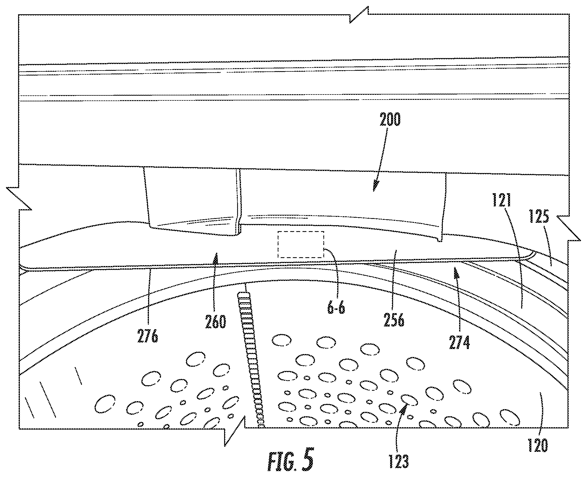
[0014] FIG. 5 provides a top, perspective view of a portion of a washing machine appliance, including a textured agitation panel, according to exemplary embodiments of the present disclosure.
[0015] FIG. 6A provides a magnified perspective of an upper surface of the textured agitation panel at the region 6-6 of FIG. 5 according to some exemplary embodiments of the present disclosure.
[0016] FIG. 6B provides a magnified perspective of an upper surface of the textured agitation panel at the region 6-6 of FIG. 5 according to other exemplary embodiments of the present disclosure.
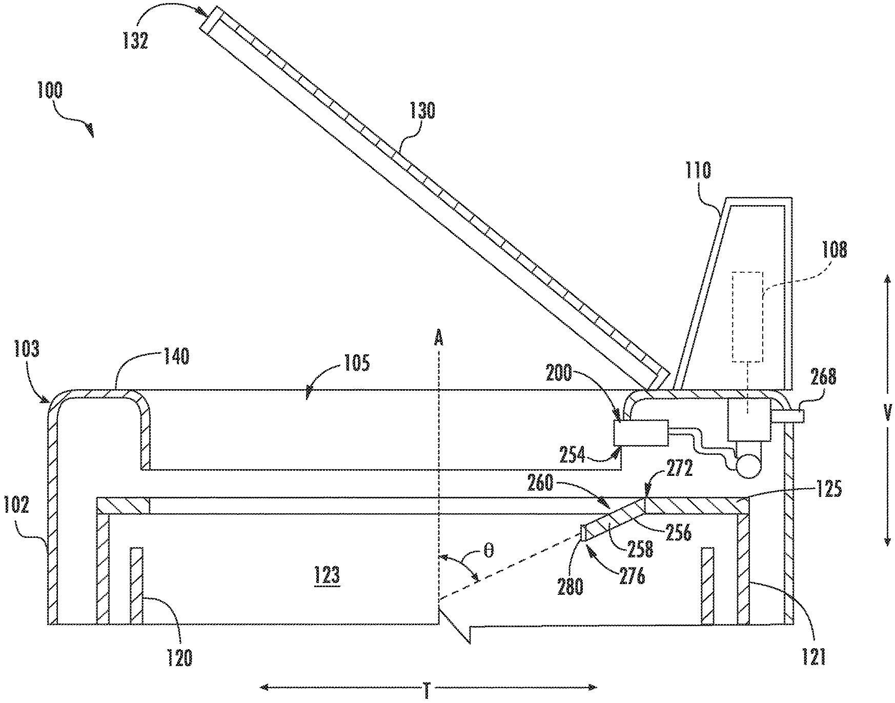
[0017] FIG. 7 provides a cross-sectional, side schematic view of an upper portion of a washing machine appliance according to certain exemplary embodiments of the present disclosure.
[0018] FIG. 8 provides a top, perspective view of a portion of a washing machine appliance, including a textured agitation panel, according to exemplary embodiments of the present disclosure.
DETAILED DESCRIPTION
[0019] Reference now will be made in detail to embodiments of the invention, one or more examples of which are illustrated in the drawings. Each example is provided by way of explanation of the invention, not limitation of the invention. In fact, it will be apparent to those skilled in the art that various modifications and variations can be made in the present invention without departing from the scope or spirit of the invention. For instance, features illustrated or described as part of one embodiment can be used with another embodiment to yield a still further embodiment. Thus, it is intended that the present invention covers such modifications and variations as come within the scope of the appended claims and their equivalents.
[0020] It is noted that, for the purposes of the present disclosure, the terms "includes" and "including" are intended to be inclusive in a manner similar to the term "comprising." Similarly, the term "or" is generally intended to be inclusive (i.e., "A or B" is intended to mean "A or B or both"). The terms "upstream" and "downstream" refer to the relative flow direction with respect to fluid flow in a fluid pathway. For example, "upstream" refers to the flow direction from which the fluid flows, and "downstream" refers to the flow direction to which the fluid flows.
[0021] Turning now to the figures, FIGS. 1 and 2 illustrate an exemplary embodiment of a vertical axis washing machine appliance 100. In FIG. 1, a lid or door 130 is shown in a closed position. In FIG. 2, door 130 is shown in an open position. Washing machine appliance 100 generally defines a vertical direction V, a lateral direction L, and a transverse direction T, each of which is mutually perpendicular, such that an orthogonal coordinate system is generally defined.
[0022] While described in the context of a specific embodiment of vertical axis washing machine appliance 100, using the teachings disclosed herein it will be understood that vertical axis washing machine appliance 100 is provided by way of example only. Other washing machine appliances having different configurations, different appearances, or different features may also be utilized with the present subject matter as well.
[0023] As shown, washing machine appliance 100 has a cabinet 102 that extends between a top portion 103 and a bottom portion 104 along the vertical direction V. A wash basket 120 is rotatably mounted within cabinet 102. A motor (not shown) is in mechanical communication with wash basket 120 to selectively rotate wash basket 120 about a rotation axis A (FIG. 7) (e.g., during an agitation or a rinse cycle of washing machine appliance 100). In some embodiments, the rotation axis A is parallel to the vertical direction V. Wash basket 120 is received within a wash tub 121 and defines a wash chamber 123 for receipt of articles for washing. The wash tub 121 holds wash and rinse fluids for agitation in wash basket 120 within wash tub 121. An agitator or impeller (not shown) may extend into wash basket 120 (e.g., within wash chamber 123) and may also be in mechanical communication with the motor. In some such embodiments, the impeller assists agitation of articles disposed within wash basket 120 during operation of washing machine appliance 100.
[0024] In some embodiments, cabinet 102 of washing machine appliance 100 has a top panel 140. Top panel 140 defines an opening 105 that permits user access to wash basket 120 of wash tub 121. Door 130, rotatably mounted to top panel 140, permits selective access to opening 105; in particular, door 130 selectively rotates between the closed position shown in FIG. 1 and the open position shown in FIG. 2. In the closed position, door 130 inhibits or otherwise restricts access to wash basket 120. Conversely, in the open position, a user is permitted access wash basket 120 through the opening 105 of top panel 140. In optional embodiments, a window 136 in door 130 permits viewing of wash basket 120 when door 130 is in the closed position (e.g., during operation of washing machine appliance 100). Door 130 may also include a handle 132 that, for instance, a user may pull or lift when opening and closing door 130. Further, although door 130 is illustrated as mounted to top panel 140, alternatively, door 130 may be mounted to cabinet 102 or any other suitable support.
[0025] In certain embodiments, a control panel 110 with at least one input selector 112 (FIG. 1) extends from top panel 140. Control panel 110 and input selector 112 collectively may form a user interface input for operator selection of machine cycles and features. A display 114 of control panel 110 indicates selected features, operation mode, a countdown timer, or other items of interest to appliance users regarding operation.
[0026] In exemplary embodiments, operation of washing machine appliance 100 is controlled by a controller or processing device 108 that is operatively coupled to control panel 110 for user manipulation to select washing machine cycles and features. In response to user manipulation of control panel 110, controller 108 operates the various components of washing machine appliance 100 to execute selected machine cycles and features.
[0027] Controller 108 may include a memory (e.g., non-transitive media) and microprocessor, such as a general or special purpose microprocessor operable to execute programming instructions or micro-control code associated with a cleaning cycle. The memory may represent random access memory such as DRAM, or read only memory such as ROM or FLASH. In one embodiment, the processor executes programming instructions stored in memory. The memory may be a separate component from the processor or may be included onboard within the processor. Alternatively, controller 100 may be constructed without using a microprocessor (e.g., using a combination of discrete analog or digital logic circuitry, such as switches, amplifiers, integrators, comparators, flip-flops, AND gates, and the like) to perform control functionality instead of relying upon software. Control panel 110 and other components of washing machine appliance 100 may be in communication with controller 108 via one or more signal lines or shared communication busses.
[0028] During operation of washing machine appliance 100, laundry items are loaded into wash basket 120 through opening 105, and a washing operation is initiated through operator manipulation of input selectors 112. Wash basket 120 is filled with a volume of liquid, such as water and detergent or other fluid additives, via a fluid dispenser 200. One or more valves can be controlled by washing machine appliance 100 to provide for filling wash basket 120 to the appropriate level for the mass or volume of articles being washed or rinsed. By way of example for certain wash modes or operations, once wash basket 120 is properly filled with fluid, the contents of wash basket 120 can be agitated (e.g., with an impeller as discussed previously) for washing of laundry items in wash basket 120.
[0029] After the agitation phase of the wash cycle is completed, wash basket 120 can be drained. Laundry articles can then be rinsed by again adding fluid (e.g., water) to wash basket 120 depending on the specifics of the cleaning cycle or washing operation selected by a user. The impeller may again provide agitation within wash basket 120. One or more spin cycles also may be used. In particular, a spin cycle may be applied after the wash cycle or after the rinse cycle to wring wash fluid from the articles being washed. During a spin cycle, wash basket 120 is rotated at relatively high speeds. After articles disposed in wash basket 120 are cleaned or washed, the user can remove the articles from wash basket 120 (e.g., by reaching into wash basket 120 through opening 105).
[0030] Referring now generally to FIGS. 2 through 4, fluid dispenser 200 will be described in more detail. Although the discussion below refers to the exemplary embodiment of fluid dispenser 200, one skilled in the art will appreciate that the features and configurations described may be used for other fluid dispensers in other washing machine appliances as well. For example, fluid dispenser 200 (e.g., an additional or alternative fluid dispenser 200) may be positioned elsewhere on cabinet 102, as illustrated in FIG. 2. Additionally or alternatively, fluid dispenser 200 may have a different shape or chamber configuration and may dispense water, detergent, or other additives. Other variations and modifications of the exemplary embodiment described below are possible, and such variations are contemplated as within the scope of the present disclosure.
[0031] In particular, although illustrated at a rear portion 142 of top panel 140, it is understood that additional or alternative embodiments may include a fluid dispenser 200 at one or more other locations above wash chamber 123. As an example, a fluid dispenser 200 for directing wash fluid (e.g., water or wash additive) to tub 121 may be positioned at a front portion 144 of top panel 140 (e.g., opposite from the opening 105 and a hinge the door 130 along the transverse direction T). As another example, a fluid dispenser 200 for directing wash fluid (e.g., water or wash additives) to tub 121 may be positioned at a first side portion 146 or a second side portion 148 of top panel 140 (e.g., a lateral end of the opening 105). Moreover, alternative embodiments may include configurations of a fluid dispenser that are not mounted to top panel 140 at all, but are instead secured to another portion of cabinet 102.
[0032] In exemplary embodiments, fluid dispenser 200 is a box or enclosure (e.g., having a substantially rectangular cross-section) that defines a top 202 and a bottom 204 spaced apart along the vertical direction V, as shown. Fluid dispenser 200 may also define a front side 206 and a back side 208 spaced apart along the transverse direction T (FIG. 2). As shown in FIGS. 2 and 3, fluid dispenser 200 may be mounted underneath top panel 140 of cabinet 102 such that front side 206 is visible inside opening 105. More specifically, fluid dispenser 200 may be mounted to top panel 140 using a plurality of mounting features 210 that may, for example, be configured to receive mechanical fasteners. One skilled in the art will appreciate that fluid dispenser 200 may be mounted in other locations and use other mounting means according to alternative exemplary embodiments.
[0033] Fluid dispenser 200 may define a mixing chamber 220 configured to receive one or more additive compartments. For example, according to the illustrated embodiment, mixing chamber 220 may be configured to slidably receive a detergent compartment 222 and a softener compartment 224. Compartments 222, 224 are slidably connected to the mixing chamber 220 using slides 226 and are connected to a front panel 228 of fluid dispenser 200. In this manner, a user may pull on front panel 228 to slide compartments 222, 224 along the transverse direction T. Once extended, detergent compartment 222 and softener compartment 224 may be conveniently filled with detergent and softener, respectively. Front panel 228 may be then be pushed back into mixing chamber 220 before a wash cycle begins.
[0034] Although the illustrated embodiment shows detergent compartment 222 and softener compartment 224 slidably received in mixing chamber 220 for receiving wash additives, one skilled in the art will appreciate that different configurations are possible in alternative exemplary embodiments. For example, more compartments may be used, and the compartments may be accessed by a lid instead of sliding out of mixing chamber 220. Alternatively, mixing chamber 220 may draw wash additives from a separate storage container such that sliding compartments 222, 224 are not needed. Other configurations of mixing chamber 220 and compartments 222, 224 are also possible and within the scope of the present disclosure.
[0035] In some embodiments, fluid dispenser 200 further includes a plurality of valves configured to supply hot and cold water to mixing chamber 220 or directly to wash tub 121. For example, according to the illustrated embodiment, a plurality of apertures may be defined on top 202 of mixing chamber 220 for receiving water. Each aperture may be in fluid communication with a different portion of the mixing chamber 220. A plurality of valve seats may be positioned over top of each of those apertures to receive a valve that controls the flow of water through each aperture.
[0036] Water inlets may be placed in fluid communication with each of valve seats 234, 236, 238, 240. More specifically, a hot water inlet 244 may be connected to a hot water supply line and a cold water inlet 246 may be connected to a cold water supply line. According to the illustrated embodiments, each water inlet 244, 246 includes a threaded male adapter configured for receiving a threaded female adapter from a conventional water supply line. However, any other suitable manner of fluidly connecting a water supply line and water inlets 244, 246 may be used. For example, each water supply line and water inlets 244, 246 may have copper fittings that may be sweated together to create a permanent connection.
[0037] Notably, hot water inlet 244 is in direct fluid communication with first valve seat 234. However, in exemplary embodiments, washing machine appliance 100 uses cold water for multiple purposes, and thus cold water inlet is in fluid communication with a cold water manifold 248. Cold water manifold 248 may be a cylindrical pipe that extends along the lateral direction from second valve seat 236 to fourth valve seat 240. In this manner, cold water manifold 248 places valve seats 236, 238, 240 in fluid communication with cold water inlet 246.
[0038] Each of valve seats 234, 236, 238, 240 may be configured to receive a water valve 252 for controlling the flow of water through a corresponding aperture into mixing chamber 220. Water valve 252 may be, for example, a solenoid valve that is electrically connected to controller 108. However, any other suitable water valve may be used to control the flow of water. Controller 108 may selectively open and close water valves 252 to allow water to flow from hot water inlet 244 through first valve seat 234 and from cold water manifold 248 through one or more of second valve seat 236, third valve seat 238, and fourth valve seat 240.
[0039] Fluid dispenser 200 may further include one or more nozzles for directing wash fluid, such as water or a mixture of water and at least one fluid additive (e.g., detergent, fabric softener, or bleach) into wash tub 121 from fluid dispenser 200. For example, when second valve seat 236 is open, water may flow from cold water inlet 246 through cold water manifold 248 and second valve seat 236 into detergent compartment 222. Water may mix with detergent placed in detergent compartment 222 to create wash liquid to be dispensed into wash tub 121.
[0040] In certain embodiments, a nozzle or fluid outlet 254 is positioned on the bottom of detergent compartment 222 or on the bottom of mixing chamber 220 to dispense the wash fluid into wash tub 121. In some embodiments, fluid dispenser 200 includes four nozzles associated with valves seats 234, 236, 238, 240, respectively. However, it will be understood that different nozzle configurations may be used in additional or alternative exemplary embodiments. For example, one or more nozzles may be positioned on a bottom of mixing chamber 220 near wash tub 121 or directly on wash tub 121. It is understood that nozzles could be positioned in other locations as well.
[0041] As discussed herein, in some situations, a user may wish to cause the flow of water separate from the flows associated with typical wash cycles. For example, a user may wish to obtain water for use when pretreating articles on a textured agitation panel 256, as discussed herein. The user may thus utilize a suitable input selector 112 or other dedicated input to cause water to be flowed on-demand and independently of the typical wash cycles of the washing machine appliance 100.
[0042] Turning now to FIGS. 5 through 8, various views are provided of portions of washing machine appliance 100, including fluid dispenser 200, according to exemplary embodiments of the present disclosure.
[0043] As shown, washing machine appliance 100 includes a tub cover 125 that is attached or fixed to tub 121. In particular, tub cover 125 may be fixed to a top portion of tub 121 and held above wash basket 120. One or more adhesives or mechanical fasteners (e.g., clips, prongs, screws, etc.) may be provided between tub cover 125 and tub 121 such that tub cover 125 is supported on, or held in place relative to, tub 121.
[0044] In some embodiments, a textured agitation panel 256 generally extends from tub cover 125 (e.g., above at least a portion of wash basket 120). As an example, textured agitation panel 256 may be formed on (e.g., as part of) tub cover 125. As another example, textured agitation panel 256 may be separately attached to tub cover 125 (e.g., via a suitable adhesive or mechanical fastener). When assembled, textured agitation panel 256 may generally extend toward wash chamber 123 defined by wash basket 120 (e.g., along the generally radial or downward path). In particular, textured agitation panel 256 extends from a proximal end 272 on tub cover 125 to a distal end 274 such that the distal end 274 is closer to wash chamber 123 and a proximal end 272. In some such embodiments, textured agitation panel 256 is angled or sloped downward from the proximal end 272 to the distal end 274 such that a bottom lip 276 is formed along the distal end 274.
[0045] Moreover, textured agitation panel 256 may be positioned between top panel 140 and wash basket 120. Textured agitation panel 256 may be positioned at a predetermined location about the opening 105. When assembled, textured agitation panel 256 may be located below or directly beneath the footprint of the door 130 in the closed position. A user may thus access textured agitation panel 256 (e.g., when the door 130 is in the open position).
[0046] Textured agitation panel 256 includes a substrate 258 and an upper surface 260. As shown, upper surface 260 generally faces opening 105 (e.g., toward a region thereabove). The user may thus view and access upper surface 260 when the door 130 is in the open position. In some embodiments, substrate 258 and upper surface 260 are mounted to tub cover 125 at a fixed position within cabinet 102.
[0047] In some embodiments, one or more elevated ridges 262 are defined at upper surface 260. For instance, a plurality of elevated ridges 262 may be integrally formed (e.g., as a unitary monolithic member) on substrate 258. Additionally or alternatively, a separable panel fixed to substrate 258 (e.g., via one or more suitable adhesives or mechanical fasteners) may define the elevated ridges 262. In some embodiments, upper surface 260 is formed as a nonpermeable surface (e.g., as illustrated in FIGS. 6A and 6B) such that liquids (e.g., water or wash fluid) are unable to pass through upper surface 260 and substrate 258. In alternative embodiments, textured agitation panel 256, including upper surface 260, define a plurality of permeable apertures 278 (e.g., as illustrated in FIG. 8) extending along the vertical direction V such that a liquid (e.g., water or wash fluid) is permitted to pass through upper surface 260 and substrate 258 without flowing to or past bottom lip 276.
[0048] When assembled, elevated ridges 262 may extend from substrate 258 or the remaining portion of upper surface 260 such that a user may scrub clothing more articles across the elevated ridges 262 (e.g., for the removal of stains from such articles). Optionally, the elevated ridges 262 may extend to a suitable height or distance (e.g., from the remaining portion of upper surface 260) between 0.1 inch and 0.5 inch. Moreover, the elevated ridges 262 may be formed to any suitable shape or design. As an example, and as illustrated in FIG. 6A, each ridge 262 may be formed as an isolated protrusion 264. Multiple protrusions 264 may be formed in, for instance, parallel wave pattern. As another example, and as illustrated in FIG. 6B, each ridge 262 may be formed as a corrugated crest 266, defining separate channels between adjacent ridges 262.
[0049] In optional embodiments, one or more pieces of a metallic trim 280 provided on a portion of textured agitation panel 256. For instance, metallic trim 280 may be mounted to the distal end 274 of textured agitation panel 256. In some such embodiments, metallic trim 280 extends along bottom lip 276 of textured agitation panel 256. In optional embodiments, textured agitation panel 256 is formed from an elastic or resilient polymer to which the metallic trim 280 is secured (e.g., via a suitable adhesive or mechanical fastener, such as an interference fit or cramp forms between metallic trim 280 and the substrate 258). Metallic trim may be provided as any suitable metal (e.g., stainless steel, aluminum, etc.) and may include a surface finish that is substantially smooth [e.g., defines a surface roughness (Ra) measurement that is greater than 3.2 .mu.m] and prevents abrasions against articles within wash chamber 123.
[0050] Turning especially to FIG. 7, in exemplary embodiments, textured agitation panel 256 extends at an angle from (e.g., directly from) an upper portion of tub cover 125. For instance, at least a portion of textured agitation panel 256 (e.g., upper surface 260) may extend at or otherwise define a non-parallel angle .theta. relative to the vertical direction V. Furthermore, textured agitation panel 256 may pass beneath opening 105 and generally extend radially inward (e.g., toward the rotation axis A of basket 120).
[0051] In some embodiments, textured agitation panel 256, including substrate 258, is attached or fixed to tub cover 125 directly. As an example, textured agitation panel 256 may be integrally formed (e.g., as a unitary monolithic unit) with tub cover 125. As another example, textured agitation panel 256 may be directly attached to tub cover 125 by one or more suitable adhesives or mechanical fasteners. Alternatively, textured agitation panel 256 may be indirectly attached to tub cover 125 through one or more intermediate members mounted within cabinet 102 between tub cover 125 and tub 121.
[0052] In some embodiments, fluid dispenser 200 is positioned above (e.g., directly above) at least a portion of textured agitation panel 256. In particular, fluid dispenser 200 may be mounted above upper surface 260. A fluid outlet 254 of fluid dispenser 200 may be directed toward upper surface 260. Water or wash fluid dispensed from fluid outlet 254 flows along the path defined by upper surface 260. In other words, fluid outlet 254 is positioned upstream from upper surface 260. As described above, fluid dispenser 200, including fluid outlet 254, is provided downstream from one or more fluid sources, such as water source 268 or a mixing chamber 220. During use, fluid dispenser 200 may thus selectively flow one or more fluids across textured agitation panel 256. In particular wash fluids may flow over upper surface 260 and across the elevated ridges 262 (FIGS. 6A and 6B) before flowing to tub 121 or wash basket 120. Advantageously, the wash fluid flowing over textured agitation panel 256 may be utilized when scrubbing articles thereon and, for example, further assist in the removal of stains. Moreover, the wash fluid may regularly clean textured agitation panel 256, preventing stains, mold, or mildew from accumulating on textured agitation panel 256.
[0053] This written description uses examples to disclose the invention, including the best mode, and also to enable any person skilled in the art to practice the invention, including making and using any devices or systems and performing any incorporated methods. The patentable scope of the invention is defined by the claims, and may include other examples that occur to those skilled in the art. Such other examples are intended to be within the scope of the claims if they include structural elements that do not differ from the literal language of the claims, or if they include equivalent structural elements with insubstantial differences from the literal languages of the claims.
* * * * *
D00000
D00001
D00002
D00003
D00004
D00005
D00006
D00007
D00008
XML
uspto.report is an independent third-party trademark research tool that is not affiliated, endorsed, or sponsored by the United States Patent and Trademark Office (USPTO) or any other governmental organization. The information provided by uspto.report is based on publicly available data at the time of writing and is intended for informational purposes only.
While we strive to provide accurate and up-to-date information, we do not guarantee the accuracy, completeness, reliability, or suitability of the information displayed on this site. The use of this site is at your own risk. Any reliance you place on such information is therefore strictly at your own risk.
All official trademark data, including owner information, should be verified by visiting the official USPTO website at www.uspto.gov. This site is not intended to replace professional legal advice and should not be used as a substitute for consulting with a legal professional who is knowledgeable about trademark law.