Oxidation Resistant Coating And Methods Of Manufacturing Thereof
Humphry-Baker; Samuel A. ; et al.
U.S. patent application number 16/088998 was filed with the patent office on 2020-04-30 for oxidation resistant coating and methods of manufacturing thereof. The applicant listed for this patent is Imperial Innovations Limited. Invention is credited to Samuel A. Humphry-Baker, William E. Lee.
| Application Number | 20200131616 16/088998 |
| Document ID | / |
| Family ID | 56027607 |
| Filed Date | 2020-04-30 |
| United States Patent Application | 20200131616 |
| Kind Code | A1 |
| Humphry-Baker; Samuel A. ; et al. | April 30, 2020 |
OXIDATION RESISTANT COATING AND METHODS OF MANUFACTURING THEREOF
Abstract
There is described a method of forming an oxidation resistant coating on a cermet comprising tungsten carbide, tungsten boride, or boron carbide and a metallic binder material. The method comprises exposing the cermet to silicon in the presence of an activator to form a mixture, exposing the mixture to an inert gas, and heating the mixture to a temperature T for a time t, thereby forming a coating on the cermet.
| Inventors: | Humphry-Baker; Samuel A.; (London, GB) ; Lee; William E.; (London, GB) | ||||||||||
| Applicant: |
|
||||||||||
|---|---|---|---|---|---|---|---|---|---|---|---|
| Family ID: | 56027607 | ||||||||||
| Appl. No.: | 16/088998 | ||||||||||
| Filed: | March 29, 2017 | ||||||||||
| PCT Filed: | March 29, 2017 | ||||||||||
| PCT NO: | PCT/GB2017/050879 | ||||||||||
| 371 Date: | September 27, 2018 |
| Current U.S. Class: | 1/1 |
| Current CPC Class: | C23C 10/06 20130101; C22C 29/062 20130101; C23C 10/34 20130101; C22C 29/14 20130101; G21F 1/08 20130101; C23C 10/44 20130101; C23C 10/08 20130101; C22C 29/08 20130101 |
| International Class: | C23C 10/44 20060101 C23C010/44; C23C 10/08 20060101 C23C010/08 |
Foreign Application Data
| Date | Code | Application Number |
|---|---|---|
| Mar 30, 2016 | GB | 1605361.3 |
Claims
1. A method of forming an oxidation resistant coating on a cermet comprising tungsten carbide, tungsten boride, or boron carbide and a metallic binder material, the method comprising the steps of: (a) exposing the cermet to silicon in the presence of an activator to form a mixture; (b) exposing the mixture to an inert gas; and (c) heating the mixture to a temperature T for a time t, thereby forming a coating on the cermet.
2. The method according to claim 1, wherein the cermet comprises 10 wt. % of the metallic binder.
3. The method according to claim 1, wherein the metallic binder material comprises iron, cobalt, nickel, chromium or mixtures thereof.
4. The method according to claim 1, wherein the metallic binder is in the form of a matrix.
5. The method according to claim 1, wherein the activator comprises a halide salt.
6. The method according to claim 5, wherein the halide salt comprises sodium fluoride, sodium chloride, ammonium chloride or potassium tetrafluoroborate.
7. The method according to claim 1, wherein T is in the range from 700 to 1200.degree. C.
8. The method according to claim 1, wherein T is 1000.degree. C.
9. The method according to claim 1, wherein t is from 0.1 to 10 hours.
10. The method according to claim 1, wherein t is from 1 to 4 hours.
11. The method according to claim 1, wherein the inert gas comprises argon and 5 wt % hydrogen.
12. The method according to claim 1, wherein the thickness of the coating formed is from 5 to 500 .mu.m.
13. The method according to claim 1, wherein the thickness of the coating formed is from 40 to 70 .mu.m.
14. The method according to claim 1, further comprising a cooling step (d) to cool the coating and the cermet from temperature T.
15. The method according to claim 14, wherein the coating and cermet are cooled at a rate of from 5 to 10.degree. C. per minute.
16. The method of claim 1, which method comprises a pack cementation process.
17. The method of claim 1, wherein the mixture in step (a) is formed by packing silicon and the activator around the cermet.
18. A tungsten carbide, tungsten boride, or boron carbide cermet comprising a coating formed in accordance with the method of claim 1.
19. A cermet comprising tungsten carbide, tungsten boride, or boron carbide, a metallic binder material, and an oxidation resistant silicide coating, wherein the surface of the coating substantially consists of silicides of the metallic binder material.
20. A method of forming an oxidation resistant coating on a cermet comprising tungsten carbide, tungsten boride, or boron carbide and a metallic binder material, the method comprising the steps of: a) exposing the cermet to silicon; and b) heating the mixture to a temperature T for a time t, thereby forming a coating on the cermet.
21. A method according to claim 20, wherein exposing the cermet to silicon comprises exposing the cermet to a vapour including a precursor containing silicon.
Description
CROSS-REFERENCE TO RELATED APPLICATIONS
[0001] This application claims priority to, and the benefit of, PCT Application No. PCT/GB/2017/050879, filed on Mar. 29, 2017 and entitled "Oxidation Resistant Coating and Methods of Manufacturing Thereof," which claims priority to, and the benefit of, United Kingdom Patent Application No. 1605361.3, filed on Mar. 30, 2016 and entitled "Oxidation Resistant Coating and Methods of Manufacturing Thereof."
TECHNICAL FIELD
[0002] The present invention relates to a method for forming oxidation resistant coatings for tungsten carbide, tungsten boride, and boron carbide cermets (composites).
BACKGROUND
[0003] Nuclear fusion could provide unlimited energy that is carbon-zero and free from long-lived nuclear waste and threat of accident. With this in mind, industry is focusing on development of fusion reactors, for example tokamak reactors, stellarators or inertially confined fusion reactors. Development of such fusion reactors promises a route to fusion energy that is cheaper and faster than conventional technologies. One aspect of industrial focus is the development of advanced materials in some key areas.
[0004] A particularly pressing materials challenge for compact spherical tokamak reactors is in developing more efficient neutron shielding materials than in conventional reactors (e.g. in the central column or the divertor of tokamak reactors). It has been found that tungsten carbide, tungsten boride, and boron carbide composites could be excellent shields for high-energy neutrons.
[0005] Oxidation resistance of shielding materials is an important property of reactor materials for accident safety. In particular, if a reactor were to break-open, its walls would be exposed to a rapid influx of air, thus inducing surface oxidation and production of tungsten or boron oxides.
[0006] At very high reactor temperatures, tungsten and boron oxides become volatile, which could release hazardous transmutation products into the atmosphere.
[0007] Coatings on tungsten carbide composites (tungsten carbide cermets, also known as "hardmetal") have been developed in other technological areas besides fusion reactors, where oxidation resistance is important, particularly in the machine tool industry. Generally, oxidation resistance can be improved by two basic means: (i) blending small additions of oxidation resistant powders, such as cubic carbides, into the bulk of the component during initial processing; or (ii) by coating the surface of the material with an oxidation resistant layer after the component has been made.
[0008] Oxidation resistant tungsten carbide, tungsten boride, or boron carbide composite coatings for use in fusion reactors should be capable of suppressing oxidation of the composite at high temperatures up to 1000.degree. C., which is a reasonable maximum operating temperature for a fusion reactor.
[0009] Typically, oxidation resistant coatings on tungsten carbide composites that are suitable for use at high temperatures are formed by diffusing boron into the surface. By doing so, boron-rich compounds are formed on the surface on the tungsten carbide composite. This process is known as boronisation. Boronised coatings are additionally advantageous because they provide improved surface hardness. However, the actual reduction in rate of oxidation of boronised coatings at high temperatures is quite limited. For this reason, more effective oxidation resistant coatings are needed.
[0010] It is therefore an object of the present invention to provide an improved oxidation resistant coating for tungsten carbide, tungsten boride, and boron carbide composites, capable of providing improved oxidation resistance at high temperatures, and a method of manufacturing said coatings.
[0011] The present invention relates to an improved oxidation resistant silicon-rich coating for tungsten carbide, tungsten boride, and boron carbide composites, capable of suppressing the formation and release of toxic oxides when exposed to oxidative conditions (e.g. in the event of the rupture of a nuclear reactor). It has been found that the coating according to the present invention oxidises at a rate which is approximately 3-4 orders of magnitude slower than non-coated materials and about 2-3 orders of magnitude slower than boronised materials, at temperatures up to 1200.degree. C. The present invention also relates to a method for producing the improved oxidation resistant silicon-rich coating.
SUMMARY OF INVENTION
[0012] The present invention relates to a method of forming an oxidation resistant coating on a cermet comprising tungsten carbide, tungsten boride, or boron carbide comprising a metallic binder material. The method comprises the steps of: (a) exposing the cermet to silicon in the presence of an activator to form a mixture; (b) exposing the mixture to an inert gas; and (c) heating the mixture to a temperature T for time t, thereby forming a coating on the cermet.
[0013] Exposing the mixture to an inert gas helps to prevent any unwanted chemical reactions from occurring during the formation of the oxidation resistant coating.
[0014] The metallic binder material may be in the form of a matrix. The metallic binder is homogenously dispersed and at high volume fractions forms a continuous network around the ceramic particles, while at low volume fractions it is semi-continuous or discontinuous. The metallic binder material of the cermet may comprise iron, cobalt, nickel, chromium or mixtures thereof. For example, the metallic binder material could be alloys comprising the aforementioned binder materials, such as iron-chromium, or nickel-cobalt alloys. It has been found that using iron or alloys thereof (e.g. iron-chromium) as the metallic binder material is preferable due to the resistance to becoming excessively radioactive under neutron exposure. In contrast, cobalt and nickel based metallic binders become strongly radioactive after only a short neutron exposure. It has been found that during the coating process the silicon reacts with iron to form iron silicide. The silicon reacts with the tungsten carbide, tungsten boride, or boron carbide to form tungsten silicide, tungsten silicide and boron silicide respectively.
[0015] As discussed above, the metallic binder is not limited to iron, and preferable metallic binder materials may comprise, for example, chromium, cobalt or nickel, which react with the silicon to form chromium silicide, cobalt silicide and nickel silicide respectively.
[0016] The metallic binder material may alternatively comprise any other period 4 transition metals, for example scandium, titanium, vanadium, manganese, copper, zinc, or mixtures thereof.
[0017] The cermet may comprise from 1 to 30 wt. % of the metallic binder material, preferably 5 to 30 wt. %, more preferably 5 to 15 wt. % and most preferably 10 wt. % of the metallic binder.
[0018] Improving oxidation resistance by siliconising a cermet in accordance with the method described herein is unexpected. Based on known coating methods for similar composites (e.g. boronisation of tungsten carbide composites), it would be expected that siliconising, for example, a tungsten carbide cermet comprising a metallic binder material, would provide a coating comprising tungsten silicide and the reaction product of the metallic binder material and silicon. It would also be expected that the tungsten silicide and reaction product of the metallic binder material and silicon would be present in amounts relative to the amount of tungsten carbide and metallic binder material respectively within the tungsten carbide cermet. Tungsten silicide has low oxidation resistance at the operating temperatures of a fusion reactor (typically between 400 to 1000.degree. C.), and therefore it would be an undesirable component on a coating designed for oxidation resistance.
[0019] Surprisingly, it has been found that even when the cermet comprises relatively low amounts of the metallic binder material (e.g. less than 40 wt. % of the metallic binder material), the coating formed on the surface of the cermet is substantially all the reaction product of the metallic binder and silicon, despite there being less than 30 wt. % of the metallic binder within the cermet at the start. Even more surprisingly, it has been found that siliconising a tungsten carbide cermet comprising even a 10 wt. % iron and 90 wt. % tungsten carbide in the cermet, in accordance with the method discussed herein, results in a coating where the surface comprises approximately 1 wt. % tungsten silicide and approximately 99% wt. % iron silicide (i.e. the coating surface comprises substantially all iron silicide). In other words, it has been found that there is a preferential segregation of iron silicide to the surface of the coating. This is likely to be the result of the silicon diffusing more rapidly through the binder metal than the ceramic particles.
[0020] A substantially pure iron silicide coating is advantageous because of the surprising and effective oxidation resistance it offers, even at temperatures as high as 1200.degree. C. The preferential segregation (de-mixing) of the iron silicide causing almost all the surface being occupied by iron silicide and almost no tungsten silicide presence is advantageous because tungsten silicide has a relatively low oxidation resistance. It is expected that preferential segregation (de-mixing) effects are observed when other metallic binders such as cobalt, nickel or chromium are used.
[0021] The activator used may be a halide salt. Preferably, the halide salt is sodium fluoride. The halide salt may alternatively be any other halide salt, for example sodium chloride, ammonium chloride, and potassium tetrafluoroborate.
[0022] The activator may be present in an amount within the range from 5 to 50 wt. % of the substrate. Most preferably, 20 wt. % of activator is used.
[0023] The mixture may optionally include an inert filler powder, e.g. aluminium oxide, silicon dioxide, and/or silicon carbide. Preferably, the inert filler powder is added during step (a).
[0024] The temperature of step (c) may be any temperature in the range from 700 to 1200.degree. C., preferably 800 to 1100.degree. C., more preferably 900 to 1000.degree. C. and most preferably 1000.degree. C.
[0025] The time t given in step (c) may be any time within the range from 0.1 to 10 hours, preferably from 1 to 8 hours, more preferably 2 to 6 hours, and most preferably 4 hours.
[0026] The inert gas may be an inert or reducing atmosphere. The inert gas may comprise hydrogen, nitrogen, helium, neon, argon, krypton, xenon, radon, or mixtures thereof. Preferably, the inert gas is a mixture of argon and hydrogen comprising an amount of argon within the range from 90 wt. % to 99 wt. % and an amount of hydrogen within the range from 1 to 10 wt. %. For example, the mixture may comprise 99 wt. % argon and 1 wt. % hydrogen, 98 wt. % argon and 2 wt. % hydrogen, etc. Most preferably, the concentration of the argon and hydrogen mixture is 95 wt % argon and 5 wt % hydrogen. It has been found that too much hydrogen (more than 10 wt. %) in the gas mixture can cause embrittlement of the cermet and coating if iron is used as the metallic binder.
[0027] The coating formed using the method described herein may have a thickness of from 5 to 500 .mu.m. It has been found that the lower limit of the thickness of the coating formed is set by the size of the particles within the cermet. The coating thickness should be at least several times the thickness of the size of the particles within the cermet. For example, where particle size is 1 to 2 .mu.m a coating thickness of at least 10 .mu.m should be obtained. A thicker coating may be needed if the cermet comprises larger particles, e.g. if the particle size is 10 .mu.m then a coating should have a minimum thickness of 100 .mu.m. Preferably the coating thickness is 10 to 100 .mu.m, more preferably 25 to 75 .mu.m, even more preferably 35 to 65 .mu.m. Most preferably, the coating formed using the method described herein has a thickness of 50 .mu.m. Different thicknesses may be obtained by varying time t and/or temperature T.
[0028] The method may further comprise a cooling step (d), wherein the coating and the cermet are cooled from temperature T. Preferably, the cooling step (d) cools the coating and the cermet at a rate of 1 to 15.degree. C. per minute, more preferably the cooling step (d) cools the coating and the cermet at a rate of 5 to 10.degree. C. per minute. Preferably, the cooling step (d) cools the coating and the cermet to an ambient temperature. It has been found that cooling the coating and the cermet in this way avoids breakage/cracking of the coating and/or the cermet during the cooling step.
[0029] The present invention also relates to a cermet comprising a coating formed in accordance with the method described herein.
BRIEF DESCRIPTION OF THE DRAWINGS
[0030] The method according to the present invention may be carried out in various ways and a preferred embodiment of a method of forming an oxidation resistant coating on a tungsten carbide, tungsten boride, or boron carbide cermet comprising a metallic binder in accordance with the present invention will now be described by way of example with reference to the accompanying figures, in which:
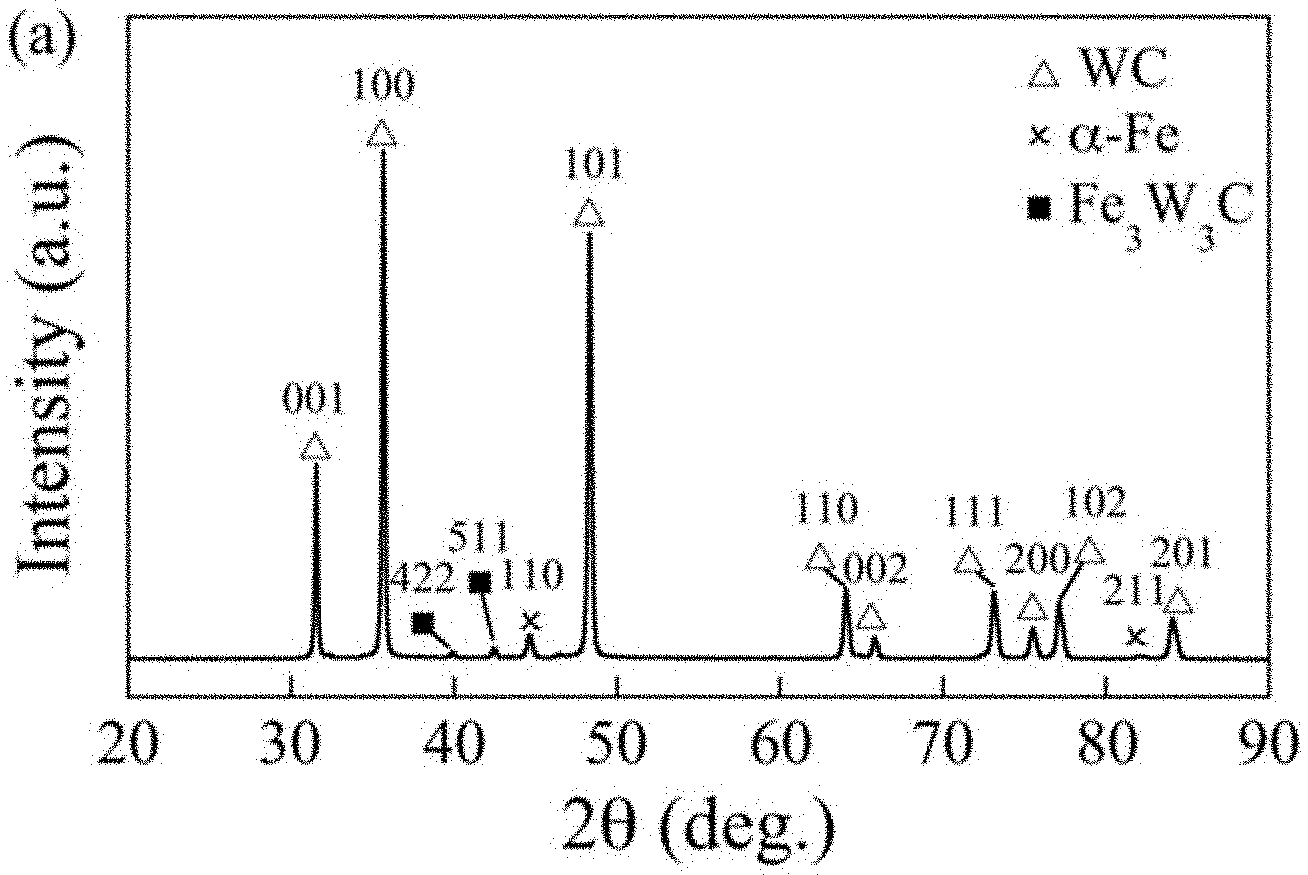
[0031] FIG. 1--Is an X-Ray Diffraction (XRD) pattern showing the phase composition of a tungsten carbide cermet comprising an iron binder material;
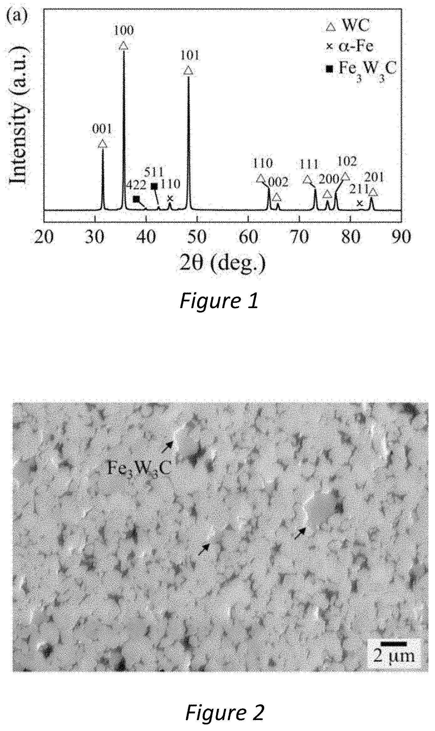
[0032] FIG. 2--Is a Scanning Electron Microscope (SEM) micrograph showing a typical morphology of a tungsten carbide cermet comprising an iron binder material;
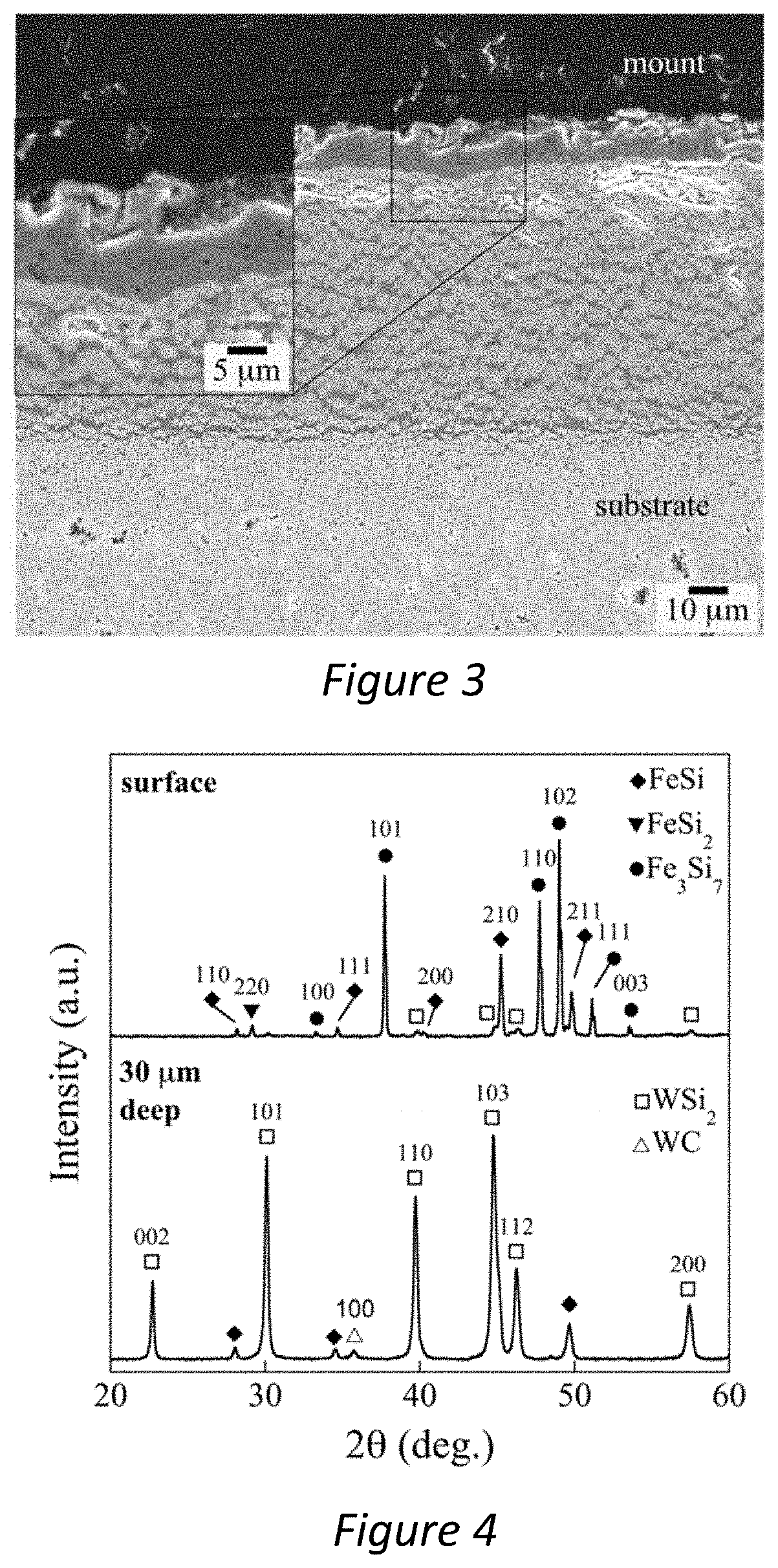
[0033] FIG. 3--Is an SEM image of a coating produced in accordance with the present invention;
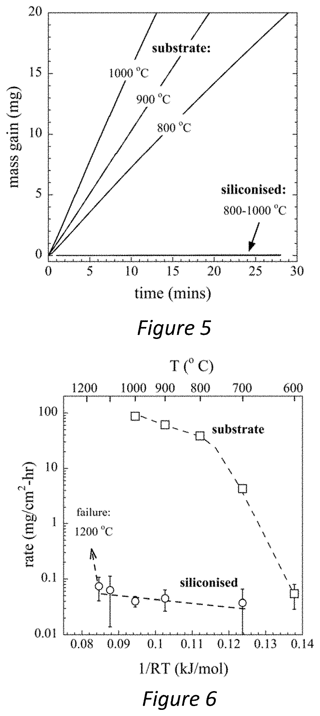
[0034] FIG. 4--Is an XRD pattern showing composition of a coating produced in accordance with the present invention on the surface of the coating and at 30 .mu.m deep in the coating;
[0035] FIG. 5--Is a chart comparing the oxidisation rate of untreated tungsten carbide cermets with tungsten carbide cermet with a coating produced in accordance with the present invention at varying temperatures;
[0036] FIG. 6--Is a chart comparing the oxidisation rate of coatings produced in accordance with the present invention and untreated tungsten carbide cermets;
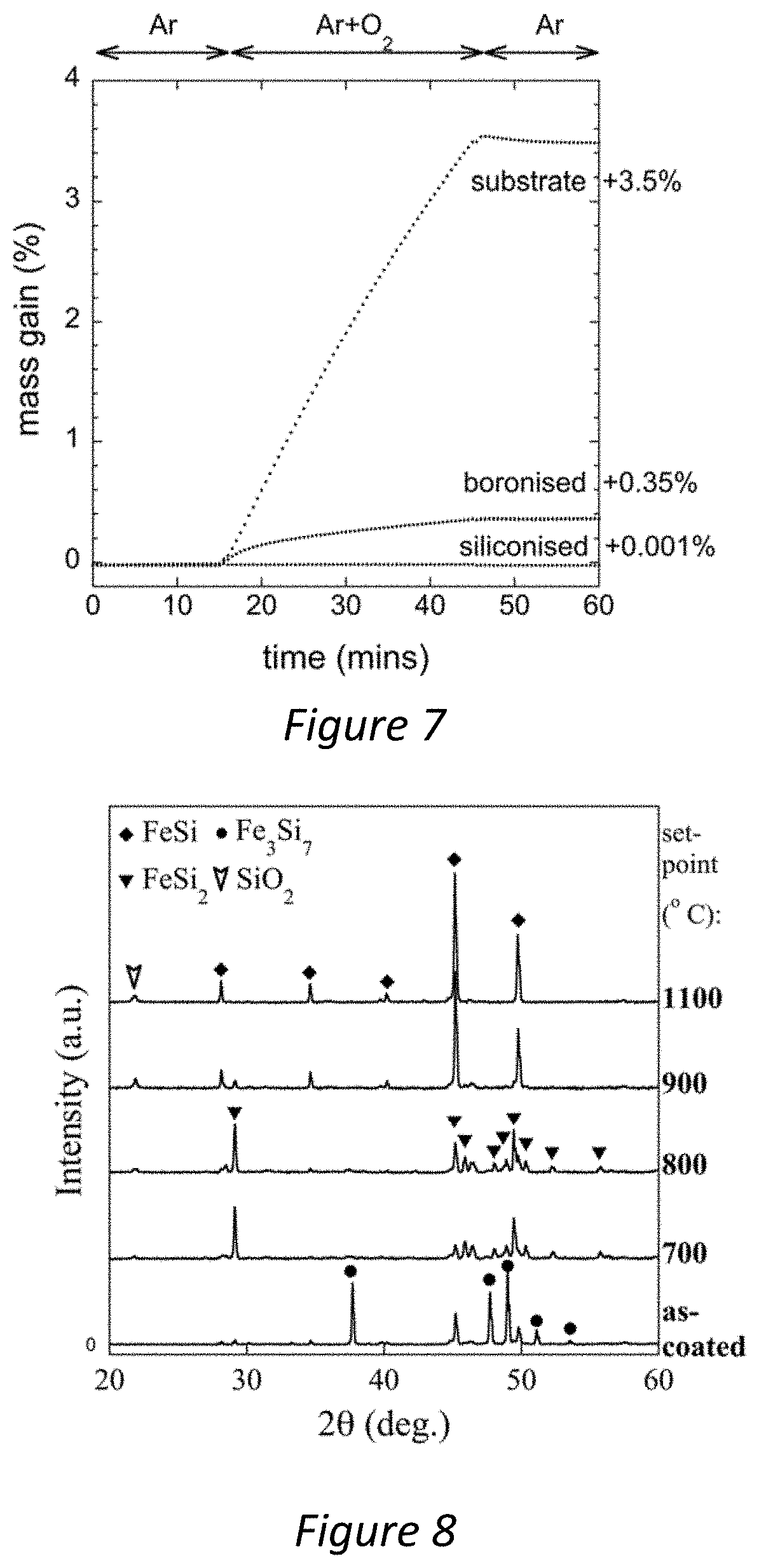
[0037] FIG. 7--A chart comparing oxidation resistance of a coating produced in accordance with the present invention with an untreated tungsten carbide cermet and a boronised tungsten carbide cermet;
[0038] FIG. 8--Is a set of XRD patterns that compare coatings produced in accordance with the present invention at temperatures varying between 700 and 1100.degree. C.;
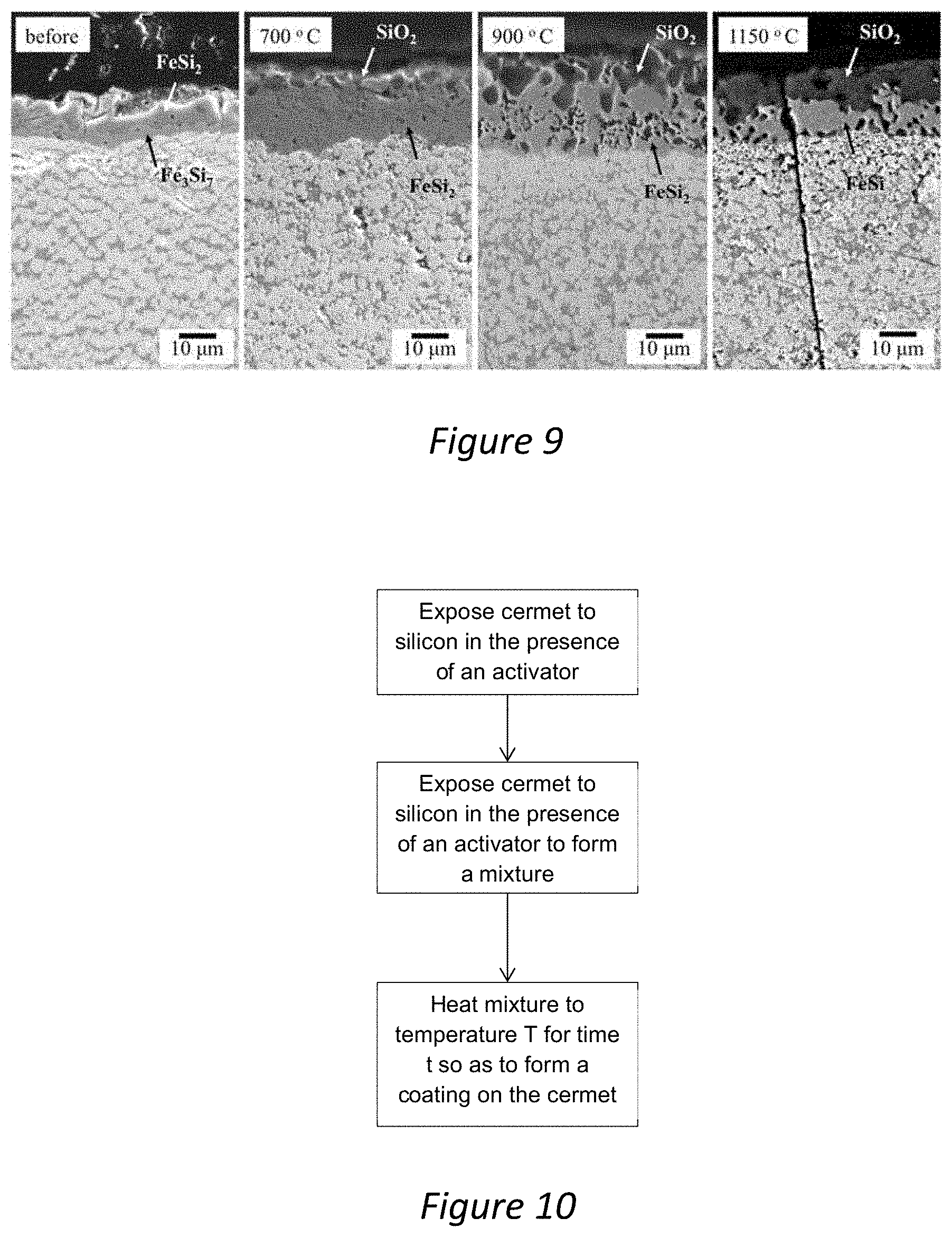
[0039] FIG. 9--Is a set of SEM micrographs showing cross-sections of a coating produced in accordance with the present invention after being exposed to various temperatures between 700 and 1150.degree. C.; and
[0040] FIG. 10--Is a flow chart showing steps forming a coating.
DETAILED DESCRIPTION
[0041] The following discussion relates to a method for producing an oxidation resistant coating via the siliconising of a tungsten carbide composite (cermet) of the type used as a shielding material inside a nuclear reactor, and more specifically, of the type used inside a compact spherical tokamak reactor. The advantages of the use of tungsten carbide composites in nuclear reactors, and the advantages of an oxidation resistant coating on said composites are discussed above. It should be understood that siliconised coatings of the type discussed herein are not limited for use inside a nuclear reactor, and may be useful for any other applications where oxidation resistant coatings are required, e.g. the machine tool industry.
[0042] The term "cermet" is used to indicate a structure that combines a metal with a ceramic, where the ceramic is in the form of particles, and the metal may form a continuous, semi-continuous or discontinuous network around the particles, thereby forming a matrix.
[0043] To fabricate siliconised coatings a "pack cementation" process is employed and described below. However, it should be noted that other routine techniques for depositing silicon could be used. For example, an alternative chemical vapour deposition (CVD) process such as a fluidised bed reactor (CVD-FBR) may be used, or a fused-slurry technique may be used.
General Method
[0044] An oxidation resistant silicon coating is produced on the surface of a tungsten carbide composite comprising a metallic binder material using the following method: [0045] (i) the tungsten carbide composite ("the part") is packed into a crucible containing silicon powder and an "activator" ("the pack"). The activator is typically a halide salt; [0046] (ii) inert gas is flowed over the crucible; [0047] (iii) the crucible is then heated to a set-point temperature and held for a few hours for coating growth to occur. This temperature is usually 1000.degree. C., but could be different; and [0048] (iv) the crucible and contents are cooled and the part removed from the pack. The cooling rate is typically 5 to 10.degree. C. per minute. Cooling the contents too rapidly may lead to breakage of the part due to an inhomogeneous temperature distribution.
[0049] Increasing the length of time the part is held in the pack at the set temperature, increases the thickness of the coating produced, and vice versa. Increasing the temperature also increases the thickness of the coating produced, and vice versa.
A. Method of Manufacture
[0050] 1. Coating Fabrication
[0051] Tungsten carbide (WC) composites (hereafter referred to as "the substrate" or "the cermet") were supplied by Sandvik Hard Materials Ltd. and had a nominal composition of 90 wt. % WC and 10 wt. % ferritic binder (hereinafter referred to as "WC-Fe").
[0052] A micrograph of a typical WC-Fe composite is shown in FIG. 2. In this particular material, the WC particles, shown in white, make up 90 wt. % of the structure, which is quite typical for these materials. The Fe makes up only 10 wt. % and appears black.
[0053] For pack cementation coating of the substrate, the powder pack consisted of two components: Silicon (Si) and Sodium Fluoride (NaF) powders (supplied by Alpha Aesar), of 99% and 99.5% purity, of mesh size 50 and 90, respectively. Powders were weighed in the weight ratio 80 Si:20 NaF, mixed in a mortar with a pestle and loaded into a lid-topped alumina crucible and packed around a pellet of dimensions 7.times.4.times.4 mm. The pack was heated to 1000.degree. C. in a tube furnace in flowing Ar-5% H.sub.2 gas and held isothermally for 4 hours. The average mass gain of the pellets was 15.4.+-.0.5 mg/cm.sup.2, and the coating thickness was 65.+-.9 .mu.m, as determined with a mass balance and digital micrometer with accuracies of .+-.0.1 mg and .+-.2 .mu.m respectively.
[0054] 2. Characterisation
[0055] The substrate material, as well as coated samples, were characterized by X-ray diffraction (XRD), using a PANalytical X'Pert powder diffractometer with a Copper (Cu) radiation source operated at 40 kV and 40 mA. Patterns were collected at a scan rate of 2.degree./min over a scan range of 20.degree.-90.degree. 2.theta.. The patterns were matched to ICDD Powder Diffraction Files (PDFs) and analyzed using the Rietveld method to determine the relative phase fractions and their lattice parameters, employing a pseudo-Voigt profile function. Scanning electron microscopy images were collected using a JSM 6010 SEM, operated in secondary electron imaging mode. To determine the chemical composition at points in the microstructure an Energy Dispersive X-ray (EDX) system was used.
[0056] 3. Oxidation Tests
[0057] For oxidation tests, samples were loaded into an alumina crucible inside a STA 449 F5 Jupiter Thermogravimetric Analyser (TGA). In each experiment, the sample was heated to the set-point at a rate of 20.degree. C./min in high purity argon, and held isothermally. Once the temperature stabilised, synthetic air (80% N.sub.2; 20% O.sub.2) was flowed over the sample at 100 ml/min for a set time interval of at least 30 minutes, after which the flow gas was switched back to Ar and cooled. Details of a similar procedure are given in a previous study: S. A. Humphry-Baker, W. E. Lee, Tungsten carbide is more oxidation resistant than tungsten when processed to full density, Scr. Mater. (2016).
[0058] To calculate the oxidation rate constant, the mass gain signal was normalised by the instantaneous sample surface area. The initial area was measured using a micrometer of accuracy.+-.0.002 mm--and for coated samples this was assumed constant, since the amount of oxide up-take was small. However, for uncoated samples the area reduction during oxidation was significant and calculated by assuming that the substrate (of density 14.1 g/cm.sup.3) recedes isotropically in all directions and that the mass gain upon formation of the oxide film is about 19.4%. This mass increase factor was calculated using the following equation:
f-WC+(1-f)-Fe+(2f+1/2)O.sub.2.fwdarw.(2f-1)-WO.sub.3+(1-f)-FeWO.sub.4+f-- CO.sub.2,
where f is the molar fraction of WC, which, is about f=0.72 for our WC-Fe samples (based on a nominal mass fraction of 0.9).
B. Results
[0059] 1. Microstructure of Coatings
[0060] FIGS. 1 and 2 show the phases and microstructure of the substrate before coating application. FIG. 1 shows an XRD pattern, which indicates there are three phases present: hexagonal WC (PDF 101-3982), ferritic .alpha.-Fe (1-1267) and a small quantity of cubic Fe.sub.3W.sub.3C phase (170-7470). FIG. 2 shows a representative SEM cross-sectional image, showing mainly WC grains in light grey and Fe binder in black. A small quantity of Fe.sub.3W.sub.3C, sometimes known as eta phase, is shown in dark grey, which is a reaction product from sintering under a sub-stoichiometric carbon content, due to narrow and carbon-rich two-phase region in WC-Fe cermets. Stereographic analysis reveals the WC grain size is 0.8.+-.0.12 .mu.m.
[0061] FIG. 3 shows an SEM cross-sectional image of the siliconised coating. The lower part of the FIG. 3 shows the substrate, which contains some small pores of a few .mu.m in diameter, which were typically observed in the region between 20 and 200 .mu.m from the substrate-coating interface. Above the substrate is the siliconised coating, which had a typical thickness of 65 .mu.m.+-.9 .mu.m--as measured using a micrometer on three nominally identical samples. The coating structure contains an outer crust, which appears in dark contrast. The inset of FIG. 3 shows a higher magnification image of the crust, revealing that the outer crust is made up of two layers of differing chemical composition.
[0062] FIG. 4 shows the phases present in the coating, via XRD patterns taken from the top surface of the coating (i.e. the specimen crust), and a pattern taken after the top 30 .mu.m of material was removed by mechanical polishing (i.e. bulk of the coating). The top surface material is made up almost exclusively of iron silicides, namely: FeSi, FeSi.sub.2, Fe.sub.3Si.sub.7, with a small amount of WSi.sub.2 (PDFs 192-3808, 20-0532, 35-0822 and 192-4516 respectively). Rietveld analysis revealed that their relative volume fractions are about 0.1 FeSi, 0.31 FeSi.sub.2, 0.58 Fe.sub.3Si.sub.7, and 0.01 WSi.sub.2. Thus the crust is predominantly iron-rich, with an iron-to-tungsten ratio about 500 times higher than in the substrate. By contrast, the bulk of the coating, as shown in the XRD pattern from a depth of 30 .mu.m, is made up of predominantly WSi.sub.2, with a smaller amount of FeSi.
[0063] 2. Oxidation Kinetics
[0064] The oxidation mass gain kinetics of the siliconised and substrate material are compared in FIG. 5, between 800 and 1,000.degree. C. Each thermogravimetry trace starts at the moment air is injected into the furnace, i.e. once the sample is already settled at the isothermal set-point. For the substrate, a large and monotonic mass gain begins at the instant that air is introduced. The oxidation rate increases with increasing temperature, reaching a total mass gain of 21, 30 and 42 mg after 20 mins at 800, 900, and 1,000.degree. C. respectively. By contrast, the siliconised specimens show mass gains of between about 0.01 and 0.02 mg over the same temperature interval, and thus the curves appear flat and superimposed on one another.
[0065] To allow more quantitative comparison, FIG. 6 compares the oxidation rate constants of the substrate and siliconised samples. Each data point represents the overall gradient of the mass gain signal, as determined using a least-squares linear fit, after any substrate surface area corrections are applied. The substrate shows rapid increase in oxidation rate over the temperature range 600-1000.degree. C., i.e. from about 0.04 to 90 mg/cm.sup.2-h. By comparison, the siliconised samples maintain very low oxidation rates of between 0.02 and 0.08 mg/cm.sup.2-h. The rate constants were 3 orders of magnitude lower than the substrate at the highest temperatures. As indicated by the error bars in FIG. 6, the rates of mass gain were close to the accuracy of the microbalance. The siliconised samples were stable up to 1150.degree. C., but failed at 1200.degree. C., which is close to the melting point of Fe.sub.3Si.sub.7 phase, which is 1209.degree. C.
[0066] FIG. 7 shows the typical oxidation behaviour of the siliconised material, vs. an un-coated substrate material, and a typical boronisation treatment coating that is common to industry. In this particular experiment all samples were heated to 1000.degree. C. In the case of the uncoated substrate, a large mass gain is shown at the instant air is flown over the sample. By comparison, boronised treatments show some improvement in oxidation rate, however, the siliconised coatings produced by the method described herein show almost complete suppression of oxidation, where the rate of mass gain is decreased by 3-4 orders of magnitude.
[0067] The siliconised coatings formed by the method described herein provide effective oxidation resistance over a range of temperatures. It has been established that at temperatures between 800.degree. C. and 1150.degree. C. the coatings are highly stable, and effective oxidation protection is expected at lower temperatures still. FIG. 6 shows data collected so far on the oxidation rates of the siliconised materials as compared to the uncoated WC-Fe substrate. There is a 3-4 order of magnitude improvement over a range of temperatures.
[0068] 3. Siliconised Oxide Layer Structure
[0069] FIG. 8 shows the phases present in the upper crust of the siliconised coatings, via XRD patterns of the specimen surface. Each pattern is taken from an oxidised sample after a 30 minute TGA test at various temperatures between 700 and 1100.degree. C.--such as those depicted in FIG. 5. The key feature to note is the emergence of SiO.sub.2, which was best-matched to the crystabollite-low phase (PDF 1-76-937), as demarked by the appearance of the (101) peak at 22 degrees 2.theta.. Further inspection of FIG. 7 reveals further key transitions occurring with increasing temperature in the iron silicide crust: firstly, at about 700-800.degree. C. there is a gradual conversion from predominantly Fe.sub.3Si.sub.7 in the as-coated condition to predominantly FeSi.sub.2. Next, above about 900.degree. C., the Fe.sub.3Si.sub.7 is replaced by FeSi, which is accompanied by a marked increase in the SiO.sub.2 peak intensity. In none of the XRD patterns was any evidence for iron oxide found.
[0070] FIG. 9 shows cross-sectional SEM micrographs of the oxidised samples at 700, 900 and 1150.degree. C., compared to the as-coated state. The upper-most part of the coating is shown, i.e. only the transition from the coating bulk to the outer crust--which are mostly WSi.sub.2+FeSi and FeSi.sub.2+Fe.sub.3Si.sub.7 respectively, in the case of as-coated samples. In all three oxidised samples, a thin layer of SiO.sub.2 is visible above the outermost iron silicide layer. The SiO.sub.2 thickness is uneven, and appears to penetrate into asperities in the outer iron silicide crust, in some cases forming encapsulated regions of SiO.sub.2 deep into the crust. Overall, the amount of SiO.sub.2 in the outer layer, relative to Fe.sub.xSi, increases with increasing temperature; at 1150.degree. C. the SiO.sub.2 penetrates well over half of the crust depth. This is in agreement with the increasing intensity of the (101) SiO.sub.2 peak in FIG. 8, and the increasing rate of mass gain in FIG. 7.
* * * * *
D00000
D00001
D00002
D00003
D00004
D00005
XML
uspto.report is an independent third-party trademark research tool that is not affiliated, endorsed, or sponsored by the United States Patent and Trademark Office (USPTO) or any other governmental organization. The information provided by uspto.report is based on publicly available data at the time of writing and is intended for informational purposes only.
While we strive to provide accurate and up-to-date information, we do not guarantee the accuracy, completeness, reliability, or suitability of the information displayed on this site. The use of this site is at your own risk. Any reliance you place on such information is therefore strictly at your own risk.
All official trademark data, including owner information, should be verified by visiting the official USPTO website at www.uspto.gov. This site is not intended to replace professional legal advice and should not be used as a substitute for consulting with a legal professional who is knowledgeable about trademark law.