Continuous Annealing Or Galvanising Line Comprising A Tensioning Block Between Two Consecutive Furnaces
CLIN; Michel ; et al.
U.S. patent application number 16/493466 was filed with the patent office on 2020-04-30 for continuous annealing or galvanising line comprising a tensioning block between two consecutive furnaces. The applicant listed for this patent is FIVES STEIN. Invention is credited to Michel CLIN, Stephane MEHRAIN.
| Application Number | 20200131598 16/493466 |
| Document ID | / |
| Family ID | 58707832 |
| Filed Date | 2020-04-30 |


| United States Patent Application | 20200131598 |
| Kind Code | A1 |
| CLIN; Michel ; et al. | April 30, 2020 |
CONTINUOUS ANNEALING OR GALVANISING LINE COMPRISING A TENSIONING BLOCK BETWEEN TWO CONSECUTIVE FURNACES
Abstract
Continuous annealing or galvanizing line for metal strips with at least two consecutive annealing furnaces, a tensioning unit with at least two rollers located between the two annealing furnaces, and a production control and optimization system for said line.
| Inventors: | CLIN; Michel; (Maisons-Alfort, FR) ; MEHRAIN; Stephane; (Maisons-Alfort, FR) | ||||||||||
| Applicant: |
|
||||||||||
|---|---|---|---|---|---|---|---|---|---|---|---|
| Family ID: | 58707832 | ||||||||||
| Appl. No.: | 16/493466 | ||||||||||
| Filed: | March 13, 2018 | ||||||||||
| PCT Filed: | March 13, 2018 | ||||||||||
| PCT NO: | PCT/FR2018/050594 | ||||||||||
| 371 Date: | September 12, 2019 |
| Current U.S. Class: | 1/1 |
| Current CPC Class: | C21D 9/563 20130101; C21D 9/561 20130101; C21D 9/564 20130101 |
| International Class: | C21D 9/56 20060101 C21D009/56 |
Foreign Application Data
| Date | Code | Application Number |
|---|---|---|
| Mar 13, 2017 | FR | 1752021 |
Claims
1. A continuous annealing or galvanizing line for metal strips arranged to handle a running strip which includes at least two consecutive annealing furnaces, and a tensioning unit comprising at least two rollers arranged between the two annealing furnaces after a cooling section of the first annealing furnace and before a heating section of the second annealing furnace, in the running direction of the strip.
2. The line according to claim 1, comprising means to control the tensioning unit to manage tension applied on the strip by said tensioning unit.
3. The line according to claim 1, where the tensioning unit is placed within an atmosphere separation buffer volume of said line, said volume placed between the upstream furnace and downstream furnace.
4. The line according to claim 1, also including an accumulator for a length of strip, said accumulator placed between the two annealing furnaces.
5. The line according to claim 4, where the accumulator is placed in a chamber with exterior walls separating the atmosphere within said chamber from the atmosphere outside, the exterior walls also being thermally insulated, said chamber also including the means to heat or maintain the temperature of the strip.
6. An annealing or galvanizing process for metal strips on a line arranged to handle a running strip which includes at least two consecutive annealing furnaces, and a tensioning unit comprising at least two rollers placed between the two furnaces, after a cooling section of the first annealing furnace and before a heating section of the second annealing furnace, in the running direction of the strip.
7. The process according to claim 6, including applying differentiated parameters to the line for the strip running speed and its tension in the two furnaces, particularly to optimize management of thermal and strip format change transitions between the two furnaces, preferably using management of the tensioning unit to control tension on the strip applied by said tensioning unit.
8. A computer program product, downloadable from a communication network and/or stored on media that can be read by a computer and/or executed by a microprocessor, and loadable to the internal memory of a calculating unit, characterized by the fact that it contains programming code instructions which, when executed by the calculating unit, initiate the stages of the process according to claim 7.
Description
[0001] The invention relates to continuous annealing or galvanizing lines for steel strips. By galvanizing, we intend here and below all dip-coating, whether the coating is of zinc, aluminum, alloys of zinc and aluminum, or any other type of coating. More specifically, the invention relates to managing strip tension on lines with successive furnaces.
[0002] In a continuous line, steel strips are subject to different thermal processes in succession as they move through various heating and cooling chambers. To ensure a good strip running through the chambers, it must wrap correctly around the support rollers inside the chambers. The exterior surface of the rollers is shaped to help guide the strip through the center of the furnace. At the same time, excessive tension must be avoided, since it risks plasticizing the steel strip as it runs through high temperature chambers, which in turn would create problems with wrinkling on the surface of the strip or could even lead to stoppage of the installation because the strip breaks. Traditionally, as illustrated in FIG. 1 of U.S. Pat. No. 4,358,093, the level of tension in the furnace is controlled by two tensioning unit with 2 or 3 rollers placed outside the furnace, one block upstream and the other downstream of the furnace, with the strip tension then more gradually and more lightly adjusted by the furnace's support rollers according to the varying temperatures of the product in the heating and cooling chambers. So tension can be gradually reduced in one heating chamber then gradually increased in the cooling chamber that comes after. Sometimes, as illustrated in FIG. 3 of U.S. Pat. No. 4,358,093, a tensioning unit is used in the furnace upstream of a cooling chamber to significantly increase tension before the strip enters the latter.
[0003] EP1167553 discloses in FIG. 4 the implantation of tensioning units on either side of a cooling chamber. The one located downstream makes it possible to have a limited level of strip tension in the overaging section located after the cooling chamber. In this overaging section, the strip is reheated and maintained at a moderate temperature, for example 300.degree. C. In the case of a galvanizing line, a 2 or 3 roll tensioning unit is used at the end of the furnace to significantly increase the tension of the strip in the cooling tower.
[0004] Steel qualities are constantly evolving, particularly to increase their mechanical strength, thereby enabling reductions in material thickness and lighter onboard mass for lower consumption. New grades of steel require a thermal cycle involving two successive annealing treatments, hence the presence of two furnaces on the same continuous annealing or galvanizing line.
[0005] In a line configuration with two annealing furnaces placed one after the other, there is a combination of a first series of heating chambers followed by cooling chambers for a first annealing thermal cycle, then a second series of heating chambers followed by cooling chambers for the second annealing thermal cycle, all continuously in the same thermal section of the line. The annealing temperature is related to the chemical composition of the steel, its metallurgical state, in particular its level of hardening, as well as the heating rate up to the annealing temperature and the soaking time at this temperature. The annealing temperature and the soaking time thereto depend on the austenite fraction that is desired at the end of the soaking. Typically, the annealing temperature is between 700.degree. C. and 1000.degree. C. At the end of the first annealing cycle, the strip is typically cooled to a temperature between 100.degree. C. and 300.degree. C., depending on the desired metallurgical transformations. It is then again brought to an annealing temperature, and then cooled, before a possible overaging section. The problem posed by a line with two consecutive annealing furnaces derives from the fact that the two furnaces, and their constituent chambers, can present unusual operating conditions when compared to lines with a single annealing furnace. Each of the furnaces may be operating at a high or low temperature, or even be stopped, with the strip still running through it.
[0006] Regulating tension between the annealing furnaces and the various chambers of both furnaces is a key element in avoiding, as far as possible, production shutdown caused by misguiding or broken strip. In a line with two consecutive annealing furnaces, the length of strip in the line is significantly increased in comparison to a traditional line with a single furnace, so there is increased difficulty in guiding the strip all along the line. Moreover, thermal transition and strip format transition phases require specifically regulated tension in a two consecutive annealing furnaces configuration, since there may at the same time be several steel coils of different formats and with different thermal cycles inside the thermal assembly as a whole, as constituted by the two consecutive furnaces.
[0007] Tension management for a continuous annealing or galvanizing line with two annealing furnaces must therefore address three core issues: [0008] guarantee the correct alignment of the strip in the middle of all the chambers of the two furnaces, whatever the operating regime of each furnace. [0009] guarantee the good quality of the product's surface by avoiding risks of plastic deformation of a strip that is subject to various levels of temperature and tension in the different chambers, whatever the operating regime of each furnace. [0010] guarantee that thermal cycle and strip format transition stages are managed with no loss of production.
[0011] Of course, these three issues are closely interlinked with each other and with temperature control in the furnaces.
[0012] For a traditional annealing or galvanizing line, tension management is within the state of the art. A traditional annealing or galvanizing line is a line comprising a single furnace.
[0013] Traditionally, tension is set for low tension within heating chambers, or to be gradually and lightly reduced between the entrance to this chamber, which is cooler, and its exit, which is hotter, so as to avoid plastic deformation of the strip while ensuring its proper movement. Tension is then gradually increased in the cooling chambers. This tension control is traditionally achieved by torque regulation in the support rollers that are used to move the steel strip.
[0014] The state of the art also suggests using a tensioning unit in a furnace upstream of a cooling chamber, to maintain a low level of tension in the furnace and increase the strip tension significantly in the cooling chamber.
[0015] In a two annealing furnaces line, the first furnace may comprise a heating section, for example with direct-fired burners (NOF section) or radiant tubes (RTF section), or a combination of the two, a soaking section, and one or several sections for cooling by gas, by liquid, by a mist of gas and liquid, or by a combination of several of these methods.
[0016] The second furnace may comprise, for example, a heating section (RTF), a soaking section, and one or several sections for cooling by gas, by liquid, by a mist of gas and liquid, or by a combination of several of these methods Other sections may be present, for example an overaging section after the cooling sections
[0017] In a galvanizing line with two annealing furnaces, after the second annealing, the steel strip is cooled down to a temperature close to that of the zinc pot, it is then coated with zinc or another coating by immersion in zinc pot. It is then cooled to ambient temperature, for example with blown air.
[0018] A line with consecutive annealing furnaces creates new difficulties for managing tension in the different sections.
[0019] The first difficulty presented by two consecutive furnaces is how to control very different levels of tension in each of the two furnaces in relation to the temperature levels in the various chambers. This problem is exacerbated because the operating temperature range of the two furnaces is considerably wider than in current industrial practice. For one furnace operating at annealing temperatures of the order of 700.degree. C. to 950.degree. C. in the heating chamber, compared to operating regimes where the same furnace or the other furnace is at a low temperature, typically between ambient and 500.degree. C. in the heating chamber, there is a need for a wide range of tension control. Requirements for optimal operation of a two-furnace line dictate great flexibility in tension control for each of the two furnaces, separately or in combination.
[0020] A first aspect of the invention proposes a continuous annealing or galvanizing line for running metal strips which includes at least two consecutive annealing furnaces and a tensioning unit comprising at least two rollers placed between the two furnaces.
[0021] The line as per the invention may also include means to control the tensioning unit to manage tension applied on the strip by said tensioning unit.
[0022] One possibility is for the tensioning unit to be placed, in strip running direction, after a cooling section of the first furnace and before a heating section of the second furnace
[0023] The tensioning unit may be placed within an atmosphere separation volume on said line, said volume being located between the upstream and downstream furnaces.
[0024] The line as per the invention may also include a strip length accumulator located between the two annealing furnaces.
[0025] The accumulator may be placed in a chamber with exterior walls separating the atmosphere present within the chamber from the atmosphere present outside the chamber, for example air, the exterior walls also being thermally insulated, preferably such as to limit thermal loss from the chamber, said chamber also possibly including means to heat or maintain the strip temperature.
[0026] A second element of the invention proposes a process for annealing or galvanizing metal strips on a line arranged to handle a running strip which includes at least two consecutive annealing furnaces and a tensioning unit comprising at least two rollers placed between the two furnaces.
[0027] The process as per the invention may include applying differentiated parameters to the line for the strip running speed and/or the strip tension in the two furnaces, particularly to optimize management of thermal and strip format transitions between the two furnaces, preferably using management of the tensioning unit to control the tension on the strip applied by said tensioning unit.
[0028] Another aspect of the invention proposes a computer program product, downloadable from a communication network and/or stored on media that can be read by a computer and/or executed by a microprocessor, and loadable to the internal memory of a calculating unit, characterized by containing programming code instructions which, when executed by the calculating unit, initiate the stages of the process as per the invention or one or more of its improvements.
[0029] In one possibility, on a known line, a 2- or 3-roller tensioning unit is placed between the first and second annealing furnace, typically between a final cooling chamber in the first furnace and a first heating chamber in the second furnace. This device avoids tension control for one furnace being linked to the other furnace. It enables management of high tension in one furnace and low tension at the same time in the other furnace. It also enables immediate and significant increases or reductions in tension to the strip in a strip transition phase, i.e. at the passage of the join between two strips of a different format and/or quality.
[0030] A first aspect of the invention may consist of a continuous annealing or galvanizing line for metal strips which includes at least two consecutive annealing furnaces with a tensioning unit comprising at least two rollers placed between the two furnaces.
[0031] In one arrangement of the invention, the tensioning unit may be located after a cooling section of the first furnace and before a heating section of the second furnace.
[0032] The tensioning unit may be placed in an atmosphere separation volume between the upstream and downstream furnaces.
[0033] In another arrangement of the invention, an accumulator enabling a length of strip to be accumulated may be placed between the two annealing furnaces. This accumulator may be placed in a chamber with exterior walls that can separate the atmosphere present within said chamber from the air outside, the exterior walls being thermally insulated so as to limit thermal loss from the chamber, said chamber also including means to raise or maintain the strip temperature.
[0034] The invention may also involve a production control and optimization system for a line as per the invention, using differentiated parameters for the strip running speed and/or the strip tension in the two annealing furnaces, particularly to optimize management of thermal and strip format change transitions between the two furnaces.
[0035] Advantageously per the invention, and so as not to waste space on the line, the unit of tensioning rollers may be placed in a buffer volume used to manage atmosphere separation between the two annealing furnaces. Depending on the thermal cycles and steel strips processed, it may be necessary to manage different atmospheres in the two furnaces.
[0036] Another difficulty for a line with two consecutive annealing furnaces is managing the transitions between different thermal cycles and strip formats. On a line with a single annealing furnace, there are limitations of extent for transitions, and most often there is only one steel coil at a time undergoing thermal processing in the furnace. On a line with two consecutive furnaces, several steel coils of different formats, or requiring different thermal cycles, may be on the line at the same time.
[0037] Moreover, the heating zones, while capable of operating at varied temperature regimes, are always active. On a double annealing furnace line, the heating zones may be called on to work at temperatures that are considerably lower than those of a single furnace, around 500.degree. C., or even lower. Traditional tension control systems using the chamber support rollers are not sufficient for maintaining the correct levels of tension in the two furnaces.
[0038] To resolve the problem of managing tension for transition phases, the tensioning unit between the two furnaces can operate by creating a tension jump, either up or down, at the appropriate moment of transition, to manage the optimum level of tension for each strip as it passes through each of the two furnaces.
[0039] Advantageously, the tensioning unit can also operate during stable production phases, to adjust the correct tension levels in the second furnace in relation to the first, enabling less use, or even no use at all of minor tension variations applied through the furnace's deflector rollers, which are technically more difficult and sensitive to manage.
[0040] Finally, another challenge for managing a strip movement in a transition phase on this type of line with two consecutive annealing furnaces is the ability to change the strip running speed before or during the transition, so as to optimize transition time and improve line productivity. Traditionally, optimization systems for level 2 control of a furnace manage strip running speed in advance on arrival of the new strip, or while the transition takes place in the furnace. Where there are two consecutive furnaces, strip running speed change objectives to optimize transition may be contradictory between the first and second furnace. At the same time, the possibility of there being several steel coils in these two furnaces adds to the difficulty of managing the strip running speed and tension.
[0041] To resolve this difficulty, the invention proposes, as one possibility, the installation of a strip accumulation area between the two annealing furnaces, typically between the final cooling chamber of the first furnace and the tensioning unit at the entry of the first heating chamber in the second furnace. This device enables the complete separation of the two consecutive furnaces in terms of speed and tension management. It allows for the accumulation of a certain length of strip during stable operation phases, so that strip running speed in the first furnace can be reduced without change to strip running speed in the second furnace. In other cases, the intra-furnace accumulator may be empty and enable strip running speed in the first furnace to be accelerated while maintaining a stable strip running speed in the second furnace. This stable strip running speed in the second furnace is particularly important in the case of galvanizing lines, because a stable strip running speed is required, as much as possible, for the passage of the strip through a galvanizing bath at the exit of the second furnace.
[0042] The invention consists, besides the arrangements described above, of a certain number of other arrangements which will be more explicitly addressed hereafter, with reference to assembly examples described in relation to the attached drawings, but which are in no way limiting. On these drawings:
[0043] FIG. 1 is a schematic view of a continuous line with two annealing furnaces in the state of the art,
[0044] FIG. 2 is a schematic view of a continuous line with two annealing furnaces as per a first arrangement of the invention,
[0045] FIG. 3 is a schematic view of a continuous line with two annealing furnaces as per a second arrangement of the invention,
[0046] FIG. 4 is a longitudinal schematic view of an example assembly of an accumulation chamber placed between two annealing furnaces on a continuous line, and,
[0047] FIG. 5 is a transverse schematic view of the example assembly of an accumulation chamber placed between two annealing furnaces from FIG. 4.
[0048] These assembly methods being in no way limiting, there may in particular be variations of the invention that only include a selection of the characteristics described below, as described or generalized, or isolated from the other characteristics described, if this selection of characteristics is sufficient to confer a technical advantage or to differentiate the invention from the state of the art.
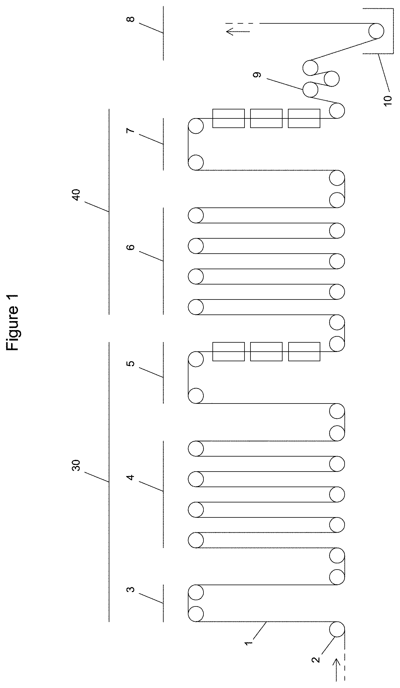
[0049] The diagram in FIG. 1 of the attached drawing provides a schematic representation of the processing sections of a continuous galvanizing line with two annealing furnaces 30, 40, in the state of the art. The sections of the line located up and downstream are not shown in this diagram. The strip 1, transported by rollers 2, first enters a preheating section 3, where it is for example direct-fire heated to 500.degree. C. for example. It then moves into the heating section 4, where annealing takes place at a temperature for example of 800.degree. C. The strip then passes into a cooling section 5 where it is cooled, for example down to 250.degree. C. It then enters a second heating section 6 where a second annealing takes place at a temperature for example of 700.degree. C. The strip then passes into a second cooling section 7 where it is cooled, for instance down to 460.degree. C. It then passes through a tensioning unit 9 before entering a coating section 8 where it is dipped in a zinc bath 10. The configuration of the line is simplified here to help in the description of the invention. A real line would include a wider diversity of sections, with for example chambers for heating, soaking, slow cooling, rapid cooling, overaging, and so on.
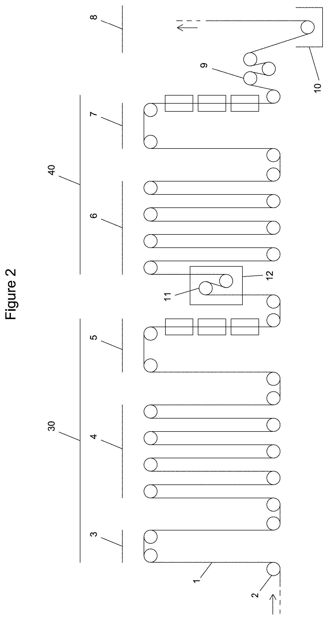
[0050] The diagram in FIG. 2 of the attached drawings provides a schematic representation of the processing sections of a continuous galvanizing line with two annealing furnaces as per a first assembly example of the invention. This figure again shows the process sections from FIG. 1, as already described. With the aim of separating or combining the management and control of tension in the two furnaces 30,40, a two-roller tensioning unit 11 is placed after the cooling section 5 of the first furnace and before the heating section 6 of the second furnace. The tensioning unit 11 is placed in a buffer volume 12 that manages atmosphere separation between the two furnaces.
[0051] The diagram in FIG. 3 of the attached drawings provides a schematic representation of the processing sections of a continuous galvanizing line with two annealing furnaces as per a second assembly example of the invention. This figure again shows the process sections already described. A strip accumulation section 14 between the two furnaces is located downstream, in terms of the strip running direction, of the cooling section 5 and upstream of the tensioning unit placed at the entry to the heating section 6 of the second furnace. As we have seen, this line configuration enables the accumulation of a certain length of strip in the accumulation section during stable operation phases, so that strip running speed in the first furnace can be reduced without change to strip running speed in the second furnace. It therefore enables the complete separation of the two consecutive furnaces in terms of strip running speed and tension management.
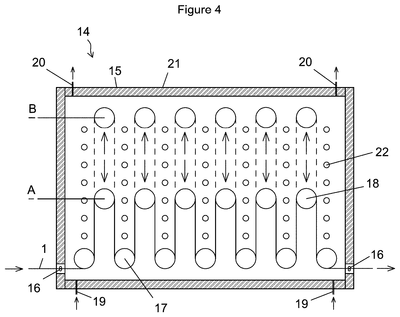
[0052] The diagram in FIG. 4 of the attached drawings provides a longitudinal schematic representation of a strip accumulation section 14 between the two annealing furnaces, as per one assembly example of the invention. This section includes a chamber 15 into which a strip 1 enters from the left of the figure and exits to the right, passing through atmosphere separation seals 16. The strip is transported by rollers 17, 18. The position of the set of seven rollers 17 in the bottom of the chamber 15 is fixed within the chamber. The six rollers 18, located above the set of rollers 17, move vertically between a lower position A and a higher position B so as to adjust the length of strip present in the chamber. The rollers 18 are mounted on a mobile frame linked to an elevating device, not shown in the diagram. The chamber 15 is kept under a protective atmosphere of a mixture of nitrogen and hydrogen, for example at 5% hydrogen. The atmosphere is, for example, injected into the chamber from injection points 19 and leaves the chamber through vents 20. The walls 21 of the chamber are gas-tight and thermally insulated with refractory materials, for example ceramic fiber, to limit the chamber's thermal losses. Heating device 22, for example electric radiant tubes, can bring the strip to or hold it at the desired temperature.
[0053] The diagram in FIG. 5 of the attached drawings provides a transverse schematic representation of the chamber 15 shown in FIG. 4. The rollers 17, with their position fixed in the chamber 15, are rotated by motors 23. The rollers 18, with their position adjustable in the chamber, are not motorized in this assembly example. They are rotated by the tension applied by the strip. The rollers 18 move vertically from a level A, in the lower part of the chamber, to a level B in the upper part of the chamber, through the action of a lifting device 24, comprising for instance two electric hoists (not shown) placed on each side of the chamber 15. Slots in the chamber walls allow the movement of the shafts of the rollers 18. These are equipped with means (not shown) to limit the flow of gas between the interior of the chamber and the volume housing the lifting device 24, for example brushes. The lifting device is kept under the same atmosphere as the chamber 15 with gas injection at injection points 25 and 26, in a volume created by gas-tight walls 27. The combination of gas-tight walls 21, 27 and atmosphere separation seals 16 help maintain the chamber under a protective atmosphere that is non-oxidant for the strip.
[0054] The production control and optimization system for a continuous annealing or galvanizing line for metal strips with two annealing furnaces, as per the invention, enables differentiated control of the strip running speed and level of tension in the two furnaces, by acting on the tensioning unit 11 and, when present, the accumulation section 14.
[0055] Of course, the invention is not limited to the examples described above and numerous adjustments can be made to these examples without moving outside the frame of the invention. Moreover, the invention's various characteristics, forms, variants and assembly methods can be linked to one another in different combinations to the extent that they remain compatible and do not exclude one another.
* * * * *
D00000
D00001
D00002
D00003
D00004
D00005
XML
uspto.report is an independent third-party trademark research tool that is not affiliated, endorsed, or sponsored by the United States Patent and Trademark Office (USPTO) or any other governmental organization. The information provided by uspto.report is based on publicly available data at the time of writing and is intended for informational purposes only.
While we strive to provide accurate and up-to-date information, we do not guarantee the accuracy, completeness, reliability, or suitability of the information displayed on this site. The use of this site is at your own risk. Any reliance you place on such information is therefore strictly at your own risk.
All official trademark data, including owner information, should be verified by visiting the official USPTO website at www.uspto.gov. This site is not intended to replace professional legal advice and should not be used as a substitute for consulting with a legal professional who is knowledgeable about trademark law.