Surface Cleaning Apparatus
Pougher; Simon ; et al.
U.S. patent application number 16/624652 was filed with the patent office on 2020-04-30 for surface cleaning apparatus. The applicant listed for this patent is TTI (MACAO COMMERCIAL OFFSHORE) LIMITED. Invention is credited to Jose Casella, Darren Holmes, Anna Jaanus, Simon Pougher, Richard Waters.
| Application Number | 20200129028 16/624652 |
| Document ID | / |
| Family ID | 59101510 |
| Filed Date | 2020-04-30 |


| United States Patent Application | 20200129028 |
| Kind Code | A1 |
| Pougher; Simon ; et al. | April 30, 2020 |
SURFACE CLEANING APPARATUS
Abstract
A surface cleaning apparatus including: a housing supporting: a suction source including a motor with an axle having an axis (A) which rotates a fan; a dirt collection chamber having an elongate axis (B); and a battery for providing power to operate the suction source, wherein the battery has an elongate axis (C); wherein the axis (A) of the motor axle and the elongate axis (B) of the dirt collection chamber extend transversely with respect to the elongate axis (C) of the battery.
| Inventors: | Pougher; Simon; (Birmingham West Midlands, GB) ; Holmes; Darren; (Birmingham West Midlands, GB) ; Waters; Richard; (Birmingham West Midlands, GB) ; Jaanus; Anna; (Birmingham West Midlands, GB) ; Casella; Jose; (Birmingham West Midlands, GB) | ||||||||||
| Applicant: |
|
||||||||||
|---|---|---|---|---|---|---|---|---|---|---|---|
| Family ID: | 59101510 | ||||||||||
| Appl. No.: | 16/624652 | ||||||||||
| Filed: | June 19, 2017 | ||||||||||
| PCT Filed: | June 19, 2017 | ||||||||||
| PCT NO: | PCT/GB2017/051786 | ||||||||||
| 371 Date: | December 19, 2019 |
| Current U.S. Class: | 1/1 |
| Current CPC Class: | A47L 5/24 20130101; A47L 9/322 20130101; A47L 9/2884 20130101; A47L 9/1608 20130101; A47L 9/16 20130101 |
| International Class: | A47L 9/28 20060101 A47L009/28; A47L 5/24 20060101 A47L005/24; A47L 9/16 20060101 A47L009/16; A47L 9/32 20060101 A47L009/32 |
Claims
1. A surface cleaning apparatus including: a housing supporting: a suction source including a motor with an axle having an axis (A) which rotates a fan; a dirt collection chamber having an elongate axis (B); and a battery for providing power to operate the suction source, wherein the battery has an elongate axis (C); wherein the axis (A) of the motor axle and the elongate axis (B) of the dirt collection chamber extend transversely with respect to the elongate axis (C) of the battery.
2. A surface cleaning apparatus including: a housing supporting: a suction source including a motor with an axle having an axis (A) which rotates a fan; a dirt collection chamber having an elongate axis (B); a cyclonic separator device having an elongate axis (B') for separating dirt from the airflow through the apparatus; and a battery for providing power to operate the suction source, wherein the battery has an elongate axis (C); wherein the axis (A) of the motor axle and the elongate axis (B') of the cyclonic separator device extend transversely with respect to the elongate axis (C) of the battery.
3. A surface cleaning apparatus including: a housing supporting: a suction source including a motor with an axle having an axis (A) which rotates a fan; a dirt collection chamber having an elongate axis (B); and a battery for providing power to operate the suction source; wherein the battery is positioned underneath the suction source and the dirt collection chamber.
4. A surface cleaning apparatus according to claim 3 including a cyclonic separating device having an elongate axis for separating dirt from the airflow through the apparatus.
5. A surface cleaning apparatus according to any preceding claim wherein the axis of the axle of the motor and the elongate axis of the dirt collection chamber cyclonic separator device are substantially parallel or are parallel.
6. A surface cleaning apparatus according to any preceding claim, wherein the elongate axis of the battery is parallel or substantially parallel to an elongate axis of the housing.
7. A surface cleaning apparatus according to claim 2, 4, 5 or 6 wherein the elongate axes of the dirt collection chamber and cyclonic separator device are parallel with each other, preferably co-axial or substantially co-axial.
8. A surface cleaning apparatus according to any preceding claim wherein the axis of the axle of the motor and the elongate axis of the dirt collection chamber/cyclonic separator device are spaced apart from the elongate axis of the battery, and optionally or preferably the axis of the axle of the motor is spaced apart from the battery a lesser amount than the elongate axis of the dirt collection chamber/cyclonic separator device.
9. A surface cleaning apparatus according to any preceding claim wherein the dirt collection chamber/cyclonic separator device and suction source are spaced apart along an elongate axis of the housing.
10. A surface cleaning apparatus according to any preceding claim wherein, in normal use, the axis of the axle of the motor is offset from the elongate axis of the dirt collection chamber/cyclonic separator device.
11. A surface cleaning apparatus according to claim 10, wherein the axis of the axle of the motor may lie in a first plane and the elongate axis of the dirt collection chamber/cyclonic separator device may lie in a second plane parallel to the first plane, wherein, in normal use, the second plane is below the first plane.
12. A surface cleaning apparatus according to any preceding claim wherein, in normal use, the elongate axis of the dirt collection chamber and/or cyclonic separator is substantially horizontal or is horizontal.
13. A surface cleaning apparatus according to any preceding claim wherein, in normal use, the battery is underneath at least a portion of or substantially all of the suction source.
14. A surface cleaning apparatus according to any preceding claim wherein, in normal use, the battery is underneath at least a portion of or substantially all of the dirt collection chamber and/or cyclonic separator device.
15. A surface cleaning apparatus according to any preceding claim wherein the housing includes a passage having an elongate axis (I) defining an inlet for receiving dirt-laden air.
16. A surface cleaning apparatus according to claim 15, wherein the axis (I) of the passage is transverse to the elongate axis (B) of the dirt collection chamber and/or cyclonic separator device and/or the axis (A) of the motor axle.
17. A surface cleaning apparatus according to claim 16, wherein the axis (I) intersects a portion of the suction source.
18. A surface cleaning apparatus according to claim 17, wherein, in normal use, the axis (I) intersects a lower portion of the suction source.
19. A surface cleaning apparatus according to any preceding claim wherein the battery includes a plurality of battery cells.
20. A surface cleaning apparatus according to claim 19 wherein, in normal use, a portion of the cells is positioned rearwardly of the suction source.
21. A surface cleaning apparatus according to claim 19 or 20 wherein a portion of the cells is arranged in a first row which extends along an elongate axis of the housing.
22. A surface cleaning apparatus according to claim 21 wherein a portion of the cells is arranged in a second row which extends above the first row and wherein the second row is shorter in length along an elongate axis of the battery than the first row.
23. A surface cleaning apparatus according to any preceding claim wherein the housing includes or is connected to a user graspable handle for holding the apparatus.
24. A surface cleaning apparatus according to claim 23, wherein, in normal use, the suction source and/or battery is positioned forwardly of a lower portion of the user graspable handle.
25. A surface cleaning apparatus according to any preceding claim wherein the apparatus is a handheld surface cleaning apparatus.
26. A surface cleaning apparatus according to any preceding claim including: a surface cleaning tool; an elongate member having an elongate axis (E), said elongate member connecting the surface cleaning tool to the housing and including a passage for carrying dirt-laden air from the surface cleaning tool to the dirt collection chamber.
27. A battery for use with a surface cleaning apparatus including: a housing having first and second ends and which includes: a first portion for receiving a first group of a plurality of battery cells; and a second portion for receiving a second group including at least one battery cell, wherein the second portion extends above the first portion and wherein there are fewer battery cells in the second group than in the first group.
28. A battery according to claim 27 wherein the first portion extends from the first to the second end of the housing and wherein the second portion only extends a portion of the distance along an elongate axis of the battery as measured from the second end towards the first end.
29. A battery according to claim 27 or 28 wherein the housing is L-shaped in cross-section.
30. A battery for use with a surface cleaning apparatus including: a housing having first and second ends and which includes: a first portion for receiving a first group of a plurality of battery cells; and a second portion for receiving a second group including at least one battery cell, wherein the first and second portions define a recess which extends part of the distance along an elongate axis of the battery as measured from the first end to the second end.
31. A battery according to claim 30 wherein the first portion defines a first wall of the recess and the second portion defines a second wall of the recess.
32. A battery according to claim 31 wherein the second wall extends transversely away from the first wall.
33. A battery according to claim 31 or 32 wherein the second wall is inclined with respect to the first wall.
34. A battery according to any one of claims 27 to 33 wherein the first and second portions contain the respective first and/or second groups of battery cells.
35. A battery according to any one of claims 27 to 34 wherein the first portion can house a maximum number of battery cells which is greater than the maximum number of battery cells that can be housed by the second portion.
36. A battery according to any one of claims 27 to 35 wherein the battery cells of the first and second groups are identical.
37. Any novel feature or novel combination of features described herein and/or in the accompanying drawings.
Description
DESCRIPTION OF INVENTION
[0001] This invention relates to a surface cleaning apparatus.
[0002] Different kinds of surface cleaning apparatus are known. Upright cleaners are known which have an upright part pivotally connected to a floor head and a user grasps a handle of the upright part to move the floor head back and forth over a floor surface to be cleaned. Cylinder cleaners are known for which the main operative components, i.e. suction source, dirt collection chamber, are supported by a housing having wheels. A rigid elongate member fluidly connects the operative components in the housing to a floor head and the user grasps a handle of the elongate member to move the floor head along the floor surface to be cleaned whilst the housing is moved by pulling the elongate member in the desired direction. Handheld cleaners are known which have a housing containing the operative components of the cleaner and for which the housing can be easily carried by the user during cleaning; such cleaners may or may not include a battery. Stick-vac or pole-vac cleaners are known which are formed by fluidly connecting a housing of a handheld unit to a floor head via a relatively rigid elongate member. For such cleaners, the user can steer the floor head by moving the handheld unit in the desired direction.
[0003] Surface cleaning apparatus having a compact configuration and/or ergonomic design are desirable.
[0004] According to an aspect of the present invention we provide a surface cleaning apparatus including: [0005] a housing supporting: [0006] a suction source including a motor with an axle having an axis (A) which rotates a fan; [0007] a dirt collection chamber having an elongate axis (B); and [0008] a battery for providing power to operate the suction source, wherein the battery has an elongate axis (C); [0009] wherein the axis (A) of the motor axle and the elongate axis (B) of the dirt collection chamber extend transversely with respect to the elongate axis (C) of the battery.
[0010] According to a further aspect of the present invention we provide a surface cleaning apparatus including: [0011] a housing supporting: [0012] a suction source including a motor with an axle having an axis (A) which rotates a fan; [0013] a dirt collection chamber having an elongate axis (B); [0014] a cyclonic separator device having an elongate axis (B') for separating dirt from the airflow through the apparatus; and [0015] a battery for providing power to operate the suction source, wherein the battery has an elongate axis (C); [0016] wherein the axis (A) of the motor axle and the elongate axis (B') of the cyclonic separator device extend transversely with respect to the elongate axis (C) of the battery.
[0017] According to a further aspect of the present invention we provide a surface cleaning apparatus including: [0018] a housing supporting: [0019] a suction source including a motor with an axle having an axis (A) which rotates a fan; [0020] a dirt collection chamber having an elongate axis (B); and [0021] a battery for providing power to operate the suction source; [0022] wherein the battery is positioned underneath the suction source and the dirt collection chamber.
[0023] The surface cleaning apparatus may include a cyclonic separating device having an elongate axis for separating dirt from the airflow through the apparatus.
[0024] The axis of the axle of the motor and the elongate axis of the dirt collection chamber cyclonic separator device may be substantially parallel or are parallel.
[0025] The elongate axis of the battery may be parallel or substantially parallel to an elongate axis of the housing.
[0026] The elongate axes of the dirt collection chamber and cyclonic separator device may be parallel with each other, preferably co-axial or substantially co-axial.
[0027] The axis of the axle of the motor and the elongate axis of the dirt collection chamber/cyclonic separator device may be spaced apart from the elongate axis of the battery, and optionally or preferably the axis of the axle of the motor is spaced apart from the battery a lesser amount than the elongate axis of the dirt collection chamber/cyclonic separator device.
[0028] The dirt collection chamber/cyclonic separator device and suction source may be spaced apart along an elongate axis of the housing.
[0029] In normal use, the axis of the axle of the motor may be offset from the elongate axis of the dirt collection chamber/cyclonic separator device.
[0030] The axis of the axle of the motor may lie in a first plane and the elongate axis of the dirt collection chamber/cyclonic separator device may lie in a second plane parallel to the first plane, wherein, in normal use, the second plane is below the first plane.
[0031] In normal use, the elongate axis of the dirt collection chamber and/or cyclonic separator may be substantially horizontal or horizontal.
[0032] In normal use, the battery may be underneath at least a portion of or substantially all of the suction source.
[0033] In normal use, the battery may be underneath at least a portion of or substantially all of the dirt collection chamber and/or cyclonic separator device.
[0034] The housing may include a passage having an elongate axis (I) defining an inlet for receiving dirt-laden air.
[0035] The axis (I) of the passage may be transverse to the elongate axis (B) of the dirt collection chamber and/or cyclonic separator device and/or the axis (A) of the motor axle.
[0036] The axis (I) may intersect a portion of the suction source.
[0037] In normal use, the axis (I) may intersect a lower portion of the suction source.
[0038] The battery may include a plurality of battery cells.
[0039] In normal use, a portion of the cells may be positioned rearwardly of the suction source.
[0040] A portion of the cells may be arranged in a first row which extends along an elongate axis of the housing.
[0041] A portion of the cells may be arranged in a second row which extends above the first row and wherein the second row may be shorter in length along an elongate axis of the battery than the first row.
[0042] The housing may include or may be connected to a user graspable handle for holding the apparatus.
[0043] In normal use, the suction source and/or battery may be positioned forwardly of a lower portion of the user graspable handle.
[0044] The apparatus may be a handheld surface cleaning apparatus.
[0045] The surface cleaning apparatus may include: [0046] a surface cleaning tool; [0047] an elongate member having an elongate axis (E), said elongate member connecting the surface cleaning tool to the housing and including a passage for carrying dirt-laden air from the surface cleaning tool to the dirt collection chamber.
[0048] According to a further aspect of the invention we provide a battery for use with a surface cleaning apparatus including: [0049] a housing having first and second ends and which includes: [0050] a first portion for receiving a first group of a plurality of battery cells; and [0051] a second portion for receiving a second group including at least one battery cell, [0052] wherein the second portion extends above the first portion and wherein there are fewer battery cells in the second group than in the first group.
[0053] The first portion may extend from the first to the second end of the housing and the second portion may only extend a portion of the distance along an elongate axis of the battery as measured from the second end towards the first end.
[0054] The housing may be L-shaped in cross-section.
[0055] According to a further aspect of the invention we provide a battery for use with a surface cleaning apparatus including:
[0056] a housing having first and second ends and which includes: [0057] a first portion for receiving a first group of a plurality of battery cells; and [0058] a second portion for receiving a second group including at least one battery cell, [0059] wherein the first and second portions define a recess which extends part of the distance along an elongate axis of the battery as measured from the first end to the second end.
[0060] The first portion may define a first wall of the recess and the second portion may define a second wall of the recess.
[0061] The second wall may extend transversely away from the first wall.
[0062] The second wall may be inclined with respect to the first wall.
[0063] The first and second portions may contain the respective first and/or second groups of battery cells.
[0064] The first portion may be able to house a maximum number of battery cells which is greater than the maximum number of battery cells that can be housed by the second portion.
[0065] The battery cells of the first and second groups may be identical.
[0066] According to a further aspect of the invention we provide a surface cleaning apparatus according to any preceding aspect including a battery according to any corresponding preceding aspect.
[0067] Embodiments of the invention will be set out below by way of example only with reference to the accompanying figures, of which:
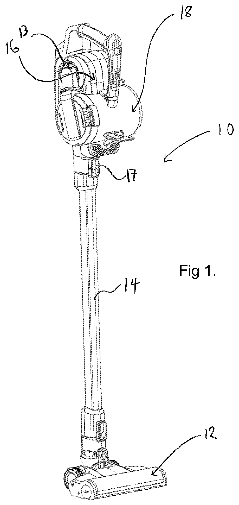
[0068] FIG. 1 is a perspective view of a surface cleaning apparatus;
[0069] FIG. 2 is a front view of the apparatus of FIG. 1;
[0070] FIG. 3 is a side view of the apparatus FIG. 1;
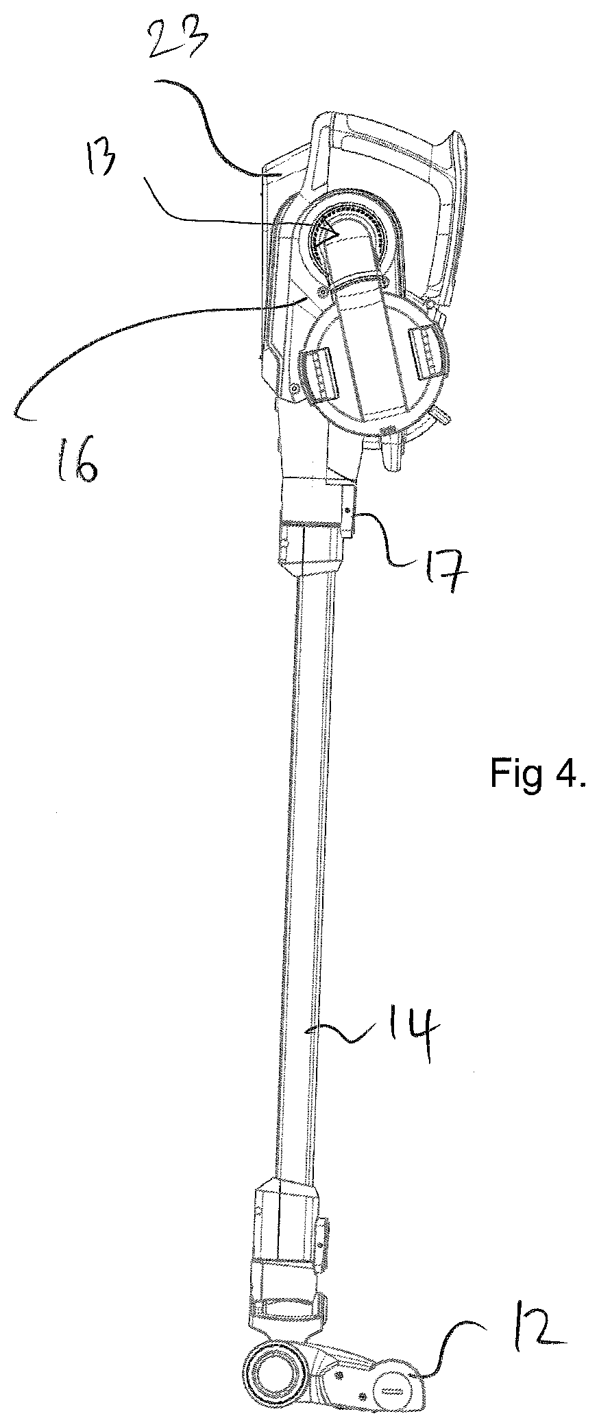
[0071] FIG. 4 is an opposite side view of the apparatus FIG. 1;
[0072] FIG. 5 is a perspective view of a housing of the apparatus of FIG. 1, which housing is operable as a handheld surface cleaning apparatus;
[0073] FIG. 6 is a side view of the housing of FIG. 5;
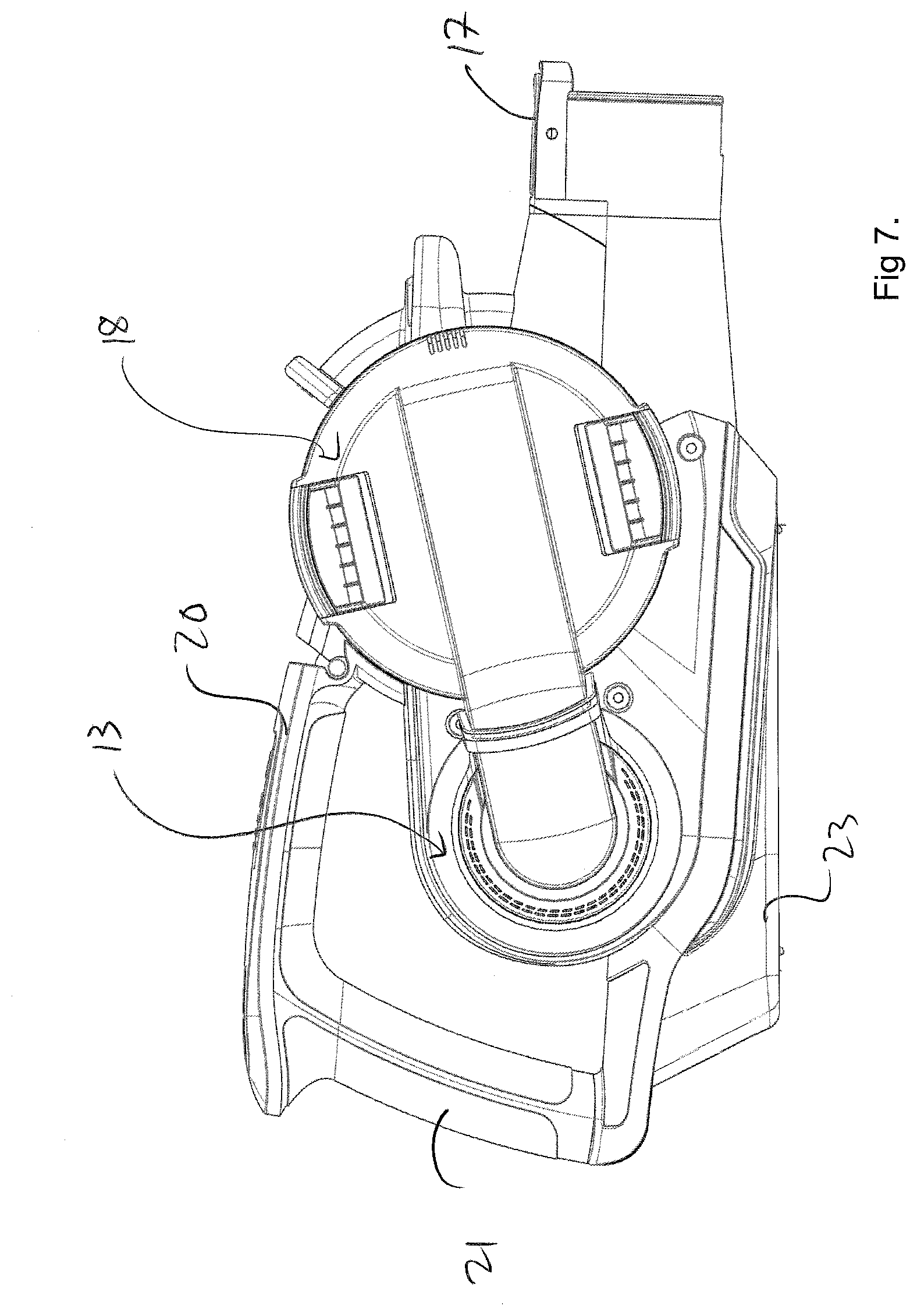
[0074] FIG. 7 is an opposite side view of the housing of FIG. 5;
[0075] FIG. 8 is a cross-sectional view of the housing from the same side as shown in FIG. 7;
[0076] FIG. 9 is a cross-sectional view of the housing from the same side as shown in FIG. 6; and
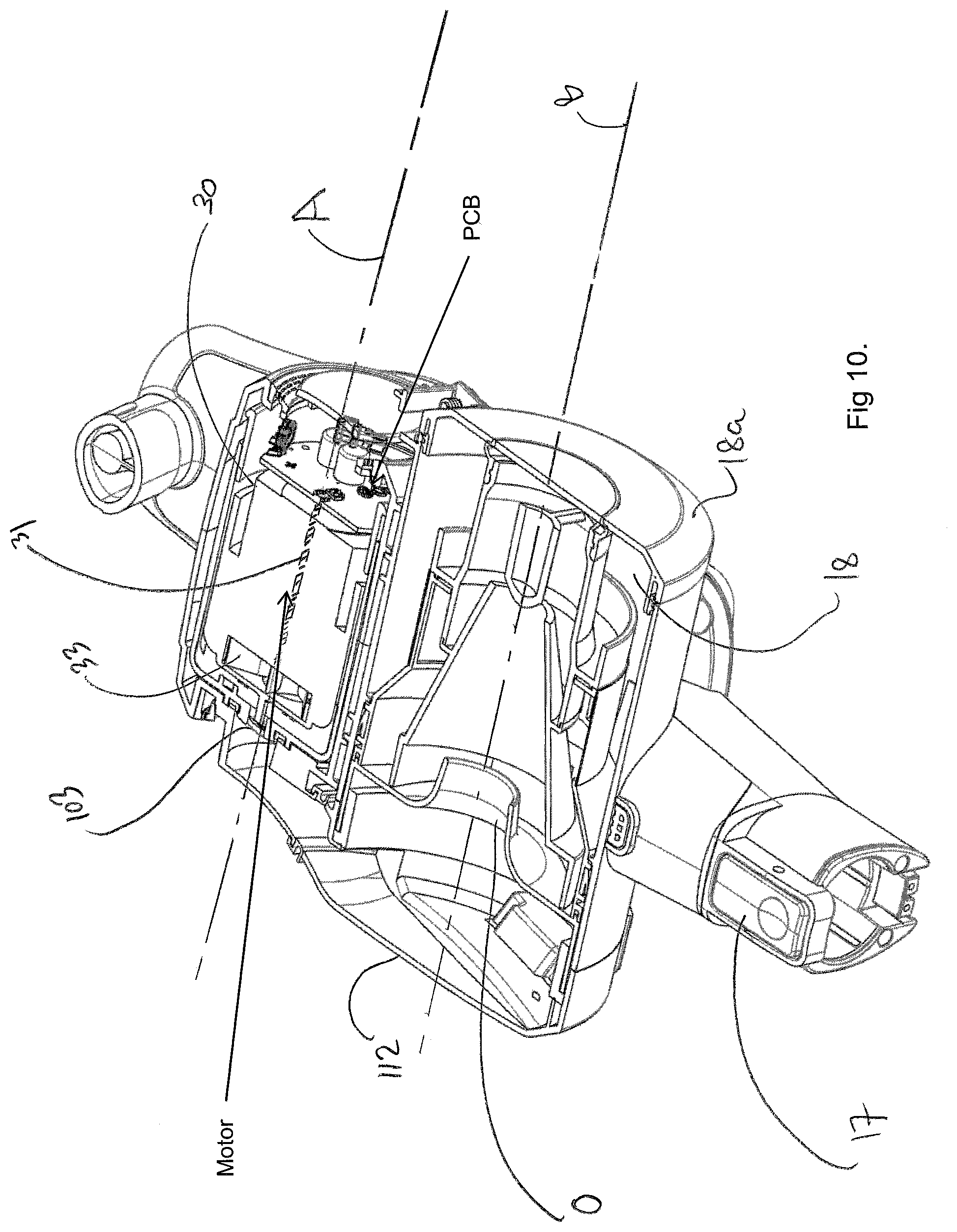
[0077] FIG. 10 is a cross-sectional perspective view of the housing of FIG. 5.
[0078] Referring to the figures, these show a surface cleaning apparatus 10 in accordance with the present invention. The apparatus 10 includes a surface cleaning tool 12 (a floor head in this example), a housing 16 having an elongate axis H and an elongate member 14, having an elongate axis E, connecting the surface cleaning tool 12 to the housing 16. The elongate member 14 is relatively rigid. The housing 16, in this example, is operable as a handheld surface cleaning apparatus, commonly known as a hand vac, when the elongate member 14 is not connected thereto, and in this state the housing 16 can be used with or without the surface cleaning tool 12 connected thereto. The housing 16 supports a suction source 13, a dirt collection chamber 18 and a cyclonic separator. The suction source 13 and dirt collection chamber 18 are spaced apart along axis H of the housing 16. In this example the suction source 13 is an electric motor driving a rotatable fan, but any appropriate suction source may be used. All that is necessary is for the suction source to be able to draw air through the surface cleaning tool 12 and elongate member 14 towards the dirt collection chamber 18. Dirt collection chamber 18 has an elongate axis B.
[0079] FIG. 8 shows the elongate axis H at a particular height but it will be appreciated that the axis H could be a different height and that axis H should be understood to denote an axis which is parallel to the horizontal or lengthwise direction in which the housing 16 extends between its distal ends, as viewed in side cross-section (such as that shown in FIG. 8). In other words, parallel to the generally elongate dimension of the housing 16.
[0080] In this example the housing 16 supports or contains a battery 23 to provide electrical power to the suction motor and other components of the apparatus 10. Battery 23 is of a generally elongate shape and has an elongate axis C. Axis C is parallel to the axis H of the housing 16. FIG. 8 shows the elongate axis C at a particular height but it will be appreciated that the axis C could be a different height and that axis C should be understood to denote an axis which is parallel to the horizontal or lengthwise direction in which the battery 23 extends between its distal ends, as viewed in side cross-section (such as that shown in FIG. 8). In other words, parallel to the generally elongate dimension of the battery. In alternative embodiments, the apparatus 10 may be mains powered.
[0081] In this example, the housing 16 includes a passage 19 in fluid communication with an inlet of the cyclonic separator. Passage 19 has an elongate axis I and defines an inlet for receiving dirt-laden air and the inlet is connectable to the elongate member 14. When connected, axis I is parallel to the elongate axis E of the elongate member. In embodiments, axis I may be co-axial or offset from the elongate axis E.
[0082] Whilst in the present embodiment the apparatus 10 includes a cyclonic separator to separate dirt from the air flowing through the apparatus 10, this is not essential. Indeed, embodiments are envisaged where the apparatus 10 includes a filter bag which collects dirt, or any other appropriate device to separate the dirt from the air. The apparatus 10 includes a pivotally moveable door 18a which enables a user to empty dirt collected within the chamber 18.
[0083] The elongate member 14 includes a passage for carrying dirt-laden air from the surface cleaning tool 12 to the dirt collection chamber 18. In this example the surface cleaning tool 12 includes a motor for driving a rotatable floor agitating member or brush, so the elongate member 14 includes a further passage through which electrical cables may extend to provide an electric connection between the housing 16 and the motor in the surface cleaning tool 12.
[0084] The surface cleaning tool 12 is disconnectable from the elongate member 14, so that, for example, another tool can be connected to the free end of the elongate member 14. The elongate member 14 is also disconnectable from the housing 16, by way of a manually operated switch 17. This enables the housing 16 to be used as handheld surface cleaning apparatus, with the option of being able to connect another tool to the location from where the elongate member 16 is removed.
[0085] The housing 16 includes a handle for holding the apparatus 10, said handle including first 20 and second 21 user-graspable portions which are connected to each other substantially at right-angles. A first end of the first user-graspable portion 20 is connected to the housing 16 and extends generally rearwardly away therefrom and from the elongate member 14. A first end of the second user-graspable portion 21 is connected to the housing 16 and extends generally upwardly therefrom. Respective second ends of the first 20 and second 21 user-graspable portions are connected to each other. Essentially, the first 20 and second 21 user-graspable portions form a handle which is L-shaped and which provides two locations each of which is sized such that it can be grasped fully by a hand of a user. A device 22, e.g. a switch, for turning the apparatus "on" is positioned at the connection of the second ends of the first 20 and second 21 user-graspable portions to each other.
[0086] As can be seen from FIGS. 8 and 9, the housing 16 supports the suction source 13 which is in the form of an electric motor 30 with an axle 31 which is connected at one end to a fan 33. The axle 31 and fan 33 rotate about an axis A. The motor 30 may be any appropriate motor, e.g. DC, AC, brushless.
[0087] The motor 30, axle 31 and fan 33 are positioned such that axis A extends transversely to the elongate axis H of the housing 16. The axis A of the axle 31 and axis B of the dirt collection chamber 18 extend perpendicularly to the axis C of the battery 23. In more detail, it will be appreciated from FIG. 2 that the axis E of the elongate member 14 is substantially perpendicular to the axis A of the axle 31 of the motor 30 when viewed in plan view. It will also be appreciated that the axis C of the battery 23 is below (i.e. underneath) the axis E and below (i.e. underneath) the axis A of the axle 31 when viewed from the side (see FIG. 8). In other words, axes C, E and A lie in respective planes which are parallel to one another and the plane in which C lies is below the other planes in which axes E and A lie.
[0088] The cyclonic separator device has an elongate axis B' coaxial with the axis B of the dirt collection chamber 18, the axis B being that about which dirt-laden air is caused to rotate as it passes through the apparatus 10. The elongate axis B is substantially horizontal in normal use. The axis B is parallel to the axis A of the axle 31 of the motor 30. It will also be appreciated that the axis B and axis A are offset from each other, with axis B being above axis A. With reference to FIG. 2, it can be seen that, when viewed from the side, axis E of the elongate member 14 is substantially perpendicular to the axis B of the dirt collection chamber 18. It can also be seen from FIG. 3 that axis E is below the axis B and axis A when viewed from the side.
[0089] An upstream wall 112 of the housing 16 extends along the elongate axis H of the housing 16 and has an inner surface which partially defines an air flow passage from an inlet 103 of the suction source 13 to an outlet 0 of the cyclonic separator upstream of the suction source 13.
[0090] Normal use of the surface cleaning apparatus 10 refers to use thereof when the elongate axis E is inclined an acute angle with respect to the surface being cleaned. In other embodiments for which the surface cleaning apparatus 10 is a cylinder cleaner, the housing may be generally upright with respect to the floor surface during normal use, and the axes B and C parallel with the floor surface. For embodiments where the apparatus 10 is an upright cleaner, the housing may be inclined with respect to the floor surface and the axes B and C may be parallel with the floor surface during normal use.
[0091] In normal use, the axis A of the axle of the motor 30 may lie in a first plane and the elongate axes of the dirt collection chamber/cyclonic separator device B, may lie in a second plane which is parallel to the first plane; wherein the second plane is below the first plane.
[0092] It can also be seen that axis I is transverse to the elongate axis B and axis A. In normal use, the axis I intersects a lower part of the suction source 13.
[0093] Whilst in this embodiment the elongate axes of the dirt collection chamber 18 and the cyclonic separator device are coaxial or substantially coaxial, they need not be. They could, for example, be parallel and offset from each other.
[0094] In normal use, the motor 30 is positioned rearwardly of the dirt collection chamber 18. It will also be appreciated that the battery 23 is positioned below or underneath the motor 30 and the dirt collection chamber/cyclonic separator device. In particular, the elongate axis C is below or underneath the respective axes A and B of the axle 31 and dirt collection chamber 18. This positioning assists in advantageously distributing the weight of the components in the housing 16 whilst minimising the overall height of the apparatus 10.
[0095] The arrangement of the suction source, dirt collection chamber and battery described has improved ergonomic characteristics as well as a reduced compact height.
[0096] In more detail, battery 23 has a housing having first and second ends 50, 52 which are spaced apart along elongate axis C. The housing has first and second portions 54, 56. The first portion 54 is generally rectangular in shape and the second portion 56 extends upwardly away from an end of the first portion 54. The second portion 56 extends above a part of the first portion 54 in a direction elongate axis C. The first and second portions 54, 56 define a recess 58 which extends part of the distance from the first end to the second end of the battery 23. In more detail, the first portion 54 defines a first wall 60 of the recess 58 and the second portion 56 defines a second wall 62 of the recess 58. The second wall 62 is inclined with respect to the first wall 60. Thus, the battery 23 is generally L-shaped from the side (see FIG. 9). The first and second walls 60, 62 that define the recess 58 abut a corresponding formation (not shown) of the housing 16 when the battery 23 is docked. In other words, the length of the second portion 56 is shorter than the length of the first portion 54 as measured from the first end 50 to the second end 52.
[0097] The first portion 54 houses a first group of a plurality of battery cells in a first row and the second portion 56 houses a second group of a fewer number of battery cells in a second row. The second portion 56 extends away from and is positioned rearwardly of the suction source with respect to axis H of the housing 16.
[0098] The configuration of the battery is advantageous because the capacity of the battery (which corresponds to the working time of the apparatus) can be changed by simply adding or not adding battery cells to the second portion of the housing during manufacture. In the prior art, the limitations of the battery housing design often mean that for the same housing one must use a different type of battery cell if different battery capacities are required. In contrast, for the present invention, one can use identical battery cells with the same battery housing and the capacity of the battery can be changed by adding more or fewer (identical) batteries depending on the application.
[0099] It will be appreciated that any appropriate motor could be used in the apparatus 10, and any appropriate handle configuration could be used.
[0100] When used in this specification and claims, the terms "comprises" and "comprising" and variations thereof mean that the specified features, steps or integers are included. The terms are not to be interpreted to exclude the presence of other features, steps or components.
[0101] The features disclosed in the foregoing description, or the following claims, or the accompanying drawings, expressed in their specific forms or in terms of a means for performing the disclosed function, or a method or process for attaining the disclosed result, as appropriate, may, separately, or in any combination of such features, be utilised for realising the invention in diverse forms thereof.
* * * * *
D00000
D00001
D00002
D00003
D00004
D00005
D00006
D00007
D00008
D00009
D00010
XML
uspto.report is an independent third-party trademark research tool that is not affiliated, endorsed, or sponsored by the United States Patent and Trademark Office (USPTO) or any other governmental organization. The information provided by uspto.report is based on publicly available data at the time of writing and is intended for informational purposes only.
While we strive to provide accurate and up-to-date information, we do not guarantee the accuracy, completeness, reliability, or suitability of the information displayed on this site. The use of this site is at your own risk. Any reliance you place on such information is therefore strictly at your own risk.
All official trademark data, including owner information, should be verified by visiting the official USPTO website at www.uspto.gov. This site is not intended to replace professional legal advice and should not be used as a substitute for consulting with a legal professional who is knowledgeable about trademark law.