Vacuum Cleaner Combination And Stick Vacuum Cleaner
Zhong; Hongfeng ; et al.
U.S. patent application number 16/728556 was filed with the patent office on 2020-04-30 for vacuum cleaner combination and stick vacuum cleaner. The applicant listed for this patent is Positec Power Tools (Suzhou) Co., Ltd.. Invention is credited to Goujun Chen, Xianghua Meng, Xiaoli Pang, Hongbing Wu, Binbin Xu, Jingtao Xu, Jinping Zhang, Shisong Zhang, Hongfeng Zhong.
| Application Number | 20200129024 16/728556 |
| Document ID | / |
| Family ID | 64802202 |
| Filed Date | 2020-04-30 |


View All Diagrams
| United States Patent Application | 20200129024 |
| Kind Code | A1 |
| Zhong; Hongfeng ; et al. | April 30, 2020 |
VACUUM CLEANER COMBINATION AND STICK VACUUM CLEANER
Abstract
A vacuum cleaner combination includes a dust suction apparatus and a dust bin configured to be coupled to the cup body and collect dust sucked by the dust suction apparatus. The vacuum cleaner combination is operable in and a second working mode. In the first working mode, the dust suction apparatus is not coupled to the dust bin, and the dust suction apparatus independently works and is responsible for dust suction and dust collection. In the second working mode, the dust suction apparatus is coupled to the dust bin, and the dust suction apparatus and the dust bin are both responsible for dust collection. Compared with the prior art, in the present invention, a dust bin detachable from a dust suction apparatus is disposed, so that a dust collection chamber of a vacuum cleaner is flexibly increased dust
| Inventors: | Zhong; Hongfeng; (Suzhou, CN) ; Xu; Jingtao; (Suzhou, CN) ; Zhang; Shisong; (Suzhou, CN) ; Xu; Binbin; (Suzhou, CN) ; Pang; Xiaoli; (Suzhou, CN) ; Wu; Hongbing; (Suzhou, CN) ; Chen; Goujun; (Suzhou, CN) ; Meng; Xianghua; (Suzhou, CN) ; Zhang; Jinping; (Suzhou, CN) | ||||||||||
| Applicant: |
|
||||||||||
|---|---|---|---|---|---|---|---|---|---|---|---|
| Family ID: | 64802202 | ||||||||||
| Appl. No.: | 16/728556 | ||||||||||
| Filed: | December 27, 2019 |
Related U.S. Patent Documents
| Application Number | Filing Date | Patent Number | ||
|---|---|---|---|---|
| PCT/CN2018/093481 | Jun 28, 2018 | |||
| 16728556 | ||||
| Current U.S. Class: | 1/1 |
| Current CPC Class: | A47L 9/106 20130101; A47L 5/28 20130101; A47L 9/19 20130101; A47L 9/00 20130101; A47L 5/00 20130101; A47L 5/225 20130101; A47L 9/1683 20130101; A47L 9/2842 20130101; A47L 9/165 20130101; A47L 9/122 20130101; A47L 9/242 20130101; A47L 9/1608 20130101; A47L 9/1666 20130101; A47L 5/24 20130101; A47L 9/02 20130101; A47L 9/2894 20130101; A47L 5/362 20130101; A47L 9/1658 20130101; A47L 9/127 20130101; A47L 9/322 20130101; A47L 9/1691 20130101; A47L 9/1409 20130101; A47L 9/2805 20130101 |
| International Class: | A47L 9/16 20060101 A47L009/16; A47L 9/10 20060101 A47L009/10 |
Foreign Application Data
| Date | Code | Application Number |
|---|---|---|
| Jun 28, 2017 | CN | 201710508580.9 |
| Feb 28, 2018 | CN | 201810168406.9 |
| Jun 22, 2018 | CN | 2018106511780 |
| Jun 26, 2018 | CN | 2018106690901 |
| Jun 26, 2018 | CN | 2018106707207 |
| Jun 26, 2018 | CN | 2018106721882 |
Claims
1. A vacuum cleaner combination, comprising: a dust suction apparatus, comprising a housing, a dust suction inlet, and a dust cup assembly connected to the housing, wherein the dust cup assembly comprises a cup body; and a dust bin, configured to be coupled to the cup body and collect dust sucked by the dust suction apparatus, wherein the dust bin and the cup body are in communication with each other, wherein the vacuum cleaner combination is operable in and a second working mode; in the first working mode, the dust suction apparatus is not coupled to the dust bin, and the dust suction apparatus independently works and is responsible for dust suction and dust collection; and in the second working mode, the dust suction apparatus is coupled to the dust bin, and the dust bin and the cup body are both responsible for dust collection.
2. The vacuum cleaner combination according to claim 1, wherein the dust bin comprises a dust chamber and a dust inlet in communication with the dust chamber, and the dust inlet receives dust passing through the dust suction apparatus when the vacuum cleaner combination is in the second working mode.
3. The vacuum cleaner combination according to claim 2, wherein the cup body is provided with a dust outlet, and the dust outlet is airtightly joined to the dust inlet in the second working mode.
4. The vacuum cleaner combination according to claim 3, wherein a first sealing member is disposed between the dust outlet and the dust inlet.
5. The vacuum cleaner combination according to claim 4, wherein the dust outlet is columnar, the size of the dust inlet is greater than that of the dust outlet, and the first sealing member is disposed between the dust outlet and the dust inlet.
6. The vacuum cleaner combination according to claim 4, wherein the dust cup is provided with a dust cup cover configured to seal the dust outlet, and a second sealing member implementing the seal between the dust outlet and the dust cup cover, and the first sealing member circumferentially surrounds the second sealing member and the dust cup cover.
7. The vacuum cleaner combination according to claim 6, wherein the dust bin is provided with an abutting portion configured to control the dust cup cover to automatically open, and the abutting portion is disposed at the dust inlet and is located inside the first sealing member.
8. The vacuum cleaner combination according to claim 6, wherein the handheld vacuum cleaner is provided with a latching portion controlling the dust cup cover to open or close, the abutting portion is provided with a first location, and the abutting portion is capable of abutting and fitting the latching portion at the first location to control the dust cup cover to open.
9. The vacuum cleaner combination according to claim 8, wherein the handheld vacuum cleaner is also provided with a rotating portion and a reset structure, when the latching portion controls the dust cup cover to open, the dust cup cover rotates around the rotating portion, and when the latching portion releases locking, the dust cup cover is driven by the reset structure to open outward.
10. The vacuum cleaner combination according to claim 9, wherein the dust cup cover automatically opens outward by an angle in a range of 110.degree. to 190.degree..
11. The vacuum cleaner combination according to claim 2, wherein the dust bin comprises a base portion and a top portion that fits the base portion, and the top portion is provided with the dust inlet.
12. The vacuum cleaner combination according to claim 11, wherein the base portion is provided with a bottom surface located at the bottom and a side surface that is connected to the bottom surface and forms the dust chamber together with the bottom surface, and the side surface is provided with a transparent window.
13. The vacuum cleaner combination according to claim 11, wherein the base portion and the top portion flexibly fit each other.
14. The vacuum cleaner combination according to claim 1, wherein a first fixing structure and a second fixing structure are respectively disposed at two ends of the dust bin, and the handheld vacuum cleaner is provided with a first positioning buckle buckled with the first fixing structure and a second positioning buckle buckled with the second fixing structure.
15. The vacuum cleaner combination according to claim 1, wherein the dust suction apparatus comprises the dust cup assembly and a motor assembly, the dust cup assembly comprises the cup body and a cyclone separator disposed inside the cup body, the motor assembly is configured to generate a negative suction pressure, and the motor assembly is located between the dust suction inlet and the dust cup assembly.
16. The vacuum cleaner combination according to claim 15, wherein the dust suction inlet has an air inlet axis, the motor assembly has a motor axis, and the air inlet axis and the motor axis are parallel to each other.
17. The vacuum cleaner combination according to claim 15, wherein the dust suction apparatus comprises a flow-directing structure, and the flow-directing structure is connected to the dust suction inlet and the cup body to guide a dusty airflow into the cup body through the dust suction inlet.
18. The vacuum cleaner combination according to claim 17, wherein the flow-directing structure is bent and extends outward in a pipe shape from an end, near the dust suction inlet, of the housing, and is connected to a side of the cup body and is in communication with the cup body.
19. The vacuum cleaner combination according to claim 15, wherein the dust suction apparatus is provided with a battery assembly, and the battery assembly and the motor assembly are respectively located on two sides of the cup body.
20. The vacuum cleaner combination according to claim 19, wherein the cup body is provided with a dust outlet located at the bottom of the vacuum cleaner combination, and the battery assembly is located at an end, near the dust outlet, of the cup body.
21. The vacuum cleaner combination according to claim 15, wherein the dust suction apparatus comprises a handle assembly, the handle assembly is used for gripping, the handle assembly comprises a first gripping area and a second gripping area, and gripping directions of the first gripping area and the second gripping area are different.
22. The vacuum cleaner combination according to claim 21, wherein the first gripping area is near the motor assembly and is located above the cup body.
23. The vacuum cleaner combination according to claim 21, wherein the second gripping area extends in a length direction of the cup body, and the second gripping area and the motor assembly are respectively located on two sides of the cup body.
24. The handheld vacuum cleaner according to claim 23, wherein the dust suction apparatus is provided with a battery assembly, and the battery assembly is located below the second gripping area and is mounted adjacent to the second gripping area.
25. The handheld vacuum cleaner according to claim 21, wherein an angle between the first gripping area and the second gripping area is from 90.degree. to 135.degree..
26. The vacuum cleaner combination according to claim 1, wherein the dust suction apparatus comprises the dust cup assembly and a motor assembly, the dust cup assembly comprises a cyclone separator disposed inside the cup body and provided with a plurality of airflow through holes and a filter disposed inside the cyclone separator, and the cyclone separator circumferentially surrounds at least a part of the filter.
27. The vacuum cleaner combination according to claim 26, wherein the cyclone separator comprises a main body, the main body is a hollow cone whose outer diameter decreases towards the bottom of the cup body, and the plurality of airflow through holes are opened in the main body.
28. The vacuum cleaner combination according to claim 26, wherein the filter is a hollow cone whose outer diameter decreases towards the bottom of the cup body, and the filter forms an airflow outlet channel in communication with the motor assembly in an axial direction.
29. The vacuum cleaner combination according to claim 26, wherein the material of the filter is waterproof hypalon.
30. The vacuum cleaner combination according to claim 26, wherein the filter is columnar, and is surrounded by laminated waterproof hypalon to form a hollow columnar shape, and a fold height of the filter is from 2 mm to 20 mm; and/or, a lateral area of the column of the filter is from 15,000 square millimeters to 20,000 square millimeters; and/or, an unfolded area of the filter is from 80,000 square millimeters to 120,000 square millimeters.
31. The vacuum cleaner combination according to claim 1, wherein the dust cup assembly comprises a cyclone separator disposed inside the cup body and provided with a plurality of airflow through holes and a filter disposed inside the cyclone separator, a motor assembly is configured to supply power and generate a negative suction pressure, and in the first working mode, a dusty airflow enters the cyclone separator through the airflow through holes after entering the cup body and rotating around the cyclone separator, and flows upward to flow to the motor assembly for discharge after being filtered by the filter inside the cyclone separator.
32. The vacuum cleaner combination according to claim 1, wherein the dust cup assembly comprises a cyclone separator disposed inside the cup body and provided with a plurality of airflow through holes and a filter disposed inside the cyclone separator, and a motor assembly is configured to supply power and generate a negative suction pressure, and in the second working mode, after a dusty airflow enters the cup body and rotates around the cyclone separator and is separated, a part of the airflow flows upward to flow to the motor assembly for discharge after being filtered by the filter inside the cyclone separator; and the other part of the airflow flows upward to the cup body after flowing to an expansion box of the dust bin, and flows upward to the motor assembly for discharge after being filtered by the filter inside the cyclone separator.
33. The vacuum cleaner combination according to claim 32, wherein the cyclone separator comprises a flow-guiding structure, and the flow-guiding structure is disposed below a main body and comprises a plurality of guiding bars; and the guiding bars are arranged diagonally and an arrangement direction is the same as an airflow rotating direction.
34. A vacuum cleaner combination, comprising: a dust suction apparatus, comprising a housing, a dust suction inlet, and a dust cup assembly connected to the housing, wherein the dust cup assembly comprises a cup body; and a dust bin, configured to be coupled to the cup body and collect dust sucked by the dust suction apparatus, wherein the dust bin and the cup body are in communication with each other, wherein the vacuum cleaner combination is operable in and a second working mode, the dust suction apparatus has a first dust collection capacity, and the dust bin has a second dust collection capacity; in the first working mode, a dust collection capacity is the first dust collection capacity; and in the first working mode, the dust collection capacity is the sum of the first dust collection capacity and the second dust collection capacity.
35. A stick vacuum cleaner, comprising a hollow extension pipe and a cleaner head, wherein the stick vacuum cleaner further comprises the vacuum cleaner combination according to any one of claims 1 to 33, a dust suction apparatus in the vacuum cleaner combination is detachably connected to an extension pipe, one end of the extension pipe is in communication with a dust suction inlet of the dust suction apparatus, the other end of the extension pipe is in communication with the cleaner head, and the cleaner head is provided with a suction channel in communication with the inside of the extension pipe.
Description
BACKGROUND
Technical Field
[0001] The present invention relates to the field of cleaning technologies, and in particular, to a vacuum cleaner combination provided with a dust bin, and a stick vacuum cleaner provided with the vacuum cleaner combination.
Related Art
[0002] In the prior art, there are usually lots of dust such as sawdust and sewage with dust in an environment such as a garage. A common vacuum cleaner has only a dust collection space of a dust bag or dust cup. The space is soon filled with dust when there is plenty, and needs to be repeatedly emptied. In addition, as more dust is collected, the efficiency of separation is reduced.
[0003] Therefore, for the problems in the prior art, it is necessary to provide a flexibly disposed dust bin capable of increasing a dust collection space, a vacuum cleaner combination provided with the dust bin, and a stick vacuum cleaner provided with the vacuum cleaner combination.
SUMMARY
[0004] The present invention provides a flexibly disposed dust bin capable of increasing a dust collection space, a vacuum cleaner combination provided with the dust bin, and a stick vacuum cleaner provided with the vacuum cleaner combination. Based on the design of the dust bin, the vacuum cleaner combination can meet cleaning requirements of different scenarios, thereby improving the application range.
[0005] To achieve the foregoing objective, a technical solution of the present invention is:
[0006] A vacuum cleaner combination, comprising:
[0007] a dust suction apparatus, comprising a housing, a dust suction inlet, and a dust cup assembly connected to the housing, wherein the dust cup assembly comprises a cup body; and
[0008] a dust bin, configured to be coupled to the cup body and collect dust sucked by the dust suction apparatus, wherein the dust bin and the cup body are in communication with each other, wherein
[0009] the vacuum cleaner combination is operable in and a second working mode;
[0010] in the first working mode, the dust suction apparatus is not coupled to the dust bin, and the dust suction apparatus independently works and is responsible for dust suction and dust collection; and
[0011] in the second working mode, the dust suction apparatus is coupled to the dust bin, the dust suction apparatus is responsible for dust suction, and the dust bin is responsible for dust collection.
[0012] Preferably, the dust bin comprises a dust chamber and a dust inlet in communication with the dust chamber, and the dust inlet receives dust passing through the dust suction apparatus when the vacuum cleaner combination is in the second working mode.
[0013] Preferably, the cup body is provided with a dust outlet, and the dust outlet is airtightly joined to the dust inlet in the second working mode.
[0014] Preferably, a first sealing member is disposed between the dust outlet and the dust inlet.
[0015] Preferably, the dust outlet is columnar, the size of the dust inlet is greater than that of the dust outlet, and the first sealing member is disposed between the dust outlet and the dust inlet.
[0016] Preferably, the dust cup assembly is provided with a dust cup cover configured to seal the dust outlet, and a second sealing member implementing the seal between the dust outlet and the dust cup cover, and the first sealing member circumferentially surrounds the second sealing member and the dust cup cover.
[0017] Preferably, the dust bin is provided with an abutting portion configured to control the dust cup cover to automatically open, and the abutting portion is disposed at the dust inlet and is located inside the first sealing member.
[0018] Preferably, the dust suction apparatus is provided with a latching portion controlling the dust cup cover to open or close, the abutting portion is provided with a first location, and the abutting portion is capable of abutting and fitting the latching portion at the first location to control the dust cup cover to open.
[0019] Preferably, the handheld vacuum cleaner is also provided with a rotating portion and a reset structure, when the latching portion controls the dust cup cover to open, the dust cup cover rotates around the rotating portion, and when the latching portion releases locking, the dust cup cover is driven by the reset structure to open outward.
[0020] Preferably, the dust cup cover automatically opens outward by an angle in a range of 110.degree. to 190.degree..
[0021] Preferably, the dust bin comprises a base portion and a top portion that fits the base portion, and the top portion is provided with the dust inlet.
[0022] Preferably, the base portion is provided with a bottom surface located at the bottom and a side surface that is connected to the bottom surface and forms the dust chamber together with the bottom surface, and the side surface is provided with a transparent window.
[0023] Preferably, the base portion and the top portion flexibly fit each other.
[0024] Preferably, a first fixing structure and a second fixing structure are respectively disposed at two ends of the dust bin, and the handheld vacuum cleaner is provided with a first positioning buckle buckled with the first fixing structure and a second positioning buckle buckled with the second fixing structure.
[0025] Preferably, the dust suction apparatus comprises the dust cup assembly and a motor assembly, the dust cup assembly comprises the cup body and a cyclone separator disposed inside the cup body, the motor assembly is configured to generate a negative suction pressure, and the motor assembly is located between the dust suction inlet and the dust cup assembly.
[0026] Preferably, the dust suction inlet has an air inlet axis, the motor assembly has a motor axis, and the air inlet axis and the motor axis are parallel to each other.
[0027] Preferably, the dust suction apparatus comprises a flow-directing structure, and the flow-directing structure is connected to the dust suction inlet and the cup body to guide a dusty airflow into the cup body through the dust suction inlet.
[0028] Preferably, the flow-directing structure is bent and extends outward in a pipe shape from an end, near the dust suction inlet, of the housing, and is connected to a side of the cup body and is in communication with the cup body.
[0029] Preferably, the dust suction apparatus is provided with a battery assembly, and the battery assembly and the motor assembly are respectively located on two sides of the cup body.
[0030] Preferably, the cup body is provided with a dust outlet located at the bottom of the vacuum cleaner combination, and the battery assembly is located at an end, near the dust outlet, of the cup body.
[0031] Preferably, the dust suction apparatus comprises a handle assembly, the handle assembly is used for gripping, the handle assembly comprises a first gripping area and a second gripping area, and gripping directions of the first gripping area and the second gripping area are different.
[0032] Preferably, the first gripping area is near the motor assembly and is located above the cup body.
[0033] Preferably, the second gripping area extends in a length direction of the cup body, and the second gripping area and the motor assembly are respectively located on two sides of the cup body.
[0034] Preferably, the dust suction apparatus is provided with a battery assembly, and the battery assembly is located below the second gripping area and is mounted adjacent to the second gripping area.
[0035] Preferably, an angle between the first gripping area and the second gripping area is from 90.degree. to 135.degree..
[0036] Preferably, the dust suction apparatus comprises the dust cup assembly and a motor assembly, the dust cup assembly comprises a cyclone separator disposed inside the cup body and provided with a plurality of airflow through holes and a filter disposed inside the cyclone separator, and the cyclone separator circumferentially surrounds at least a part of the filter.
[0037] Preferably, the cyclone separator comprises a main body, the main body is a hollow cone whose outer diameter decreases towards the bottom of the cup body, and the plurality of airflow through holes are opened in the main body.
[0038] Preferably, the filter is a hollow cone whose outer diameter decreases towards the bottom of the cup body, and the filter forms an airflow outlet channel in communication with the motor assembly in an axial direction.
[0039] Preferably, the material of the filter is waterproof hypalon.
[0040] Preferably, the filter is columnar, and is surrounded by laminated waterproof hypalon to form a hollow columnar shape, and a fold width of the filter is from 2 mm to 20 mm; and/or, a lateral area of the column of the filter is from 15,000 square millimeters to 20,000 square millimeters; and/or, an unfolded area of the filter is from 80,000 square millimeters to 120,000 square millimeters.
[0041] Preferably, the dust cup assembly comprises a cyclone separator disposed inside the cup body and provided with a plurality of airflow through holes and a filter disposed inside the cyclone separator, a motor assembly is configured to supply power and generate a negative suction pressure, and in the first working mode, a dusty airflow enters the cyclone separator through the airflow through holes after entering the cup body and rotating around the cyclone separator, and flows upward to flow to the motor assembly for discharge after being filtered by the filter inside the cyclone separator.
[0042] Preferably, the dust cup assembly comprises a cyclone separator disposed inside the cup body and provided with a plurality of airflow through holes and a filter disposed inside the cyclone separator, and a motor assembly is configured to supply power and generate a negative suction pressure, and
[0043] in the second working mode, after a dusty airflow enters the cup body and rotates around the cyclone separator and is separated, a part of the airflow flows upward to flow to the motor assembly for discharge after being filtered by the filter inside the cyclone separator; and the other part of the airflow flows upward to the cup body after flowing to an expansion box of the dust bin, and flows upward to the motor assembly for discharge after being filtered by the filter inside the cyclone separator.
[0044] Preferably, the cyclone separator comprises a flow-guiding structure, and the flow-guiding structure is disposed below a main body and comprises a plurality of guiding bars; and the guiding bars are arranged diagonally and an arrangement direction is the same as an airflow rotating direction.
[0045] To achieve the foregoing objectives, another technical solution adopted by the present invention is:
[0046] A vacuum cleaner combination, comprising:
[0047] a dust suction apparatus, comprising a housing, a dust suction inlet, and a dust cup assembly connected to the housing, wherein the dust cup assembly comprises a cup body; and
[0048] a dust bin, configured to be coupled to the cup body and collect dust sucked by the dust suction apparatus, wherein the dust bin and the cup body are in communication with each other, wherein
[0049] the vacuum cleaner combination is operable in and a second working mode, the dust suction apparatus has a first dust collection capacity, and the dust bin has a second dust collection capacity;
[0050] in the first working mode, a dust collection capacity is the first dust collection capacity; and
[0051] in the first working mode, the dust collection capacity is the sum of the first dust collection capacity and the second dust collection capacity.
[0052] To achieve the foregoing objectives, another technical solution adopted by the present invention is:
[0053] A stick vacuum cleaner, comprising a hollow extension pipe and a cleaner head, wherein the stick vacuum cleaner further comprises the vacuum cleaner combination according to any one of claims 1 to 33, a dust suction apparatus in the vacuum cleaner combination is detachably connected to an extension pipe, one end of the extension pipe is in communication with a dust suction inlet of the dust suction apparatus, the other end of the extension pipe is in communication with the cleaner head, and the cleaner head is provided with a suction channel in communication with the inside of the extension pipe.
[0054] Compared with the prior art, in the present invention, a dust bin detachable from a dust suction apparatus is disposed, so that a dust collection chamber of a vacuum cleaner is flexibly increased. The dust bin has a simple structure, and is combined with the dust suction apparatus to form a compact structure and occupy a small space, so as to meet cleaning requirements of scenarios with different amounts of dust.
BRIEF DESCRIPTION OF THE DRAWINGS
[0055] The present invention is further described below with reference to the accompanying drawings and embodiments.
[0056] FIG. 1 is a schematic diagram of a handheld vacuum cleaner according to a first embodiment of the present invention;
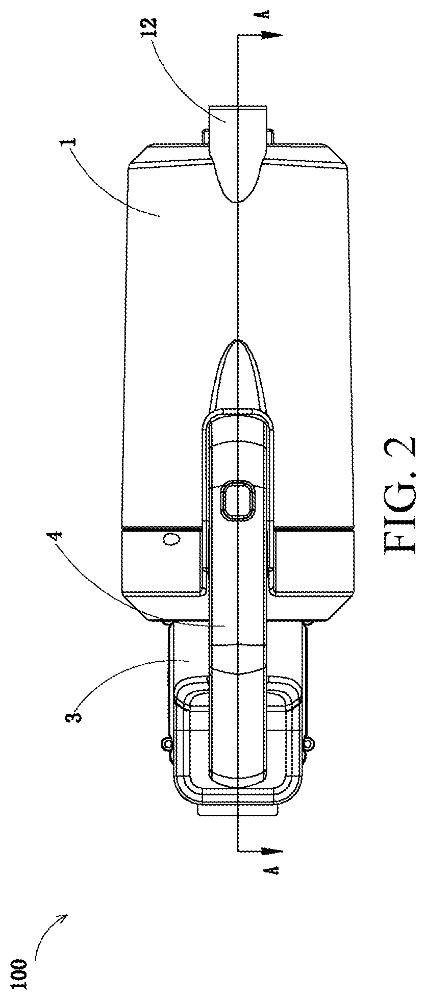
[0057] FIG. 2 is a schematic diagram of FIG. 1 from another angle.
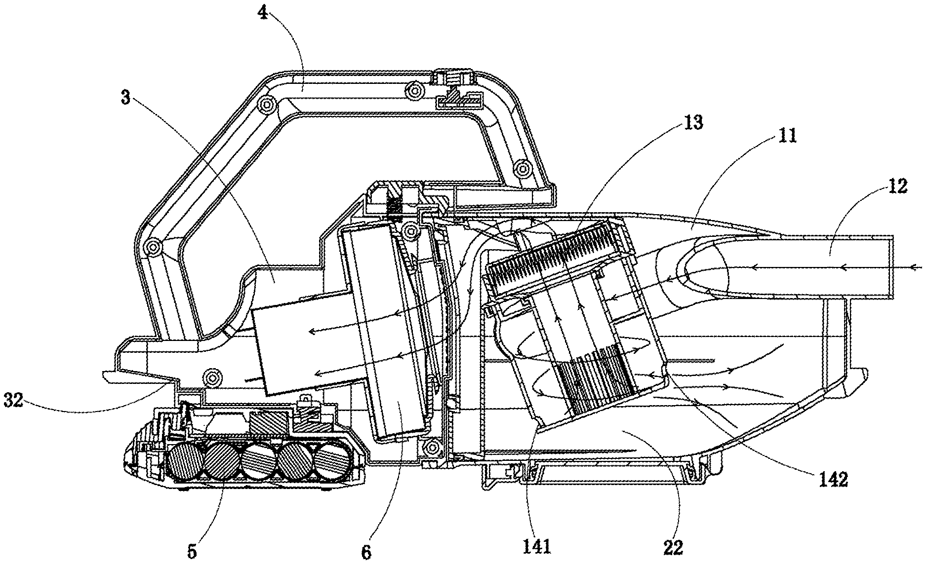
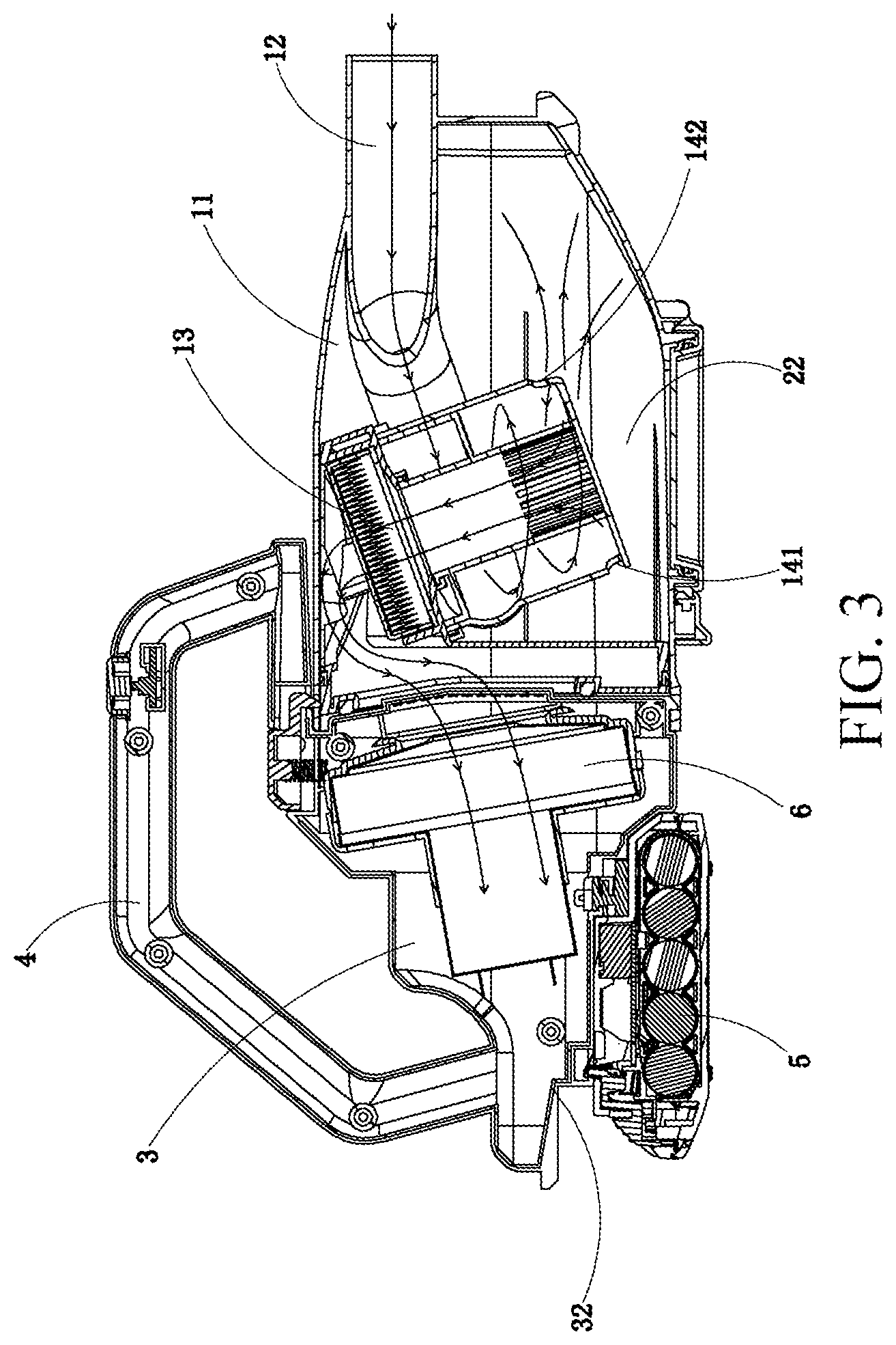
[0058] FIG. 3 is a sectional view along a line A-A in FIG. 2, indicating a flow direction of an air channel;
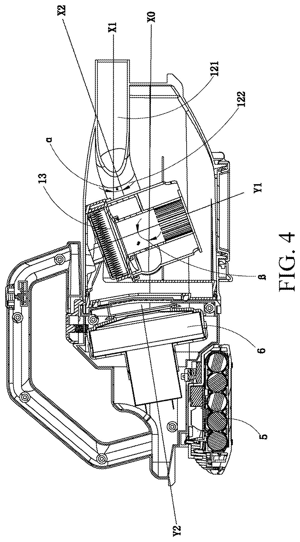
[0059] FIG. 4 is a sectional view along a line A-A in FIG. 2, indicating various axes;
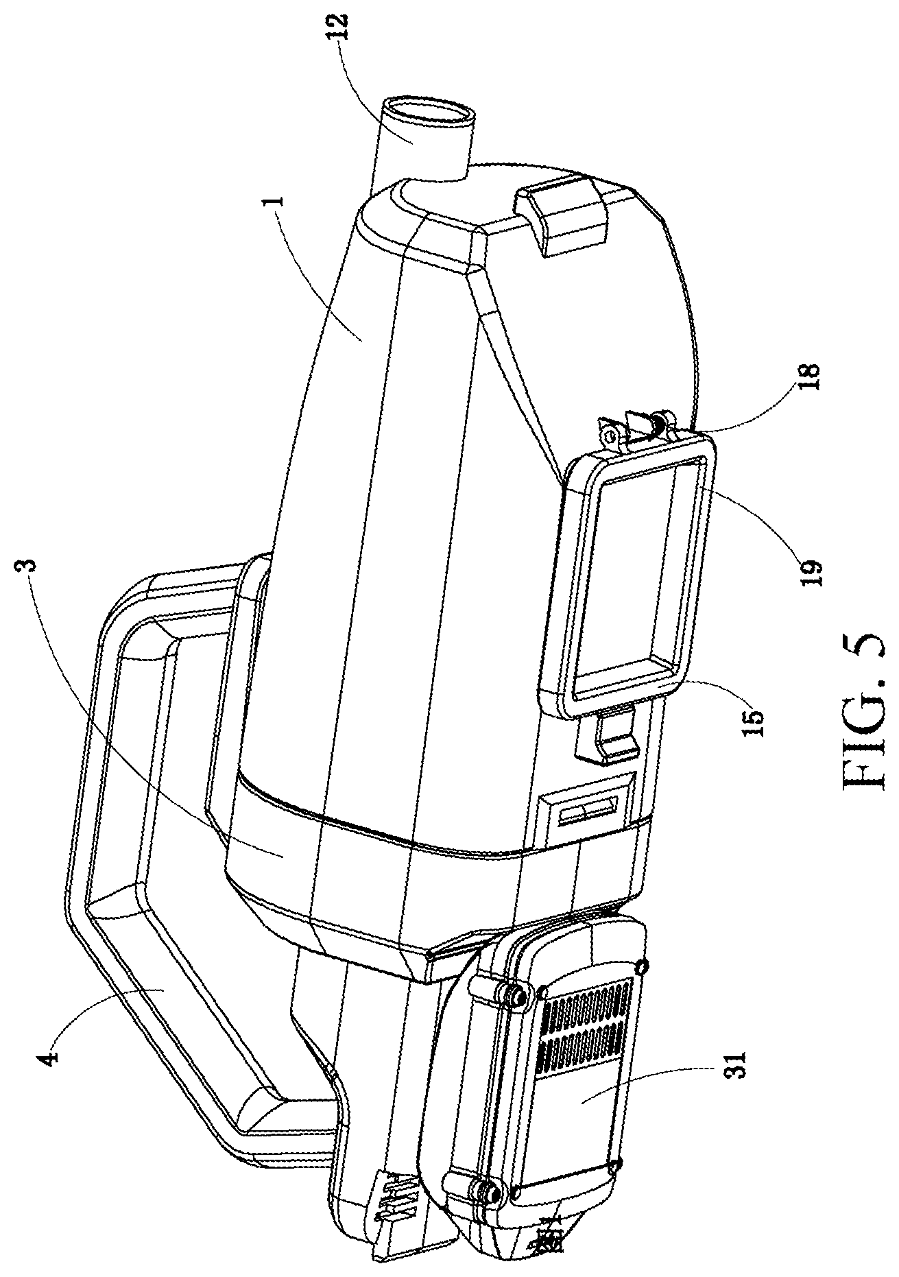
[0060] FIG. 5 is a schematic diagram showing that a dust cup cover is closed in the handheld vacuum cleaner according to the first embodiment of the present invention;
[0061] FIG. 6 is a schematic diagram showing that a dust cup cover is open in the handheld vacuum cleaner according to the first embodiment of the present invention;
[0062] FIG. 7 is an exploded view of a filter apparatus in the handheld vacuum cleaner from an angle according to the first embodiment of the present invention;
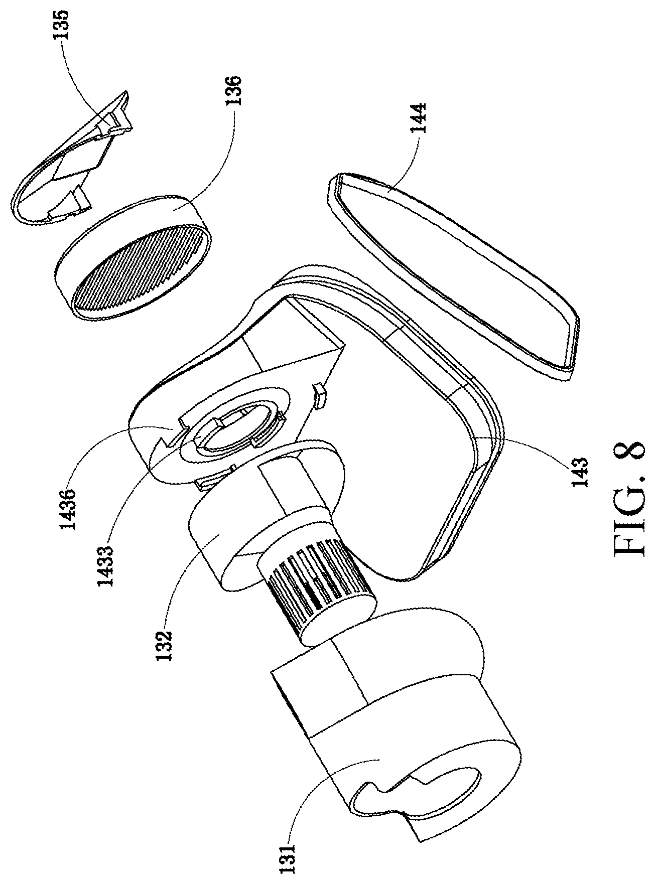
[0063] FIG. 8 is an exploded view of a filter apparatus in the handheld vacuum cleaner from another angle according to the first embodiment of the present invention;
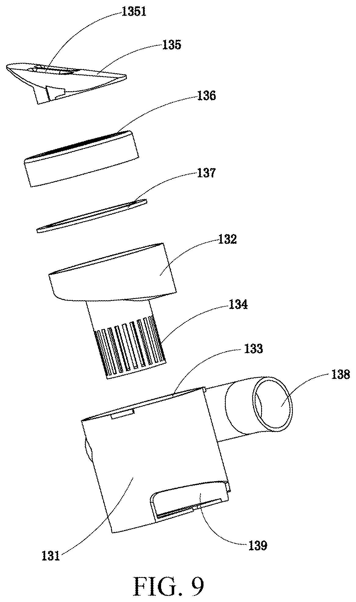
[0064] FIG. 9 is an exploded view of the filter apparatus without a positioning plate in the handheld vacuum cleaner according to the first embodiment of the present invention;
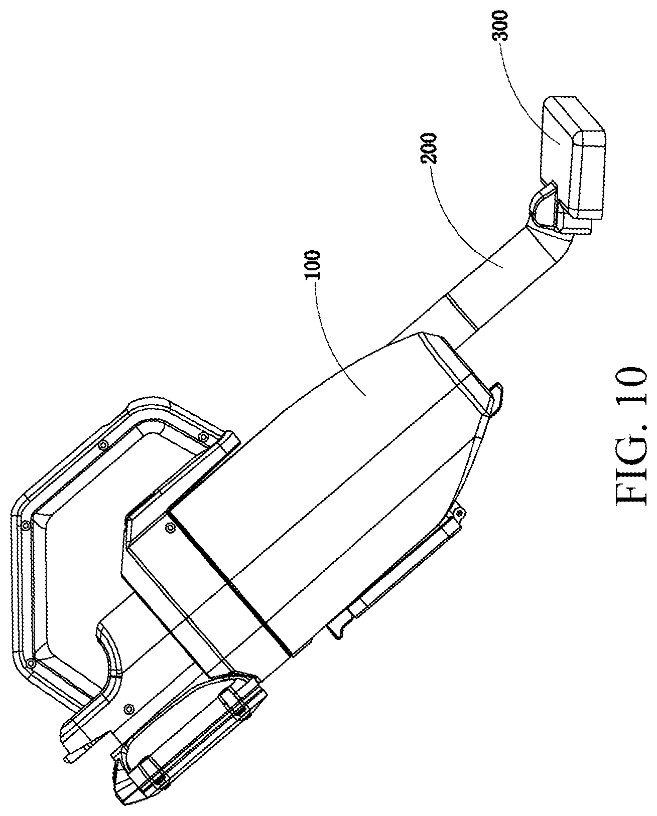
[0065] FIG. 10 is a schematic diagram of a working state of the handheld vacuum cleaner according to the first embodiment of the present invention;
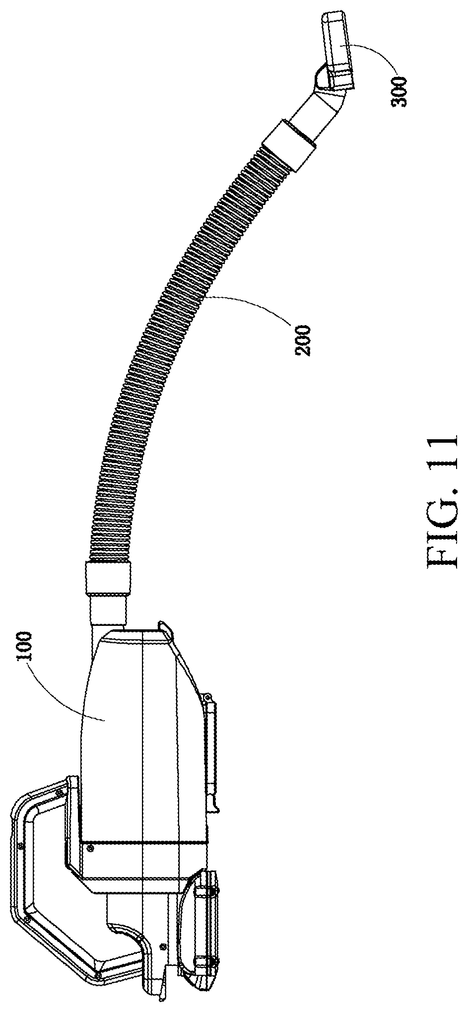
[0066] FIG. 11 is a schematic diagram of another working state of the handheld vacuum cleaner according to the first embodiment of the present invention;
[0067] FIG. 12 is a schematic diagram of a stick vacuum cleaner according to a first embodiment of the present invention;
[0068] FIG. 13 is a schematic diagram of a dust bin according to a first embodiment of the present invention;
[0069] FIG. 14 is a schematic diagram of a base portion of the dust bin according to the first embodiment of the present invention;
[0070] FIG. 15 is a top view of FIG. 14;
[0071] FIG. 16 is a schematic diagram of a top portion of the dust bin according to the first embodiment of the present invention;
[0072] FIG. 17 is a top view of FIG. 16;
[0073] FIG. 18 is a bottom view of FIG. 16;
[0074] FIG. 19 is a front view of FIG. 16;
[0075] FIG. 20 is a schematic diagram of a first state of the dust bin according to the first embodiment of the present invention;
[0076] FIG. 21 is a top view of FIG. 20;
[0077] FIG. 22 is a schematic diagram of a second state of the dust bin according to the first embodiment of the present invention;
[0078] FIG. 23 is a schematic three-dimensional diagram of a dust bin according to a second embodiment of the present invention;
[0079] FIG. 24 is a top view of FIG. 23;
[0080] FIG. 25 is a schematic three-dimensional diagram of the first state of the dust bin in the first embodiment in a handheld vacuum cleaner combination according to a first embodiment of the present invention;
[0081] FIG. 26 is a top view of FIG. 25;
[0082] FIG. 27 is a sectional view of FIG. 25;
[0083] FIG. 28 is a schematic three-dimensional diagram showing that the dust cup cover is open in the second state of the dust bin in the first embodiment in the handheld vacuum cleaner combination according to the first embodiment of the present invention;
[0084] FIG. 29 is a schematic three-dimensional diagram showing that the dust cup cover is closed in the second state of the dust bin in the first embodiment in the handheld vacuum cleaner combination according to the first embodiment of the present invention;
[0085] FIG. 30 is a sectional view of FIG. 29;
[0086] FIG. 31 is a schematic three-dimensional diagram of a third state of the dust bin in the first embodiment in the handheld vacuum cleaner combination according to the first embodiment of the present invention;
[0087] FIG. 32 is a sectional view of FIG. 31;
[0088] FIG. 33 is a schematic three-dimensional diagram of the dust bin in the second embodiment in a handheld vacuum cleaner combination according to a second embodiment of the present invention;
[0089] FIG. 34 is a sectional view of FIG. 33;
[0090] FIG. 35 is a schematic diagram of a working state of the handheld vacuum cleaner combination according to the first embodiment of the present invention;
[0091] FIG. 36 is a schematic diagram of a working state of the handheld vacuum cleaner combination according to the second embodiment of the present invention;
[0092] FIG. 37 is a schematic diagram of a handheld vacuum cleaner according to a second embodiment of the present invention;
[0093] FIG. 38 is a schematic diagram of a working state of a handheld vacuum cleaner combination according to a third embodiment of the present invention;
[0094] FIG. 39 is a schematic diagram of a working state of a handheld vacuum cleaner combination according to a fourth embodiment of the present invention;
[0095] FIG. 40 is a schematic diagram of a handheld vacuum cleaner according to a third embodiment of the present invention;
[0096] FIG. 41 is a schematic diagram of a working state of a handheld vacuum cleaner combination according to a fifth embodiment of the present invention;
[0097] FIG. 42 is a schematic diagram of a working state of a handheld vacuum cleaner combination according to a sixth embodiment of the present invention;
[0098] FIG. 43 is a working schematic diagram of a stick vacuum cleaner according to a second embodiment of the present invention;
[0099] FIG. 44 is a working schematic diagram of a stick vacuum cleaner according to a third embodiment of the present invention;
[0100] FIG. 45 is a working schematic diagram of a stick vacuum cleaner according to a fourth embodiment of the present invention;
[0101] FIG. 46 is a working schematic diagram of a stick vacuum cleaner according to a fifth embodiment of the present invention;
[0102] FIG. 47 is a working schematic diagram of a stick vacuum cleaner according to a sixth embodiment of the present invention;
[0103] FIG. 48 is a working schematic diagram of a stick vacuum cleaner according to a seventh embodiment of the present invention;
[0104] FIG. 49 is schematic diagram of a first gripping scenario of a handle assembly according to the present invention;
[0105] FIG. 50 is schematic diagram of a second gripping scenario of a handle assembly according to the present invention;
[0106] FIG. 51 is schematic diagram of a third gripping scenario of a handle assembly in the present invention;
[0107] FIG. 52 is schematic diagram of a fourth gripping scenario of a handle assembly according to the present invention;
[0108] FIG. 53 is a schematic diagram of the handheld vacuum cleaner sucking water according to the present invention;
[0109] FIG. 54 is a schematic diagram of the handheld vacuum cleaner according to the second embodiment of the present invention;
[0110] FIG. 55 is a sectional view of a dust cup assembly in FIG. 54;
[0111] FIG. 56 is a sectional view of a dust cup assembly in FIG. 54 from another angle;
[0112] FIG. 57 is a schematic three-dimensional diagram of a filter in FIG. 54;
[0113] FIG. 58 is a schematic three-dimensional diagram of a cyclone separator in FIG. 54;
[0114] FIG. 59 is a schematic sectional view of the cyclone separator in FIG. 58;
[0115] FIG. 60 is a schematic diagram of the handheld vacuum cleaner according to the third embodiment;
[0116] FIG. 61 is a schematic diagram of a handheld vacuum cleaner according to the fourth embodiment;
[0117] FIG. 62 is a schematic diagram of the handheld vacuum cleaner in FIG. 61 combined with a dust bin;
[0118] FIG. 63 is a schematic diagram of a handheld vacuum cleaner according to the fifth embodiment;
[0119] FIG. 64 is a schematic diagram of the handheld vacuum cleaner in FIG. 63 combined with a dust bin;
[0120] FIG. 65 is a sectional view of FIG. 64;
[0121] FIG. 66 is a schematic diagram of an airflow direction in the handheld vacuum cleaner in FIG. 63;
[0122] FIG. 67 is a schematic diagram of the sectional view in FIG. 64 with size marks;
[0123] FIG. 68 is a schematic diagram of an airflow direction in the handheld vacuum cleaner in a first working mode according to a sixth embodiment;
[0124] FIG. 69 is a structural sectional view of a dust cup assembly in FIG. 66;
[0125] FIG. 70 is a schematic diagram of an airflow direction in a second embodiment in the handheld vacuum cleaner according to the sixth embodiment; and
[0126] FIG. 71 is a schematic diagram of the handheld vacuum cleaner according to the sixth embodiment combined with a dust bin.
DETAILED DESCRIPTION
[0127] The present invention discloses a vacuum cleaner combination, including a dust suction apparatus and a dust bin that is combined with the dust suction apparatus to collect dust sucked by the dust suction apparatus. The vacuum cleaner combination is operable in and a second working mode. In the first working mode, the dust suction apparatus is not coupled to the dust bin, and the dust suction apparatus independently works and is responsible for dust suction and dust collection. In the second working mode, the dust suction apparatus is coupled to the dust bin. The dust suction apparatus is only responsible for dust suction, and the dust bin is responsible for dust collection. The dust suction apparatus has a first dust collection capacity, and the dust bin has a second dust collection capacity. In the first working mode, a dust collection capacity is the first dust collection capacity. In the first working mode, the dust collection capacity is the sum of the first dust collection capacity and the second dust collection capacity. Specifically, in the first working mode, the dust collection capacity is A, where A is the dust collection capacity of the dust suction apparatus. In the second working mode, the dust collection capacity is A+B, where B is the dust collection capacity of the dust bin. The dust bin is disposed, so that the dust collection capacity is increased, and no additional dust collection channel is required. In addition, mode switching is simple and easy, and it is not necessary to detach an original dust cup assembly. A dust bin detachable from a dust suction apparatus is disposed, so that a dust collection chamber of a vacuum cleaner is flexibly increased. The dust bin has a simple structure, and is combined with the dust suction apparatus to form a compact structure and occupy a small space, so as to meet cleaning requirements of scenarios with different amounts of dust. For a scenario with a small amount of dust, for example, a domestic scenario, the dust suction apparatus may be separately used. The dust suction apparatus may be a handheld vacuum cleaner or may be a horizontal vacuum cleaner or another vacuum cleaner that is suitable for domestic use and can be combined with a dust bin through a structural design. For a scenario with a large amount of dust, for example, a garage or an outdoor area with a large amount of dust, a dust bin may be used to accommodate dust, to reduce the frequency of dumping dust by a user. When a dust bin is used in a garage or an outdoor area, a roller may be disposed at the bottom of the dust bin. In this way, it is convenient for a user to directly pull the dust bin without needing to lift it, thereby improving user experience and use convenience.
[0128] The dust bin includes a dust chamber and a dust inlet in communication with the dust chamber. In the second working mode, the dust inlet receives dust passing through the dust suction apparatus. The dust bin is disposed to be detachable from the dust suction apparatus, so that a dust collection chamber of a vacuum cleaner is flexibly increased. The dust bin has a simple structure. After the dust bin is joined to the dust suction apparatus, the structure is compact and occupies a small space, and the cleaning requirements of scenarios with different amounts of dust can be met. For a scenario with a small amount of dust such as a domestic scenario, the dust suction apparatus may be used alone. The dust suction apparatus may be a handheld vacuum cleaner, a horizontal vacuum cleaner or another vacuum cleaner that is suitable for domestic use and can be joined to the dust bin through structural design. For a scenario with a large amount of dust such as a garage or an outdoor space with a large amount of dust, the dust bin may be used to accommodate dust and dust, so as to reduce the frequency of dumping dust by a user. If the dust bin is used in a garage or an outdoor space, rollers may be disposed under the dust bin, so that the user can directly pull the dust bin without lifting the dust bin, thereby enhancing the user experience and facilitate the use of the dust bin.
[0129] The dust suction apparatus includes a dust cup assembly and a motor assembly. The motor assembly includes a motor and a fan, and the motor drives the fan to rotate to form a negative pressure in the dust cup assembly. The dust cup assembly includes a cup body, a filter apparatus disposed in the cup body, a dust outlet for emptying debris, and a dust cup cover for sealing the dust outlet. The dust outlet is located opposite and combined with the dust inlet in the second working mode. The dust outlet is located opposite and combined with the dust inlet in the working mode and the transport/storage mode. The dust bin has an abutting portion that controls the dust cup cover to automatically open. The abutting portion is disposed, so that the dust cup cover can automatically open without a separate operation of a user when the dust bin is combined with the dust suction apparatus, thereby improving the use convenience.
[0130] In the description of the following embodiments of the present invention, the "dust" refers to different substances in different use scenarios rather than dust in the literal sense. For example, in an indoor domestic scenario, "dust" may be powder, bread crumbs, cookie crumbs, mud, rice grains, clean water spilled on the floor, dirty water or the like. In a garage environment or a scenario with dust in a large area, "dust" may be sawdust, dirt, dirty water or the like. The "dust" represents different substances in different use scenarios, including, but not limited to, the foregoing examples.
[0131] To make the objectives, technical solutions, and advantages of the present invention clearer, the present invention is further described in detail below with reference to the accompanying drawings and the embodiments. It should be understood that the specific embodiments described herein are merely used to explain the present invention, but are not intended to limit the present invention. The dust suction apparatus may be a household vacuum cleaner that can be joined to a dust bin through structural design such as a handheld vacuum cleaner and a horizontal vacuum cleaner. The following embodiments are described with a handheld vacuum cleaner as an example, and the description of the embodiments of the handheld vacuum cleaner is also applicable to the horizontal vacuum cleaner and other household vacuum cleaners that can be joined to a dust bin.
[0132] As shown in FIG. 1 to FIG. 6, a handheld vacuum cleaner 100 is provided in a first embodiment of the present invention, and a filter apparatus is disposed obliquely in this embodiment. Specifically, the handheld vacuum cleaner 100 includes a dust cup assembly 1, a housing 3 connected to the dust cup assembly 1, a handle assembly 4 disposed on the housing 3 and used for gripping, a battery assembly 5 disposed below the handle assembly 4 and used for supplying electricity to the handheld vacuum cleaner 100, and an air flow generator 6 used for supplying power to the handheld vacuum cleaner 100 and generating a negative pressure for vacuuming. The air flow generator 6 is disposed in the housing 3. The handheld vacuum cleaner 100 has a first positioning buckle 20 and a second positioning buckle 21 that are respectively located at two ends of the handheld vacuum cleaner 100. The battery assembly 4 is disposed below and behind the air flow generator 5. The dust cup assembly 1 may be fastened to the housing 3 by a buckle structure, or an end of the dust cup assembly 1 is disposed to be cylindrical and the dust cup assembly 1 and the housing 3 are provided with rotating threads to fasten the dust cup assembly 1 to the housing 3 by the rotating threads.
[0133] As shown in FIG. 1 to FIG. 6, the dust cup assembly 1 is provided with a dust suction inlet 12 configured to guide an external airflow into a handheld vacuum cleaner 100. The housing 3 is provided with an air flow outlet 32. An air flow path is formed between the dust suction inlet 12 and the air flow outlet 32. An air flow flows from the dust suction inlet 12, passes through the dust cup assembly 1 and the air flow generator 6 in sequence, and eventually leaves the air flow outlet 32.
[0134] As shown in FIG. 3 to FIG. 6, in an embodiment of the present invention, the dust cup assembly 1 includes a cup body 11, a filter apparatus 13 disposed in the cup body 11, a dust outlet 14 disposed on the cup body 11, a dust cup cover 15 for sealing the dust outlet 14, a latching portion 16 for controlling the dust cup cover 15 to be opened or locked, a rotating portion 17, and a reset structure 18. When the latching portion 16 controls the dust cup cover 15 to be opened or locked, the dust cup cover 15 rotates around the rotating portion 17, and when the dust cup cover 15 is unlocked, the dust cup cover 15 is driven by the reset structure 18 to automatically open. The dust cup cover 15 opens at an angle ranging from 110 degrees to 190 degrees. The reset structure 18 is disposed, so that one-push dumping can be implemented without needing to manually open the dust cup cover 15 for dumping, to make the operation convenient and quick. In an embodiment of the present invention, as shown in FIG. 7, the reset structure 18 is a torsion spring structure. Certainly, in other embodiments, a person skilled in the art may use other reset structures that can achieve the objectives of the present embodiment. An outer periphery of the dust cup cover 15 or the dust outlet 14 is provided with a second sealing member (not shown in the figure) for sealing the dust outlet 14 and the dust cup cover 15.
[0135] As shown in FIG. 7 to FIG. 9, in the embodiments of the present invention, the filter apparatus 13 is a filter apparatus using a cyclone separator. The filter apparatus 13 includes a positioning plate 143, a main body portion 131 fastened to the positioning plate 143, a cyclone 132 fastened to the positioning plate 143 and located in the main body portion 131, a filter 136, a cover plate 135 that is pressed against the filter 136 to position the filter 136, and a sealing ring 137 for sealing the filter 136 to prevent dust from leaving from an outer edge of the filter 136. The positioning plate 143 has a first fastening body 1431 and a second fastening body 1432 integrally connected to an end of the first fastening body 1431. The first fastening body 1431 is connected to the cup body 11, and the first fastening body 1431 is provided with a fastening sealing ring 144. The fastening sealing ring 144 is disposed to ensure the fastened sealing performance between the first fastening body 1431 and the cup body 11. In this embodiment, the first fastening body 1431 and the second fastening body 1432 are an integral structure. In other embodiments, the first fastening body 1431 and the second fastening body 1432 may be implemented by using a split assembly structure. For example, the two parts are fastened by insertion or buckling or gluing. In this embodiment, the filter 136 is a waterproof filter, for example, a waterproof HEPA filter.
[0136] As shown in FIG. 7 to FIG. 9, in the embodiments of the present invention, the second fastening body 1432 has a receiving hole 1435 for receiving the filter 136, a first positioning portion 1433 for fastening the cyclone 132, a second positioning portion 1434 for fastening the main body portion 131, and a third positioning portion 1436 for fastening the cover plate 135. A top portion of the cover plate 135 is provided with an air outlet 1351 and a fourth positioning portion 1437 buckled with the third positioning portion 1436. The mounting relationships between all the structures of the dust cup assembly 1 are as follows: The cyclone 132 is first fastened to the second fastening body 1432 by the first positioning portion 1433. The main body portion 131 is then fastened to the second fastening body 1432 by the second positioning portion 1434. The filter 136 is then placed in the receiving hole 1435. The sealing ring 137 is placed between the filter 136 and the second fastening body 1432 and implements sealing in a circumferential direction to prevent dust from flying out of the filter 136 in the circumferential direction. The cover plate 135 is then pressed against the filter 136 and is fastened to the second fastening body 1432 by the combination of the third positioning portion 1436 and the fourth positioning portion 1437, and the filter 136 is further positioned. An air flow obtained by cyclonic separation flows from the air outlet 1351 to the air flow generator 6. In the embodiments shown in the accompanying drawings of the present embodiment, the first fastening body 1431 intersects with and is approximately perpendicular to the second fastening body 1432. The angle between the first fastening body 1431 and the second fastening body 1432 is not explicitly limited, and any angle is feasible provided that structures such as the cyclone 136 are conveniently mounted.
[0137] As shown in FIG. 7 to FIG. 9, the main body portion 131 is provided with a separation inlet 138 connected to the dust suction inlet 12 and a separation outlet 139 for throwing dust out of the main body portion 131. The cyclone 132 is provided with several pores 134 for a cyclonic air flow to pass through. A cyclone chamber 133 is defined in the main body portion 131. On the air flow path, the filter 136 is located downstream of the cyclone 132. A dusty air flow enters the main body portion 131 through the separation inlet 138, cyclonic separation is performed on the dusty air flow in the cyclone chamber 133, dust is thrown out through the separation outlet 139 and collected in the dust cup assembly 1, the filtered air flow containing a small amount of dust then flows to the filter 136 through the pores 134 for re-filtration, and the air flow re-filtered by the filter 136 passes through the air flow generator 6 to be discharged from the air flow outlet 32.
[0138] As shown in FIG. 4, the cup body 11 includes a longitudinal axis X0 extending longitudinally, and the longitudinal axis X0 is a length direction of the handheld vacuum cleaner. The filter apparatus 13 is provided with a first axis Y1 extending longitudinally, the filter apparatus 13 is disposed obliquely relative to the longitudinal axis X0, and there is an acute angle between the longitudinal axis X0 and the first axis Y1. The filter apparatus 13 is disposed obliquely, so that compared with a vertically placed filter apparatus in the prior art, the height of the entire machine is reduced, and compared with a horizontally placed filter apparatus in the prior art, the length of the entire machine is reduced, so that the vacuum cleaner has a compact structure, a small size, and a light weight, and meets the current market demand for lightweight and miniaturized vacuum cleaners. Moreover, the filter apparatus 13 is disposed obliquely, so that compared with a horizontally placed filter apparatus with a same or similar structure in the prior art, when dusty liquid is collected, the separation outlet 139 may be disposed at a higher position, and compared with a horizontally placed filter apparatus in the prior art, the position of the separation outlet 139 of the filter apparatus 13 may be raised to prevent dusty liquid from being drawn into the cyclone chamber again to avoid blockage of the filter 136, prolong the service life of the filter 136, and prevent moisture in the liquid from entering the air flow generator to protect electrical parts from damage.
[0139] As shown in FIG. 4, the filter apparatus 13 extends obliquely downward toward the dust suction inlet 12 as viewed in a flow direction of the air flow. The angle between the longitudinal axis X0 and the first axis Y1 is in principle greater than 0 degrees and less than 90 degrees. In the preferred embodiments of the present invention, the angle between the longitudinal axis X0 and the first axis Y1 is between 30 degrees and 60 degrees. In this preferred angle range, the entire machine has a small structure, and the effect of cyclonic separation and the dust removal performance of the entire machine can be ensured.
[0140] As shown in FIG. 3 to FIG. 9, a dust collection chamber 22 is formed in the cup body 11, and the separation outlet 139 is in communication with the dust collection chamber 22. The dust collection chamber 22 is used to collect dust obtained after cyclonic separation in the filter apparatus in the presentembodiment. The filter apparatus 13 is disposed obliquely relative to the cup body 11 having the dust collection chamber 22. If a vacuum cleaner has a plurality of filter apparatuses and the plurality of filter apparatuses have a plurality of dust accommodation cavities independent of each other, the body forming the dust collection chamber may be considered as the cup body in the presentembodiment. That is, if a vacuum cleaner has a plurality of filter apparatuses and the plurality of filter apparatuses have a plurality of independent dust accommodation cavities, it may be considered that the vacuum cleaner has a plurality of cup bodies according to the presentembodiment, and the filter apparatus is disposed obliquely relative to an axis of the cup body in which the filter apparatus is located. Certainly, in another case in which there is only one dust collection chamber, a vacuum cleaner has one cup body in the presentembodiment, and the filter apparatus is disposed obliquely relative to an axis of the independent cup body. In the presentembodiment, the filter apparatus is disposed obliquely. From another angle, if a bottom surface of the vacuum cleaner is parallel to a horizontal plane and the vacuum cleaner is placed in the horizontal plane, the filter apparatus is oblique relative to the horizontal plane.
[0141] As shown in FIG. 3 to FIG. 9, when a dusty air flow swirls in the cyclone chamber 133, the separated dust is thrown out of the separation outlet 139 under the action of the air flow and accumulated in the dust collection chamber 22. The dust collection chamber 22 is located outside the filter apparatus 13. That is, the dust collection chamber 22 is in communication with but spatially separated from the cyclone chamber 133. This design can prevent dust from drawn back into the filter apparatus 13 by the flowing air flow, thereby effectively improving the separation effect of the dusty air flow and avoiding blockage of the filter 136.
[0142] As shown in FIG. 3, from an angle of the dust collection chamber 22, after the filter apparatus 13 is disposed obliquely, a low point 141 near the dust collection chamber and a high point 142 far away from the dust collection chamber 25 relative to the low point 141 are formed at an end, adjacent to the dust collection chamber 22, of the filter apparatus 13, and the separation outlet 139 is disposed at the high point 142. The filter apparatus 13 is disposed obliquely, so that as compared with a horizontally placed filter apparatus with a same or similar structure in the prior art, when dusty liquid is collected, this design may increase a dust collection space, and the separation outlet 139 is disposed at the high point to raise the position of the separation outlet 139 of the filter apparatus 13, which can prevent dusty liquid from being drawn into the cyclone chamber again to avoid blockage of the filter, prolong the service life of the filter, and prevent moisture in the liquid from entering into the air flow generator to protect electrical parts from damage.
[0143] In the embodiments of the present invention, the cyclone 132 is a one-stage cyclone structure, and dust in a dusty air flow entering the main body portion 131 can be centrifugally thrown out in a cyclonic manner in the cyclone chamber 133, thereby further improving the dust removal effect. In other embodiments, the cyclone 132 may be a multi-stage cyclone structure. That is, in the flow direction of the air flow, the cyclone chamber 133 includes a plurality of cyclone chambers that are sequentially connected. In this way, a dusty air flow entering the main body portion 131 can pass through the plurality of cyclone chambers in sequence for repeated dust and air separation, thereby improving the dust removal effect.
[0144] As shown in FIG. 5, a bottom surface 19 is located below the dust cup assembly 1, a support surface 31 is located below the battery assembly 5, and the bottom surface 19 is coplanar with the support surface 31. In this way, the dust cup assembly 1 and the battery assembly 5 together support the entire machine, so that the entire machine is relatively stably placed, and does not tilt or fall. The foregoing coplanar design is a preferred embodiment of the present invention, and in other embodiments, due to the weight and placement angle of the air flow generator 6, the center of gravity of the entire machine tends to be at the rear part of the entire machine. In this case, the dust cup assembly 1 is not necessarily required to support the entire machine, so that the bottom surface 19 may be non-coplanar with the support surface 31.
[0145] As shown in FIG. 4 and FIG. 6, the dust suction inlet 12 includes a first flow-directing section 121 and a second flow-directing section 122 connected to the first flow-directing section 121. In the embodiments in the accompanying drawings of the present invention, the first flow-directing section 121 is formed on the cup body 11, and the second flow-directing section 122 is formed on the main body portion 131. Since the first flow-directing section 121 and the second flow-directing section 122 connected thereto are separately formed on two components, the first flow-directing section 121 may be connected to the second flow-directing section 122 by a fastening structure or by a mutual fit between the first flow-directing section 121 and the second flow-directing section 122. In other embodiments of the present invention, the first flow-directing section 121 in direct and proximate communication with the outside and the second flow-directing section 122 connected to the first flow-directing section 121 may be directly formed on the cup body 11, and the cup body 11 is then connected to the main body portion 131 by the second flow-directing section 122. In the embodiments in which both the first flow-directing section 121 and the second flow-directing section 122 are disposed on the cup body 11, the first flow-directing section 121 and the second flow-directing section 122 may be an integrally formed structure or may be two separate structures that are combined with each other.
[0146] As shown in FIG. 4, the first flow-directing section 121 has a first intake axis X1, the second flow-directing section 122 has a second intake axis X2, and an angle .alpha. between the first intake axis X1 and the second intake axis X2 plus an angle .beta. between the first axis Y1 and the longitudinal axis X0 is equal to 90 degrees. That is, the sum of the two angles is 90 degrees. Since an air flow tangentially enters the filter apparatus 13 and the filter apparatus 13 is disposed obliquely, a direction of the separation inlet 138 changes accordingly, and an air flow guided by the dust suction inlet 12 needs to be tilted and steered to enter the separation inlet 138.
[0147] As shown in FIG. 4, the relationship between the first flow-directing section 121 and the filter apparatus 13 is as follows: The first intake axis X1 intersects with and is not perpendicular to the first axis Y1, and an angle between the intake axis X1 and the first axis Y1 ranges from 30 degrees to 60 degrees. In the embodiments of the present invention, for the consistency of reference standard, the first intake axis X1 is parallel to the longitudinal axis X0. With the same standard, an angle of inclination of the filter apparatus 12 and an angle of rotation of the second flow-directing section 24 can be accurately designed.
[0148] The inclination direction of the filter apparatus 13 may be defined by the angular relationship between the first axis Y1 and the longitudinal axis X0 as described above. On the premise that the filter apparatus 13 is disposed obliquely relative to the longitudinal axis X0, the positional relationship between the filter apparatus 12 and other components is described in detail below.
[0149] As shown in FIG. 4, the air flow generator 6 extends obliquely relative to the longitudinal axis X0 of the dust cup assembly 1, specifically, the air flow generator 6 is provided with a second axis Y2, the air flow generator 6 is disposed obliquely relative to the longitudinal axis X0, and there is an acute angle between the second axis Y2 and the longitudinal axis X0. In the preferred embodiments of the present invention, an angle between the longitudinal axis X0 and the first axis Y2 ranges from 5 degrees to 30 degrees. The filter apparatus 13 also extends obliquely relative to the air flow generator 6. Specifically, an angle between the first axis Y1 and the second axis Y2 ranges from 60 degrees to 85 degrees.
[0150] As shown in FIG. 4, since the filter apparatus 13 is disposed obliquely, if the air flow generator 6 is placed at the original angle, the length of an air flow channel between the filter apparatus 13 and the air flow generator 6 is prolonged. To reduce the channel length and enable the air flow separated by the filter apparatus 13 to quickly enter the air flow generator 6, the air flow generator 6 is also disposed obliquely. The air flow generator 6 extends obliquely upward toward the filter 136, so as to reduce the length of the air flow channel between the filter apparatus 13 and the air flow generator 6.
[0151] As shown in FIG. 3 and FIG. 4, the air flow generator 6 extends obliquely upward, the air flow generator 6 may be considered to be placed horizontally and extend obliquely upward, and an upward inclination angle of the air flow generator 6 is related to the inclination angle of the filter apparatus 13. Considering from two aspects, that is, an air channel between the filter apparatus 13 and the air flow generator 6 is the shortest and a volume of the entire machine is not affected, an appropriate inclination angle of the air flow generator 6 is selected. In other embodiments of the present invention, instead of being disposed obliquely, the air flow generator 6 is placed horizontally. If the air flow generator 6 is placed vertically, the height of the entire handheld vacuum cleaner 100 is increased. When the air flow generator 6 is placed horizontally, an increase in the height of the entire handheld vacuum cleaner 100 can be avoided. As shown in FIG. 5, in the embodiments of the present invention, the battery assembly 5 may be placed in a space defined after the air flow generator 6 is disposed obliquely. In this way, the space is appropriately utilized, so as to further reduce the length of the entire handheld vacuum cleaner 100, thereby reducing the volume of the entire machine.
[0152] The air flow generator 6 includes a rotating shaft (not shown in the figure) and a rotatable impeller (not shown in the figure) disposed on the rotating shaft. When the air flow generator 6 is working, the rotating shaft drives the impeller to rotate to generate strong suction and pressure. Under the action of suction and pressure, an air flow flowing through the air flow generator 6 is discharged at a high speed, and an air flow at an air inlet end of the air flow generator 6 is continuously filled to the air flow generator 6, resulting in an instantaneous vacuum inside the housing 3, so that an external dusty air flow can be drawn into the dust cup assembly 1 through the dust suction inlet 12. When the handheld vacuum cleaner 200 is working, a dusty air flow entering from the dust suction inlet 10 first enters the filter apparatus 13 for filtration, and dust and dirt removed through filtering are kept in the cup body 11. Air filtered by the filter apparatus 13 is then re-filtered by the filter 136 to filter out dust and moisture again, and air re-filtered by the filter 136 flows to the air flow generator 6. The air can cool the air flow generator 6 in the process of flowing to the air flow generator 6, thereby prolonging the service life of the air flow generator 6. Next, the air is discharged from the air flow outlet 32 to the outside of the housing 3.
[0153] As shown in FIG. 4, in the embodiments in the accompanying drawings of the present invention, the filter 136 is located between the cyclone 132 and the air flow generator 6. The cyclone 132 is disposed upstream of the filter 136, and the cyclone 132 pretreats dry and wet dusty air flows, so that only air flows with a relatively small of dust flows through the filter 136, thereby avoiding blockage of the filter 136, prolonging the service life of the filter 136, and improving the dust removal performance. In the preferred embodiments of the present invention, the filter 136 is a waterproof HEPA filter. Since the handheld vacuum cleaner 100 in the present invention can be used as a vacuum cleaner for use in both a wet scenario and a dry scenario, dust may be dust with the properties of a liquid. With the waterproof function, moisture is prevented from entering the air flow generator 6, thereby protecting electrical devices from damage. In other embodiments, instead of being limited to a waterproof HEPA filter, the filter 136 may be another filtering structure, for example, a multi-stage filtering structure that is combined with or integrally formed with the filter apparatus 13 and provides two-stage filtering. Dust and impurities can be adequately removed through multi-stage filtration. When the present invention is applied to wet treatment, for example, water absorption, in addition to the waterproof design of the filter 136 and the liquid treatment of the cyclone 132, the electrical devices such as the air flow generator 6 may also be waterproofed to further protect the electrical devices, thereby eventually ensuring the working stability and safety of liquid treatment of the vacuum cleaner.
[0154] As shown in FIG. 1, the handle assembly 4 is provided with two ends extending from front to back, namely, a first end 41 and a second end 42. The first end 41 is close to the cup body 11 and located above the cup body 11. The second end 42 is located behind the housing 11 and close to the air flow generator 6. Because the air flow generator 6 is adjacent to the battery assembly 5, the second end 42 is also close to the battery assembly 5 and located above the battery assembly 5. The handle assembly 4 is disposed to extend from front to back, so that when a user grips the handle to lift the machine, the user applies a force properly and use the machine comfortably. In addition, since the filter apparatus 13 is disposed obliquely in the presentembodiment, the handle assembly 4 is not designed to be D-shaped, thereby further reducing the height of the entire handheld vacuum cleaner 100.
[0155] As shown in FIG. 1, in the handheld vacuum cleaner 100 in this embodiment, the handle assembly 4 includes a horizontal gripping area 43 and an oblique gripping area 44 connected to the horizontal gripping area 43, and the horizontal gripping area 43 and the oblique gripping area 44 form a V shape. The horizontal gripping area 43 is connected to the first end 41, the oblique gripping area 44 is connected to the horizontal gripping area at an obtuse angle, and the oblique gripping area 44 is connected to the second end 42.
[0156] As shown in FIG. 10 and FIG. 11, when the handheld vacuum cleaner in the first embodiment of the present invention is working, the handheld vacuum cleaner may be connected to the extension pipe 200 and the cleaner head 300. The extension pipe 200 may be a rigid pipe, a flexible pipe, a combination of a flexible pipe and a rigid pipe, or a telescopic pipe. In a specific work application, the user can select an accessory according to an actual application scenario. The extension pipe 200 in FIG. 10 is a rigid pipe, and the extension pipe 200 in FIG. 11 is a flexible pipe.
[0157] As shown in FIG. 12, the present invention further discloses a stick vacuum cleaner 400 in the first embodiment. The stick vacuum cleaner 400 includes the handheld vacuum cleaner 100, the extension pipe 200, and the cleaner head 300 in the foregoing embodiment in which the filter apparatus is disposed obliquely, one end of the extension pipe 200 is connected to the dust suction inlet of the handheld vacuum cleaner 100, and the other end of the extension pipe 200 is connected to the cleaner head 300. The cleaner head 300 is provided with a suction passage (not shown in the figure) in communication with the inside of the extension pipe 200, to allow dust to enter the extension pipe 200 through the suction passage and then enter the handheld vacuum cleaner 100 along the extension pipe 200. The extension pipe 200 may be a rigid pipe, a flexible pipe, a combination of a flexible pipe and a rigid pipe or a telescopic pipe. In a specific work application, the user can select an accessory according to an actual application scenario. The extension pipe 200 in FIG. 12 is a rigid pipe.
[0158] In the stick vacuum cleaner 400 in the first embodiment of the present invention, when the handheld vacuum cleaner 100 does not require the extension pipe 200 to perform vacuuming, for example, when the handheld vacuum cleaner 100 requires another accessory such as a slit suction head or a mite suction head to perform vacuuming, the extension pipe 200 may be detached from the dust suction inlet of the handheld vacuum cleaner 100, and an actually required accessory may be assembled to the dust suction inlet of the handheld vacuum cleaner 100. An end of the extension pipe 200 is directly detachably connected to the dust suction inlet of the handheld vacuum cleaner 100. For example, the extension pipe 200 may be mounted on the dust suction inlet or detached from the dust suction inlet by a quick removal buckle structure. Therefore, it is convenient to disassemble and assemble the extension pipe 200.
[0159] The present embodiment discloses a dust bin 7 that is airtightly combined with a dust suction apparatus, and the dust bin 7 includes a dust chamber 71 and a dust inlet 72 that is in communication with the dust chamber 71 and used for receiving dust passing through the dust suction apparatus.
[0160] The dust suction apparatus may be airtightly combined with the dust bin 7 through shape matching. That is, the shapes of the dust suction apparatus and the dust bin 7 match to implement sealing without a sealing element. Another way of airtightly combining the dust suction apparatus with the dust bin 7 may be elastic shape matching. That is, at least one of the dust suction apparatus and the dust bin 7 is provided with a sealing element, and the dust suction apparatus is airtightly joined to the dust bin 7 by the sealing element. Certainly, a separate sealing element may be disposed between the dust suction apparatus and the dust bin 7, so that the dust suction apparatus can be airtightly joined to the dust bin 7. The separate sealing element is specifically a first sealing member that is provided in the dust bin 7 and is used for implementing the sealing performance of a joint between the dust outlet and the dust inlet. As shown in FIG. 13 to FIG. 17, in an embodiment, the dust bin 7 is combined with a handheld vacuum cleaner. The handheld vacuum cleaner is usually provided with a dedicated dust outlet, and the dust outlet is located opposite and combined with the dust inlet 72. The dust bin 7 includes a dust chamber 71, a dust inlet 72 joined to the handheld vacuum cleaner, and a first sealing member 73 for implementing the sealing between the handheld vacuum cleaner and the dust bin 7. The first sealing member 73 is disposed at the dust inlet 72. When the handheld vacuum cleaner is joined to the dust bin 7 and the dust bin 7 works, the dust inlet 72 is in communication with the dust chamber 71, and the dust inlet 72 is opposite and in communication with the dust outlet. The first sealing member 73 is disposed, so that after the vacuum cleaner and the dust bin 7 have been mounted, the sealing performance of a dust collection environment can be ensured, and dust can be prevented from flying out. In addition, after the dust bin 7 is mounted, the space of the dust bin 7 is in communication with the dust collection space of the handheld vacuum cleaner, so that the sealing element is disposed to ensure the sealing effect, thereby ensuring the internal negative pressure and the cleaning efficiency.
[0161] The first sealing member 73 is combined with an outermost ring of the dust outlet to form sealing. It can be learned from the foregoing description of the handheld vacuum cleaner in the first embodiment that the handheld vacuum cleaner 100 further includes a second sealing member for implementing the sealing between the dust outlet and the dust cup cover. The second sealing member and the dust cup cover are located in the first sealing member 73. That is, the first sealing member 73 circumferentially surrounds the second sealing member and the dust cup cover. The dust bin 7 has an abutting portion for controlling the dust cup cover of the handheld vacuum cleaner to automatically open. The abutting portion is located in the first sealing member 73.
[0162] In the presentembodiment, the separate dust bin 7 is disposed, so that when the dust collection space in the handheld vacuum cleaner needs to be increased, the handheld vacuum cleaner may be joined to the dust bin 7, and the dust chamber 71 of the dust bin 7 may be utilized to increase the dust collection space of the handheld vacuum cleaner. That is, after the dust bin 7 is mounted, the dust chamber 71 of the dust bin 7 may be directly used to collect dust. After the dust bin 7 is mounted on the handheld vacuum cleaner, dust in the handheld vacuum cleaner may be dumped into the dust chamber 71. That is, when the handheld vacuum cleaner is working, the dust bin 7 may be used as a dust collection element. When the handheld vacuum cleaner is not working, the dust bin 7 may be used as a dust collection space. The dust bin 7 has a simple structure and is flexible to use.
[0163] When the handheld vacuum cleaner is working, the dust bin 7 is mounted in combination with the handheld vacuum cleaner. In this case, the handle assembly 4 may be used as a handle assembly for a combined structure.
[0164] To ensure the sealing performance, the circumferential range of the first sealing member 73 is greater than or equal to the circumferential range of the dust outlet of the handheld vacuum cleaner. For example, if the dust outlet is circular, the radius of the first sealing member 73 is greater than or equal to the radius of the dust outlet. If the dust outlet is not circular, the structure of the first sealing member 73 needs to correspond to the shape of the dust outlet, and the size of the first sealing member 73 is greater than or equal to the size of the dust outlet. In this way, the sealing performance at the entire circumference can be ensured. Considering that there are often other structural designs around the dust outlet, the structure of the first sealing member 73 may be different from the shape of the dust outlet. However, the shape of the first sealing member 73 should surround the dust outlet from the outside to ensure the sealing effect. The surrounding range may cover other structural designs around the dust outlet, for example, the latching portion of the dust cup cover.
[0165] As shown in FIG. 13 and FIG. 17, the dust bin 7 includes a base portion 74 located below and a top portion 75 located above. The base portion 74 has the dust chamber 71. The top portion 75 has the dust inlet 72. The base portion 74 has a bottom surface 740 at the bottom and side surfaces 741 that are connected to the bottom surface 740 and define the dust chamber 71 together with the bottom surface 740. There is a transparent window 77 on the side surface 741.
[0166] As shown in FIG. 13 and FIG. 17, in the first embodiment of the dust bin 7 in the present invention, the dust bin 7 is a split structure. The dust bin 7 includes the top portion 75 and the base portion 74 that are combined with each other and a buckling structure 76 for fastening the top portion 75 and the base portion 74. The base portion 74 has the dust chamber 71 and the transparent window 77 for monitoring the filling state of dust. The top portion 75 has the dust inlet 72 and the first sealing member 73. The base portion 74 has the bottom surface 740 and the side surfaces 741 that are connected to the bottom surface 740 and define the dust chamber 71 together with the bottom surface 740. The transparent window 77 is disposed on the side surface 741. There may be a plurality of transparent windows 77, and the transparent windows 77 may be respectively disposed on different side surfaces 741.
[0167] As shown in FIG. 14 to FIG. 18, the side surface of the base portion 74 is provided with a first buckling portion 743. The side surface of the top portion 75 is provided with a second buckling portion 756. The second buckling portion 756 has a first buckling surface 7561 and a second buckling surface 7562 that are disposed opposite each other. The first buckling portion 743 is combined with the second buckling portion 756 to form the buckling structure 76. The first buckling portion 743 is combined with the second buckling portion 756 to fasten the base portion 74 to the top portion 75. In the embodiments shown in the accompanying drawings of the present invention, the first buckling portion 743 is disposed on the base portion 74 and is a movable buckle. The second buckling portion 756 is disposed on the top portion 75 and is a non-movable member. The base portion 74 and the top portion 75 can be fastened to each other in different combination states of the split dust bin 7.
[0168] As shown in FIG. 14 to FIG. 18, the base portion 74 has a main joint portion 742 in the circumferential direction. A main joint fastening edge 7421 is formed on the main joint portion 742. The top portion 75 is provided with a first joint portion 757 that is combined with the main joint portion 742 of the base portion 74 and a second joint portion 758 located opposite the first joint portion 757. A first joint fastening edge 759 is formed on the first joint portion 757. A second joint fastening edge 760 is formed on the second joint portion 758. There may be a plurality of preferred embodiments in the embodiments of the present invention. That is, both lateral fastening and circumferential fastening are not necessarily selected. One of lateral fastening and circumferential fastening may be selected.
[0169] In other implementations of the present invention, the arrangement positions of the first buckling portion 743 and the second buckling portion 756 may be interchanged, as long as the distances between the center of the second buckling portion 756 and the joint portions in two states are equal. In this way, the fastening can be implemented in both mounting states. That is, in the embodiments in the accompanying drawings of the present invention, the distance between the first buckling surface 7561 of the second buckling portion 756 and the first joint portion 757 is equal to the distance between the second buckling surface 7562 of the second buckling portion 756 and the second joint portion 758. Since the distance between the first buckling portion 743 and the joint portion is constant, the mutual fastening of the base portion 74 and the top portion 75 in two states can be implemented as long as it is ensured that varying distances are equal.
[0170] The mounting order of the dust bin 7 is that the top portion 75 and the base portion 74 are first mounted together through the guidance of a circumferential structure, and the top portion 75 is then fastened to the base portion 74 by the buckling structure 76. In this way, the dust bin 7 has a simple structure and is easy to mount.
[0171] In the dust bin 7 in the first embodiment, the main joint portion 742 may be separately combined with the first joint portion 757 and the second joint portion 758. Two functions of the dust bin 7 are implemented by using two combination modes. The two combination modes are described separately below. Different arrangement or combination modes between the dust bin and the dust suction apparatus enable the vacuum cleaner combination to switch between a working mode and a transport/storage mode.
[0172] As shown in FIG. 19 to FIG. 21, the first combination mode in which the main joint portion 742 is joined to the first joint portion 757. The main joint fastening edge 7421 is combined with the first joint fastening edge 759 to fasten the base portion 74 and the top portion 75 in the circumferential direction, and the first buckling portion 743 is buckled with the first buckling surface 7561 to fasten the base portion 74 and the top portion 75 on the side surface. The first combination mode is a state in which the dust collection space of the handheld vacuum cleaner is increased. To enhance the sealing performance at the circumference, a circumferential sealing ring 755 is disposed between the base portion 74 and the top portion 75 in a circumferential direction in which the main joint portion 742 is joined to the first joint portion 757. In this way, based on the first sealing member 73, the circumferential sealing ring 755 further ensures the sealing effect after the handheld vacuum cleaner is coupled to the dust bin 7.
[0173] As shown in FIG. 22, in the second combination mode. That is, when the main joint portion 742 is joined to the second joint portion 758, the main joint fastening edge 7421 is combined with the second joint fastening edge 760 to fasten the base portion 74 and the top portion 75 in the circumferential direction, and the first buckling portion 743 is buckled with the second buckling surface 7562 to fasten the base portion 74 and the top portion 75 on the side surface. The second state is a receiving state in which the handheld vacuum cleaner is received. In the second combination mode, there are two ways to place the handheld vacuum cleaner. In the first way, the handheld vacuum cleaner is fastened on the top portion 75 and received in a storage space defined by the base portion 74 and the top portion 75. In the second way, the handheld vacuum cleaner is not fastened on the top portion 75, and is placed in the base portion 74 and received in the storage space defined by the base portion 74 and the top portion 75. In the first case, the dust cup cover of the handheld vacuum cleaner may be open or not. In the second case, when the handheld vacuum cleaner is placed, a handle of the handheld vacuum cleaner may be close to the dust inlet 72, so that a user can grip the handle with the space provided by the dust inlet 72 to move the device. Two cases of receiving the handheld vacuum cleaner are described in detail below in the description of a handheld vacuum cleaner combination.
[0174] It can be learned from the description of the foregoing two states that a separate dust bin can be used for both fastening and receiving when combined with the handheld vacuum cleaner, to prevent the handheld vacuum cleaner from shaking in the dust bin. Moreover, the dust bin is disposed to be detachable, have a variety of assembly states and a simple structure, and be flexible to use, thereby increasing the dust collection chamber of the handheld vacuum cleaner. In addition, the dust bin may be used to receive the handheld vacuum cleaner, thereby saving the storage space and providing a pleasant storage environment.
[0175] As shown in FIG. 16, in a possible embodiment of the first embodiment of the dust bin 7 in the present invention, an accommodating cavity 751 for accommodating a part of the handheld vacuum cleaner is formed on the top portion 75. The accommodating cavity 751 can partially accommodate the handheld vacuum cleaner, so that a combination of the handheld vacuum cleaner and the dust bin 7 has a small size, thereby saving a space.
[0176] As shown in FIG. 18, a first fastening structure 752 and a second fastening structure 753 may be respectively disposed at two ends of the top portion 75. When the handheld vacuum cleaner is mounted in the dust bin 7, the first fastening structure 752 and the second fastening structure 753 are respectively buckled with the first positioning buckle 20 and the second positioning buckle 21 to fasten the handheld vacuum cleaner to the dust bin 7. The positions of the first fastening structure 752 and the second fastening structure 753 may be adjusted, so that the first fastening structure 752 and the second fastening structure 753 adapt to the handheld vacuum cleaners with different sizes. Certainly, in other preferred embodiments of the present invention, other fastening structures may be disposed to fasten the handheld vacuum cleaner to the dust bin 7, for example, the fastening of an elastic band in the circumferential direction or the design of a tension rope.
[0177] As shown in FIG. 17, in a possible embodiment of the first embodiment of the dust bin 7 in the present invention, the dust bin 7 may be provided with an abutting portion 754. When the handheld vacuum cleaner is coupled to the dust bin 7, the abutting portion 754 can assist in abutting against the latching portion of the dust cup cover of the handheld vacuum cleaner, to enable the dust cup cover to automatically open. Certainly, in other implementation plans, the abutting portion 754 may be omitted, and the dust cup cover of the handheld vacuum cleaner may be manually opened. The abutting portion 754 is located in the first sealing member 73.
[0178] In a possible embodiment of the first embodiment of the dust bin 7 in the present invention, if the abutting portion 754 is disposed, a position regulator (not shown in the figure) for adjusting the position of the abutting portion 754 may further be disposed to provide the abutting portion 754 with at least two working positions, that is, a first position applicable and a second position. When the abutting portion 754 is in the first position, the abutting portion 754 abuts against the dust cup cover to control the dust cup cover to open. When the abutting portion 754 is in the second position and the handheld vacuum cleaner is mounted in the dust bin 7, the abutting portion 754 does not abut against the dust cup cover and the dust cup cover does not open. The abutting portion 754 is disposed in such a way because the dust bin 7 has two application scenarios. In one scenario, the dust storage space of the handheld vacuum cleaner is increased. In the other scenario, the handheld vacuum cleaner is received. When the dust bin 7 is used to increase the dust storage space of the handheld vacuum cleaner, the abutting portion 754 needs to abut against the dust cup cover to enable the dust cup cover to open. However, when the dust bin 7 is used to receive the handheld vacuum cleaner, sometimes it is not necessary to open the dust cup cover to prevent residual dust in the handheld vacuum cleaner from flying out. Therefore, a position regulator is disposed to adjust the position of the abutting portion 754 according to an actual requirement, so that it can be flexibly chosen whether the abutting portion 754 needs to abut against the dust cup cover to enable the dust cup cover to open. The position regulator may be a rotating position regulator or a sliding position regulator in the conventional art. Details are not described herein again.
[0179] In a possible embodiment of the first embodiment of the dust bin 7 in the present invention, when the abutting portion 754 is in the first position to abut against the dust cup cover 15 to enable the dust cup cover 15 to open, the dust cup cover 15 automatically opens outward at an angle ranging from 110 degrees to 190 degrees.
[0180] As shown in FIG. 23 and FIG. 24, a dust bin 7' in a second embodiment is further provided in the present invention. The dust bin 7' is an integral structure. A difference between the second embodiment and the first embodiment is that, the dust bin 7' has a whole structure instead of a split structure. The dust bin 7' in the second embodiment has the same internal structure as the dust bin 7 in the first embodiment, and the internal structure of the dust bin 7' is disposed with reference to that of the dust bin 7 in the first embodiment. Details are not described herein again. In the preferred embodiments of the second embodiment, since the dust bin 7' is an integral structure, dust may be dumped from the dust inlet 72 in the first embodiment, or a top portion (not shown in the figure) for emptying debris easily may be separately disposed, facilitating in dumping dust collected in the dust bin 7'. The top portion is not shown in the accompanying drawings of the present invention, and is a conventional technical means. A person skilled in the art can design the top portion according to an actual requirement of a product.
[0181] As shown in FIG. 25 to FIG. 27, the present invention discloses a handheld vacuum cleaner combination in a first embodiment. The handheld vacuum cleaner combination includes a dust bin 7 and a handheld vacuum cleaner 100. The handheld vacuum cleaner 100 is the foregoing handheld vacuum cleaner 100 in which the filter apparatus is disposed obliquely. The specific structures of the dust bin 7 and the handheld vacuum cleaner 100 in the first embodiment have been clearly described in the foregoing corresponding embodiment. Details are not described herein again. The joint relationship between the handheld vacuum cleaner 100 and the dust bin 7 is described in detail below by using the handheld vacuum cleaner 100 in the first embodiment as an example. A split-structure dust bin 7 is combined with the handheld vacuum cleaner 100 to increase a dust collection space of the handheld vacuum cleaner 100 and accommodate the handheld vacuum cleaner 100. A handheld vacuum cleaner combination in a first embodiment has three states. The three states are different from each other in the position of the handheld vacuum cleaner 100. The three states of the handheld vacuum cleaner combination in the first embodiment are described below in detail. In different states, the handheld vacuum cleaner 100 has a working state in which a dust cup cover 15 is open and a non-working state in which the dust cup cover 15 is closed.
[0182] As shown in FIG. 25 to FIG. 27, a first state is the embodiment in which the dust collection space of the handheld vacuum cleaner 100 is increased. The top portion 75 is located above the base portion 74. The handheld vacuum cleaner 100 is mounted on the top portion 75. The top portion 75 is fastened to the base portion 74 by the buckling structure 76. A space of the base portion 74 is responsible for dust collection. In this case, the base portion 74 may be used to collect dust dumped from the dust outlet 14 of the handheld vacuum cleaner 100, so as to collect all the dust and dump the dust. After the handheld vacuum cleaner 100 is mounted in the dust bin 7, the dust inlet 72 is disposed opposite the dust outlet 14. The first sealing member 73 is mounted on the top portion 75.
[0183] In the first state, when the main joint portion 742 is joined to the first joint portion 757, the main joint fastening edge 7421 is combined with the first joint fastening edge 759 to fasten the base portion 74 and the top portion 75 in the circumferential direction, and the first buckling portion 743 is buckled with the first buckling surface 7561 to fasten the base portion 74 and the top portion 75 on the side surface. The first state is a state in which the dust collection space of the handheld vacuum cleaner is increased. To enhance the sealing performance at the circumference, a circumferential sealing ring 755 is disposed between the base portion 74 and the top portion 75 in a circumferential direction in which the main joint portion 742 is joined to the first joint portion 757. In this way, based on the first sealing member 73, the circumferential sealing ring 755 further ensures the sealing effect after the handheld vacuum cleaner is coupled to the dust bin 7. Both lateral fastening and circumferential fastening are described in the description of this state. This is only the description of a preferred embodiment of the present invention. In other embodiments, as described above, both lateral fastening and circumferential fastening are not necessarily selected. One of the fastening methods may be selected.
[0184] In the first state, when the dust bin 7 is buckled with the handheld vacuum cleaner 100 and the abutting portion 53 abuts against and is combined with the latching portion 16 to control the dust cup cover 15 to open. The dust cup cover 15 is driven by a reset structure 20 to automatically open outwards. The dust cup cover 15 automatically opens outward at an angle ranging from 110 degrees to 190 degrees. In this case, the handheld vacuum cleaner 100 is working, and the dust bin 7 is used to increase the dust collection space.
[0185] In the first state, a method for mounting the handheld vacuum cleaner 100 may be that one end is first buckled and the other end is then buckled through pressing. Certainly, two ends may be buckled at the same time. As to when the abutting portion 53 abuts against the dust cup cover 15 to enable the dust cup cover 15 to open, in the preferred embodiments of the present invention, as soon as the handheld vacuum cleaner 100 is buckled with the dust bin 7 through pressing, the abutting portion 53 is triggered to abut against the dust cup cover 15 to enable the dust cup cover 15 to open. Certainly, in other embodiments, the abutting portion 53 may be triggered a while after or before the handheld vacuum cleaner 100 is buckled. Preferably, the abutting portion 53 is triggered as soon as or a while after the handheld vacuum cleaner 100 is buckled. If the abutting portion 53 is triggered a while before the handheld vacuum cleaner 100 is buckled, dust in the handheld vacuum cleaner 100 tend to fly out through a gap formed due to incomplete combination.
[0186] In the first state, when the handheld vacuum cleaner 100 is working, the dust bin 7 is mounted in combination with the handheld vacuum cleaner. In this case, the handle assembly 4 may be used as a handle assembly for a combined structure.
[0187] As shown in FIG. 28 to FIG. 30, a second state is the first embodiment in which the handheld vacuum cleaner 100 is received. In this state, the handheld vacuum cleaner 100 is fastened on the top portion 75. Compared with the first state, the top portion 75 is inverted to enable the handheld vacuum cleaner 100 to be received in the space defined by the base portion 74 and the top portion 75, thereby implementing the receiving of the handheld vacuum cleaner 100.
[0188] In the second state, when the main joint portion 742 is joined to the second joint portion 758, the main joint fastening edge 7421 is combined with the second joint fastening edge 760 to fasten the base portion 74 and the top portion 75 in the circumferential direction, and the first buckling portion 743 is buckled with the second buckling surface 7562 to fasten the base portion 74 and the top portion 75 on the side surface. In other embodiments, as described above, both lateral fastening and circumferential fastening are not necessarily selected. One of lateral fastening and circumferential fastening may be selected.
[0189] In the second state, the handheld vacuum cleaner 100 is not working, the dust bin 7 is used for storage, but the abutting portion 53 still abuts against and is combined with the latching portion 16 to control the dust cup cover 15 to open. The dust cup cover 15 is driven by a reset structure 20 to automatically open outwards. The dust cup cover 15 automatically opens outward at an angle ranging from 110 degrees to 190 degrees. Certainly, for a better receiving effect, the position regulator as described above may be added in the preferred embodiments, to perform adjustment to control whether the dust cup cover 15 is open. In the preferred embodiments of the present invention, when the handheld vacuum cleaner 100 is not working, the dust cup cover 15 is not open.
[0190] In the second state, a method for mounting the handheld vacuum cleaner 100 may be that, one end is first buckled, and the other end is then buckled through pressing. Certainly, two ends may be buckled at the same time. As to when the abutting portion 53 abuts against the dust cup cover 15 to enable the dust cup cover 15 to open, in the preferred embodiments of the present invention, when the handheld vacuum cleaner 100 is buckled with the dust bin 7 through pressing, the abutting portion 53 is triggered to abut against the dust cup cover 15 to enable the dust cup cover 15 to open. Certainly, in other embodiments, the abutting portion 53 may be triggered a while after or before the handheld vacuum cleaner 100 is buckled. Preferably, the abutting portion 53 is triggered as soon as or a while after the handheld vacuum cleaner 100 is buckled. If the abutting portion 53 is triggered a while before the handheld vacuum cleaner 100 is buckled, dust in the handheld vacuum cleaner 100 tend to fly out through a gap formed due to incomplete combination.
[0191] As shown in FIG. 31 and FIG. 32, a third state is the second embodiment in which the handheld vacuum cleaner 100 is received. In this state, the handheld vacuum cleaner 100 is not fastened on the top portion 75, but is directly placed in the base portion 74 to enable the handheld vacuum cleaner 100 to be received in the space defined by the base portion 74 and the top portion 75, thereby implementing the receiving of the handheld vacuum cleaner 100. If the space of the base portion 74 is enough to receive the handheld vacuum cleaner 100, compared with the first state, the top portion 75 may be not inverted as in the second state. Certainly, if the top portion 75 is inverted as in the second state, the formed space is relatively large. In the case of the receiving mode in the third state, a user may freely select, according to an actual case, the way in which the top portion 75 is joined to the base portion 74. In this state, after the handheld vacuum cleaner 100 is placed in the base portion 74, the handle assembly 4 of the handheld vacuum cleaner 100 is just located on the dust inlet 72, so that a user can grip the handheld vacuum cleaner 100 with the space of the dust inlet 72, to move the handheld vacuum cleaner combination. That is, in the third state, the handheld vacuum cleaner 100 is working, the dust bin 7 is mounted in combination with the handheld vacuum cleaner. In this case, the handle assembly 4 may be used as a handle assembly for a combined structure.
[0192] In the third state, the handheld vacuum cleaner 100 is not working, and the dust bin 7 is used for storage. In this case, the handheld vacuum cleaner 100 is just placed in the base portion 74 and is not in contact with the abutting portion 53, so that the dust cup cover 15 is not open. In the preferred embodiments of the present invention, when the handheld vacuum cleaner 100 is not working, the dust cup cover 15 is not open.
[0193] As shown in FIG. 33 and FIG. 34, the present invention discloses a handheld vacuum cleaner combination in a second embodiment. A difference between the handheld vacuum cleaner combination in the second embodiment and the handheld vacuum cleaner combination in the first embodiment is that a dust bin is the dust bin 7' with an integral structure, and other structures are the same as those of the handheld vacuum cleaner combination in the first embodiment. That is, in this embodiment, the filter apparatus is disposed obliquely. Since the dust bin 7' is an integral structure, the handheld vacuum cleaner combination in this embodiment is mainly used to increase the dust collection space of the handheld vacuum cleaner.
[0194] FIG. 35 and FIG. 36 are respectively a schematic diagram of a working state of the vacuum cleaner combination according to the first embodiment of the present invention and a schematic diagram of a working state of the vacuum cleaner combination according to the second embodiment of the present invention. In this case, the dust bin is used to increase the dust collection space, and the handheld vacuum cleaner is working. The handheld vacuum cleaner combination is connected to the extension pipe 200 and the cleaner head 300. One end of the extension pipe 200 is connected to the dust suction inlet of the handheld vacuum cleaner 100. The other end of the extension pipe 200 is connected to the cleaner head 300. The cleaner head 300 is provided with a suction passage (not shown in the figure) in communication with the inside of the extension pipe 200, to allow dust to enter the extension pipe 200 through the suction passage and then enter the handheld vacuum cleaner 100 along the extension pipe 200. The extension pipe 200 may be a rigid pipe, a flexible pipe, a combination of a flexible pipe and a rigid pipe or a telescopic pipe. In a specific work application, the user can select an accessory according to an actual application scenario. The extension pipe 200 in FIG. 12 is a rigid pipe.
[0195] As shown in FIG. 37 and FIG. 38, the present invention discloses a handheld vacuum cleaner combination in a third embodiment. The structure of the dust bin 7 of the handheld vacuum cleaner combination in the second embodiment is the same as that of the handheld vacuum cleaner combination in the first embodiment. That is, the dust bin is the foregoing dust bin with a split structure. A difference between the handheld vacuum cleaner combination in the third embodiment and the handheld vacuum cleaner combination in the first embodiment is that a filter apparatus of a handheld vacuum cleaner 500 is not disposed obliquely.
[0196] As shown in FIG. 39, the present invention discloses a handheld vacuum cleaner combination in a fourth embodiment. Differences between the handheld vacuum cleaner combination in the fourth embodiment and the handheld vacuum cleaner combination in the third embodiment are that a dust bin is the dust bin 7', that is, the dust bin is the foregoing dust bin with an integral structure, and the filter apparatus is not disposed obliquely. Since the dust bin 7' is an integral structure, the handheld vacuum cleaner combination in this embodiment is mainly used to increase the dust collection space of the handheld vacuum cleaner.
[0197] As shown in FIG. 40 and FIG. 41, the present invention discloses a handheld vacuum cleaner combination in a fifth embodiment. Differences between the handheld vacuum cleaner combination in the fifth embodiment and the handheld vacuum cleaner combination in the first embodiment are that there is no cyclonic separation structure inside the handheld vacuum cleaner and only a filter is disposed in the handheld vacuum cleaner. That is, in this embodiment, the dust bin is the foregoing dust bin with a split structure, and the filter apparatus is not a cyclonic separation structure but instead is only an ordinary filtering structure, for example, a HEPA filter.
[0198] As shown in FIG. 42, the present invention discloses a handheld vacuum cleaner combination in a sixth embodiment. A difference between the handheld vacuum cleaner combination in the sixth embodiment and the handheld vacuum cleaner combination in the fifth embodiment is that a dust bin is the dust bin 7'. That is, in this embodiment, the dust bin is the foregoing dust bin with an integral structure, and the filter apparatus is not a cyclonic separation structure but instead is only an ordinary filtering structure, for example, a HEPA filter. The handheld vacuum cleaner combination in this embodiment is mainly used to increase the dust collection space of the handheld vacuum cleaner.
[0199] As shown in FIG. 43, the present invention further discloses a stick vacuum cleaner 700 in a second embodiment. A difference between the stick vacuum cleaner 700 in the second embodiment and the stick vacuum cleaner 400 in the first embodiment is that the structure of the dust bin 7 is increased. The dust bin 7 is a split structure. The stick vacuum cleaner 700 in the second embodiment includes the handheld vacuum cleaner combination in the foregoing first embodiment. A handheld vacuum cleaner is the handheld vacuum cleaner 100 in the embodiment in which the filter apparatus is disposed obliquely.
[0200] As shown in FIG. 44, the present invention further discloses a stick vacuum cleaner 800 in a third embodiment. A difference between the stick vacuum cleaner 800 in the third embodiment and the stick vacuum cleaner 700 in the second embodiment is that a dust bin is the dust bin 7', that is, the dust bin 7' with an integral structure. The stick vacuum cleaner 800 in the third embodiment includes the handheld vacuum cleaner combination in the foregoing second embodiment. A handheld vacuum cleaner is the handheld vacuum cleaner 100 in the embodiment in which the filter apparatus is disposed obliquely.
[0201] As shown in FIG. 45, the present invention further discloses a stick vacuum cleaner 900 in a fourth embodiment. A difference between the stick vacuum cleaner 900 in the fourth embodiment and the stick vacuum cleaner 700 in the second embodiment is that a filter apparatus is not disposed obliquely. The stick vacuum cleaner 900 in the fourth embodiment includes the handheld vacuum cleaner combination in the foregoing third embodiment. A handheld vacuum cleaner is the handheld vacuum cleaner 500 in the embodiment in which the filter apparatus is not disposed obliquely. A dust bin is the dust bin 7 with a split structure.
[0202] As shown in FIG. 46, the present invention further discloses a stick vacuum cleaner 1000 in a fifth embodiment. A difference between the stick vacuum cleaner 1000 in the fifth embodiment and the stick vacuum cleaner 900 in the fourth embodiment is that a dust bin is the dust bin 7', that is, the dust bin 7' with an integral structure. The filter apparatus is not disposed obliquely, and the stick vacuum cleaner 1000 in the fifth embodiment includes the handheld vacuum cleaner combination in the foregoing fourth embodiment. A handheld vacuum cleaner is the handheld vacuum cleaner 500 in the embodiment in which the filter apparatus is not disposed obliquely.
[0203] As shown in FIG. 47, the present invention further discloses a stick vacuum cleaner 2000 in a sixth embodiment. A difference between the stick vacuum cleaner 2000 in the sixth embodiment and the stick vacuum cleaner 900 in the fourth embodiment is that there is no cyclonic separation structure, and only a filtering structure, for example, a HEPA filter or another filtering structure with a simple filtering function, is disposed. The stick vacuum cleaner 2000 in the sixth embodiment includes the handheld vacuum cleaner combination in the foregoing fifth embodiment. A handheld vacuum cleaner is a handheld vacuum cleaner 600 in which a filter apparatus is an ordinary filter apparatus. A dust bin is the dust bin 7 with a split structure.
[0204] As shown in FIG. 48, the present invention further discloses a stick vacuum cleaner 3000 in a seventh embodiment. A difference between the stick vacuum cleaner 3000 in the seventh embodiment and the stick vacuum cleaner 2000 in the sixth embodiment is that a dust bin is the dust bin 7', that is, the dust bin 7' with an integral structure. There is no cyclonic separation structure, and only a filtering structure, for example, a HEPA filter or another filtering structure with a simple filtering function, is disposed. The stick vacuum cleaner 3000 in the seventh embodiment includes the handheld vacuum cleaner combination in the foregoing sixth embodiment. The handheld vacuum cleaner is the handheld vacuum cleaner 600 in which the filter apparatus is an ordinary filter apparatus.
[0205] It needs to be noted that, in all the embodiments of the present invention, the direction "front" can be understood as a direction of the dust suction inlet of the handheld vacuum cleaner during actual use, and an opposite direction of "front" is defined as "rear". The direction "up" can be understood as a direction in which the dust outlet of the handheld vacuum cleaner is open during actual use, and an opposite direction of "above" is defined as "down".
[0206] As shown in FIG. 53, the handheld vacuum cleaner or the handheld vacuum cleaner combination or the stick vacuum cleaner in all the foregoing embodiments of the present invention is a vacuum cleaner for use in both a wet scenario and a dry scenario. That is, the vacuum cleaner can suck liquids such as water, and waterproof filters or other waterproof structures are disposed in the handheld vacuum cleaner, thereby preventing moisture from directly contacting electrical parts, to implement the use of the vacuum cleaner in both a wet scenario and a dry scenario.
[0207] In the handheld vacuum cleaner combination in all the foregoing embodiments of the present invention, the handheld vacuum cleaner has a working state in which the dust cup cover is open and a non-working state in which the dust cup cover is closed. That is, when the dust bin is used to collect dust, the handheld vacuum cleaner is in the working state, and the dust cup cover is open. When the dust bin is used for storage, the handheld vacuum cleaner is in the non-working state, and the dust cup cover is not open in the preferred embodiments, so as to prevent residual dust in the cup body from flying out during storage. Certainly, in other non-preferred embodiments, when the handheld vacuum cleaner is in the non-working state, the dust cup cover may be open. In the foregoing embodiments of the present invention, the position regulator is mainly used to perform adjustment during storage to keep the dust cup cover closed.
[0208] The handheld vacuum cleaner or the handheld vacuum cleaner combination or the stick vacuum cleaner in all the foregoing embodiments of the present invention includes the filter apparatus. When the filter apparatus is a cyclonic separation structure, the cyclonic separation structure may be a one-stage cyclone or a multi-stage cyclone. In the solution in which the handheld vacuum cleaner uses the cyclonic separation and that is shown in the accompanying drawings of the present invention, the cyclonic separation structure is a one-stage cyclonic separation structure. In other embodiments of the present invention that are not shown in the accompanying drawings, a multi-stage cyclonic separation structure may be used.
[0209] As shown in FIG. 49 to FIG. 52, the horizontal gripping area 43 and the oblique gripping area 44 are disposed in the handle assembly 4, providing two gripping methods in different use scenarios of a separate handheld vacuum cleaner and a handheld stick vacuum cleaner. Such a human-friendly design provides excellent user experience. Specifically, when a user needs to use the handheld vacuum cleaner 100 for vacuuming in the horizontal direction, the horizontal gripping area 43 is closer to the center of gravity of the entire machine, so that the user can grip the horizontal gripping area 43 to reduce the force to be applied. When the user needs to tilt the handheld vacuum cleaner 100 for cleaning, the center of gravity of the handheld vacuum cleaner 100 changes. If the center of gravity changes slightly, the user may freely choose the horizontal gripping area 43 or the oblique gripping area 44 because approximately the same forces are applied. However, if the stick vacuum cleaner is working, the center of gravity changes clearly. In this case, if the user grips the oblique gripping area 44, a small force is applied, and a direction of the oblique gripping area 44 is directly opposite the direction of force application, so that this is a better choice for the working state and is more convenient. A major factor to be considered in choosing a gripping area to be held in the present invention is the position of the center of gravity of the entire machine. If the user chooses to grip a gripping area closer to the center of gravity, the user needs to apply a smaller force. For example, if the center of gravity is closer to the horizontal gripping area 43, the user can choose to grip the horizontal gripping area 43. If the center of gravity is closer to the oblique gripping area 44, the user can choose to grip the oblique gripping area 44.
[0210] As shown in FIG. 12 and FIG. 43 to FIG. 52, in the stick vacuum cleaner in all the foregoing embodiments in the present invention, the handheld vacuum cleaner in the stick vacuum cleaner may be directly connected to the extension pipe 200 and the cleaner head 300 during actual vacuuming. One end of the extension pipe 200 is connected to the dust suction inlet of the handheld vacuum cleaner. The other end of the extension pipe 200 is connected to the cleaner head 300. The cleaner head 300 is provided with a suction passage (not shown in the figure) in communication with the inside of the extension pipe 200, to allow dust to enter the extension pipe 200 through the suction passage and then enter the handheld vacuum cleaner along the extension pipe 200. That is, when the handheld vacuum cleaner requires the extension pipe 200 to perform vacuuming, the extension pipe 200 may be assembled to the dust suction inlet of the handheld vacuum cleaner. When the handheld vacuum cleaner does not require the extension pipe 200 to perform vacuuming, for example, when the handheld vacuum cleaner requires another accessory such as a slit suction head or a mite suction head to perform vacuuming, the extension pipe 200 may be detached from the dust suction inlet of the handheld vacuum cleaner, and an actually required accessory may be assembled to the dust suction inlet of the handheld vacuum cleaner. An end of the extension pipe 200 is directly detachably connected to the dust suction inlet of the handheld vacuum cleaner. For example, the extension pipe 200 may be mounted on the dust suction inlet or detached from the dust suction inlet by a quick removal buckle structure. Therefore, it is convenient to disassemble and assemble the extension pipe 200.
[0211] As shown in FIG. 54 to FIG. 67, the present invention further provides several other handheld vacuum cleaners with new structural layouts. In the handheld vacuum cleaners with new structural layouts, a motor assembly is located between a dust suction inlet and a dust cup assembly. The handheld vacuum cleaners with new structural layouts in the present invention are described below in detail with reference to specific accompanying drawings.
[0212] FIG. 54 to FIG. 59 show a handheld vacuum cleaner 101 in a second embodiment, including a housing 1010, a dust cup assembly 1011, a handle assembly 1024 for gripping, a battery assembly 1027 disposed below the handle assembly 1024 and configured to supply electricity to the handheld vacuum cleaner 101, a motor assembly 1029 configure to supply power to the handheld vacuum cleaner 101, and a dust suction inlet 1030. The dust suction inlet 1030 may be disposed on the housing 1010. The dust cup assembly 1011 may be detachably connected to the housing 1010. Specifically, the "detachably connected" is a buckle connection, a threaded connection, magnetic attraction or another connection manner. In an embodiment, the dust cup assembly 1011 and the housing 1010 are in a threaded connection to facilitate cleaning by a user. The battery assembly 1027 is disposed in the rear of the handheld vacuum cleaner 101. The motor assembly 1029 is configured to generate a negative suction pressure. The motor assembly 1029 is disposed in the front of the handheld vacuum cleaner 100. The dust suction inlet 1030 is in communication with the dust cup assembly 1011. The motor assembly 1029 is located between the dust suction inlet 1030 and the dust cup assembly 1011. When the distance between the motor assembly 1029 and the dust suction inlet 1030 decreases, at the same power, the suction force of the dust suction inlet 1030 increases. The motor assembly 1029 is disposed in the front of the handheld vacuum cleaner 100 and the battery assembly 1027 is disposed in the rear of the handheld vacuum cleaner 100, so that the dust cup assembly 1011 is located between the motor assembly 1029 and the battery assembly 1027, so that the structure is compact and the center of gravity is more coordinated.
[0213] As shown in FIG. 55 to FIG. 58, the dust cup assembly 1011 includes a cup body 1012, a cyclone separator 1014 disposed inside the cup body 1012, and a filter 1018 re-separating the airflow separated by the cyclone separator 1014. The cyclone separator 1014 circumferentially surrounds at least a part of the filter 1018. The cyclone separator 1014 is configured to perform cyclonic separation on air entering the housing 1010. The filter 1018 is located downstream of the cyclone separator 1014 and is configured to re-filter the air obtained after cyclonic separation of the cyclone separator 1014. The battery assembly 1027 and the motor assembly 1029 are respectively located on two sides of the cup body 1012. The battery assembly 1027 is located on a side, away from the dust suction inlet 1030, of the cup body 1012. The cup body 1012 is provided with an air outlet end. The motor assembly 1029 is disposed on a side adjacent to the air outlet end. The cup body 1012 is provided with a dust outlet located on a dust-cup lower surface 1019 and configured to dump dust collected in the cup body. The battery assembly 1027 is located on a side, near the dust outlet, of the cup body 1012.
[0214] As shown in FIG. 54, the cup body 1012 has a longitudinal axis Y-Y extending in a length direction. The dust suction inlet 1030 has an air inlet axis X-X. The cup body 1012 is diagonally disposed relative to the dust suction inlet 1030. An angle between the longitudinal axis Y-Y and the air inlet axis X-X is an acute angle. In an embodiment, the angle between the longitudinal axis Y-Y and the air inlet axis X-X is in a range of 30.degree. to 60.degree..
[0215] As shown in FIG. 54, from another angle, the cup body 1012 has the longitudinal axis Y-Y extending in a length direction. The motor assembly 1029 has a motor axis. The motor axis is parallel to the air inlet axis X-X. In an embodiment, the motor axis and the air inlet axis X-X coincide with each other. The cup body 1012 is diagonally disposed relative to the motor assembly 1029. An angle between the longitudinal axis Y-Y and the motor axis is an acute angle. In an embodiment, the angle between the longitudinal axis Y-Y and the motor axis is in a range of 30.degree. to 60.degree.. The cup body 1012 is diagonally disposed, so that the shape is more harmonious and pleasant, and an air channel between the air outlet end of the cup body 1012 and the motor assembly 1029 is shortened, to enable the airflow to reach the motor assembly 1029 quickly for discharge.
[0216] As shown in FIG. 54, the handheld vacuum cleaner 101 includes a flow-directing structure 1031. The flow-directing structure 1031 connects the dust suction inlet 1030 and the cup body 1012 to guide the dusty airflow into the cup body 1012. In an embodiment, the flow-directing structure 1031 is located below the dust suction inlet 1030. The motor assembly 1029 is located above the flow-directing structure 1031. Certainly, in another embodiment, the flow-directing structure 1031 may be disposed on an adjacent side of the motor assembly 1029. The flow-directing structure 1031 may not protrude from the motor assembly 1029 in the vertical direction. From another angle, the flow-directing structure 1031 may be located on an adjacent side of the dust suction inlet 1030. The flow-directing structure 1031 may not protrude through the dust suction inlet 1030 in the vertical direction.
[0217] As shown in FIG. 54, the handheld vacuum cleaner 101 includes a clean airflow outlet located on an adjacent side of the motor assembly 1029. The clean airflow outlet is disposed toward a side. The clean airflow outlet is disposed on the side, so that the airflow is prevented from flowing toward an operator, thereby improving user experience. In an embodiment, the clean airflow outlet may be alternatively disposed at the top, that is, the clean airflow flows upward from the clean airflow outlet.
[0218] As shown in FIG. 54, the cup body 1012 has the longitudinal axis Y-Y extending in a length direction. The cyclone separator 1014 has a separation axis. The longitudinal axis is set parallel to the separation axis. In this embodiment, the longitudinal axis coincides with the separation axis. The cyclone separator 1014 is diagonally disposed relative to the dust suction inlet. An angle between the separation axis and the air inlet axis X-X is an acute angle. In an embodiment, the angle between the separation axis and the air inlet axis X-X is in a range of 30.degree. to 60.degree..
[0219] As shown in FIG. 54, from another angle, the motor assembly 1029 has the motor axis. The motor axis is parallel to the air inlet axis X-X. In an embodiment, the motor axis and the air inlet axis X-X coincide with each other. The cyclone separator 1014 is diagonally disposed relative to the motor assembly 1029. An angle between the separation axis and the motor axis is an acute angle. The angle between the separation axis and the motor axis is in a range of 30.degree. to 60.degree..
[0220] As shown in FIG. 54, the handle assembly 1042 is used for gripping. The handle assembly 1024 includes a first gripping area 1025 and a second gripping area 1026. Gripping directions of the first gripping area 1025 and the second gripping area 1026 are different. An angle between the first gripping area 1025 and the second gripping area 1026 is from 90.degree. to 135.degree.. Two gripping areas are set, so that the user can select different gripping manners according to different force conditions in different use scenarios. With flexible selection, a force is appropriately applied and the use is comfortable when the handle is gripped to lift the machine. The first gripping area 1025 is near the motor assembly 1029. The first gripping area 1025 is located above of the cup body 1012. The second gripping area 1026 extends in the length direction of the cup body 1012. The second gripping area 1026 and the motor assembly 1029 are respectively located on the two sides of the cup body 1012. The second gripping area 1026 is located on the side, away from the dust suction inlet 1030, of the cup body 1012. The battery assembly 1027 is located below and mounted adjacent to the second gripping area 1026. The dust suction inlet 1030 is disposed opposite to the second gripping area 1026 and is located on the other side of the dust cup assembly 1011.
[0221] From another angle, as shown in FIG. 54, the handle assembly 1024 is provided with two end portions, namely, a first end portion 1032 and a second end portion 1033. The first end portion 1032 is connected to the motor assembly 1029 and is located above the cup body 1012. The second end portion 1033 is connected to the battery assembly 1027 and is located above the battery assembly 1027.
[0222] As shown in FIG. 54, in an embodiment, the first gripping area 1025 and the second gripping area 1026 are isolated from each other. Certainly, in another embodiment, as shown in FIG. 60 and FIG. 61, the first gripping area 1025 and the second gripping area 1026 are in communication with each other.
[0223] As shown in FIG. 54, the battery assembly 1027 has a battery lower surface 1028. The cup body 1012 has a dust-cup lower surface 1019. The battery lower surface 1028 and the dust-cup lower surface 1019 are parallel to each other. In an embodiment, the battery lower surface 1028 and the dust-cup lower surface 1019 are coplanar. Certainly, in another embodiment, the battery lower surface 1028 and the dust-cup lower surface 1019 are not parallel or not coplanar.
[0224] As shown in FIG. 54, the cup body 1012 is diagonally disposed relative to the dust suction inlet 1030. After the cup body 1012 is tilted, the cup body 1012 has a first high point 1020 above and a first low point 1021 below. The cup body 1012 is tilted in a direction away from the dust suction inlet 1030. The first high point 1020 is farther away from the dust suction inlet 1030 than the first low point 1021.
[0225] As shown in FIG. 55, FIG. 56, and FIG. 58, in an embodiment, the filter 1018 is located inside the cyclone separator 1014. The cyclone separator 1014 circumferentially surrounds at least a part of the filter 1018. The cyclone separator 1014 is provided with a main body 1015 and a plurality of airflow through holes 1016 provided on the main body 1015. After rotating around the main body 1015, the dusty airflow enters the cyclone separator 1014 through the airflow through holes 1016 and is re-filtered through the internal filter 1018. The filter 1018 is located between the cyclone separator 1014 and the motor assembly 1029. The cyclone separator 1014 is disposed upstream of the filter 1018 to pretreat dry and wet dusty airflows, so that only the airflow with a small amount of dust flows through the filter 1018, so that the filter 1018 is prevented from being blocked, the service life of the filter 1018 is prolonged, and the dust removal performance is improved.
[0226] In one of the embodiments, the cyclone separator 1014 is provided with a flow-guiding structure 1017 disposed below the main body 1015 and configured to guide the airflow. The flow-guiding structure 1017 includes a plurality of guiding bars. The guiding bars are diagonally arranged, and an arrangement direction is the same as a direction in which the airflow rotates around the cyclone separator 1014. The plurality of guiding bars are arranged in a circumferential direction of the bottom of the main body 1015. There is a gap between adjacent guiding bars, and the gap allows the air obtained after cyclonic separation to enter the main body 1015. The guiding bar can reduce the speed at which the air obtained after cyclonic separation enters the main body 1015. In addition, the guiding bar can adsorb some dust particles, to prevent the air obtained after cyclonic separation from stirring the dust particles obtained after cyclonic separation again to enter the main body 1015. In this way, some large dust particles in the dusty airflow entering the cyclone separator 1014 from the bottom of the cup body 1012 are prevented by the guiding bar from entering the cyclone separator 1014, thereby reducing an amount of dust entering the cyclone separator 1014, effectively improving the dust and air separation effect, and preventing the filter 1018 from being blocked.
[0227] The main body 1015 is configured to accommodate a part of the filter 1018. Specifically, the main body 1015 may have a frustum shape, a columnar shape or another shape capable of accommodating a part of the filter. In an embodiment, the main body 1015 has a frustum shape.
[0228] The cyclone separator 1014 is detachably connected to the filter 1018. Specifically, the "detachably connected" is a buckle connection, magnetic attraction or another connection manner. In an embodiment, the cyclone separator 1014 and the filter 1018 are in a buckle connection, to facilitate detachment of the cyclone separator 1014 from the filter 1018, thereby facilitating cleaning.
[0229] An air guiding portion 431 is convexly disposed on a circumferential side of the main body 1015, and an air guiding groove 432 is opened. The air guiding groove 432 extends spirally in the circumferential direction of the main body 1015. A bottom surface of the air guiding portion 431 is provided with an air guiding section 433. The air guiding section 433 tilts spirally relative to the central axis of the main body 1015. The air guiding portion 431 enables the air to enter in the form of a cyclone and performs cyclonic separation. The spiral extension controls an air entry direction, so that the dust obtained after the cyclonic separation gathers at the bottom.
[0230] The filter 1018 is also a hollow cone that matches the cyclone separator 1014 and whose outer diameter decreases toward the bottom of the cup body 1012. An airflow outlet channel 1341 in communication with the motor assembly 1029 is formed axially inside the filter 1018. The airflow entering the cyclone separator 1014 re-rotates around the cone-shaped filter 1018 under the effect of the negative suction pressure, to be re-filtered to flow upward to the motor assembly 1029 for discharge.
[0231] In an embodiment, the filter 1018 is disposed in the cyclone separator 1014. The filter 1018 has a columnar shape or a table shape. Specifically, the filter 1018 may have a columnar shape, a round table shape, a prismatic shape or another shape that can be disposed in the cyclone separator 1014. In an embodiment, the filter 1018 has a round table shape.
[0232] The filter 1018 filters dust. Specifically, the material of the filter 1018 includes paper, cloth, waterproof hypalon, or another filter material. In an embodiment, the material of the filter 1018 is waterproof hypalon. The material of the filter 1018 is waterproof hypalon, so that the vacuum cleaner has both a wet use and a dry use. In an embodiment, the filter 1018 is columnar, and is surrounded by laminated waterproof hypalon to form a hollow columnar shape. A fold width is from 2 mm to 20 mm, and the fold width is a width of the laminated part of the waterproof hypalon; and/or, a lateral area of the column of the filter 1018 is from 15,000 square millimeters to 20,000 square millimeters; and/or, an unfolded area of the filter 1018 is from 80,000 square millimeters to 120,000 square millimeters. Preferably, the fold width is 10 mm.
[0233] The material of the filter 1018 is waterproof hypalon. The handheld vacuum cleaner 105 may be used as a vacuum cleaner with both a wet use and a dry use. Therefore, dust may be dust with liquid property, and with the waterproof function, moisture is prevented from entering the motor assembly 1029 to protect electrical elements from damage. In another embodiment, the material of the filter 1018 is not limited to waterproof hypalon, and the filter 1018 may be another filter structure, for example, a multistage filter structure having a secondary filtering effect that is combined with the cyclone separator 1014 or integrally disposed with the cyclone separator 1014. The dust may be separated completely in a manner of multistage filtering. The present invention is applicable to wet treatment, for example, water suction. Therefore, in addition to a waterproof design of the filter 1018 or liquid treatment of the cyclone separator 1014, the electrical elements such as the motor assembly 1029 may be designed to be waterproof to further protect the electrical elements, thereby eventually ensuring working stability and safety of the liquid treatment of the handheld vacuum cleaner 105.
[0234] As shown in FIG. 57, in an embodiment, the filter 1018 is waterproof hypalon. The handheld vacuum cleaner 101 may be used as a vacuum cleaner for a wet use and a dry use. Therefore, dust may be liquid dust, and through the waterproof function, moisture is prevented from entering the motor assembly 1029 and damaging the electrical elements. In another embodiment, the material of the filter 1018 is not limited to waterproof hypalon, and the filter 1018 may be another filter structure, for example, a multistage filter structure having a secondary filtering effect that is combined with the cyclone separator 1014 or integrally disposed with the cyclone separator 1014. The dust may be separated completely in a manner of multistage filtering. The present invention is applicable to wet treatment, for example, water suction. Therefore, in addition to a waterproof design of the filter 1018 or liquid treatment of the cyclone separator 1014, the electrical elements such as the motor assembly 1029 may be designed to be waterproof to further protect the electrical elements, thereby eventually ensuring working stability and safety of the liquid treatment of the handheld vacuum cleaner.
[0235] As shown in FIG. 58, in an embodiment, the cyclone separator 1014 is a first-stage cyclone structure. The dusty air entering the main body 1015 may rotate around the main body 1015 to centrifugally remove the dust, thereby improving the dust removal effect. In another embodiment, the cyclone separator 1014 may be a multistage cyclone structure, that is, a cyclone cavity used for cyclonic separation includes multistage cyclone cavities in sequential communication in the direction of the airflow. Therefore, the dusty airflow entering the main body 1015 may sequentially pass through the multistage cyclone cavities to undergo repeated dust and air separation, thereby improving the dust removal effect.
[0236] As shown in FIG. 58, the cyclone separator 1014 is provided with a flow-guiding structure 1017 disposed below the main body 1015 and configured to guide the airflow. The flow-guiding structure includes a plurality of guiding bars. The guiding bars are diagonally arranged, and an arrangement direction is the same as the airflow rotating direction. In this way, some large dust particles in the dusty airflow entering the cyclone separator 1014 from the bottom of the dust cup assembly 1011 are prevented by the guiding bar from entering the cyclone separator 1014, thereby reducing an amount of dust entering the cyclone separator 1014, effectively improving the dust and air separation effect, and preventing the filter 1018 from being blocked.
[0237] As shown in FIG. 54 and FIG. 59, in an embodiment, an airflow path of the handheld vacuum cleaner 101 is as follows: The dusty airflow enters the dust cup assembly 1011 through the dust suction inlet 1030, the airflow rotates round the cyclone separator and is separated, a part of the airflow passes through the airflow through holes and reaches the inside of the cyclone separator, the other part of the airflow enters the cyclone separator 1014 from the bottom of the dust cup assembly 1011, and the airflow entering the cyclone separator 1014 is re-filtered by the filter 1018 inside the cyclone separator 1014 to flow upward to the motor assembly 1029 for discharge. The material of the filter 1018 is waterproof hypalon.
[0238] A stick vacuum cleaner of the present invention includes a hollow extension pipe and a cleaner head (that is, a floor brush). The stick vacuum cleaner further includes the handheld vacuum cleaner 101 according to the foregoing first embodiment. The handheld vacuum cleaner 101 is directly or indirectly detachably connected to the extension pipe. One end of the extension pipe is in communication with the dust suction inlet of the handheld vacuum cleaner. The other end of the extension pipe is in communication with the cleaner head. The cleaner head is provided with a suction channel in communication with the inside of the extension pipe, so that dust enters the extension pipe through the suction channel and enters the dust suction inlet along the extension pipe.
[0239] A handheld vacuum cleaner combination of the present invention includes a handheld vacuum cleaner 101 and a dust bin that is combined with and is detachably connected to the handheld vacuum cleaner 101 to increase a dust collection space of the handheld vacuum cleaner 101 or accommodate the handheld vacuum cleaner. The structure of the dust bin is the same as the structure of the dust bin 7 according to the foregoing first embodiment.
[0240] As shown in FIG. 62, the handheld vacuum cleaner 101 in the second embodiment may be connected to and combined with a dust bin 1013. The dust bin 1013 can increase a dust collection volume of the handheld vacuum cleaner 101. An inner wall of a cup body 1012 and an outer wall of a cyclone separator 1014 are arranged at a particular distance, so that dust is not prone to blockage and quickly falls to the bottom of the cup body 1012 or the dust bin 1013.
[0241] As shown in FIG. 60, a handheld vacuum cleaner 102 in a third embodiment is basically the same as the handheld vacuum cleaner 101 in the second embodiment, except the shape of the handle assembly 1024. The structure of the handle assembly 1024 makes an upper surface of a dust suction inlet 1030 closer to an upper surface of the entire machine of the handheld vacuum cleaner 102, which improves the accessibility during cleaning.
[0242] As shown in FIG. 61, a handheld vacuum cleaner 103 in the fourth embodiment is basically the same as the handheld vacuum cleaner 102 in the third embodiment. The difference is that the structure of a flow-directing structure 1031 moves down, so that the shape of the flow-directing structure 1031 corresponds to the shape of a handle assembly 1024, and the form is more pleasant. In addition, a battery assembly 1027 is placed horizontally.
[0243] As shown in FIG. 62, the same as the handheld vacuum cleaner 101 in the second embodiment, both the handheld vacuum cleaner 102 in the third embodiment and the handheld vacuum cleaner 103 in the fourth embodiment are detachably connected to a dust bin 1013. The dust bin 1013 is configured to increase a dust collection space of the handheld vacuum cleaner 300 or accommodate the handheld vacuum cleaner 300. The structure of the dust bin 1013 is the same as the structure of the dust bin 7 according to the first embodiment.
[0244] As shown in FIG. 62, after the handheld vacuum cleaner 101 is coupled to the dust bin 1013, the combined structure has two working modes. In the first mode, the vacuum cleaner independently works. In the second mode, the vacuum cleaner is connected to the dust bin 1013 to work. When the vacuum cleaner is connected to the dust bin 1013 to work, a dust collection volume is increased. Due to an increase in the dust collection volume, the filter 1018 bears increased burden. A filtering area of the filter 1018 is increased, so that the dust collection efficiency of the vacuum cleaner is improved.
[0245] Compared with a dust cup assembly 1011 in a conventional vacuum cleaner, in the dust cup assembly 1011 of the present invention, the cyclone separator 1014 circumferentially surrounds at least a part of the filter 1018, so that the filtering area is larger in a limited space. When the volume of the vacuum cleaner is kept unchanged, the filtering area of the filter 1018 is increased, which ensures the filtering effect when the vacuum cleaner is connected to the dust bin 1013 to work, improves the filtering efficiency, and reduces the frequency of washing the filter 1018.
[0246] FIG. 63 to FIG. 66 are schematic diagrams of a handheld vacuum cleaner 104 according to a fifth embodiment of the present invention. The handheld vacuum cleaner 104 in the fifth embodiment is basically the same as the handheld vacuum cleaner 101 in the second embodiment, except the shape of the filter. In the handheld vacuum cleaner 101 in the second embodiment, the filter is in an inverted cone shape. However, in the handheld vacuum cleaner 104 in the fifth embodiment, the filter has a cylindrical shape. Other structures are all the same. In the descriptions of the handheld vacuum cleaner 104 in the fifth embodiment, a dual-gripping handle is described in more detail.
[0247] Referring to FIG. 63, the handheld vacuum cleaner 104 includes a housing 310, a motor assembly (not shown in FIG. 63), a dust cup assembly 370, and a handle assembly. The motor assembly is disposed inside the housing and is configured to generate a negative suction pressure. The dust cup assembly 370 is connected to the housing 310. The handle assembly is disposed on the housing 310. The handle assembly includes a first gripping area 372 and a second gripping area 374. Gripping directions of the first gripping area 372 and the second gripping area 374 are different.
[0248] The foregoing handheld vacuum cleaner 104 is provided with the first gripping area 372 and the second gripping area 374 with the gripping direction different from that of the first gripping area 372. For example, the first gripping area 372 is transverse, and the second gripping area 374 is longitudinal. The user may select different gripping areas based on a current position to be cleaned for gripping, to obtain better operating comfort.
[0249] In one of the embodiments, the first gripping area 372 is located above the dust cup assembly 370. The second gripping area 374 is located on a side of the dust cup assembly 370.
[0250] In one of the embodiments, the handheld vacuum cleaner 104 is provided with a dust suction inlet 380 configured to guide the external airflow into the handheld vacuum cleaner. The dust suction inlet 380 is disposed opposite to the second gripping area 374 and is located on a side, opposite to the second gripping area 374, of the dust cup assembly 370.
[0251] In one of the embodiments, the motor assembly is located between the dust suction inlet 380 and the dust cup assembly 370. The first gripping area 372 is disposed near the motor assembly.
[0252] In one of the embodiments, the handheld vacuum cleaner 104 includes a battery assembly. The battery assembly is located below and adjacent to the second gripping area 374.
[0253] The present invention further provides a dual working mode vacuum cleaner. The dual working mode vacuum cleaner includes the handheld vacuum cleaner according to any one of the foregoing embodiments. FIG. 64 is a schematic structural diagram of a dual working mode vacuum cleaner according to an embodiment. The dual working mode vacuum cleaner has two working modes, that is, a horizontal mode in which the dust bin 360 is used together, and a handheld mode in which the dust bin 360 is detached. The dual working mode vacuum cleaner includes the handheld vacuum cleaner 104 and the dust bin 360. Referring to FIG. 2, the handheld vacuum cleaner 104 includes the dust cup assembly 370, the first gripping area 372 disposed at the top of the dust cup assembly 370, and the second gripping area 374 disposed at the rear of the dust cup assembly 370. A side, combined with the dust bin 360, of the handheld vacuum cleaner 104 is the bottom side. A side provided with the dust suction inlet 380 is the front side. Referring to FIG. 2, when the vacuum cleaner is in the handheld mode and is detached from the dust bin 360, the first gripping area 372 and the second gripping area 374 are connected to the dust cup assembly 370. Therefore, the user can use both a first gripping gesture (that is, gripping the first gripping area 372) and a second gripping gesture (that is, gripping the second gripping area 374) to grip the handheld vacuum cleaner 104.
[0254] For the dual working mode vacuum cleaner, the handheld vacuum cleaner 104 is provided with the first gripping area 372 at the top and the second gripping area 374 at the rear. When the dual working mode vacuum cleaner is in the handheld working mode and is used as a handheld vacuum cleaner or a stick vacuum cleaner, a suction port is more likely tilted downward during working. In this case, the operator grips the second gripping area 374 for operation, so as to have better operation experience. When the dual working mode vacuum cleaner is in the horizontal working mode and is coupled to the dust bin 360, the suction port is placed horizontally. In this case, the operator can move or lift the entire machine by gripping the first gripping area 372. In addition, when the dual working mode vacuum cleaner is in the handheld working mode and is used as a stick vacuum cleaner, a push rod working head may need to enter below furniture such as a cabinet and a couch. In this case, the operator can grip the first gripping area 372, so that the operator bends less and has better operating comfort.
[0255] Specifically, when the user needs to use the handheld vacuum cleaner 104 to perform suction horizontally, the first gripping area 372 is near the center of gravity of the entire machine, and therefore the user can grip the first gripping area 372 with a reduced force. When the user needs to tilt the handheld vacuum cleaner 104 to perform cleaning work, the center of gravity of the handheld vacuum cleaner 104 changes. If there is only a slight change, the first gripping area 372 or the second gripping area 374 may be freely selected because approximately the same force needs to be applied. However, when the handheld vacuum cleaner 104 is used as a stick vacuum cleaner, due to obvious change of the center of gravity, a smaller force needs to be applied when the second gripping area 374 is gripped, and the second gripping area 374 is directly opposite to the direction of applied force, which is more in line with the working state, so that the user finds the use more convenient and easy. For an actual gripping selection, in the present invention, the position of the center of gravity of the entire machine is a main factor. If the center of gravity is closer to a gripping area, a smaller force needs to be applied when the corresponding gripping area is selected. If the center of gravity is closer to the first gripping area 372, the first gripping area 372 may be selected. If the center of gravity is closer to the second gripping area 374, the second gripping area 374 may be selected to be gripped.
[0256] In an embodiment, a roller may be disposed at the bottom of the dust bin 360.
[0257] In an embodiment, a gap for fingers to enter for gripping is formed between the first gripping area 372 and the dust cup assembly 370.
[0258] In an embodiment, a gap for fingers to enter for gripping is formed between the second gripping area 374 and the dust cup assembly 370.
[0259] Referring to FIG. 65, in the embodiment shown in FIG. 65, the handheld vacuum cleaner 104 further includes a dust outlet cover 332 disposed at the bottom of the dust cup assembly 370. The bottom of the dust cup assembly 370 is provided with a dust outlet. The dust outlet is configured to remove the dust inside a dust chamber. The dust outlet cover 332 is configured to seal the dust outlet. When the dual working mode vacuum cleaner is in a horizontal mode, the dust outlet cover 332 is open, so that the dust chamber 330 of the dust cup assembly 370 is in communication with the dust bin 360 through the dust outlet. When the dual working mode vacuum cleaner is in the handheld mode, the dust outlet cover 332 is closed, so that the dust chamber 330 is sealed.
[0260] In an embodiment, the dual working mode vacuum cleaner further includes a dust outlet cover release button. A front end of the dust outlet cover 332 is rotatably connected to the bottom of a front end of the dust chamber 330. A rear end of the dust outlet cover 332 is clamped to the bottom of a rear end of the dust chamber 330. When the dust outlet cover release button is pressed, the clamping state of the dust outlet cover 332 and the dust chamber 330 is released. The rear end of the dust outlet cover 332 falls naturally due to gravity, so that the dust chamber 330 is in communication with the dust bin 360. In an embodiment, the dust outlet cover release button is disposed on the handheld vacuum cleaner 104.
[0261] In the embodiment shown in FIG. 64, a motor chamber 340 of the dual working mode vacuum cleaner is disposed between the dust suction inlet 380 and the dust cup assembly 370. The dual working mode vacuum cleaner further includes an air guiding pipe 382 that provides communication between the dust suction inlet 380 and the dust cup assembly 370. The air guiding pipe 382 is disposed on a side surface of the motor chamber 340.
[0262] In an embodiment, the motor chamber 340 is further provided with an air outlet. FIG. 66 is a schematic diagram of an airflow direction in the handheld vacuum cleaner 104 according to an embodiment. In this embodiment, the air outlet is located on a side opposite to a side, connected to the air guiding pipe 382, of the motor chamber 340.
[0263] Both the top and rear of the dust cup assembly 370 are provided with a handle. Therefore, if the air outlet is disposed at the top or rear of the motor chamber 340, the air outlet may become hot. When the vacuum cleaner is in the horizontal working mode, the bottom of the motor chamber 340 is also suspended with the dust bin 360. Therefore, if the air outlet is disposed at the bottom of the motor chamber 340, the dust bin 360 may form a barrier. Therefore, it is more appropriate to dispose the air outlet on one side of the motor chamber 340 as shown in FIG. 66.
[0264] Referring to FIG. 63 and FIG. 65 together, in an embodiment, the bottom of the dust suction inlet 380 is near a first clamping tongue 384 disposed on the dust cup assembly 370 and extending forward (that is, extending to a direction away from the dust cup assembly 370). The dust bin 360 is provided with a second clamping tongue 386 configured to be clamped at the first clamping tongue 384. A slot is formed between the first clamping tongue 384 and the dust suction inlet 380 to insert the second clamping tongue 386. A slot is also formed between the second clamping tongue 386 and the dust bin 360 to insert the first clamping tongue 384. Referring to FIG. 65, when the vacuum cleaner is in the horizontal mode, the first clamping tongue 384 faces forward, and the second clamping tongue 386 faces backward, thereby completing the clamping of the handheld vacuum cleaner 104 and the dust bin 360. During clamping, the handheld vacuum cleaner 104 is pushed forward. The first clamping tongue 384 cannot move further forward after being clamped into the corresponding slot.
[0265] Referring to FIG. 65, in an embodiment, the dust bin 360 includes a bearing portion configured to bear the handheld vacuum cleaner 104. The bearing portion includes a first bevel 362, a second bevel 364, a first plane 363, and a second plane 365. The first plane 363 and the second plane 365 are parallel to the bottom of the dust bin 360. The bearing portion extends from a rear end of the dust bin 360 to a front end of the dust bin 360 in a sequence of the first bevel 362, the first plane 363, the second bevel 364, and the second plane 365. The rear end of the dust bin is an end near the second gripping area 374 when the vacuum cleaner is in the horizontal mode. The front end of the dust bin 360 is an end near the dust suction inlet 380 when the vacuum cleaner is in the horizontal mode. The shape of the bottom of the handheld vacuum cleaner 104 should match the shape of the bearing portion, that is, structures at the bottom of the handheld vacuum cleaner 104 respectively correspond to the shapes of the first bevel 362, the second bevel 364, first plane 363, and second plane 365, so that the handheld vacuum cleaner 104 fits with each part of the bearing portion when being fixed to the dust bin 360.
[0266] In the dual working mode vacuum cleaner shown in FIG. 65, the first bevel 362 is disposed, so that when the handheld vacuum cleaner 104 needs to be mounted on the dust bin 360, the handheld vacuum cleaner 104 may automatically slide into a specified position along the first bevel 362 under the effect of gravity and then be carried by the second bevel 364. In addition, the first plane 363 and the second plane 365 are disposed, so that the handheld vacuum cleaner 104 is in a balanced state and can be fixed more firmly.
[0267] In the embodiment shown in FIG. 65, an angle formed between the first bevel 362 and the first plane 363 on a side away from the bearing portion is an obtuse angle. An angle formed between the second bevel 364 and the second plane 365 and on a side away from the bearing portion is an obtuse angle.
[0268] As shown in FIG. 67, an inner wall of a cup body 366 and an outer wall of a cyclone separator 367 are arranged at a particular distance, so that dust is not prone to blockage and quickly falls to the bottom of the cup body 366 or the dust bin 360. Specifically, the distance A-C between the inner wall of the cup body 366 and the outer wall of the cyclone separator 367 is greater than or equal to 20 mm. In an embodiment, the distance between the inner wall of the cup body 366 and the outer wall of the cyclone separator 367 is 23.2 mm. It may be understood that, the distance between the inner wall of the cup body 366 and the outer wall of the cyclone separator 367 may be alternatively 25 mm, 27 mm, 29 mm or another value.
[0269] Optionally, an inner wall of the cyclone separator 367 and a side surface of a filter 368 are arranged at a particular distance, so that dust is not prone to blockage and quickly falls to the bottom of the cup body 366 or the dust bin 360. Specifically, the distance B-D between the inner wall of the cyclone separator 367 and the side surface of the filter 368 is greater than or equal to 2 mm. In an embodiment, the distance between the inner wall of the cyclone separator 367 and the side surface of the filter 368 is 5.4 mm. It may be understood that, the distance B-D between the inner wall of the cyclone separator 367 and the side surface of the filter 368 may be alternatively 5 mm, 7 mm, 9 mm or another value.
[0270] Optionally, the cyclone separator 367 and a bottom surface of the filter 368 are arranged at a particular distance, so that dust is not prone to blockage and quickly falls to the bottom of the cup body 366 or the dust bin 360. Specifically, the distance B-C between the cyclone separator 367 and the bottom surface of the filter 368 is greater than or equal to 0.5 mm. In an embodiment, the distance between the cyclone separator 367 and the bottom surface of the filter 368 is 1.6 mm. It may be understood that, the distance between the cyclone separator 367 and the bottom surface of the filter 368 may be alternatively 2 mm, 3 mm, 4 mm or another value.
[0271] Optionally, the filter 368 is accommodated in the cyclone separator 367. Specifically, the diameter of the filter 368 is greater than or equal to 100 mm. The height of the filter 368 is greater than or equal to 70 mm. In an embodiment, the diameter of the filter 368 is 125 mm. The height of the filter 368 is 94 mm.
[0272] Optionally, the cup body 366 and the dust bin 360 are arranged at a particular distance. Specifically, the distance A-D between the cup body 366 and the dust bin 360 is greater than or equal to 0.5 mm. In an embodiment, the distance between the cup body 366 and a bottom surface of the dust bin 360 is 7.2 mm. It may be understood that, the distance between the cup body 366 and the dust bin 360 may be alternatively 2 mm, 3 mm, 4 mm or another value.
[0273] When the vacuum cleaner works in the horizontal mode, the dust bin 360 is in communication to increase the dust collection volume. The filter 368 is easily blocked due to the increasing dust collection volume. Therefore, by effectively setting the distances between the filter 368, the cyclone separator 367, and the cup body 366, dust slides to the dust bin 360 more easily.
[0274] A dual working mode is provided in the present invention, that is, the handheld mode in which the vacuum cleaner independently works and the horizontal mode in which an external bin is combined with the vacuum cleaner. Through the design of the distances between the various components of the cup body 366, dust quickly falls to the bottom of the cup body 366 or the dust bin 360, and the dust cup assembly 370 is not easily blocked, so as to stabilize the dust removal efficiency of the vacuum cleaner, reduce the cleaning frequency, and improve the service life.
[0275] FIG. 68 to FIG. 71 are schematic diagrams of a handheld vacuum cleaner 105 and connection of the handheld vacuum cleaner 105 and a dust bin according to a sixth embodiment of the present invention.
[0276] As shown in FIG. 71, in an embodiment of the present invention, a vacuum cleaner combination includes the handheld vacuum cleaner 105 and the dust bin 1013 detachably assembled on the handheld vacuum cleaner 105. The handheld vacuum cleaner 105 may independently perform a suction operation. In addition, the handheld vacuum cleaner 105 and the dust bin 1013 may be combined to perform the suction operation. That is, the vacuum cleaner combination is operable in which the handheld vacuum cleaner 105 independently works and a second working mode in which the handheld vacuum cleaner 105 and the dust bin 1013 are combined.
[0277] In other words, when performing suction in a small area, the handheld vacuum cleaner 105 may be detached from the dust bin 1013, to perform a handheld independent suction operation (that is, the first working mode). When performing suction in a large area, the dust bin 1013 may be assembled on the handheld vacuum cleaner 105 (that is, the second working mode), to increase a dust collection space of the handheld vacuum cleaner 105.
[0278] As shown in FIG. 68, the handheld vacuum cleaner 105 includes a dust suction inlet 1030, a dust cup assembly 1011, a handle assembly 1024 for gripping, a motor assembly 1029 configured to supply power to generate a negative suction pressure, and a battery assembly 1027 configured to supply electricity.
[0279] The dust suction inlet 1030 is configured to guide a dusty airflow into the dust cup assembly 1011. The dust cup assembly 1011 is located between the dust suction inlet 1030 and the motor assembly 1029 and is configured to filter the dusty airflow. The handle assembly 1024 and the motor assembly 1029 are located on a same side of the dust cup assembly 1011. The motor assembly 1029 is disposed inside a space surrounded by the handle assembly 1024 and the dust cup assembly 1011. The battery assembly 1027 is disposed below the handle assembly 1024, so that the center of gravity of the entire handheld vacuum cleaner 105 is near a rear end of an area that is gripped by a hand. The motor assembly 1029 and the battery assembly 1027 are distributed vertically, which is beneficial for balancing the force on the rear end of the handheld vacuum cleaner 105. In addition, an axis X-X of the motor assembly 1029 and an air inlet axis Y-Y of the dust suction inlet 1030 are parallel to each other.
[0280] As shown in FIG. 69, the dust cup assembly 1011 includes a cup body 1012, a cyclone separator 1014, and a filter 1018. The cyclone separator 1014 is disposed inside the cup body 1012 and is configured to perform centrifugation on the dusty airflow entering the cup body 1012, to implement dust and air separation. The filter 1018 is disposed inside the cyclone separator 1014, to re-separate the airflow separated by the cyclone separator 1014.
[0281] The cup body 1012 approximately has a hollow cylindrical shape with an opening at an end. A dust outlet (not shown in the figure) configured to dump dust is provided through the bottom of the cup body 1012 is. The dust cup assembly 1011 further includes a cup cover (not shown in the figure) configured to seal the dust outlet. When the handheld vacuum cleaner 105 is used independently (that is, the vacuum cleaner combination is in the first working mode), the cup cover seals the dust outlet, so that the cup body 1012 is a sealed space provided with a cup bottom. The dusty airflow entering the cup body 1012 through the dust suction inlet 1030 rotates around and is separated by the cyclone separator 1014. The separated dust falls and accumulates on the cup bottom.
[0282] In an embodiment, to improve the sealing performance of the cup body 1012, a sealing member is disposed on the periphery of the dust outlet cover to seal a gap between the dust outlet cover and the dust outlet when the dust outlet cover seals the dust outlet.
[0283] The cyclone separator 1014 includes a main body 1015, a plurality of airflow through holes 1016 provided on the main body 1015, and an air guiding portion 431 connected to the main body 1015. The main body 1015 is hollow and is provided with a top opening. The main body 1015 is a hollow cone whose outer diameter decreases toward the bottom of the cup body 1012. At least a part of the filter 1018 is inserted into the main body 1015 through the opening of the main body 1015. The dusty airflow entering the cup body 1012 through the dust suction inlet 1030 may rotate around the main body 1015 under the effect of the negative suction pressure, to perform dust and air separation, that is, the dust is centrifugally removed and the airflow enters the cyclone separator 1014 through the plurality of airflow through holes 1016.
[0284] The cyclone separator 1014 is a first-stage cyclone structure. The dusty air entering the main body 1015 may rotate around the main body 1015 to centrifugally remove the dust, thereby further improving the dust removal effect. In another embodiment, the cyclone separator 1014 may be a multistage cyclone structure, that is, a cyclone cavity used for cyclonic separation includes multistage cyclone cavities in sequential communication in the direction of the airflow. Therefore, the dusty airflow entering the main body 121 may sequentially pass through the multistage cyclone cavities to undergo repeated dust and air separation, thereby improving the dust removal effect.
[0285] In one of the embodiments, the cyclone separator 1014 is provided with a flow-guiding structure 1017 disposed below the main body 1015 and configured to guide the airflow. The flow-guiding structure 1017 includes a plurality of guiding bars. The guiding bars are diagonally arranged, and an arrangement direction is the same as a direction in which the airflow rotates around the cyclone separator 1014. The plurality of guiding bars are arranged in a circumferential direction of the bottom of the main body 1015. There is a gap between adjacent guiding bars, and the gap allows the air obtained after cyclonic separation to enter the main body 1015. The guiding bar can reduce the speed at which the air obtained after cyclonic separation enters the main body 1015. In addition, the guiding bar can adsorb some dust particles, to prevent the air obtained after cyclonic separation from stirring the dust particles obtained after cyclonic separation again to enter the main body 1015. In this way, some large dust particles in the dusty airflow entering the cyclone separator 1014 from the bottom of the cup body 1012 are prevented by the guiding bar from entering the cyclone separator 1014, thereby reducing an amount of dust entering the cyclone separator 1014, effectively improving the dust and air separation effect, and preventing the filter 1018 from being blocked.
[0286] The main body 1015 is configured to accommodate a part of the filter 1018. Specifically, the main body 1015 may have a frustum shape, a columnar shape or another shape capable of accommodating a part of the filter. In an embodiment, the main body 1015 has a frustum shape.
[0287] The cyclone separator 1014 is detachably connected to the filter 1018. Specifically, the "detachably connected" is a buckle connection, magnetic attraction or another connection manner. In an embodiment, the cyclone separator 1014 and the filter 1018 are in a buckle connection, to facilitate detachment of the cyclone separator 1014 from the filter 1018, thereby facilitating cleaning.
[0288] An air guiding portion 431 is convexly disposed on a circumferential side of the main body 1015, and an air guiding groove 432 is opened. The air guiding groove 432 extends spirally in the circumferential direction of the main body 1015. A bottom surface of the air guiding portion 431 is provided with an air guiding section 433. The air guiding section 433 tilts spirally relative to the central axis of the main body 1015. The air guiding portion 431 enables the air to enter in the form of a cyclone and performs cyclonic separation. The spiral extension controls an air entry direction, so that the dust obtained after the cyclonic separation gathers at the bottom.
[0289] The filter 1018 is also a hollow cone that matches the cyclone separator 1014 and whose outer diameter decreases toward the bottom of the cup body 1012. An airflow outlet channel 1341 in communication with the motor assembly 1029 is formed axially inside the filter 1018. The airflow entering the cyclone separator 1014 re-rotates around the cone-shaped filter 1018 under the effect of the negative suction pressure, to be re-filtered to flow upward to the motor assembly 1029 for discharge.
[0290] In an embodiment, the filter 1018 is disposed in the cyclone separator 1014. The filter 1018 has a columnar shape or a table shape. Specifically, the filter 1018 may have a columnar shape, a round table shape, a prismatic shape or another shape that can be disposed in the cyclone separator 1014. In an embodiment, the filter 1018 has a round table shape.
[0291] The filter 1018 filters dust. Specifically, the material of the filter 1018 includes paper, cloth, waterproof hypalon, or another filter material. In an embodiment, the material of the filter 1018 is waterproof hypalon. The material of the filter 1018 is waterproof hypalon, so that the vacuum cleaner has both a wet use and a dry use. In an embodiment, the filter 1018 is columnar, and is surrounded by laminated waterproof hypalon to form a hollow columnar shape. A fold width is from 2 mm to 20 mm, and the fold width is a width of the laminated part of the waterproof hypalon; and/or, a lateral area of the column of the filter 1018 is from 15,000 square millimeters to 20,000 square millimeters; and/or, an unfolded area of the filter 1018 is from 80,000 square millimeters to 120,000 square millimeters. Preferably, the fold width is 10 mm.
[0292] The material of the filter 1018 is waterproof hypalon. The handheld vacuum cleaner 105 may be used as a vacuum cleaner for a wet use and a dry use. Therefore, dust may be dust with liquid property, and with the waterproof function, moisture is prevented from entering the motor assembly 1029 to protect electrical elements from damage. In another embodiment, the material of the filter 1018 is not limited to waterproof hypalon, and the filter 1018 may be another filter structure, for example, a multistage filter structure having a secondary filtering effect that is combined with the cyclone separator 1014 or integrally disposed with the cyclone separator 1014. The dust may be separated completely in a manner of multistage filtering. The present invention is applicable to wet treatment, for example, water suction. Therefore, in addition to a waterproof design of the filter 1018 or liquid treatment of the cyclone separator 1014, the electrical elements such as the motor assembly 1029 may be designed to be waterproof to further protect the electrical elements, thereby eventually ensuring working stability and safety of the liquid treatment of the handheld vacuum cleaner 105.
[0293] As shown in FIG. 68 and FIG. 70, when the handheld vacuum cleaner 105 is used independently, an airflow path is as follows:
[0294] The dusty airflow entering the cup body 1012 enters the cyclone separator 1014 through the airflow through holes 1016 after rotating around the cyclone separator 1014, and is filtered by the filter 1018 inside the cyclone separator 1014 to flow upward to the motor assembly 1029 for discharge.
[0295] When the handheld vacuum cleaner 105 and the dust bin 1013 are combined, the dust bin 1013 is assembled on the cup body 1012 of the handheld vacuum cleaner 105. The dust outlet cover is open relative to the dust outlet, so that the dust outlet is opposite to an opening end of the dust bin 1013 and is in communication with the dust bin 1013. The airflow path is as follows: The dusty airflow entering the cup body 1012 rotates around the cyclone separator 1014 and is separated, so that initial dust and air separation is performed on the dusty airflow. The dust falls through the dust outlet and accumulates in the dust bin 1013. The airflow is divided into two streams to flow:
[0296] A part of the airflow enters the cyclone separator 1014 through the airflow through holes 1016, and is filtered by the filter 1018 inside the cyclone separator 1014 to flow upward to the motor assembly 1029 for discharge.
[0297] The other part of the airflow flows upward into the cup body 1012 after flowing to the dust bin 1013 through the dust outlet, enters the cyclone separator 1014 through the plurality of airflow through holes 1016, and is filtered by the filter 1018 inside the cyclone separator 1014 to flow upward to the motor assembly 1029 for discharge.
[0298] In other words, the vacuum cleaner combination has the first working mode suitable for a small area and the second working mode suitable for a large area. In the first working mode, the handheld vacuum cleaner 105 may be detached from the dust bin 1013 and is held by the user to operate. In this case, an airflow channel exists in the handheld vacuum cleaner 105. In the second working mode, the handheld vacuum cleaner 105 is coupled to the dust bin 1013. In this case, two airflow channels exist in the handheld vacuum cleaner 105 to collect dust through the dust bin 1013.
[0299] Further, a roller 1034 is disposed at the bottom of the dust bin 1013 and is configured to implement a function that the vacuum cleaner combination moves when performing suction in a large area in the second working mode (that is, the horizontal mode).
[0300] In addition, the periphery of the opening, assembled on a side of the dust outlet of the handheld vacuum cleaner 105, of the dust bin 1013 is provided with a sealing structure. After the handheld vacuum cleaner 105 is mounted into the dust bin 1013, regardless of whether the dust outlet cover is open or not, the sealing structure maintains the seal between the periphery of the dust outlet and the dust bin 1013.
[0301] In the vacuum cleaner 100 in the present invention, the handheld vacuum cleaner 105 and the dust bin 1013 are combined detachably, so that the vacuum cleaner combination has two suction modes, that is, the first working mode suitable for a small area and the second working mode suitable for a large area. In addition, the filter 1018 is disposed inside the cyclone separator 1014. The dusty airflow in the handheld vacuum cleaner 105 first undergoes dust and air separation by the cyclone separator 1014, so that the dry and wet dusty airflow is pretreated. The airflow then enters the filter 1018 inside the cyclone separator 1014 to be filtered, so that the airflow with a small amount of dust flows through the filter 1018, so as to prevent the filter 1018 from being blocked, prolong the service life of the filter 1018, and improve the dust removal performance.
[0302] The descriptions of the two working modes in the sixth embodiment of the present invention are also applicable to the vacuum cleaner combination in each of the other embodiments discussed above.
[0303] When the handheld vacuum cleaners 101, 102, 103, 104, and 105 in the foregoing embodiments of the present invention work, an extension pipe and a cleaner head may be connected. The handheld vacuum cleaner is directly or indirectly detachably connected to the extension pipe. One end of the extension pipe is in communication with the dust suction inlet of the handheld vacuum cleaner. The other end of the extension pipe is in communication with the cleaner head. The cleaner head is provided with a suction channel in communication with the inside of the extension pipe, so that dust enters the extension pipe through the suction channel and enters the dust suction inlet along the extension pipe. The extension pipe may be a rigid pipe, a flexible pipe, a combination of flexible and rigid pipes, or a telescopic pipe. During specific working application, the user can select accessories according to an actual application scenario. When the handheld vacuum cleaner does not need the extension pipe for suction, for example, when another accessory such as a gap suction head or a mite suction head needs to be used for suction, the extension pipe may be detached from the dust suction inlet of the handheld vacuum cleaner, and an actually required accessory is assembled on the dust suction inlet of the handheld vacuum cleaner. One end of the extension pipe is directly detachably connected to the dust suction inlet. For example, the extension pipe may be mounted on the dust suction inlet and detached from the dust suction inlet by a fast detachable buckle structure. In this way, detachment and mounting are convenient.
[0304] All the handheld vacuum cleaners 101, 102, 103, 104, and 105 in the foregoing embodiments of the present invention can be combined with the dust bin. The dust bin can increase a dust collection space, and is another embodiment, the dust bin can also accommodate the handheld vacuum cleaner.
[0305] It should be noted that, in all the embodiments of the present invention, the direction "front" may be understood as the direction of the dust suction inlet of the handheld vacuum cleaner during actual use, and the opposite direction is defined as "rear". The direction "up" may be understood as the opening direction of the dust outlet of the handheld vacuum cleaner during actual use, and the opposite direction is defined as "down".
[0306] In the handheld vacuum cleaner combinations in all the embodiments of the present invention, each of the handheld vacuum cleaners 101, 102, 103, 104, and 105 has a working state in which the dust outlet cover is open and a non-working state in which the dust outlet cover is closed. That is, when the dust bin is used for dust collection, the handheld vacuum cleaner is in the working state, and the dust outlet cover is open. When the dust bin is used for accommodation, the handheld vacuum cleaner is in the non-working state, and the dust outlet cover is not open in a possible embodiment to prevent the dust that remains inside the cup body from leaving the cup body during accommodation. Certainly, in another non-preferred embodiment, when the handheld vacuum cleaner is in the non-working state, the dust outlet cover may also be open. In the foregoing embodiments of the present invention, a position adjuster is mainly disposed to perform adjustment to allow the dust outlet cover to be not open during accommodation.
[0307] In the handheld vacuum cleaners 101, 102, 103, 104, and 105 or handheld vacuum cleaner combinations or stick vacuum cleaners according to all the foregoing embodiments of the present invention, the handheld vacuum cleaners use a filtering apparatus. When the filtering apparatus is a cyclonic separation structure, the cyclonic separation structure may be a first-stage cyclone or a multistage cyclone. In the solutions in which the handheld vacuum cleaner uses cyclonic separation shown in the accompanying drawings of the present invention, the cyclonic separation structure is the first-stage cyclone. In another embodiment not shown in the figures of the present invention, the multistage cyclonic separation structure may be alternatively used.
[0308] In the present invention, the dust bin is disposed. In a garage or another area with a large amount of dust, the dust bin is used to increase the dust collection space. There is usually a large amount of dust such as wood chips in a garage, and there may be liquid dust such as water. The present invention can meet dust suction in a dry scenario and a wet scenario, ensuring convenient use. There are a variety of use states, and a plurality of options may be provided.
[0309] For the prior art, in the present invention, the detachable multi-purpose dust bin is disposed, so that the structure is simple, and the dust collection chamber of the vacuum cleaner is flexibly increased. In addition, the dust bin can also accommodate the handheld vacuum cleaner, so that the accommodation space is saved, and the accommodation environment is pleasant.
[0310] The present invention mainly protects an independent dust bin structure, protects the structure of the handheld vacuum cleaner combination in which the dust bin is combined with the handheld vacuum cleaner, and protects the structure of the stick vacuum cleaner provided with the dust bin and the handheld vacuum cleaner. A structure inside the handheld vacuum cleaner in the present invention is not limited. In the foregoing embodiments of the present invention, the descriptions related to the diagonally disposed filtering apparatus are preferred embodiments of the present invention. To reduce the height and length of the entire machine and provide the vacuum cleaner with compact structure, a small size, and light weight, the filtering apparatus is diagonally disposed. As described in the foregoing embodiments, the structure of the filtering apparatus is not limited. The filtering apparatus may be a common filter or may be a cyclone separator having the cyclonic separation effect.
[0311] Although only several embodiments of the present invention are described and shown in the specification, a person skilled in the art should easily conceive of other means or structures for performing the functions described herein or obtaining the structures described herein. Any such change or modification is considered to fall within the scope of the present invention.
* * * * *
D00000
D00001
D00002
D00003
D00004
D00005
D00006
D00007
D00008
D00009
D00010
D00011
D00012
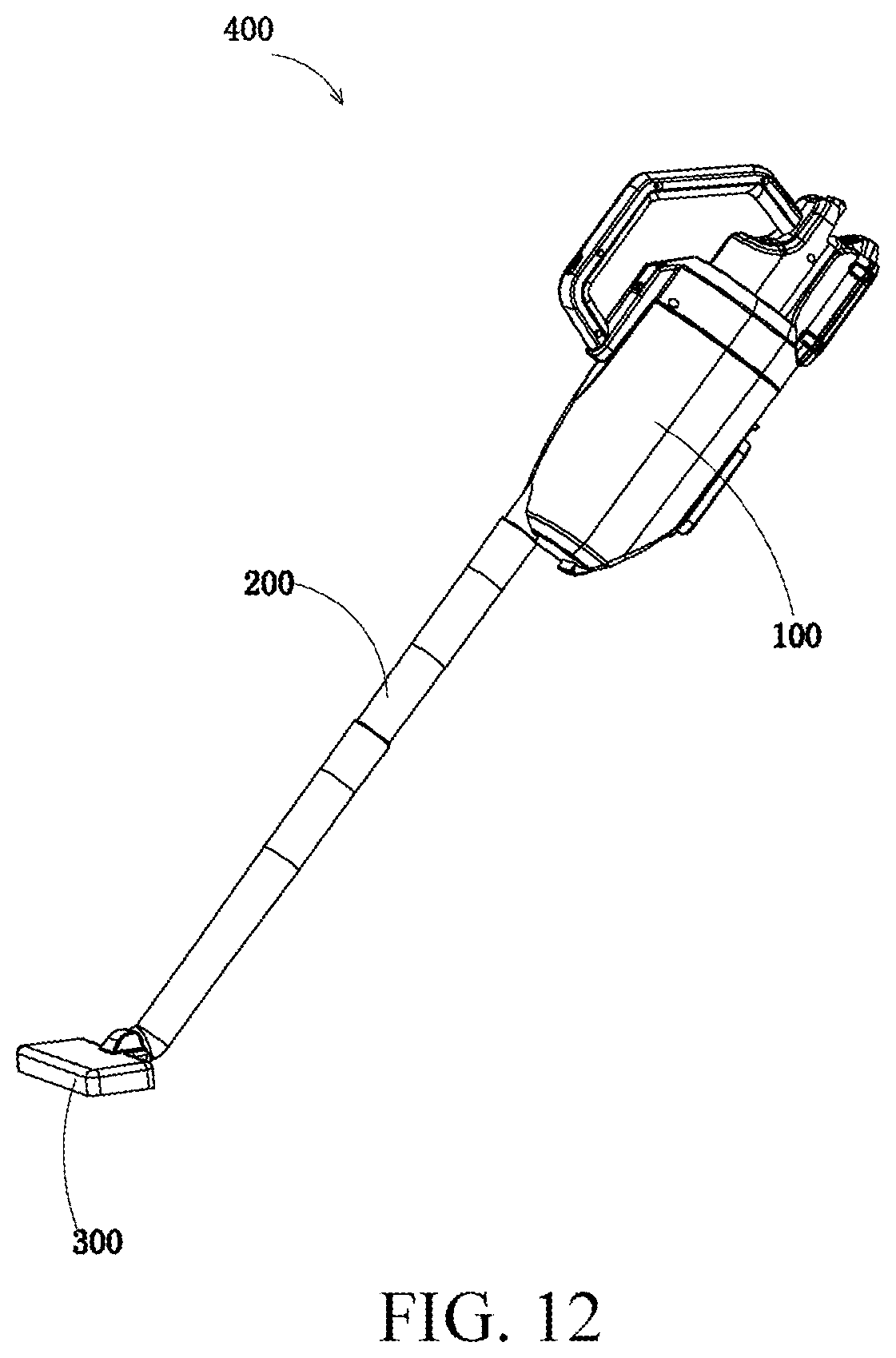
D00013
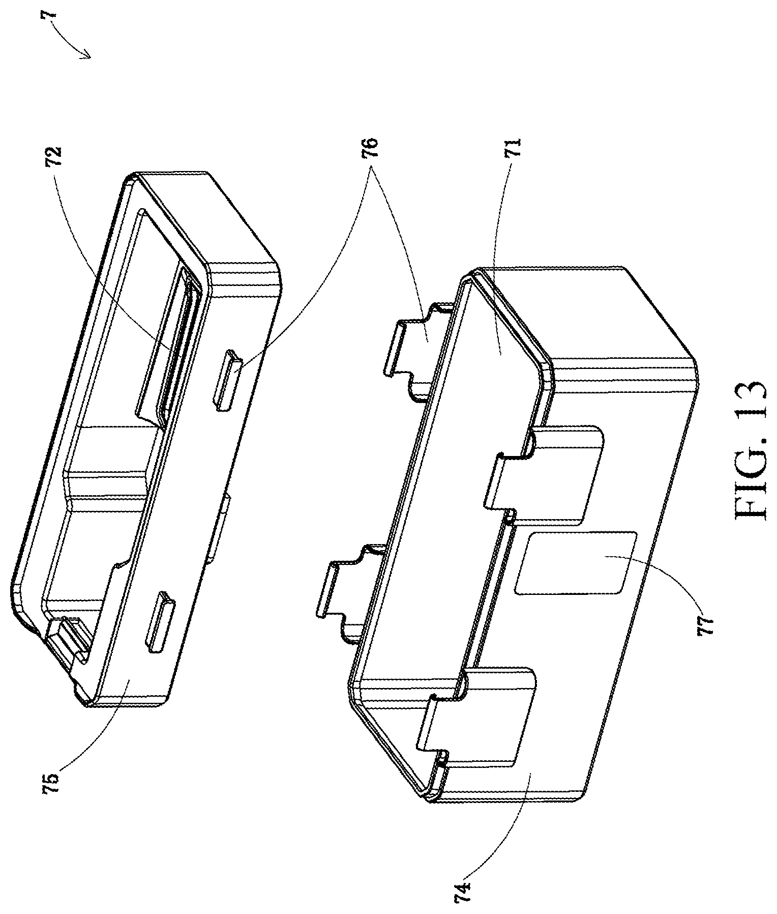
D00014

D00015
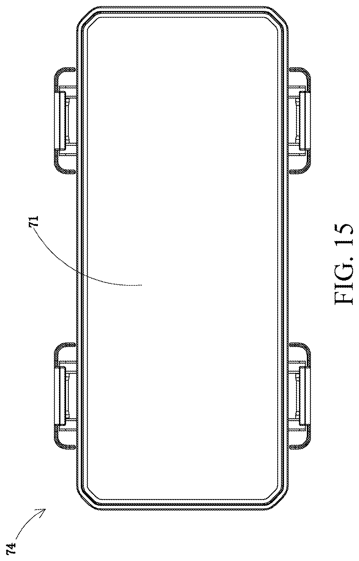
D00016
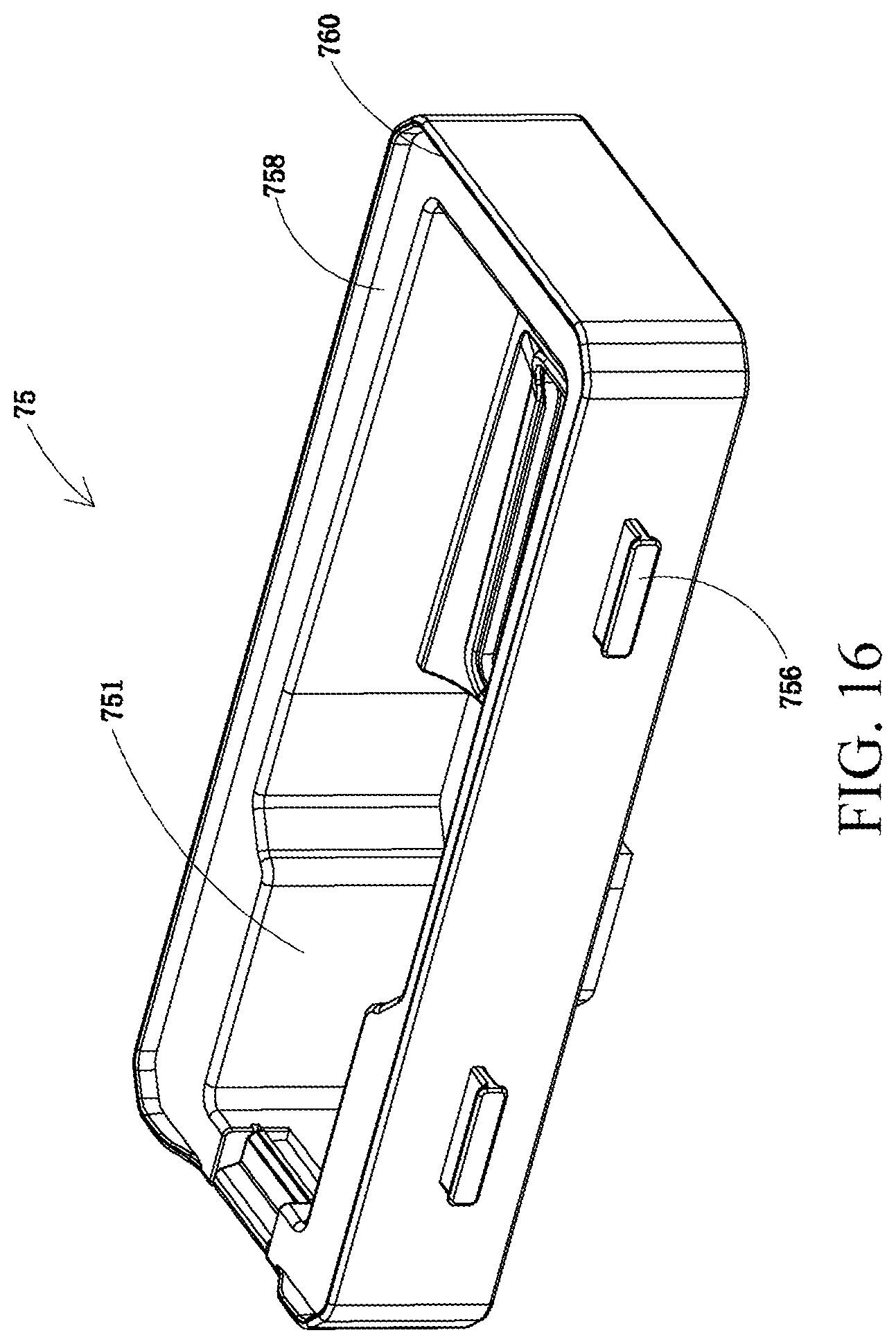
D00017
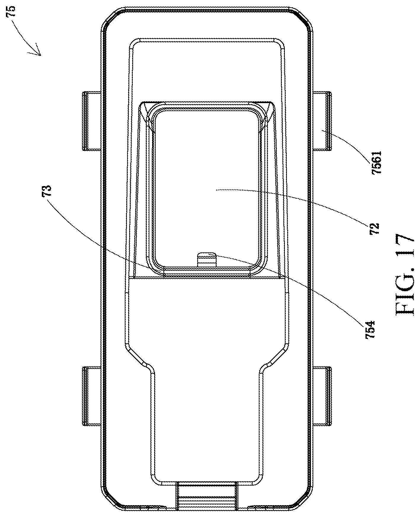
D00018
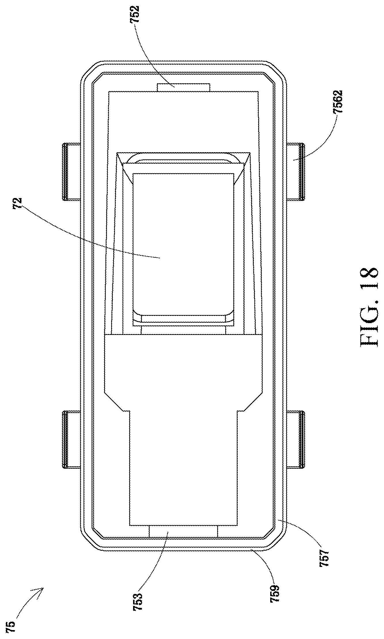
D00019
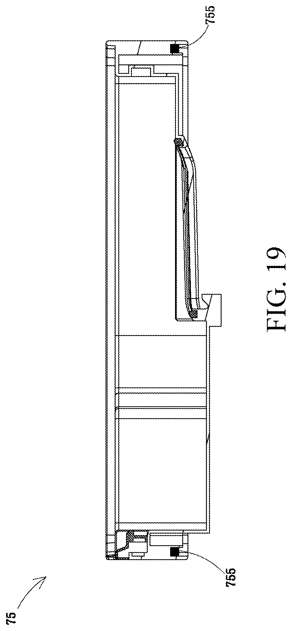
D00020
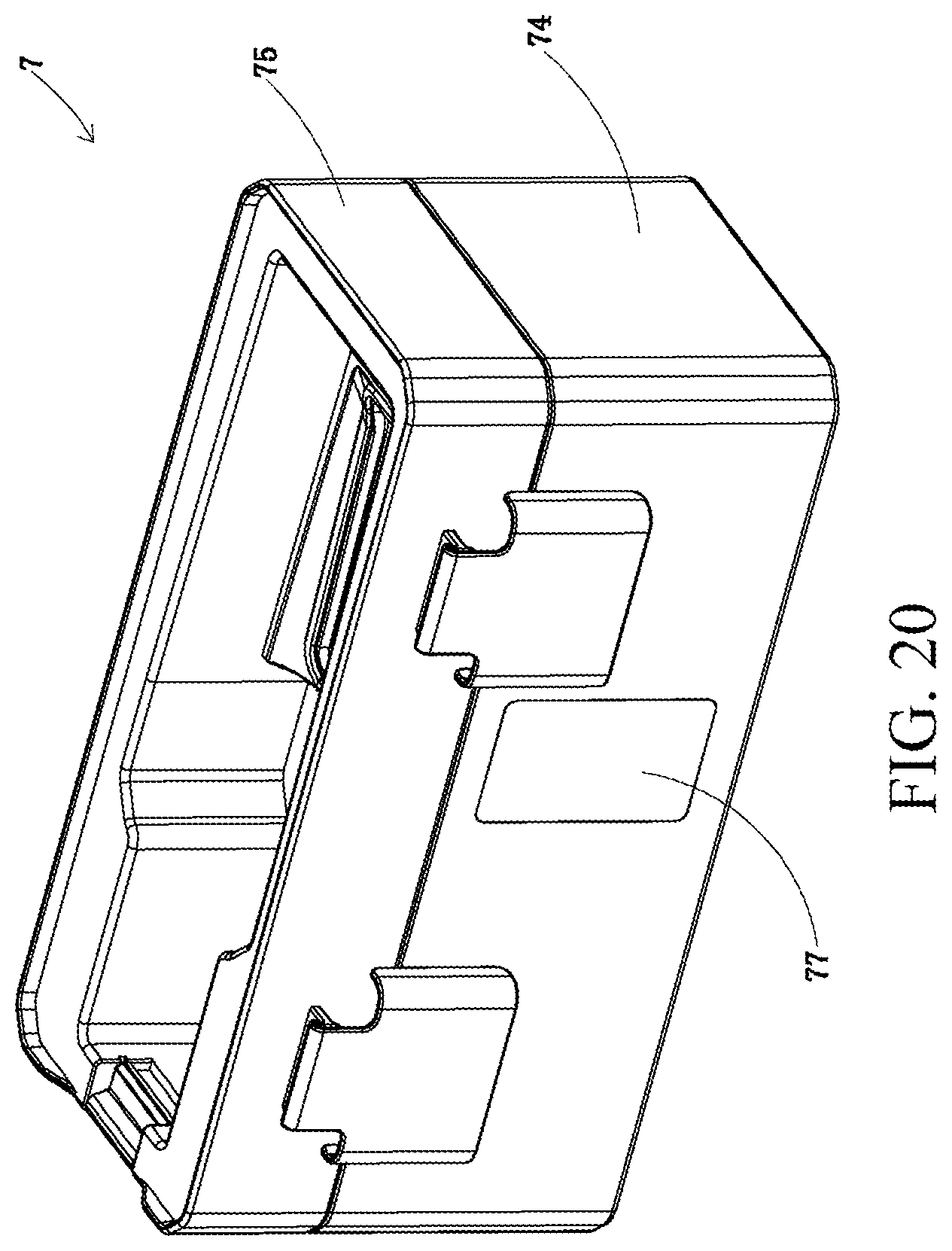
D00021
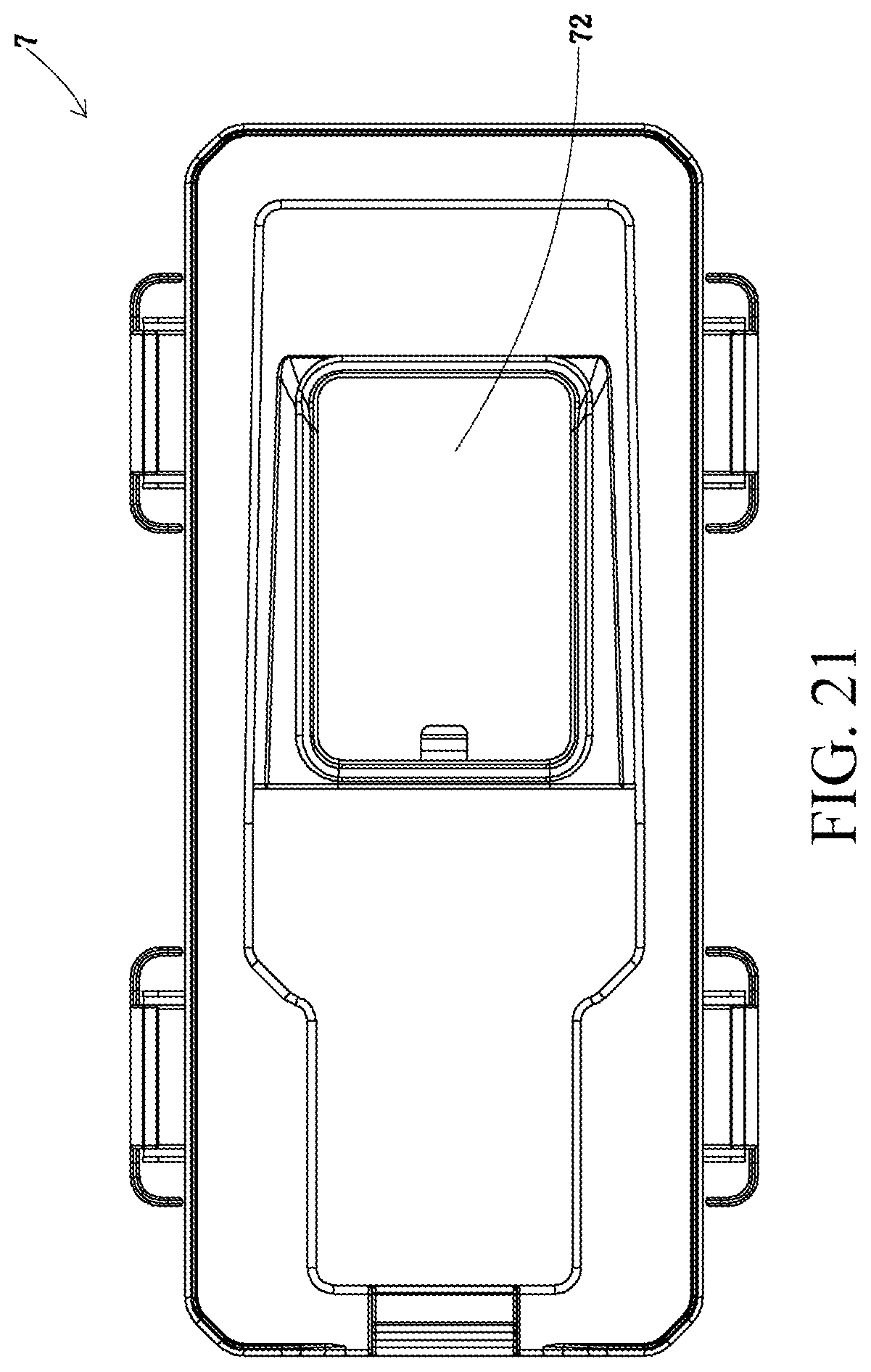
D00022
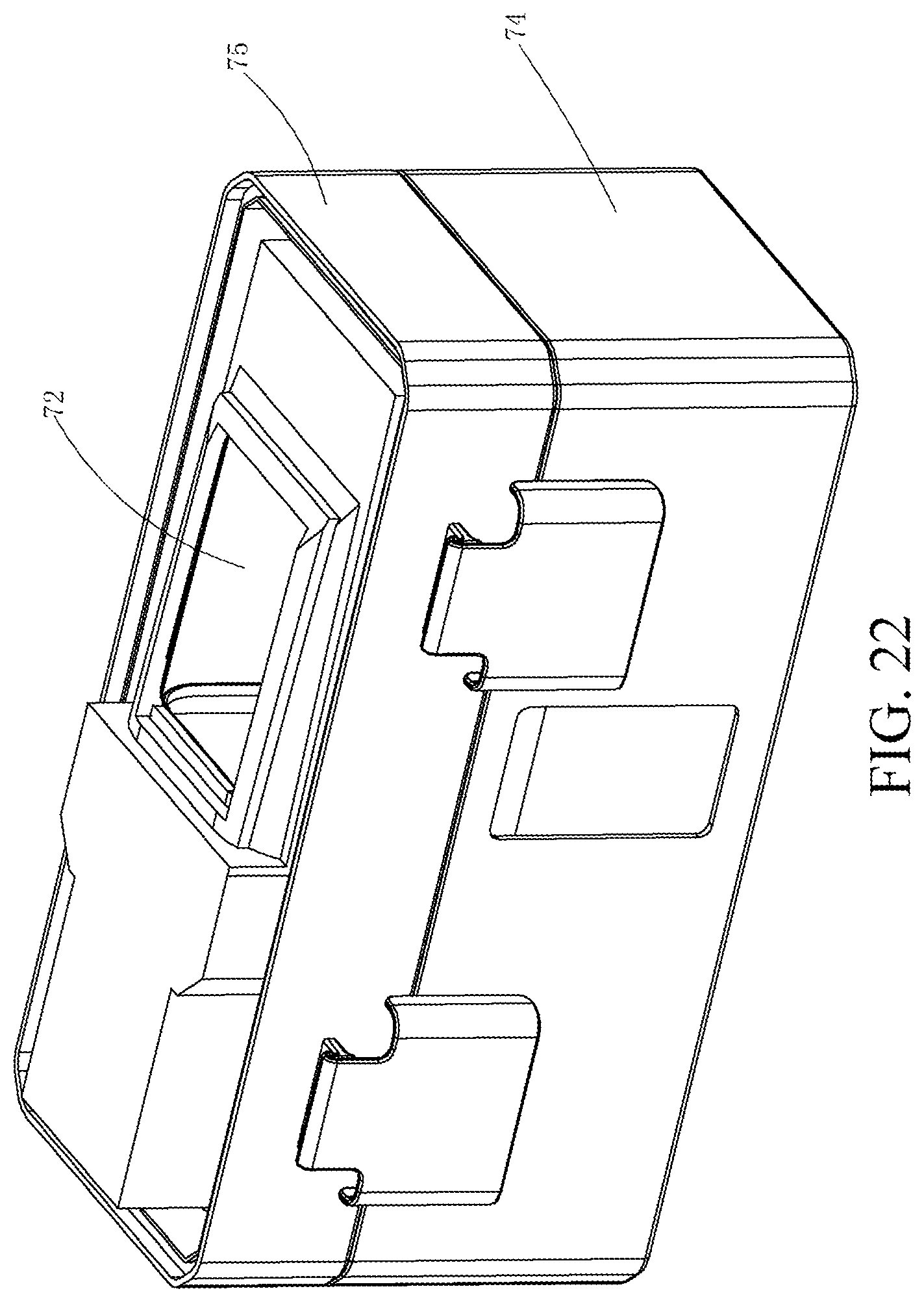
D00023
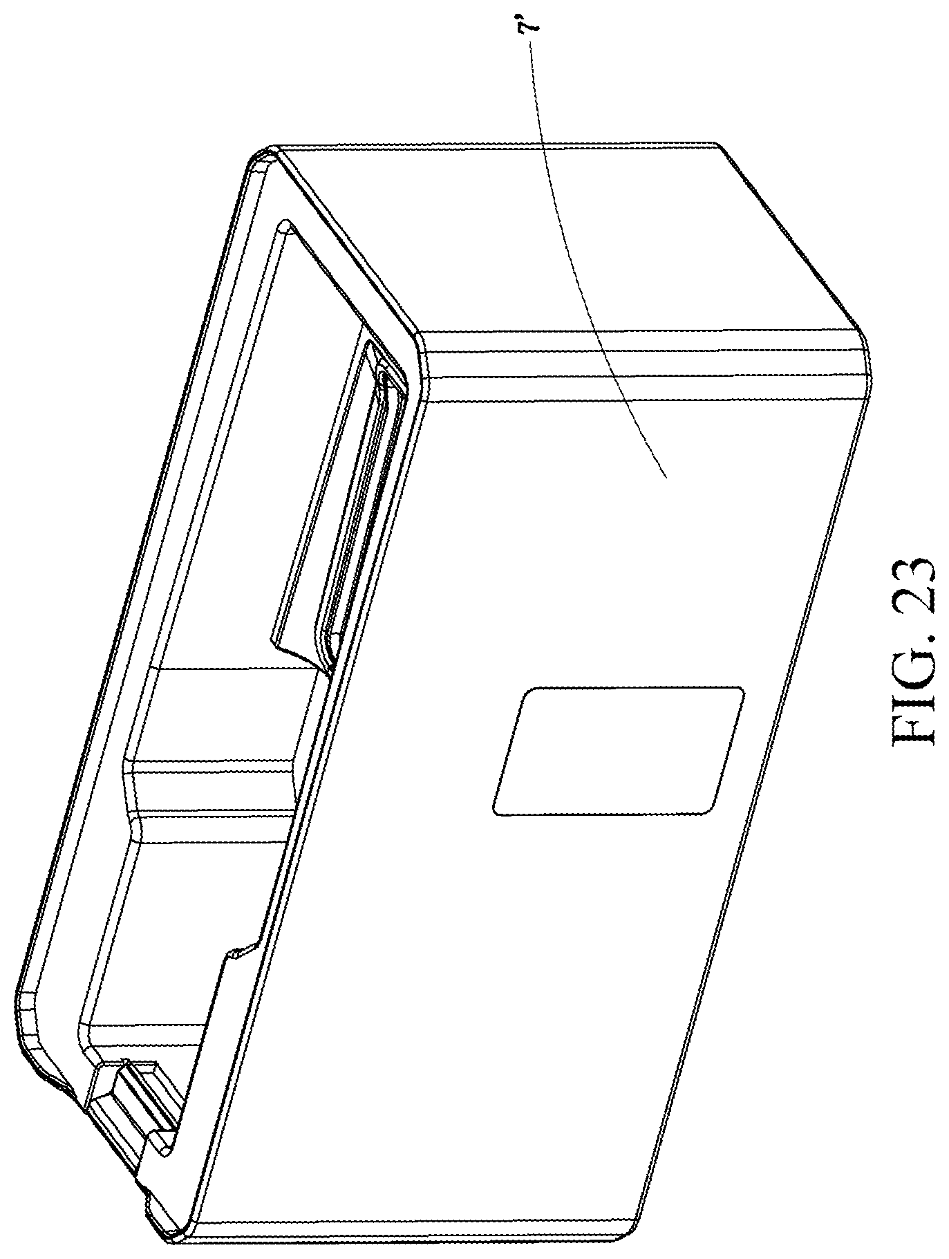
D00024
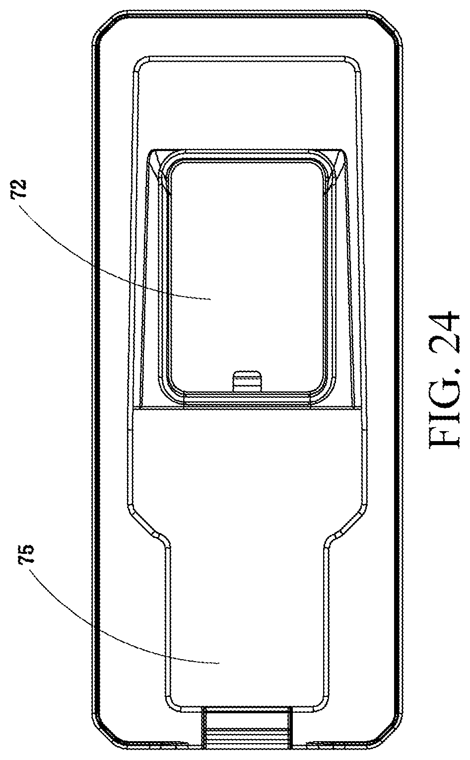
D00025

D00026
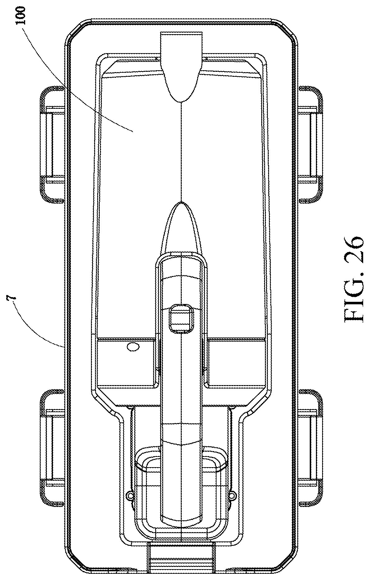
D00027
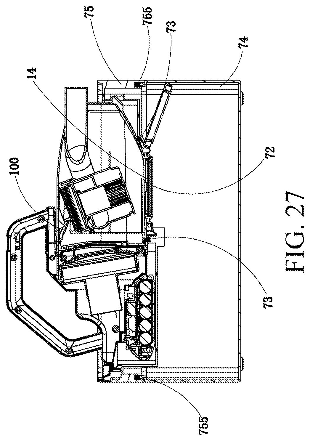
D00028

D00029
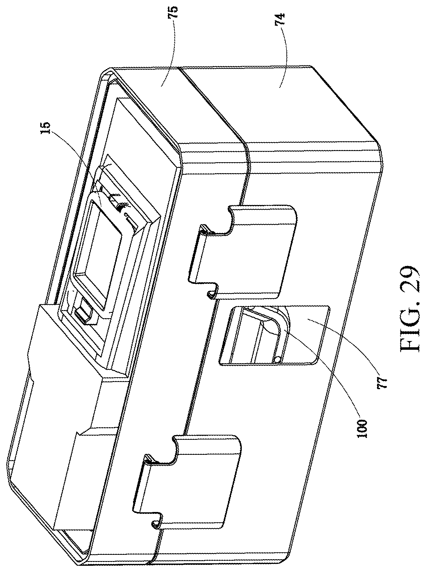
D00030

D00031
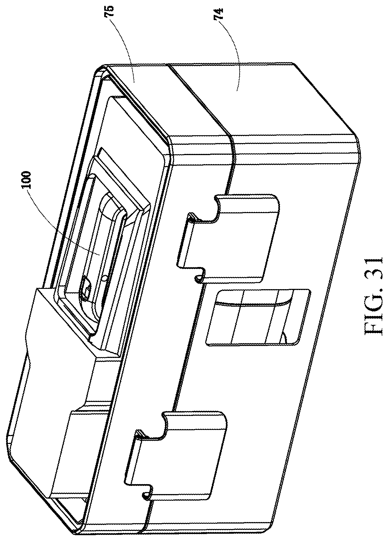
D00032
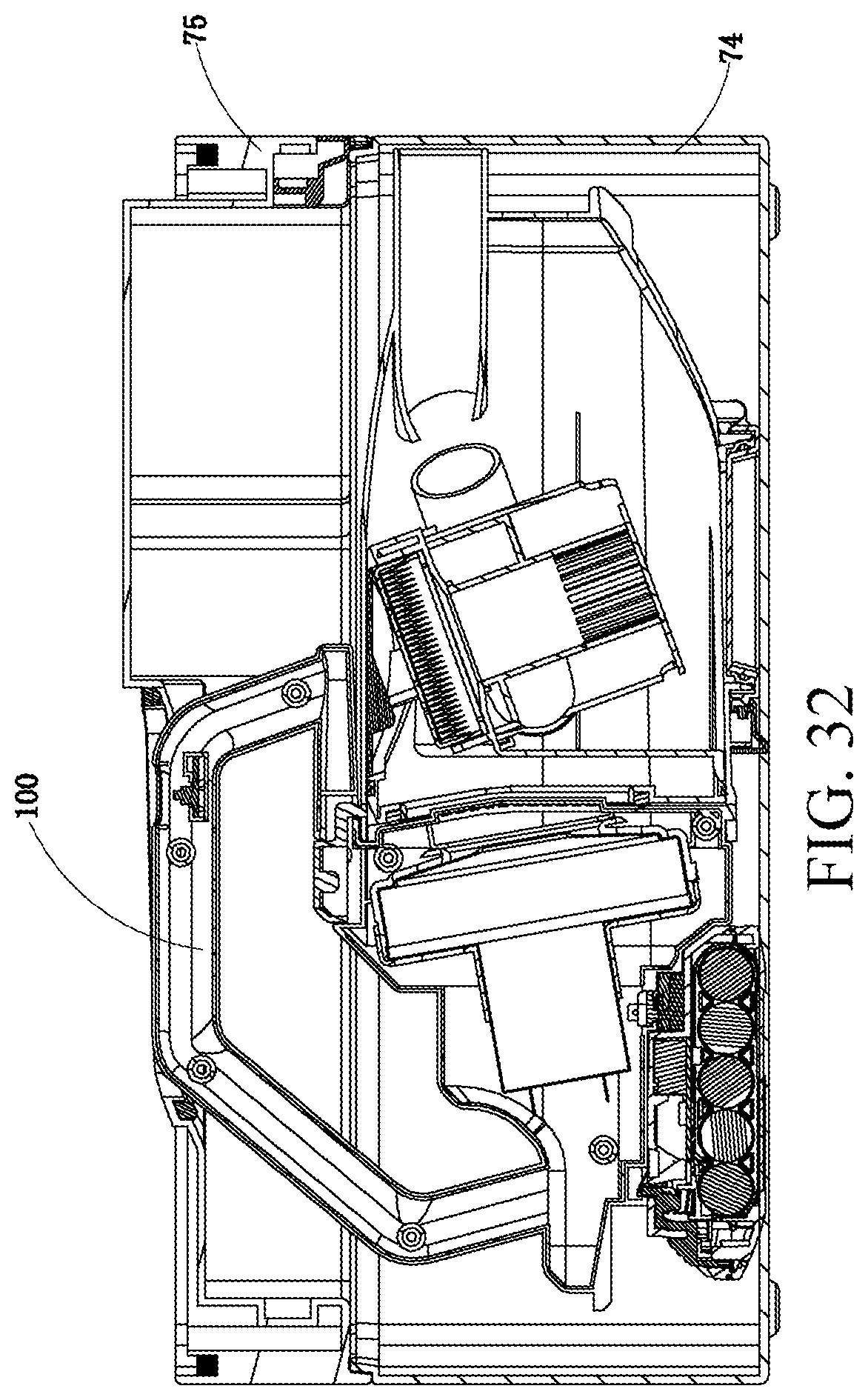
D00033
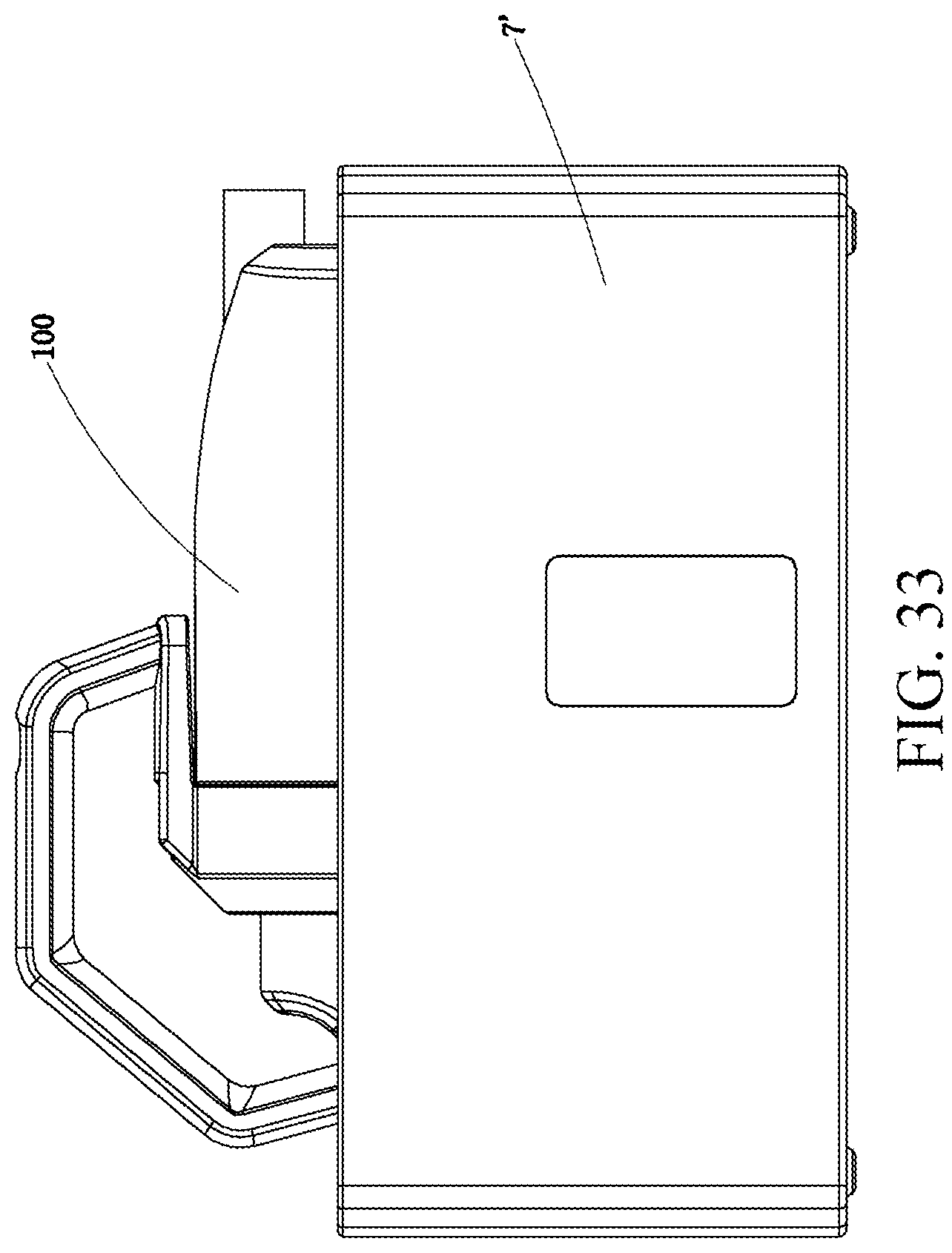
D00034
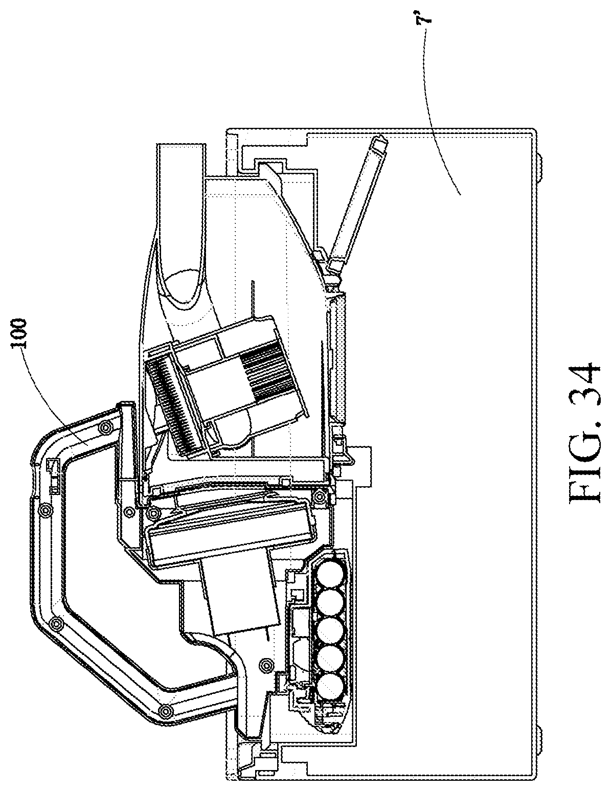
D00035
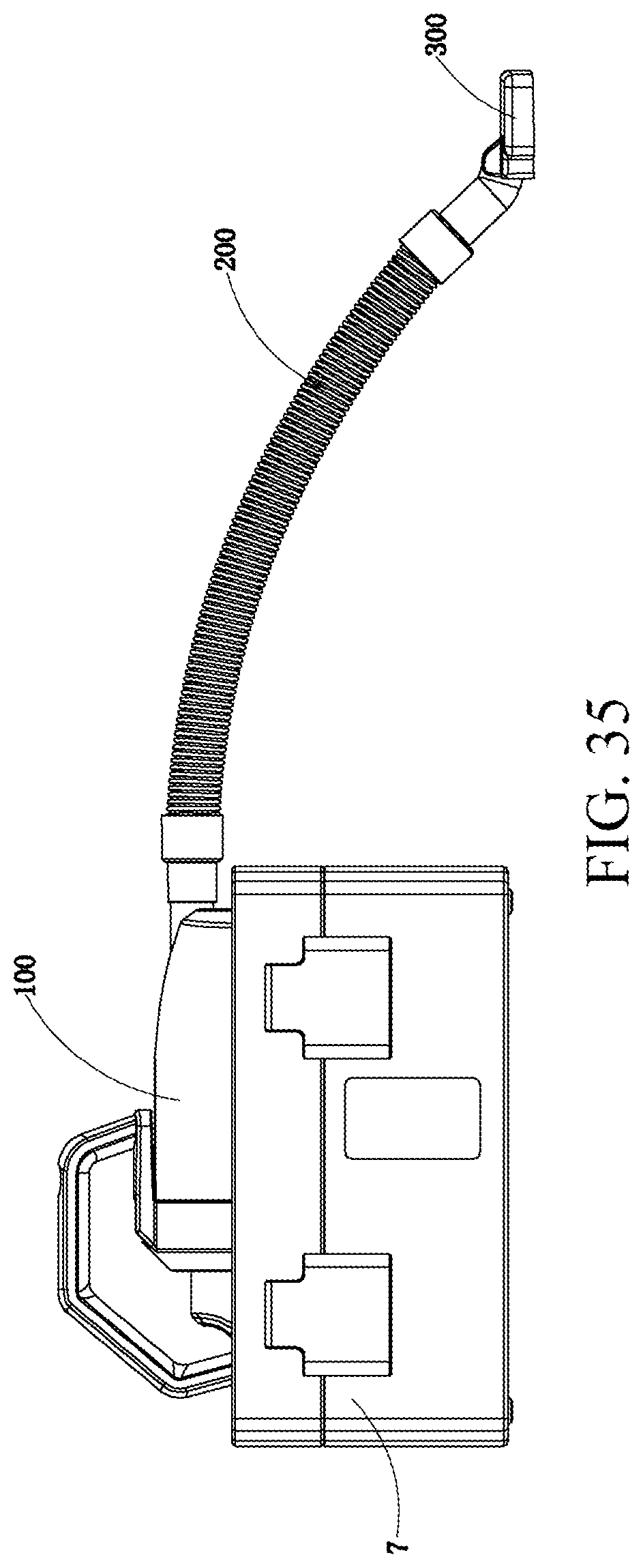
D00036
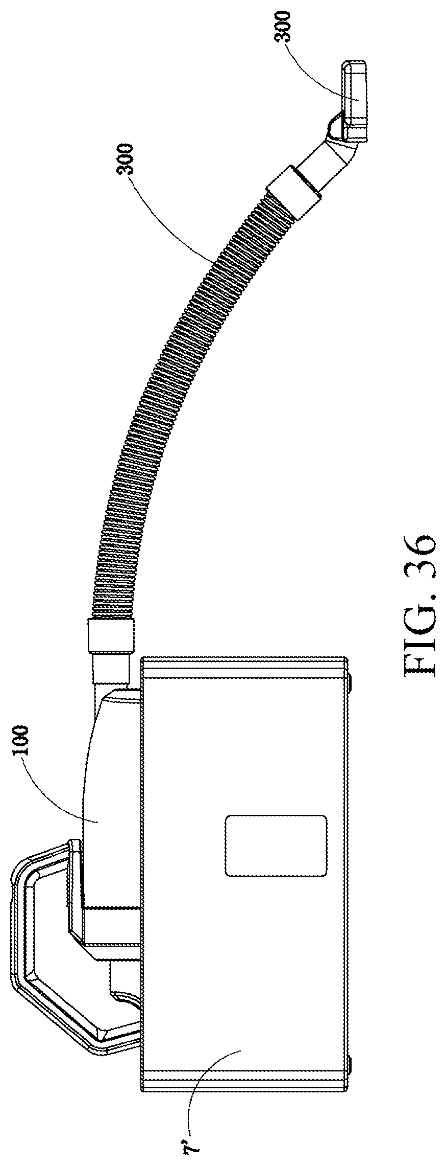
D00037
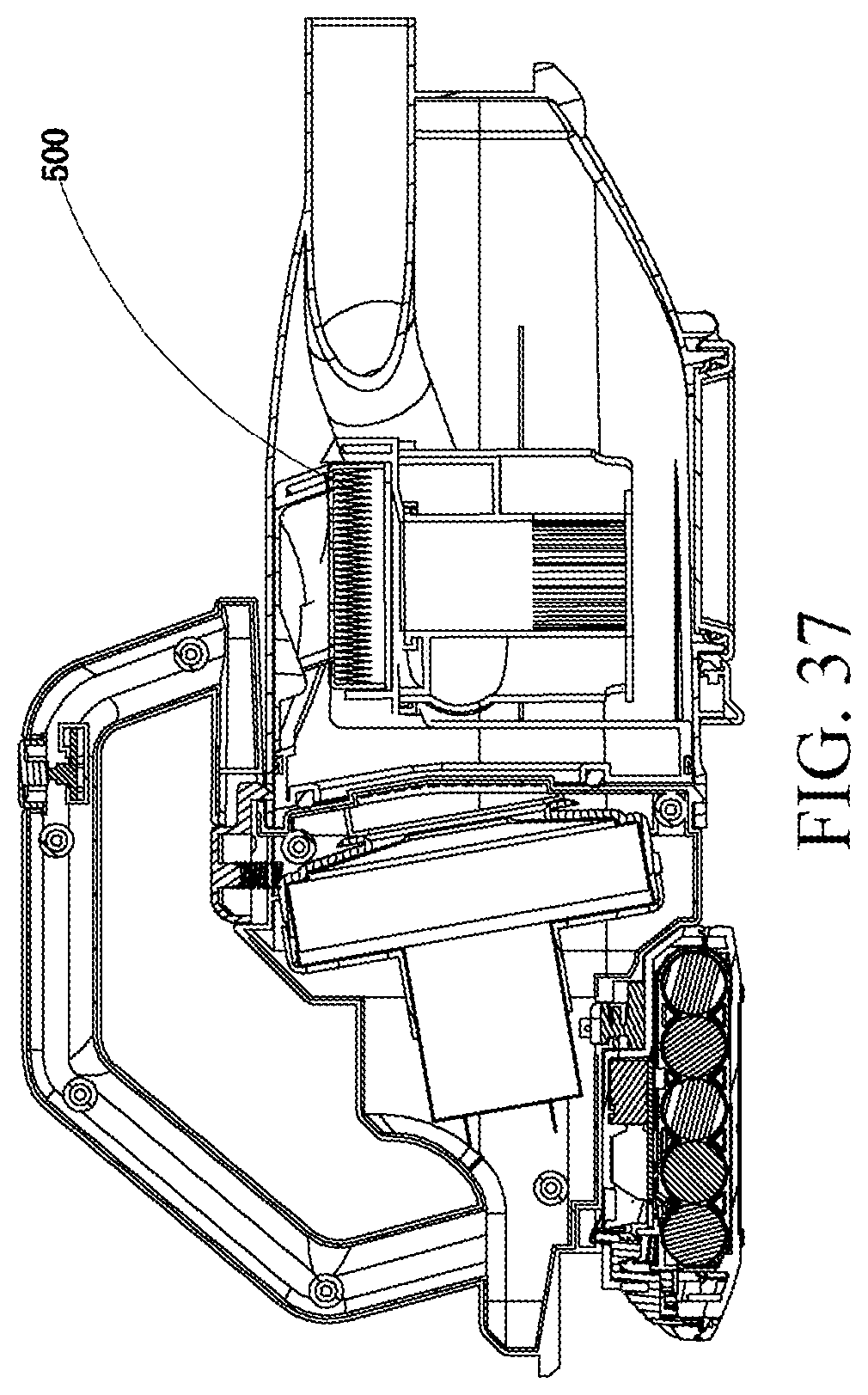
D00038
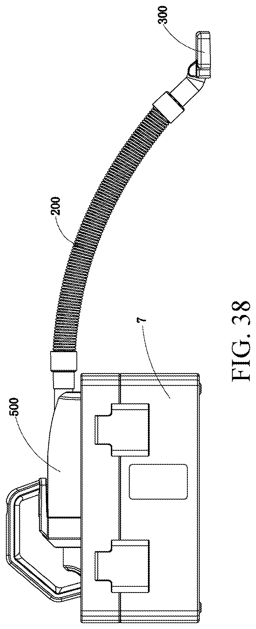
D00039
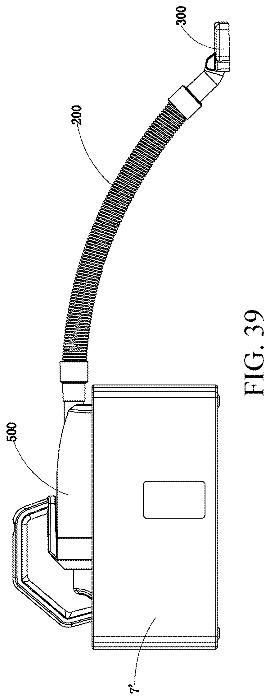
D00040
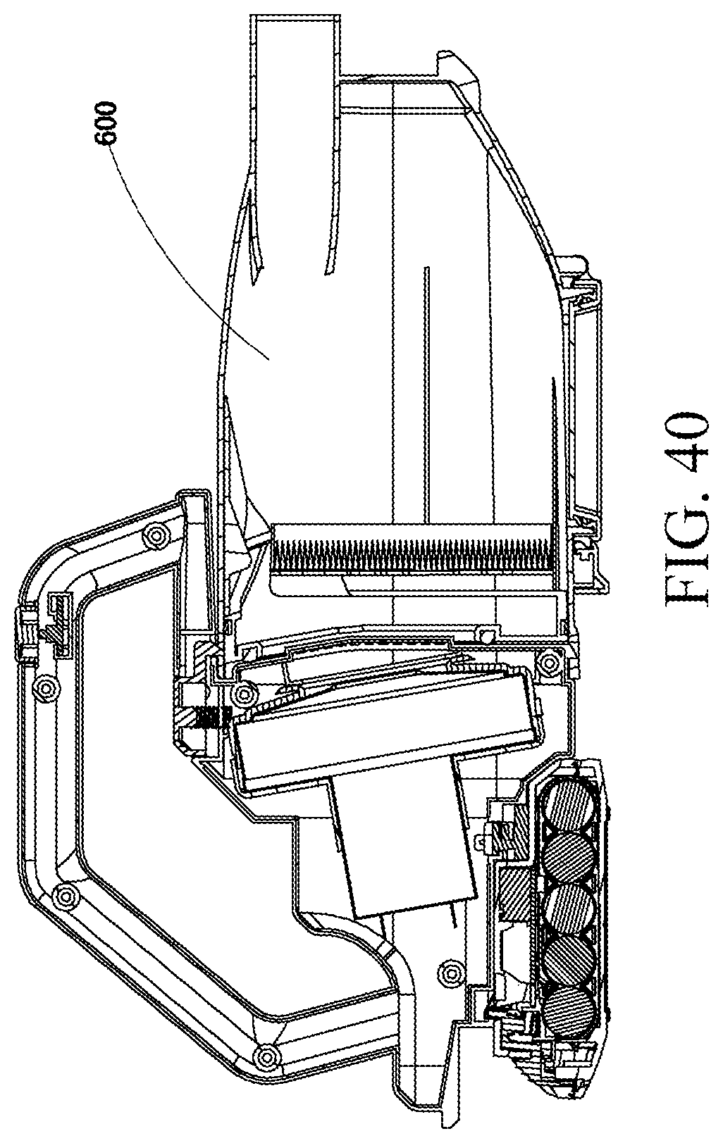
D00041

D00042
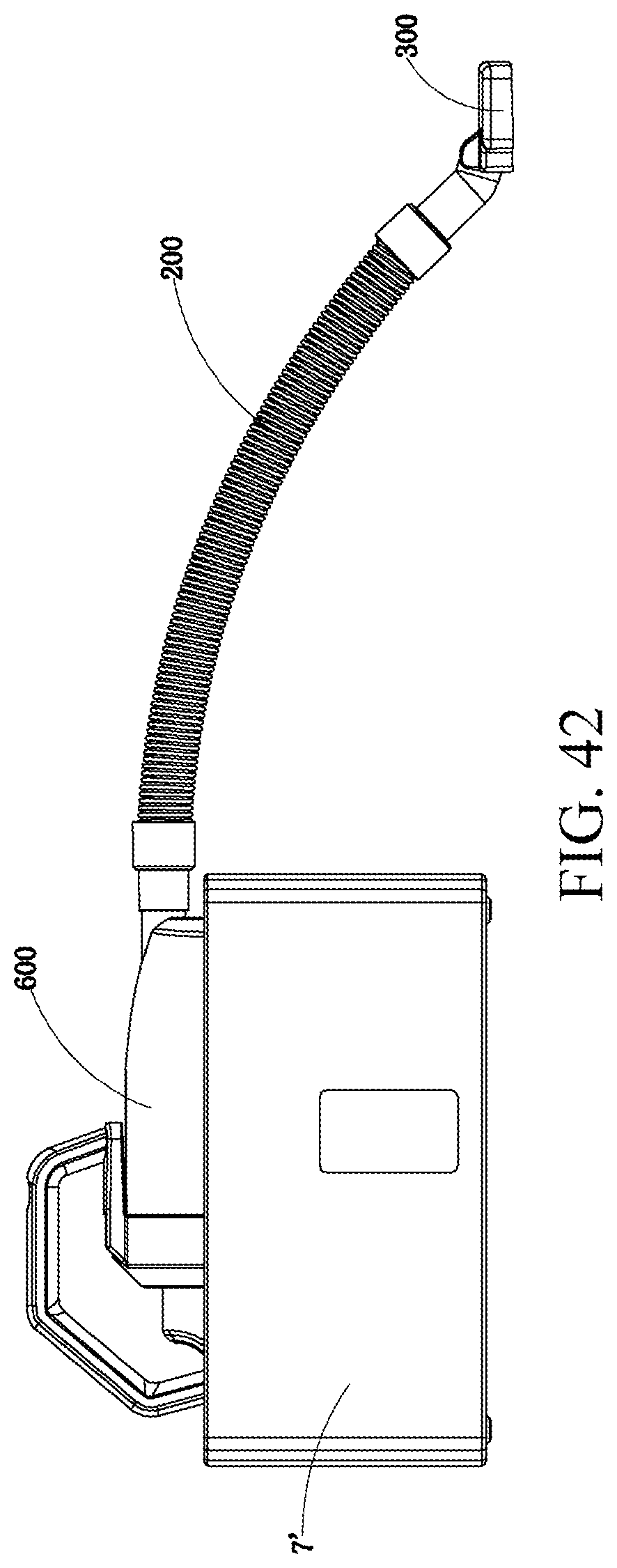
D00043
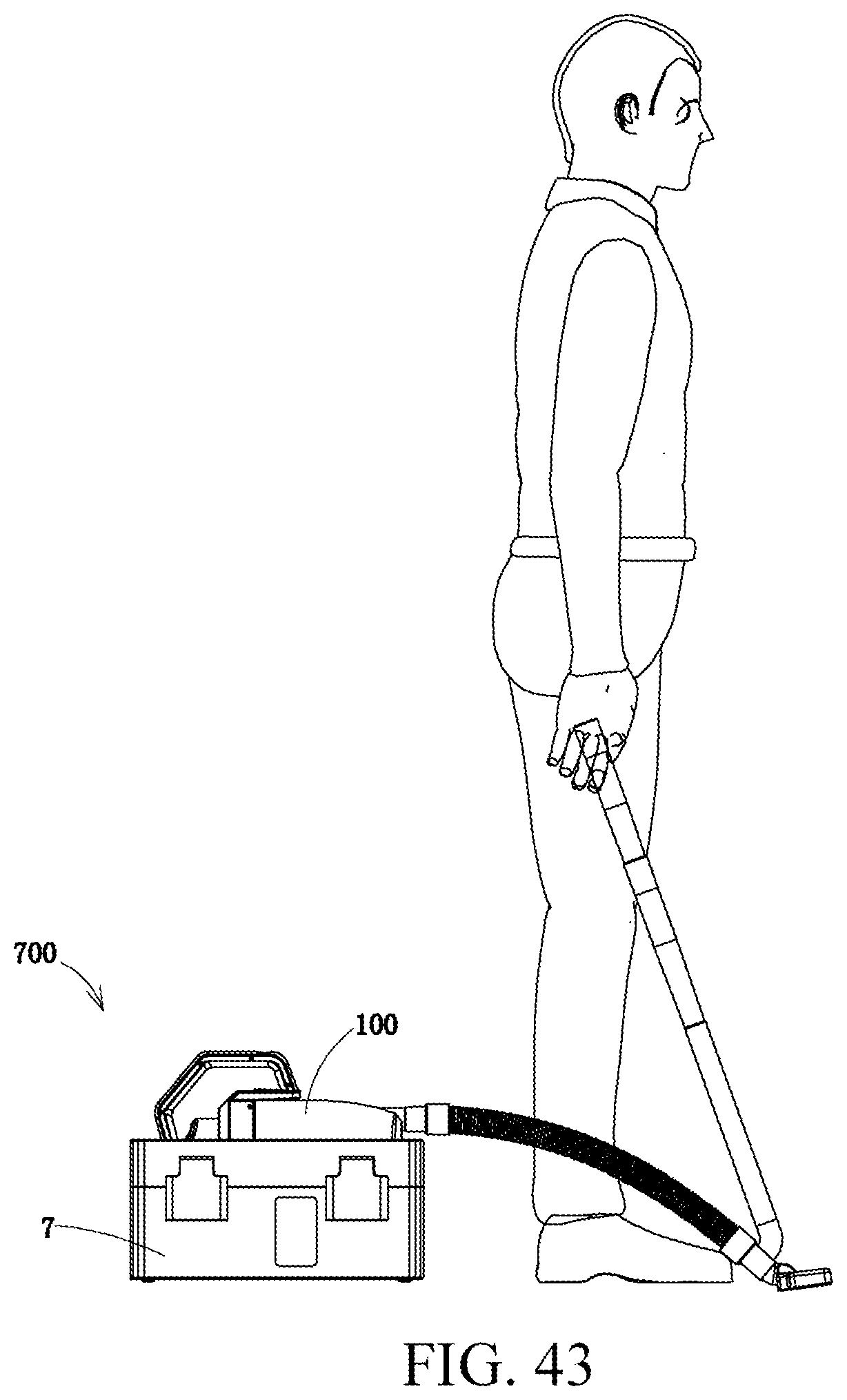
D00044

D00045
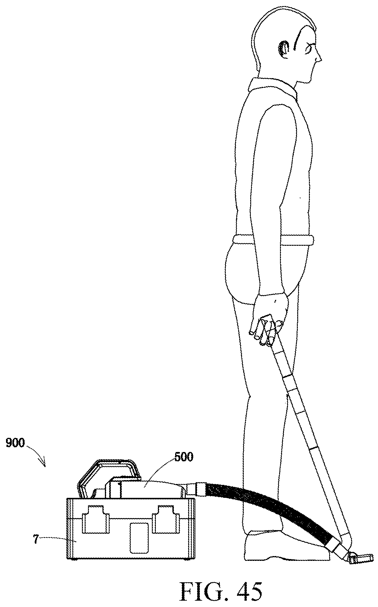
D00046
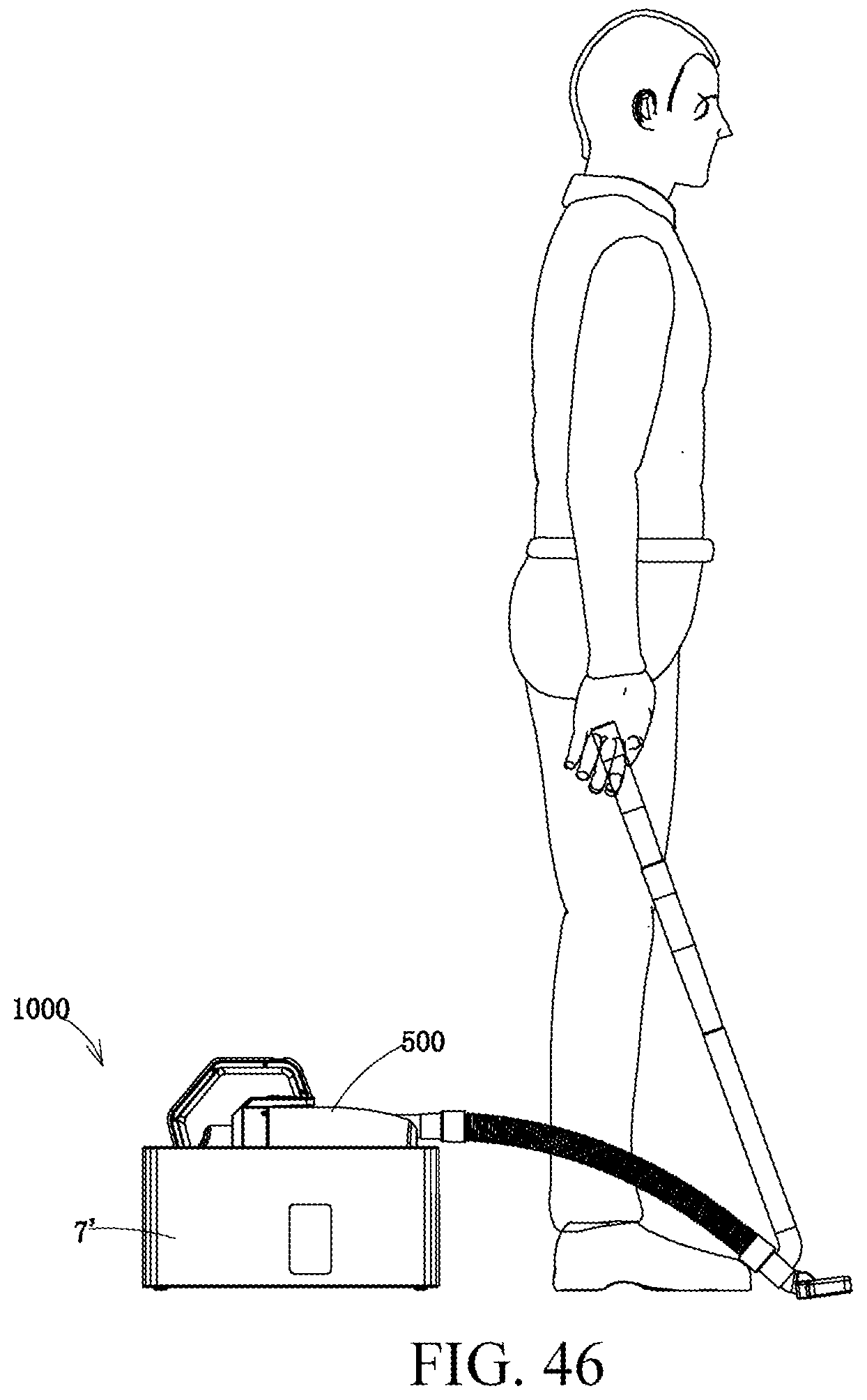
D00047

D00048
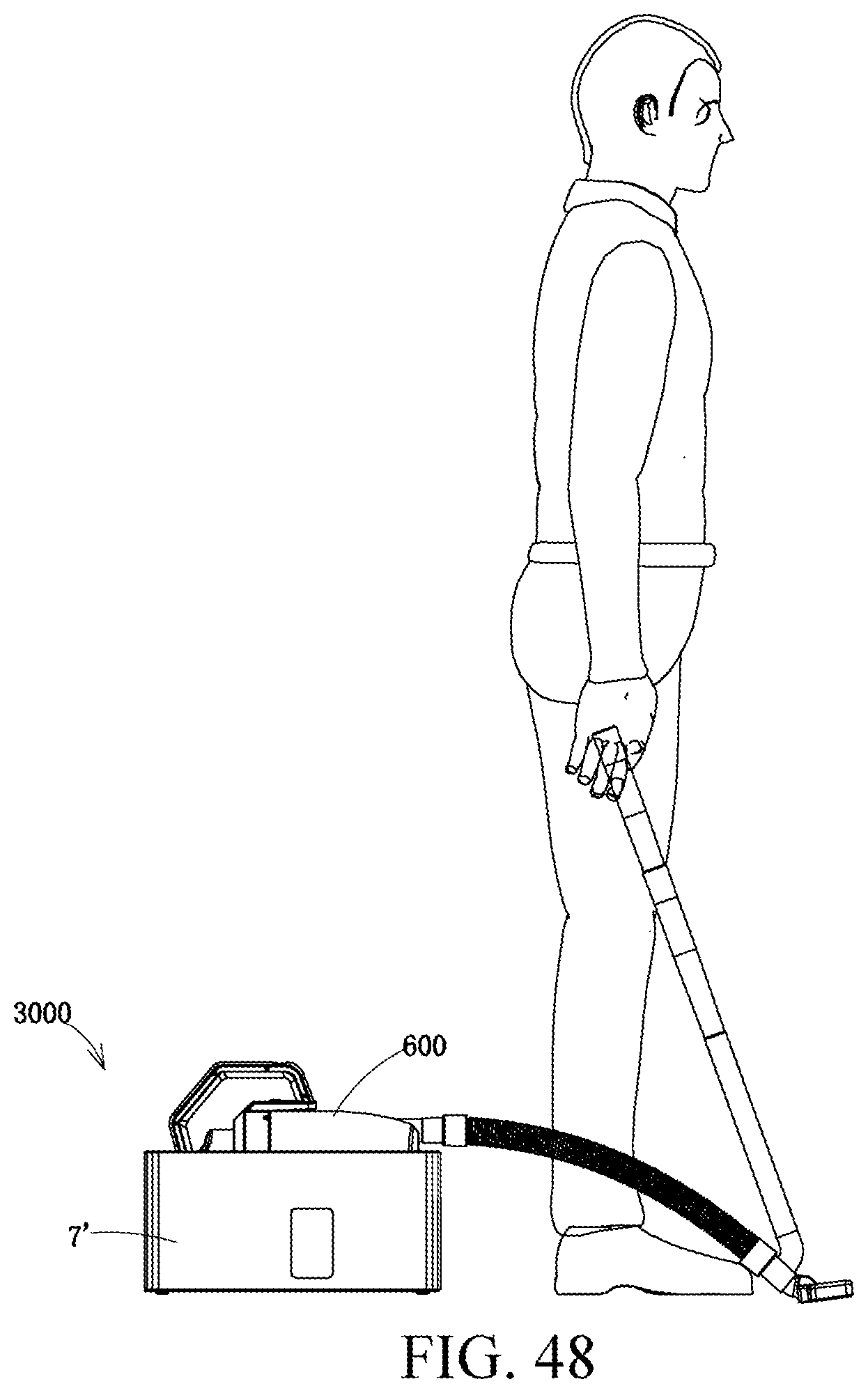
D00049
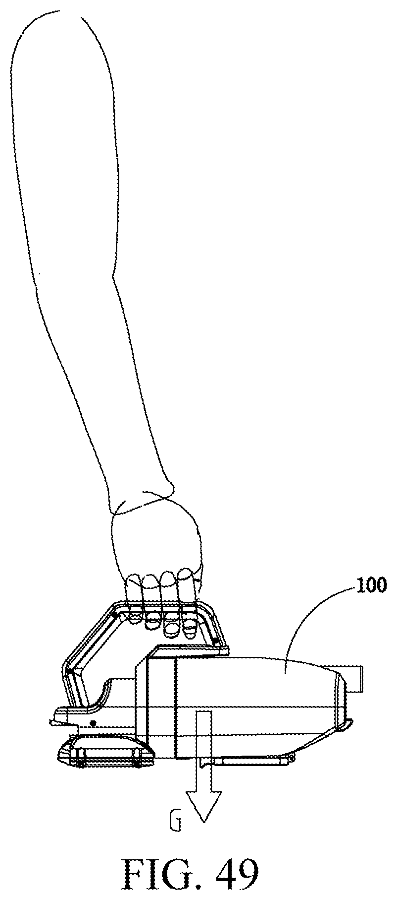
D00050
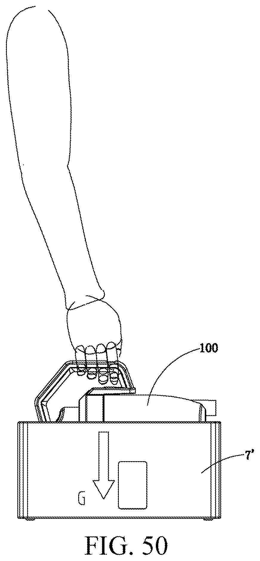
D00051
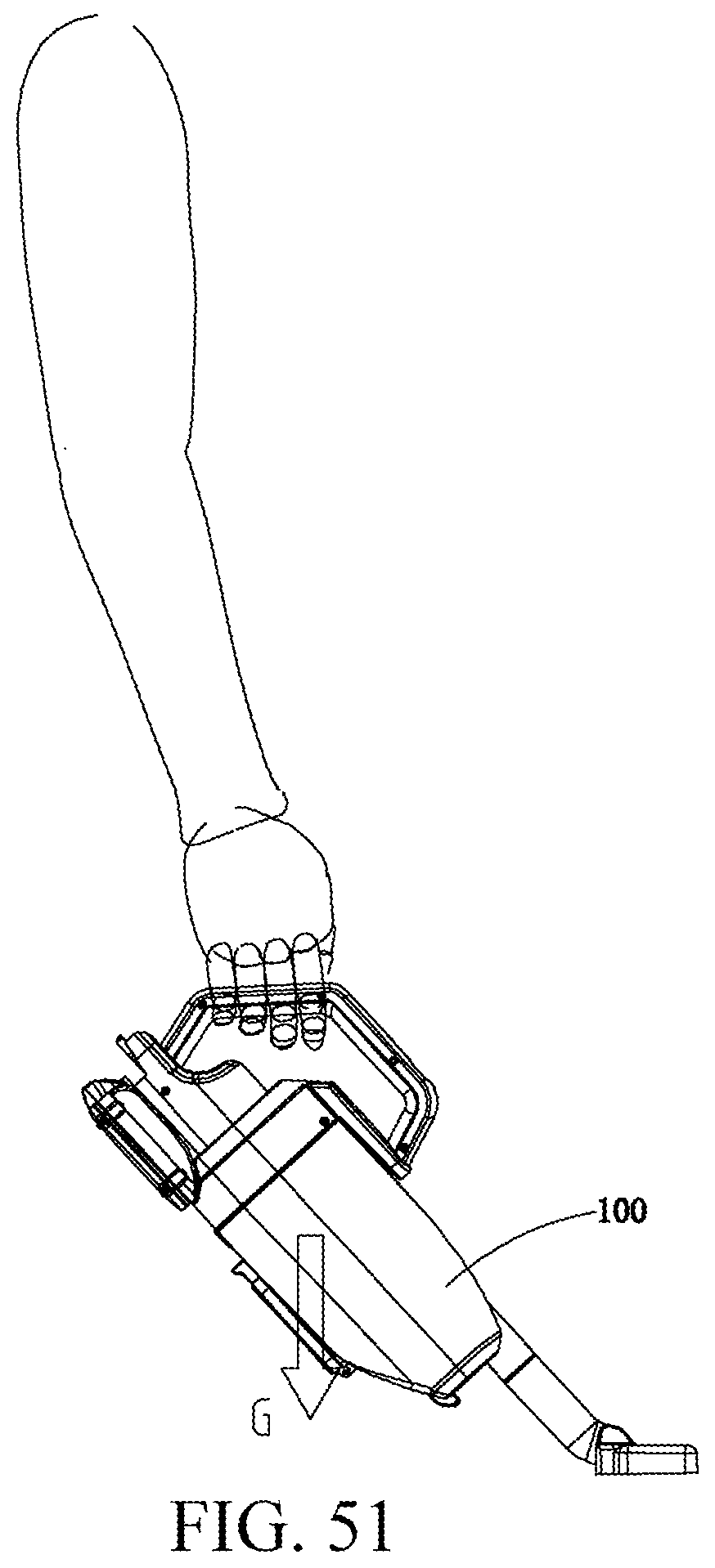
D00052
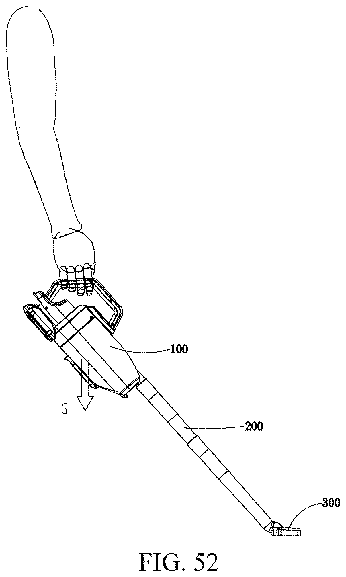
D00053
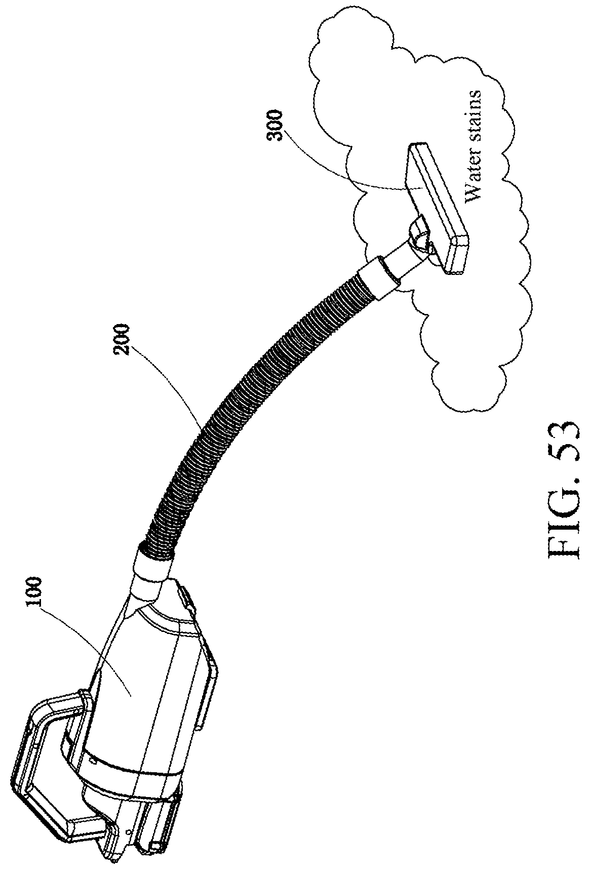
D00054
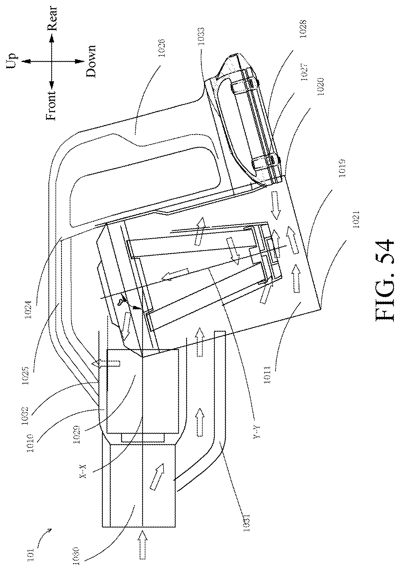
D00055
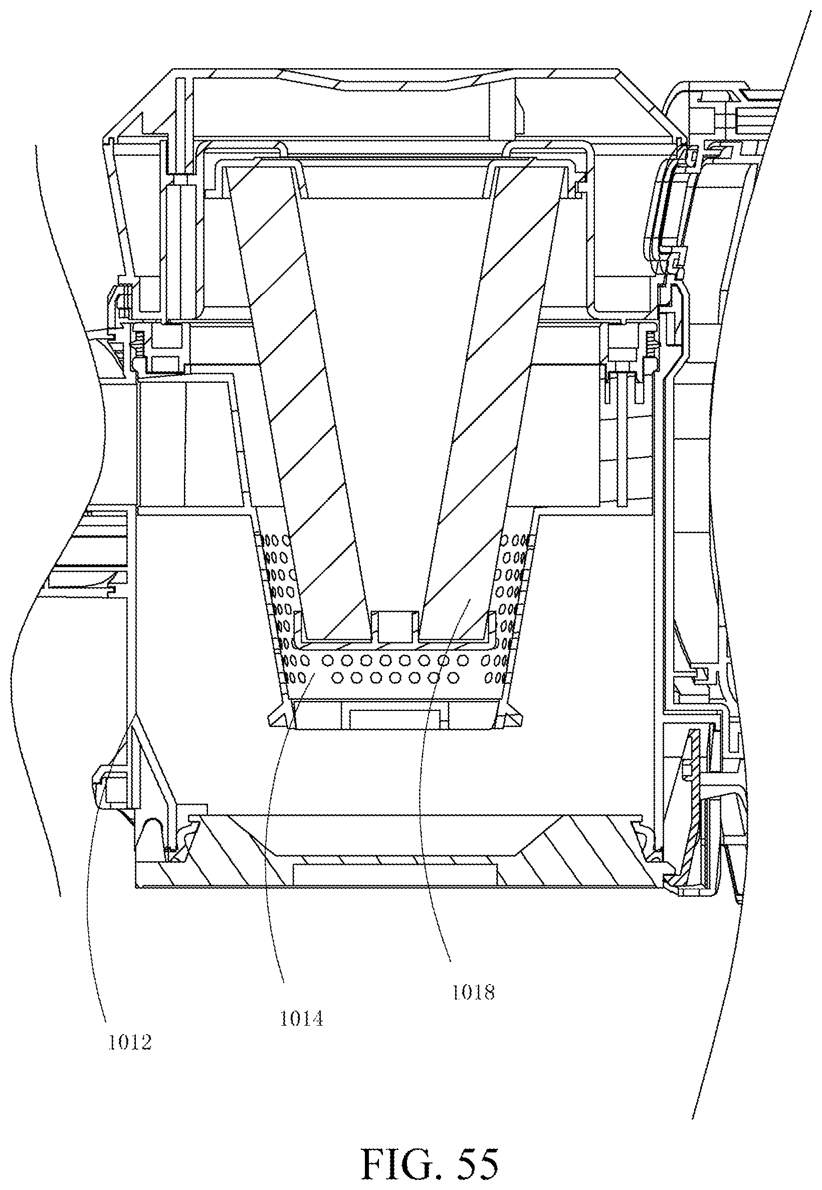
D00056
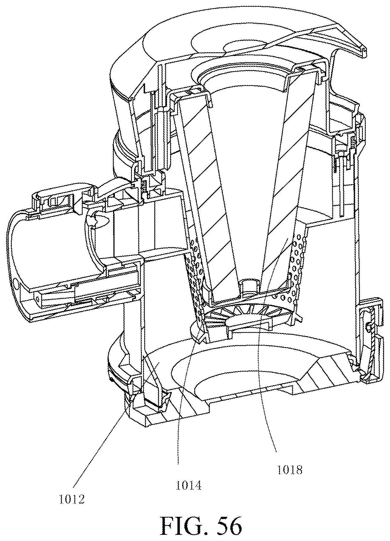
D00057
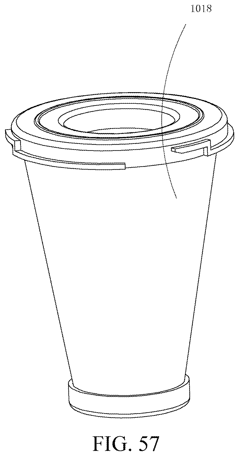
D00058
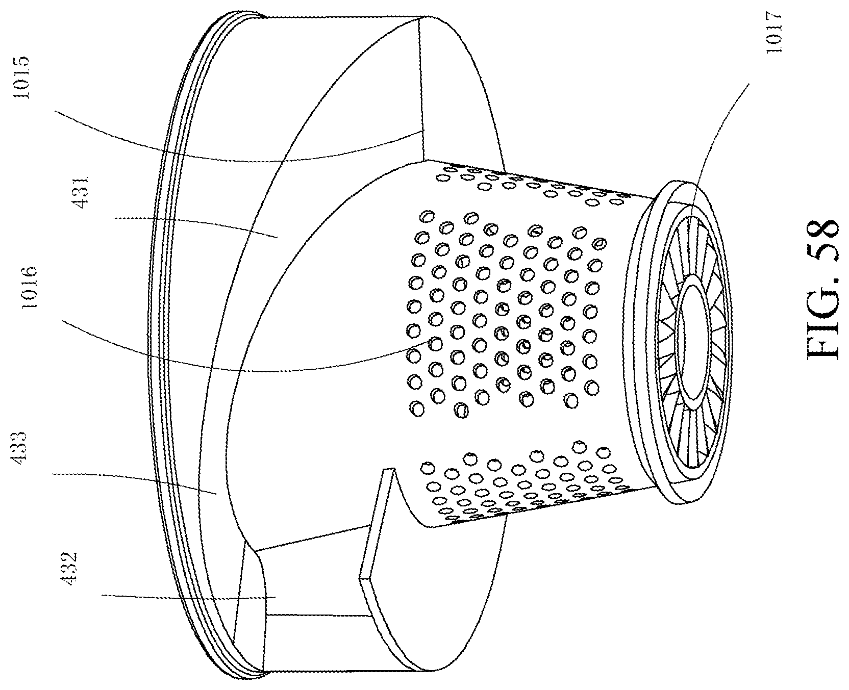
D00059
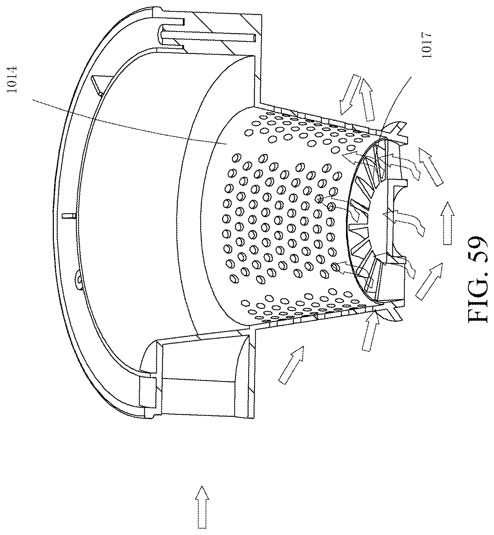
D00060
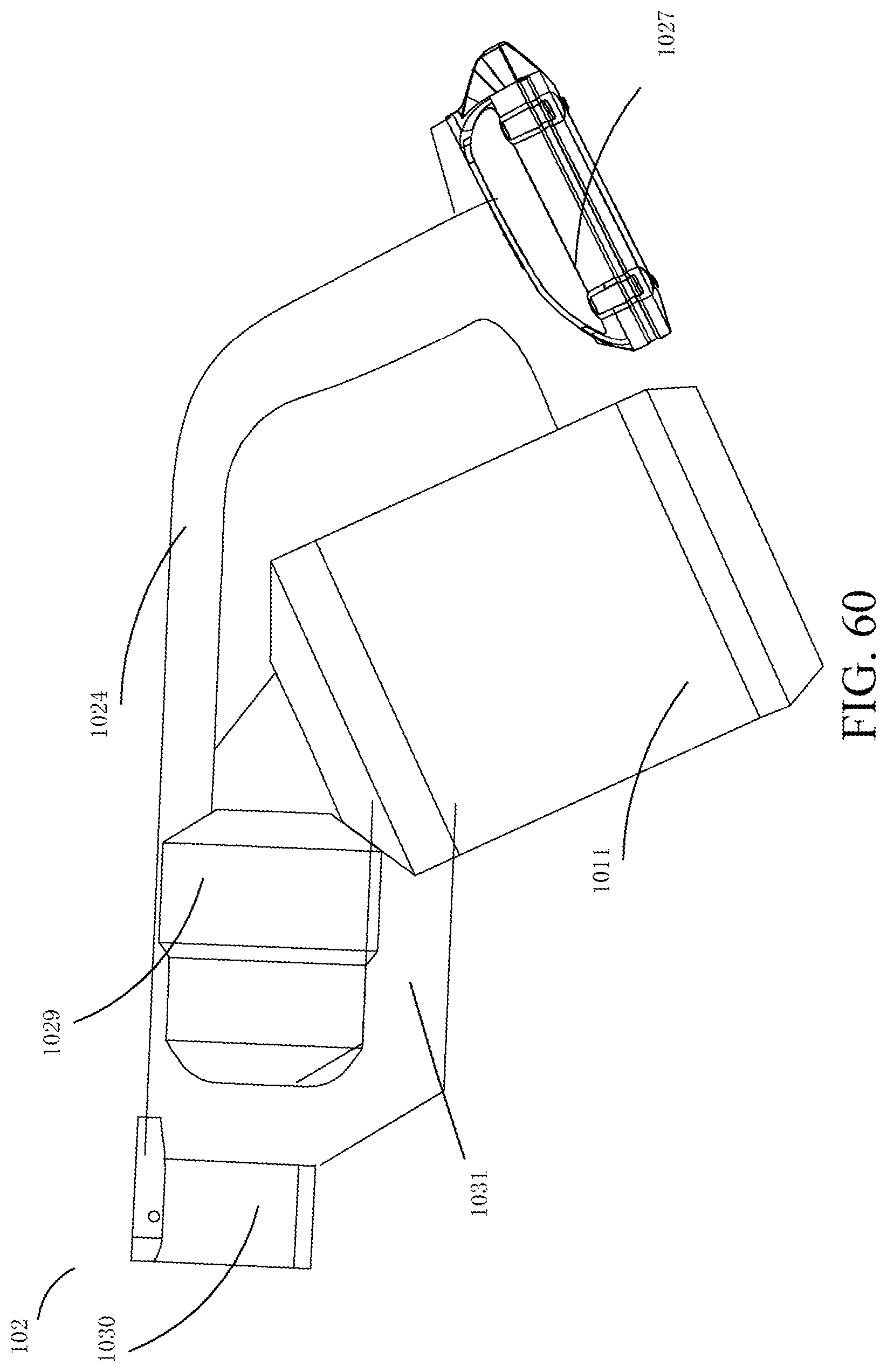
D00061
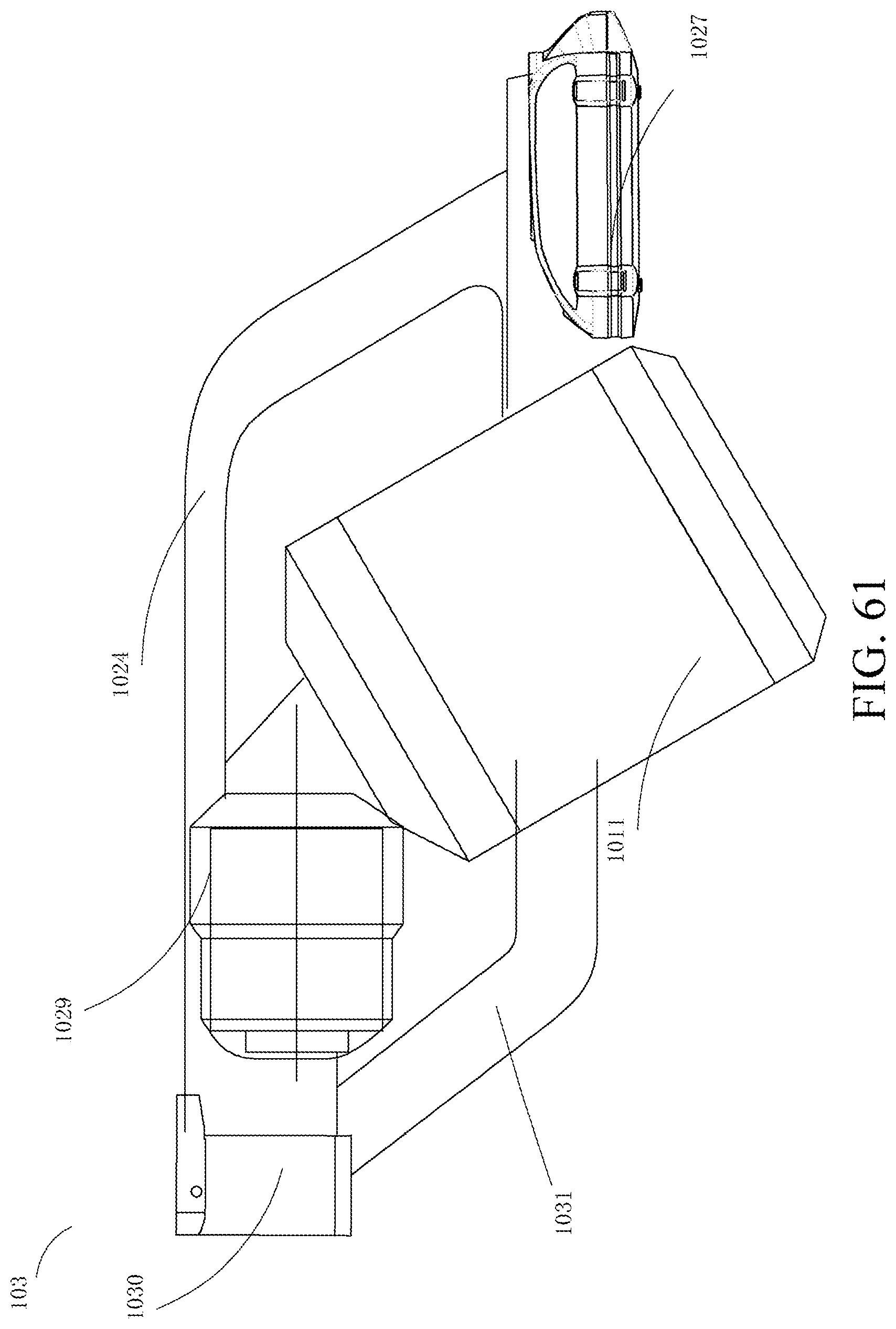
D00062
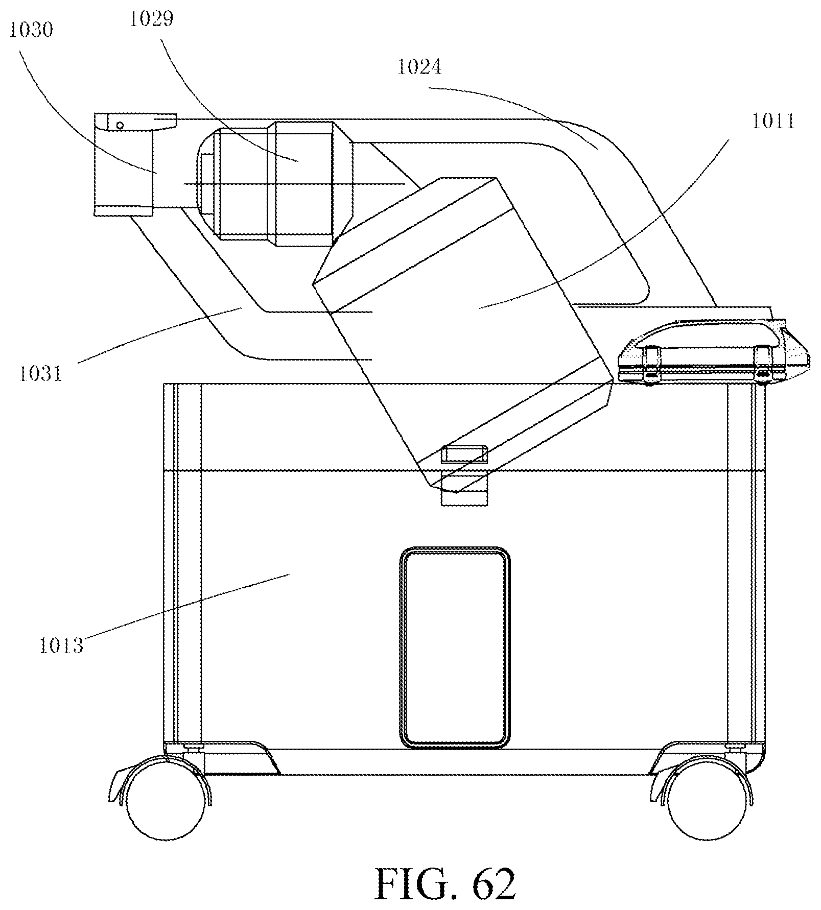
D00063
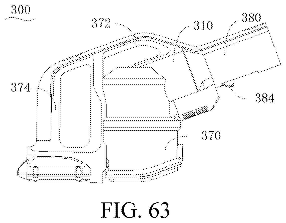
D00064
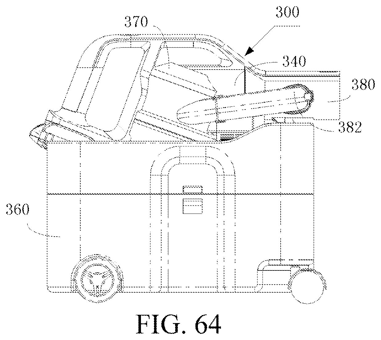
D00065
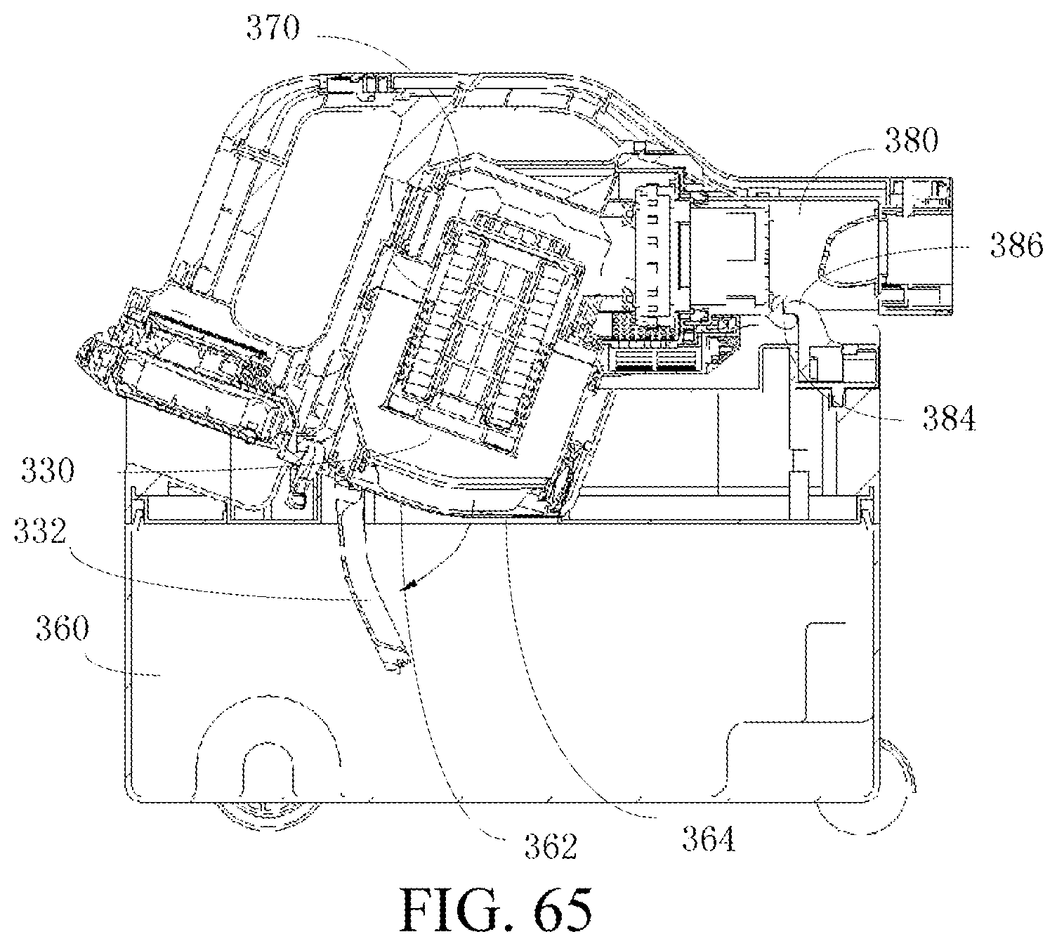
D00066
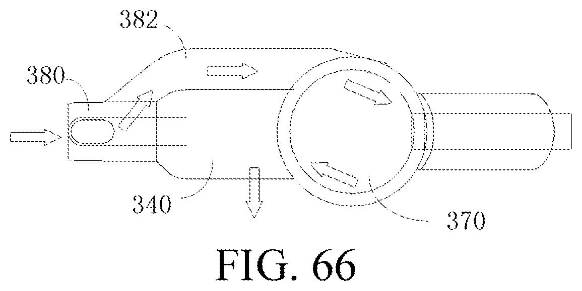
D00067
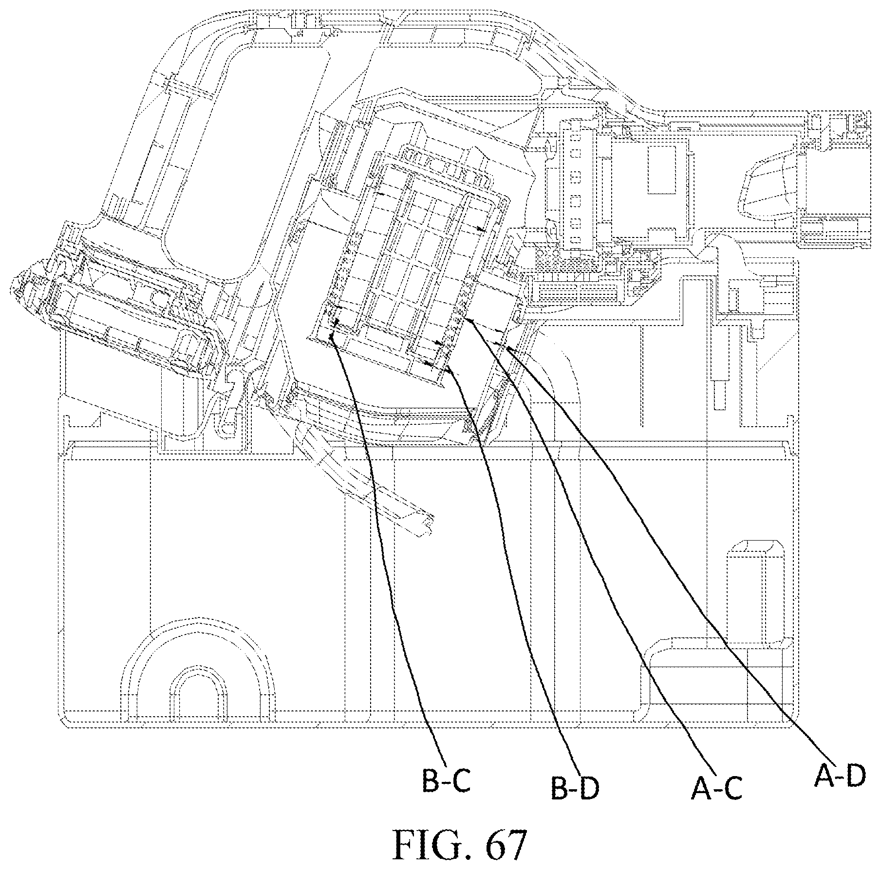
D00068
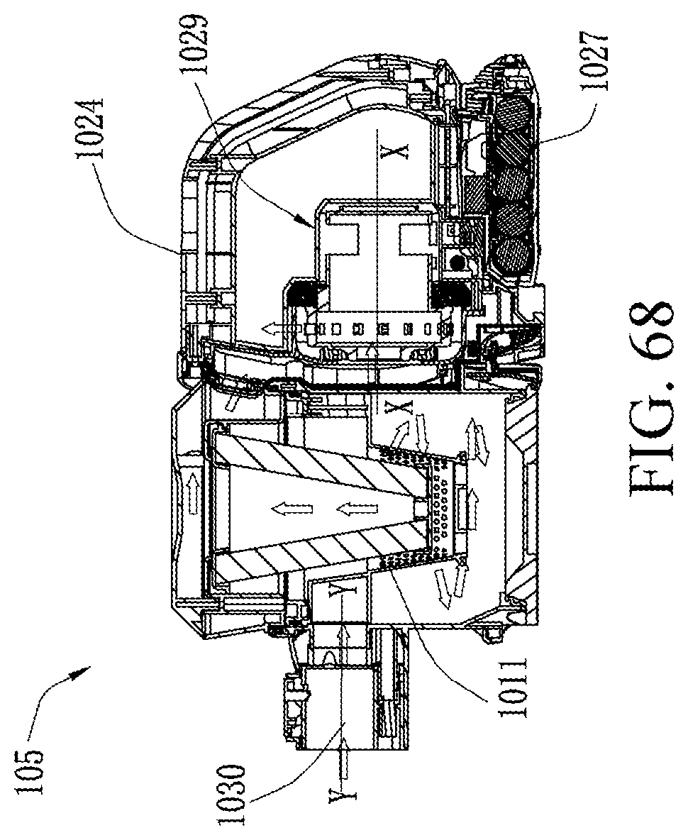
D00069

D00070

D00071
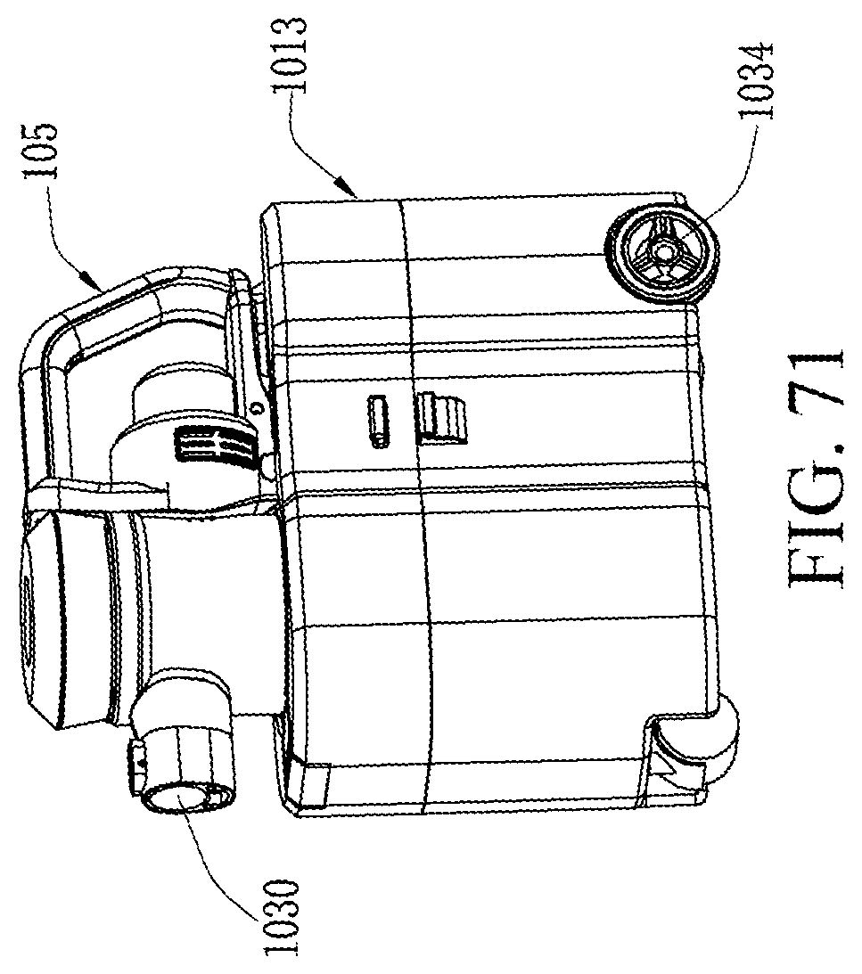
XML
uspto.report is an independent third-party trademark research tool that is not affiliated, endorsed, or sponsored by the United States Patent and Trademark Office (USPTO) or any other governmental organization. The information provided by uspto.report is based on publicly available data at the time of writing and is intended for informational purposes only.
While we strive to provide accurate and up-to-date information, we do not guarantee the accuracy, completeness, reliability, or suitability of the information displayed on this site. The use of this site is at your own risk. Any reliance you place on such information is therefore strictly at your own risk.
All official trademark data, including owner information, should be verified by visiting the official USPTO website at www.uspto.gov. This site is not intended to replace professional legal advice and should not be used as a substitute for consulting with a legal professional who is knowledgeable about trademark law.