A Surface Cleaning Apparatus
Pougher; Simon Matthew
U.S. patent application number 16/624669 was filed with the patent office on 2020-04-30 for a surface cleaning apparatus. The applicant listed for this patent is TTI (MACAO COMMERCIAL OFFSHORE) LIMITED. Invention is credited to Simon Matthew Pougher.
| Application Number | 20200129023 16/624669 |
| Document ID | / |
| Family ID | 60950095 |
| Filed Date | 2020-04-30 |


| United States Patent Application | 20200129023 |
| Kind Code | A1 |
| Pougher; Simon Matthew | April 30, 2020 |
A SURFACE CLEANING APPARATUS
Abstract
A surface cleaning apparatus including: a housing supporting: a suction source; a cyclonic separator device for separating dirt from dirt-laden air, wherein the cyclonic separator device has an elongate axis (A) which lies in a plane (Q1); a user graspable handle having an elongate axis (C), a passage member for transporting dirt-laden air to the dirt separation device, the passage member having an elongate axis (B), wherein the elongate axis (B) of the passage member and the elongate axis (C) of the user graspable handle lie in a plane (P1), and the elongate axis (A) of the body intersects the plane (P1), and wherein the cyclonic separator device includes: a first separating chamber fluidly connected to the passage member for separating relatively coarse dust or debris from any dirt-laden air received from the passage member; an inlet through which dirt-laden air is drawn into the first dirt separating chamber; a first dirt collection chamber for receiving dirt separated by the first separating chamber; a shroud; an outlet through which cleaner air exits the first separating chamber; a baffle positioned in the first dirt collection chamber which lies in a plane (R1), and wherein, in side view, the plane (Q1) is perpendicular to the vertical and the baffle is positioned above the plane (Q1) such that, in normal use, dirt collected in the first dirt collection chamber reaches the plane (Q1) before the dirt reaches the baffle.
| Inventors: | Pougher; Simon Matthew; (Chester Cheshire, GB) | ||||||||||
| Applicant: |
|
||||||||||
|---|---|---|---|---|---|---|---|---|---|---|---|
| Family ID: | 60950095 | ||||||||||
| Appl. No.: | 16/624669 | ||||||||||
| Filed: | June 15, 2018 | ||||||||||
| PCT Filed: | June 15, 2018 | ||||||||||
| PCT NO: | PCT/GB2018/051655 | ||||||||||
| 371 Date: | December 19, 2019 |
| Current U.S. Class: | 1/1 |
| Current CPC Class: | A47L 5/12 20130101; A47L 9/1608 20130101; A47L 9/1683 20130101; B04C 5/26 20130101; A47L 9/322 20130101; A47L 9/1409 20130101; A47L 9/1633 20130101; A47L 9/102 20130101; A47L 9/1481 20130101; A47L 9/165 20130101; A47L 9/242 20130101; A47L 9/1691 20130101; A47L 5/28 20130101; A47L 5/36 20130101; A47L 9/248 20130101; A47L 9/327 20130101; A47L 9/1658 20130101; A47L 9/1616 20130101; A47L 5/24 20130101; B04C 5/187 20130101 |
| International Class: | A47L 9/16 20060101 A47L009/16; A47L 9/14 20060101 A47L009/14 |
Foreign Application Data
| Date | Code | Application Number |
|---|---|---|
| Jun 19, 2017 | GB | PCT/GB2017/051786 |
| Jun 19, 2017 | GB | PCT/GB2017/051788 |
| Dec 5, 2017 | GB | 1720287.0 |
Claims
1. A surface cleaning apparatus including: a housing supporting: a suction source; a cyclonic separator device for separating dirt from dirt-laden air, wherein the cyclonic separator device has an elongate axis (A) which lies in a plane (Q1); a user graspable handle having an elongate axis (C), a passage member for transporting dirt-laden air to the dirt separation device, the passage member having an elongate axis (B), wherein the elongate axis (B) of the passage member and the elongate axis (C) of the user graspable handle lie in a plane (P1), and the elongate axis (A) of the cyclonic separator device intersects the plane (P1), and wherein the cyclonic separator device includes: a first separating chamber fluidly connected to the passage member for separating relatively coarse dust or debris from any dirt-laden air received from the passage member; an inlet through which dirt-laden air is drawn into the first dirt separating chamber; a first dirt collection chamber for receiving dirt separated by the first separating chamber; a shroud; an outlet through which cleaner air exits the first separating chamber; a baffle positioned in the first dirt collection chamber which lies in a plane (R1), and wherein, in side view, the plane (Q1) is perpendicular to the vertical and the baffle is positioned above the plane (Q1) such that, in normal use, dirt collected in the first dirt collection chamber reaches the plane (Q1) before the dirt reaches the baffle.
2. A surface cleaning apparatus including: a housing supporting: a suction source; a cyclonic separator device for separating dirt from dirt-laden air, wherein the cyclonic separator device has an elongate axis (A) which lies in a plane (Q1), wherein, in normal use, the housing is supported on a floor surface and the elongate axis (A) of the cyclonic separator device is parallel with the floor surface, and wherein the cyclonic separator device includes: a first separating chamber for separating relatively coarse dust or debris from dirt-laden air; an inlet through which dirt-laden air is drawn into the first dirt separating chamber; a first dirt collection chamber for receiving dirt separated by the first separating chamber; a shroud; an outlet through which cleaner air exits the first separating chamber; a baffle positioned in the first dirt collection chamber which lies in a plane (R1), and wherein, in side view, the plane (Q1) is perpendicular to the vertical and the baffle is positioned above the plane (Q1) such that, in normal use, dirt collected in the first dirt collection chamber reaches the plane (Q1) before the dirt reaches the baffle.
3. A surface cleaning apparatus according to claim 1 or 2 wherein, in side view, the inlet of the first separating chamber is positioned below the plane (Q1), and wherein, an angle formed between the plane (Q1) and plane (R1) is between 30 and 60 degrees.
4. A surface cleaning apparatus according to claim 3 wherein the angle is between 35 and 55 degrees.
5. A surface cleaning apparatus according to claim 4 wherein the angle is between 40 and 45 degrees.
6. A surface cleaning apparatus according to claim 5 wherein the angle is 43 degrees or is about 43 degrees.
7. A surface cleaning apparatus according to claim 1 wherein, in side view, the inlet of the first separator chamber is positioned above the plane (Q1), and wherein, an angle formed between the plane (Q1) and plane (R1) is between 120 and 150 degrees.
8. A surface cleaning apparatus according to claim 7 wherein the angle is between 125 and 145 degrees.
9. A surface cleaning apparatus according to claim 8 wherein the angle is between 130 and 135 degrees.
10. A surface cleaning apparatus according to claim 9 wherein the angle is 133 degrees or is about 133 degrees.
11. A surface cleaning apparatus according to any preceding claim wherein the first dirt collection chamber includes a generally cylindrical portion and the baffle is connected to the generally cylindrical portion or is in abutment with the generally cylindrical portion.
12. A surface cleaning apparatus according to any preceding claim including a cover which defines an inwardly facing end wall of the first dirt collection chamber.
13. A surface cleaning apparatus according to claim 12 wherein the baffle is provided on the cover.
14. A surface cleaning apparatus according to claim 13 wherein the baffle is integrally formed as part of the cover.
15. A surface cleaning apparatus according to any preceding claim wherein the generally cylindrical portion of the first separating chamber has a height H.sub.c, and wherein the baffle extends upwardly from the end wall of the first dirt collection chamber lid a height B.sub.h, wherein the ratio (H.sub.c:B.sub.h) is defined by the range: 1.4:1.ltoreq.H.sub.c:B.sub.h.ltoreq.1.9:1.
16. A surface cleaning apparatus according to claim 15 wherein (H.sub.c:B.sub.h) is defined by the range: 1.6:1.ltoreq.H.sub.c:B.sub.h.ltoreq.1.8:1.
17. A surface cleaning apparatus according to claim 16 wherein (H.sub.c:B.sub.h) is or is about 1.7.
18. A surface cleaning apparatus according to any preceding claim wherein the baffle extends from the first generally cylindrical portion in a radial direction towards elongate axis (A).
19. A surface cleaning apparatus according to claim 18 wherein the baffle extends a radial distance B.sub.r and wherein the first dirt collection chamber has a diameter D.sub.r, wherein the ratio (D.sub.r:B.sub.r) is defined by the range: 3:1.ltoreq.D.sub.r:B.sub.r.ltoreq.6:1.
20. A surface cleaning apparatus according to claim 19 wherein the ratio (D.sub.r:B.sub.r) is defined by the range: 3:1.ltoreq.D.sub.r:B.sub.r.ltoreq.5:1.
21. A surface cleaning apparatus according to claim 20 wherein (D.sub.r:B.sub.r) is or is about 4.
22. A cyclonic separator device for separating dirt from dirt-laden air, the cyclonic separator device including: a first separating chamber for separating relatively coarse dust or debris from dirt-laden air; an inlet through which dirt-laden air is drawn into the first dirt separating chamber; a first dirt collection chamber for receiving dirt separated by the first separating chamber; a shroud; an outlet through which cleaner air exits the first separating chamber; a baffle positioned in the first dirt collection chamber which lies in a plane (R1), wherein the generally cylindrical portion of the first separating chamber has a height H.sub.c, and wherein the baffle extends upwardly from the end wall of the first dirt collection chamber lid a height B.sub.h, wherein the ratio (H.sub.c:B.sub.h) is defined by the range: 1.4:1.ltoreq.H.sub.c:B.sub.h.ltoreq.1.9:1.
23. A cyclonic separator device according to claim 22 wherein (H.sub.c:B.sub.h) is defined by the range: 1.6:1.ltoreq.H.sub.c:B.sub.h.ltoreq.1.8:1.
24. A cyclonic separator device according to claim 23 wherein (H.sub.c:B.sub.h) is or is about 1.7.
25. A cyclonic separator device according to any one of claims 22 to 24 wherein the baffle extends from the first generally cylindrical portion in a radial direction towards elongate axis (A), the baffle extends a radial distance B.sub.r and a diameter of the first dirt collection chamber is D.sub.r, and wherein the ratio (D.sub.r:B.sub.r) is defined by the range: 3:1.ltoreq.D.sub.r:B.sub.r.ltoreq.6:1.
26. A cyclonic separator device according to claim 25 wherein the ratio (D.sub.r:B.sub.r) is defined by the range: 3:1.ltoreq.D.sub.r:B.sub.r.ltoreq.5:1.
27. A cyclonic separator device according to claim 26 wherein (D.sub.r:B.sub.r) is or is about 4.
28. A cyclonic separator device for separating dirt from dirt-laden air, the cyclonic separator device including: a first separating chamber for separating relatively coarse dust or debris from any dirt-laden air received from the passage member; an inlet through which dirt-laden air is drawn into the first dirt separating chamber; a first dirt collection chamber for receiving dirt separated by the first separating chamber; a shroud; an outlet through which cleaner air exits the first separating chamber; a baffle positioned in the first dirt collection chamber which lies in a plane (R1), wherein the baffle extends from the first generally cylindrical portion in a radial direction towards elongate axis (A) a radial distance B.sub.r and wherein a diameter of the first dirt collection chamber is D.sub.r, wherein the ratio (D.sub.r:B.sub.r) is defined by the range: 3:1.ltoreq.D.sub.r:B.sub.r.ltoreq.6:1.
29. A cyclonic separator device according to claim 28 wherein the ratio (D.sub.r:B.sub.r) is defined by the range: 3:1.ltoreq.D.sub.r:B.sub.r.ltoreq.5:1.
30. A cyclonic separator device according to claim 29 wherein (D.sub.r:B.sub.r) is or is about 4.
31. A surface cleaning apparatus or cyclonic separator device according to any preceding claim wherein the cyclonic separator device includes: a second separating chamber positioned generally within the shroud for separating relatively fine dirt from the dirt-laden air cleaned by the first separating chamber, a second dirt collection chamber in communication with the second separating chamber; an outlet through which cleaner air exits the second separating chamber; wherein the first separating chamber includes a generally cylindrical portion with a central axis and wherein the inlet is configured to direct the incoming dirt-laden air into said generally cylindrical portion such that it travels circumferentially around an inner surface of the first separating chamber, wherein the shroud is positioned generally centrally of the generally cylindrical portion of the first separating chamber and the shroud has a generally cylindrical portion having a height D with openings therein for the passage of air therethrough towards the second separating chamber, wherein the second separating chamber includes: an inlet through which cleaned dirt-laden air exiting the first separating chamber is drawn into the second separating chamber; and a generally frusto-conical portion with a central axis and the generally frusto-conical portion has an end part in communication with the second dirt collection chamber through which fine dirt exits therethrough into the second dirt collection chamber, and wherein the inlet of the second separating chamber is configured to direct the incoming said cleaned dirt-laden air such that it travels circumferentially around an inner surface of the generally frusto-conical portion.
32. A surface cleaning apparatus according to any preceding claim including: a surface cleaning tool; an elongate member having an elongate axis, said elongate member connecting the surface cleaning tool to the housing and including a passage for carrying dirt-laden air from the surface cleaning tool to the dirt collection chamber.
33. A surface cleaning apparatus according to any preceding claim wherein the apparatus is a handheld apparatus.
34. Any novel feature or novel combination of features described herein and/or in the accompanying drawings.
Description
DESCRIPTION OF INVENTION
[0001] This invention relates to a surface cleaning apparatus including a cyclonic separation device.
[0002] In more detail, the invention relates to improving the performance of a cyclonic separating device by optimising certain characteristics and dimensions of certain parts of the device, for example, in relation to optimising the performance of a cyclonic separating device which is horizontal or otherwise inclined in normal use.
[0003] According to an aspect of the present invention we provide a surface cleaning apparatus including: [0004] a housing supporting: [0005] a suction source; [0006] a cyclonic separator device for separating dirt from dirt-laden air, wherein the cyclonic separator device has an elongate axis (A) which lies in a plane (Q1); [0007] a user graspable handle having an elongate axis (C), [0008] a passage member for transporting dirt-laden air to the dirt separation device, the passage member having an elongate axis (B), [0009] wherein the elongate axis (B) of the passage member and the elongate axis (C) of the user graspable handle lie in a plane (P1), and the elongate axis (A) of the cyclonic separator device intersects the plane (P1), and [0010] wherein the cyclonic separator device includes: [0011] a first separating chamber fluidly connected to the passage member for separating relatively coarse dust or debris from any dirt-laden air received from the passage member; [0012] an inlet through which dirt-laden air is drawn into the first dirt separating chamber; [0013] a first dirt collection chamber for receiving dirt separated by the first separating chamber; [0014] a shroud; [0015] an outlet through which cleaner air exits the first separating chamber; [0016] a baffle positioned in the first dirt collection chamber which lies in a plane (R1), and [0017] wherein, in side view, the plane (Q1) is perpendicular to the vertical and the baffle is positioned above the plane (Q1) such that, in normal use, dirt collected in the first dirt collection chamber reaches the plane (Q1) before the dirt reaches the baffle.
[0018] According to an aspect of the present invention we provide a surface cleaning apparatus including: [0019] a housing supporting: [0020] a suction source; [0021] a cyclonic separator device for separating dirt from dirt-laden air, wherein the cyclonic separator device has an elongate axis (A) which lies in a plane (Q1), wherein, in normal use, the housing is supported on a floor surface and the elongate axis (A) of the cyclonic separator device is parallel with the floor surface, and [0022] wherein the cyclonic separator device includes: [0023] a first separating chamber for separating relatively coarse dust or debris from dirt-laden air; [0024] an inlet through which dirt-laden air is drawn into the first dirt separating chamber; [0025] a first dirt collection chamber for receiving dirt separated by the first separating chamber; [0026] a shroud; [0027] an outlet through which cleaner air exits the first separating chamber; [0028] a baffle positioned in the first dirt collection chamber which lies in a plane (R1), and [0029] wherein, in side view, the plane (Q1) is perpendicular to the vertical and the baffle is positioned above the plane (Q1) such that, in normal use, dirt collected in the first dirt collection chamber reaches the plane (Q1) before the dirt reaches the baffle.
[0030] Optionally in side view, the inlet of the first separating chamber is positioned below the plane (Q1), and wherein, an angle formed between the plane (Q1) and plane (R1) is between 30 and 60 degrees.
[0031] Optionally the angle is between 35 and 55 degrees.
[0032] Optionally the angle is between 40 and 45 degrees.
[0033] Optionally the angle is 43 degrees or is about 43 degrees.
[0034] Optionally in side view, the inlet of the first separator chamber is positioned above the plane (Q1), and wherein, an angle formed between the plane (Q1) and plane (R1) is between 120 and 150 degrees.
[0035] Optionally the angle is between 125 and 145 degrees.
[0036] Optionally the angle is between 130 and 135 degrees.
[0037] Optionally the angle is 133 degrees or is about 133 degrees.
[0038] Optionally the first dirt collection chamber includes a generally cylindrical portion and the baffle is connected to the generally cylindrical portion or is in abutment with the generally cylindrical portion.
[0039] Optionally the apparatus includes a cover which defines an inwardly facing end wall of the first dirt collection chamber.
[0040] Optionally the baffle is provided on the cover.
[0041] Optionally the baffle is integrally formed as part of the cover.
[0042] Optionally the generally cylindrical portion of the first separating chamber has a height H.sub.c, and wherein the baffle extends upwardly from the end wall of the first dirt collection chamber lid a height B.sub.h, wherein the ratio (H.sub.c:B.sub.h) is defined by the range: [0043] 1.4:1.ltoreq.H.sub.c:B.sub.h.ltoreq.1.9:1.
[0044] Optionally (H.sub.c:B.sub.h) is defined by the range: [0045] 1.6:1.ltoreq.H.sub.c:B.sub.h.ltoreq.1.8:1.
[0046] Optionally (H.sub.c:B.sub.h) is or is about 1.7.
[0047] Optionally the baffle extends from the first generally cylindrical portion in a radial direction towards elongate axis (A).
[0048] Optionally the baffle extends a radial distance B.sub.r and wherein the first dirt collection chamber has a diameter D.sub.r, wherein the ratio (D.sub.r:B.sub.r) is defined by the range: [0049] 3:1.ltoreq.D.sub.r:B.sub.r.ltoreq.6:1.
[0050] Optionally the ratio (D.sub.r:B.sub.r) is defined by the range: [0051] 3:1.ltoreq.D.sub.r:B.sub.r.ltoreq.5:1.
[0052] Optionally (D.sub.r:B.sub.r) is or is about 4.
[0053] According to an aspect of the present invention we provide a cyclonic separator device for separating dirt from dirt-laden air, the cyclonic separator device including: [0054] a first separating chamber for separating relatively coarse dust or debris from dirt-laden air; [0055] an inlet through which dirt-laden air is drawn into the first dirt separating chamber; [0056] a first dirt collection chamber for receiving dirt separated by the first separating chamber; [0057] a shroud; [0058] an outlet through which cleaner air exits the first separating chamber; [0059] a baffle positioned in the first dirt collection chamber which lies in a plane (R1), [0060] wherein the generally cylindrical portion of the first separating chamber has a height H.sub.c, and wherein the baffle extends upwardly from the end wall of the first dirt collection chamber lid a height B.sub.h, wherein the ratio (H.sub.c:B.sub.h) is defined by the range: [0061] 1.4:1.ltoreq.H.sub.c:B.sub.h.ltoreq.1.9:1.
[0062] Optionally (H.sub.c:B.sub.h) is defined by the range: [0063] 1.6:1.ltoreq.H.sub.c:B.sub.h.ltoreq.1.8:1.
[0064] Optionally (H.sub.c:B.sub.h) is or is about 1.7.
[0065] Optionally the baffle extends from the first generally cylindrical portion in a radial direction towards elongate axis (A), the baffle extends a radial distance B.sub.r and a diameter of the first dirt collection chamber is D.sub.r, and [0066] wherein the ratio (D.sub.r:B.sub.r) is defined by the range: [0067] 3:1.ltoreq.D.sub.r:B.sub.r.ltoreq.6:1.
[0068] Optionally the ratio (D.sub.r:B.sub.r) is defined by the range: [0069] 3:1.ltoreq.D.sub.r:B.sub.r.ltoreq.5:1.
[0070] Optionally (D.sub.r:B.sub.r) is or is about 4.
[0071] According to an aspect of the present invention we provide a cyclonic separator device for separating dirt from dirt-laden air, the cyclonic separator device including: [0072] a first separating chamber for separating relatively coarse dust or debris from any dirt-laden air received from the passage member; [0073] an inlet through which dirt-laden air is drawn into the first dirt separating chamber; [0074] a first dirt collection chamber for receiving dirt separated by the first separating chamber; [0075] a shroud; [0076] an outlet through which cleaner air exits the first separating chamber; [0077] a baffle positioned in the first dirt collection chamber which lies in a plane (R1), [0078] wherein the baffle extends from the first generally cylindrical portion in a radial direction towards elongate axis (A) a radial distance B.sub.r and wherein a diameter of the first dirt collection chamber is D.sub.r, [0079] wherein the ratio (D.sub.r:B.sub.r) is defined by the range: [0080] 3:1.ltoreq.D.sub.r:B.sub.r.ltoreq.6:1.
[0081] Optionally the ratio (D.sub.r:B.sub.r) is defined by the range: [0082] 3:1.ltoreq.D.sub.r:B.sub.r.ltoreq.5:1.
[0083] Optionally (D.sub.r:B.sub.r) is or is about 4.
[0084] Optionally the cyclonic separator device includes: [0085] a second separating chamber positioned generally within the shroud for separating relatively fine dirt from the dirt-laden air cleaned by the first separating chamber, [0086] a second dirt collection chamber in communication with the second separating chamber; [0087] an outlet through which cleaner air exits the second separating chamber; [0088] wherein the first separating chamber includes a generally cylindrical portion with a central axis and wherein the inlet is configured to direct the incoming dirt-laden air into said generally cylindrical portion such that it travels circumferentially around an inner surface of the first separating chamber, [0089] wherein the shroud is positioned generally centrally of the generally cylindrical portion of the first separating chamber and the shroud has a generally cylindrical portion having a height D with openings therein for the passage of air therethrough towards the second separating chamber, [0090] wherein the second separating chamber includes: [0091] an inlet through which cleaned dirt-laden air exiting the first separating chamber is drawn into the second separating chamber; and [0092] a generally frusto-conical portion with a central axis and the generally frusto-conical portion has an end part in communication with the second dirt collection chamber through which fine dirt exits therethrough into the second dirt collection chamber, and wherein the inlet of the second separating chamber is configured to direct the incoming said cleaned dirt-laden air such that it travels circumferentially around an inner surface of the generally frusto-conical portion.
[0093] A surface cleaning apparatus according to any preceding or aspect/optional aspect including: [0094] a surface cleaning tool; [0095] an elongate member having an elongate axis, said elongate member connecting the surface cleaning tool to the housing and including a passage for carrying dirt-laden air from the surface cleaning tool to the dirt collection chamber.
[0096] Optionally the apparatus is a handheld apparatus.
[0097] Embodiments of the invention will be set out below by way of example only with reference to the accompanying figures, of which:
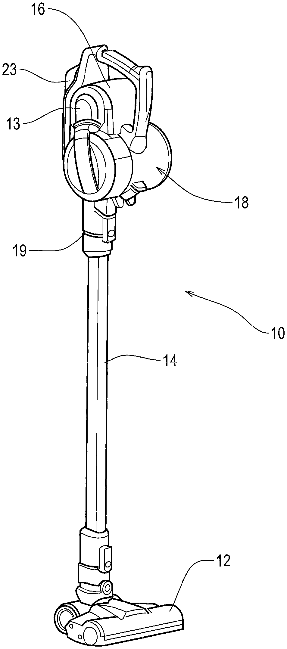
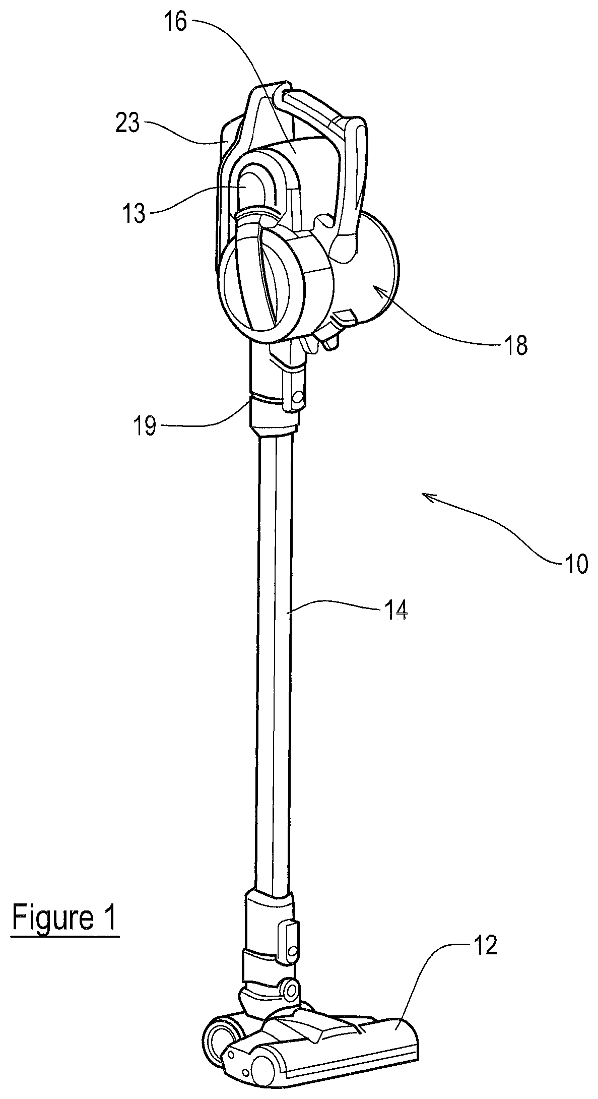
[0098] FIG. 1 is a perspective view of a surface cleaning apparatus;
[0099] FIG. 2 is a front view of the apparatus of FIG. 1;
[0100] FIG. 3 is a side view of the apparatus FIG. 1;
[0101] FIG. 4 is a perspective view of a housing of the apparatus of FIG. 1, which housing is operable as a handheld surface cleaning apparatus;
[0102] FIG. 5 is a side view of the housing of FIG. 4;
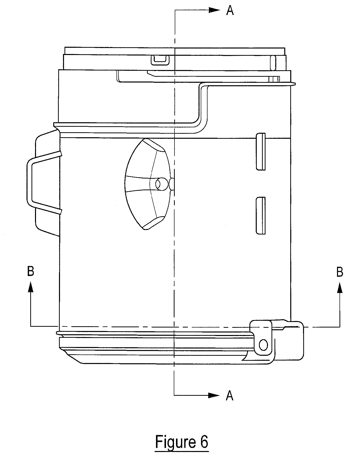
[0103] FIG. 6 is a side view of a component of the apparatus of FIG. 1;
[0104] FIG. 7 is a cross-sectional view A-A of the component of FIG. 6;
[0105] FIG. 8 is a cross-sectional view B-B of the component of FIG. 6;
[0106] FIG. 9 is a cross-sectional view of a component of an embodiment of the invention, and
[0107] FIG. 10 is a cross-sectional view of the housing of FIG. 4.
[0108] Referring to the figures, these show a surface cleaning apparatus 10 in accordance with the present invention. The apparatus 10 includes a surface cleaning tool 12 (a floor head in this example), a housing 16 having an elongate axis H and an elongate member 14, having an elongate axis E, connecting the surface cleaning tool 12 to the housing 16. The elongate member 14 is relatively rigid. The housing 16, in this example, is operable as a handheld surface cleaning apparatus, commonly known as a hand vac, when the elongate member 14 is not connected thereto, and in this state the housing 16 can be used with or without the surface cleaning tool 12 connected thereto. The housing 16 supports a suction source 13 and a dirt separation device 15 including a cyclonic separator device 18. The cyclonic separator device 18 is generally cylindrical and has an elongate axis A. The axis A is the axis about which dirt-laden air is caused to rotate by the cyclonic separator as it passes through the apparatus 10. The cyclonic separator device 18 also includes a filter 84 for cleaning the relatively clean air emitted by the cyclonic separator device 18. In embodiments, the suction source 13 is an electric motor driving a rotatable fan, but any appropriate suction source may be used. All that is necessary is for the suction source to be able to draw air through the surface cleaning tool 12 and elongate member 14 towards the cyclonic separator device 18.
[0109] In embodiments, the housing 16 supports or contains a battery 23 to provide electrical power to the suction motor and other components of the apparatus 10. The battery 23 is of a generally elongate shape but may be of a different shape in other embodiments.
[0110] In embodiments, the housing 16 includes a passage member 19 in fluid communication with the cyclonic separator device 18. The passage member 19 is generally elongate. Passage member 19 has an elongate axis B. A first end of the passage member 19 defines an inlet 17 for receiving dirt-laden air. The first end is connectable to the elongate member 14 or surface cleaning tool 12. When connected, axis B is parallel to the elongate axis E of the elongate member 14. In embodiments, axis B may be co-axial or offset from the elongate axis E.
[0111] In embodiments, the cyclonic separator device 18 includes an inlet passage member 28 for fluidly connecting the passage member 19 to the cyclonic separation device 18. In embodiments, there may be no inlet passage member 28 and instead the passage member 19 communicates with an inlet of the cyclonic separator device directly. In other embodiments, the housing 16 has no passage member and the inlet passage member 28 is formed as part of the dirt separation device 15 and connects to a tool or elongate member directly.
[0112] The elongate member 14 includes a passage for carrying dirt-laden air from the surface cleaning tool 12 to the dirt separation device. In this example the surface cleaning tool 12 includes a motor for driving a rotatable floor agitating member or brush, so the elongate member 14 includes a further passage through which electrical cables may extend to provide an electric connection between the housing 16 and the motor in the surface cleaning tool 12.
[0113] The surface cleaning tool 12 is disconnectable from the elongate member 14, so that, for example, another tool can be connected to the free end of the elongate member 14. The elongate member 14 is also disconnectable from the housing 16, by way of a manually operated switch 17a. This enables the housing 16 to be used as a handheld surface cleaning apparatus, with the option of being able to connect another tool to the location from where the elongate member 14 is removed.
[0114] The housing 16 includes a handle for holding the apparatus 10, said handle including first 20 and second 21 user-graspable portions which are connected to each other substantially at right-angles. The dirt separation device 15 is positioned forwardly of the handle. A first end of the first user-graspable portion 20 is connected to the housing 16 and the portion 20 extends generally upwardly and away therefrom. The user-graspable portion 20 has an elongate axis C. A first end of the second user-graspable portion 21 is connected to the housing 16 and extends generally rearwardly away therefrom and from the elongate member 14. Respective second ends of the first 20 and second 21 user-graspable portions are connected to each other. Essentially, the first 20 and second 21 user-graspable portions form a handle which is L-shaped and which provides two locations each of which is sized such that it can be grasped fully by a hand of a user. A device 22a, e.g. a switch, for turning the apparatus "on" is positioned at the connection of the second ends of the first 20 and second 21 user-graspable portions to each other.
[0115] The suction source 13 is in the form of an electric motor 30 with an axle which is connected at one end to a fan. The motor 30 may be any appropriate motor, e.g. DC, AC, brushless.
[0116] An upstream wall 112 of the housing 16 extends along the elongate axis H of the housing 16 and has an inner surface which partially defines an air flow passage from an outlet 104 of the dirt separation device to an inlet 103 of the suction source 13. In more detail, an inlet passage 37a to the suction source 13 defines an inlet 103 at an end face thereof and the upstream wall 112 defines an outlet 114 at an end face thereof. The end face of passage 37a is provided with a seal which abuts the end face of outlet 114 in a sealing manner when the dirt separation device 15 is attached to the housing 16.
[0117] The cyclonic separator device 18 has a first end including the cover 18a and a second end including the upstream wall 112. A cylindrical wall 33 extends between the first and second ends. A portion of the surface of the wall 33 is received by a correspondingly shaped recessed surface of the housing 16.
[0118] The cyclonic separator device 18 has first and second dirt collection chambers 18b, 18e provided at one end 107a thereof.
[0119] The cyclonic separator device 18 has first and second separating chambers 18c, 18d adjacent the first and second dirt collection chambers 18b, 18e. By referring to chambers 18a, 18d, 18b, 18e, it should be understood that the chambers include walls provided by various components and that those walls define respective one or more surfaces and spaces of the chambers.
[0120] The cyclonic separator device 18 includes a shroud 100 which also has an elongate axis coaxial with the axis A, the axis A being that about which dirt-laden air is caused to rotate as it passes through the apparatus 10 and circulates around the shroud 100. The shroud 100 is positioned as part of the cyclonic separator device 18 at an end 107b thereof which is opposite to the end 107a of the cyclonic separator device 18 at which the first and second dirt collection chambers 18b, 18c are provided. The shroud 100 has a skirt 101 with a free distal end. Shroud 100 has a generally cylindrical portion 102 having openings therein for the passage of air positioned generally centrally of the cyclonic separating device 18.
[0121] The first separating chamber 18c is for separating relatively coarse dust or debris from the dirt-laden air. The first separating chamber 18c is in communication with the first dirt collection chamber 18b so that separated dust or debris falls into the first dirt collection chamber 18b therefrom.
[0122] The second separating chamber 18d is positioned generally within the shroud 100 and is for separating relatively fine dust or debris from the dirt-laden air cleaned by the first separating chamber 18c. The second separating chamber 18d is in communication with the second dirt collection chamber 18e so that separated dust or debris falls into the second dirt collection chamber 18e therefrom.
[0123] The cyclonic separator device 18 includes an inlet 99a through which dirt-laden air is drawn into the first separating chamber 18c. The inlet 99a is configured to direct the incoming dirt-laden air into a generally cylindrical portion of the first separating chamber 18c such that it travels circumferentially around an inner surface 19a of the first separating chamber 18c. Whilst in this embodiment the elongate axes of the dirt collection chambers 18c, 18e and the shroud 100 are coaxial or substantially coaxial, they need not be. They could, for example, be parallel and offset from each other or inclined relative to each other. Alternatively, the shroud 100 could be positioned generally centrally of the generally cylindrical portion of one or both of the separating chambers 18c, 18e.
[0124] The cyclonic separator device 18 includes an inlet 99b through which cleaned dirt-laden air exiting the first separating chamber 18c is drawn into the second separating chamber 18d. The second separating chamber 18d includes a generally frusto-conical portion 50 with a central axis. The frusto-conical portion 50 has an end part 52 in communication with the second dirt collection chamber 18e through which fine dust or debris exits therethrough into the second dirt collection chamber 18e.
[0125] The inlet 99b of the second separating chamber 18c is configured to direct the incoming cleaned dirt-laden air such that it travels circumferentially around an inner surface 54 of the generally frusto-conical portion 50. The use of such a frusto-conical portion 50 may permit the second separating chamber 18d to separate finer dust or debris from the air than that achievable by the first separating chamber 18c.
[0126] The second dirt collection chamber 18e includes a first portion 56 positioned near the end part 52 of the generally frusto-conical portion 50 and a second portion 58 connected to the first portion 56 which extends to an end wall of the cyclonic separator device 18 therefrom. The first and second portions 56, 58 are generally cylindrical with the first portion 56 having a greater cross-sectional area than the second portion 58, i.e. as considered without the portion 50 being positioned therein. In other words, the cross-sectional areas referred to are those defined by the respective inner surfaces of the first and second portions 56, 58 as viewed in side cross-section. In embodiments, the respective areas of the cross-sections may be the same or different. A third portion 60 which is frusto-conical connects the second portion 58 to the first portion 56. The second dirt collection chamber 18e includes a baffle 63 positioned generally centrally thereof. A baffle 62 is provided at end 107a of the cyclonic separator device 18. The first dirt collection chamber 18b includes a generally cylindrical portion and a portion of the baffle 62 abuts the generally cylindrical portion. The cover 18a defines an inwardly facing end wall of the first dirt collection chamber 18b and the baffle 62 is integrally formed as part of the cover.
[0127] The suction source 13 is positioned such that its axle extends transversely to the elongate axis H of the housing 16. The axis of the axle and axis A of the cyclonic separator device 18 extend perpendicularly to the elongate axis H of the housing 16. The axes of the axle and dirt collection chamber 18 are also parallel to one another in this embodiment but they may not be in other embodiments. The elongate axis B of the passage member 19 and the elongate axis C of the first user graspable portion 20 of the handle lie in a plane P1, and the elongate axis A of the cyclonic separator device 18 intersects the plane P1 (as shown in FIGS. 2 and 3). The elongate axis A is substantially horizontal in normal use.
[0128] Normal use of the surface cleaning apparatus 10 refers to use thereof when the elongate member 14 is inclined at an acute angle with respect to the surface being cleaned. In other embodiments for which the surface cleaning apparatus 10 is a cylinder cleaner, the housing supporting dirt separation device 15 may be generally upright with respect to the floor surface during normal use, and the elongate axis A may be parallel with or inclined with respect to the floor surface. For embodiments where the apparatus 10 is an upright cleaner, the housing may be inclined with respect to the floor surface and the elongate axis A may be parallel or inclined with the floor surface during normal use.
[0129] In more detail, elongate axis A lies in a plane Q1. The baffle 62 is generally planar and lies in a plane R1 (see FIG. 8). In side view, the plane Q1 is perpendicular to the vertical and the baffle 62 is positioned above the plane Q1. The baffle 62 is so positioned that during operation such that, in use, dirt collected in the first dirt collection chamber 18b reaches the plane Q1 before the dirt reaches the baffle 62.
[0130] The operation of the baffle 62 will now be described. During normal use of the cyclonic separator device 18, dirt will fall into the first dirt collection chamber 18b under the combined effects of gravity and centrifugal forces such that dirt is collected below the plane Q1 before it accumulates and rises above the plane Q1. The baffle 62 functions in a manner known in the art to retain the dirt within the first dirt collection chamber 18b and to prevent it from re-entering the airflow. Advantageously, by having the baffle 62 positioned above the plane Q1, the surfaces of the baffle 62 are not obstructed by dirt collected in the first dirt collection chamber 18b until the amount of dirt collected is such that it rises above the plane Q1. This means that the baffle 62 continues to perform its function for longer.
[0131] With reference to FIG. 8, in embodiments for which, in side view, the inlet 99a of the first separating chamber 18c is positioned below the plane Q1, i.e. the air is rotated in an anti-clockwise direction around the cyclonic separating device, it has been found that pronounced improvements in the performance of the baffle occur when an angle .THETA. formed between the plane Q1 and plane R1 lies in the range 30 to 60 degrees. Further improvements are found if the angle .THETA. lies in the range 35 to 55 degrees. More improvements are found if .THETA. lies in the range 40 to 45 degrees. It has been discovered that a particularly advantageous value of e is 43 degrees or is about 43 degrees.
[0132] FIG. 9 shows a cross-sectional view of a dirt separation device 15 according to embodiments for which, in side view, the inlet 99a of the first separator chamber is positioned above the plane Q1, i.e. the air is rotated in a clockwise direction around the cyclonic separating device. For such embodiments, it has been found that pronounced improvements in the performance of the baffle occur when an angle .THETA. formed between the plane Q1 and plane R1 lies in the range 120 to 150 degrees. Further improvements are found if the angle .THETA. lies in the range 125 to 145 degrees. More improvements are found if .THETA. lies in the range 130 to 135 degrees. It has been discovered that a particularly advantageous value of e is 133 degrees or is about 133 degrees.
[0133] The inventors have discovered that, in embodiments, the use of a single baffle as described, as opposed to a plurality of baffles, prevents the entrailment of dirt from the first dirt collection chamber into the air during operation to a satisfactory degree without requiring further baffles.
[0134] A height H.sub.c of the cylindrical wall 80 of the first separating chamber 18c is defined with reference to the free end of the shroud skirt 101 and where an upper portion of the shroud 100 seals against the first separating chamber 18c.
[0135] It has been found that advantageous performance may occur for embodiments in which height H.sub.c of the generally cylindrical portion of the first separating chamber is 60-70 mm, optionally or preferably 62-68 mm, or optionally or preferably the height H.sub.c is 65 mm. Further improvements are found if a height B.sub.h that the baffle 62 extends upwardly from the end wall of the first dirt collection chamber 18b is 38-44 mm, optionally or preferably 38-41 mm, or optionally or preferably the height B.sub.h is 39 mm.
[0136] The inventors have also discovered advantageous synergies between H.sub.c and B.sub.h. For example, in embodiments, improvements are found when the ratio (H.sub.c:B.sub.h) is defined by the range: [0137] 1.4:1.ltoreq.H.sub.c:B.sub.h.ltoreq.1.9:1.
[0138] Performance improvements are also found when the ratio (H.sub.c:B.sub.h) is defined by the range: [0139] 1.6:1.ltoreq.H.sub.c:B.sub.h.ltoreq.1.8:1.
[0140] Performance improvements are also found when the ratio (H.sub.c:B.sub.h) is or is about 1.7.
[0141] Additionally, advantageously it has been found that performance may be increased for embodiments in which a radial distance B.sub.r extended by the baffle 62 in a radial direction towards the elongate axis A is 12-18 mm, optionally or preferably 14-16 mm, optionally or preferably B.sub.r is 15 mm. Further improvements are found if a radius D.sub.r of the internal surface of the first dirt collection chamber 18 is 55-65 mm, optionally or preferably 59-62 mm, or optionally or preferably the D.sub.r is 61 mm.
[0142] The inventors have also discovered advantageous synergies between B.sub.r and a diameter D.sub.r. For example, in embodiments, improvements are found when the ratio (D.sub.r:B.sub.r) is defined by the range: [0143] 3:1.ltoreq.D.sub.r:B.sub.r.ltoreq.6:1.
[0144] Performance improvements are also found when the ratio (D.sub.r:B.sub.r) is defined by the range: [0145] 3:1.ltoreq.D.sub.r:B.sub.r.ltoreq.5:1.
[0146] Performance improvements are also found when the ratio (D.sub.r:B.sub.r) is or is about 4.
[0147] The advantageous dimensions and ratios described provide advantageous performance for embodiments having a single baffle embodying the described dimensions/ratios or a plurality of baffles embodying the described dimensions/ratios. Furthermore, the associated advantageous performance may be obtainable for cyclonic separators that are not horizontal in normal use.
[0148] The present invention may be realised for cylinder cleaner embodiments including a housing supporting a suction source, a cyclonic separator device having a body with an elongate axis A which lies in a plane Q1 and for which, in normal use, the housing is supported on a floor surface and the elongate axis (A) of the body is parallel with the floor surface. In such embodiments, a baffle is positioned in the first dirt collection chamber which lies in a plane (R1), and, in side view, the plane Q1 is perpendicular to the vertical and the baffle is positioned above the plane Q1.
[0149] Embodiments of the present invention need not have first and second separating chambers and associated first and second dirt collection chambers. Such embodiments may only have a first separating chamber and associated first dirt collection chamber.
[0150] When used in this specification and claims, the terms "comprises" and "comprising" and variations thereof mean that the specified features, steps or integers are included. The terms are not to be interpreted to exclude the presence of other features, steps or components.
[0151] The features disclosed in the foregoing description, or the following claims, or the accompanying drawings, expressed in their specific forms or in terms of a means for performing the disclosed function, or a method or process for attaining the disclosed result, as appropriate, may, separately, or in any combination of such features, be utilised for realising the invention in diverse forms thereof.
* * * * *
D00000
D00001
D00002
D00003
D00004
D00005
D00006
D00007
D00008
D00009
XML
uspto.report is an independent third-party trademark research tool that is not affiliated, endorsed, or sponsored by the United States Patent and Trademark Office (USPTO) or any other governmental organization. The information provided by uspto.report is based on publicly available data at the time of writing and is intended for informational purposes only.
While we strive to provide accurate and up-to-date information, we do not guarantee the accuracy, completeness, reliability, or suitability of the information displayed on this site. The use of this site is at your own risk. Any reliance you place on such information is therefore strictly at your own risk.
All official trademark data, including owner information, should be verified by visiting the official USPTO website at www.uspto.gov. This site is not intended to replace professional legal advice and should not be used as a substitute for consulting with a legal professional who is knowledgeable about trademark law.