Heater And Hair Drying Apparatus
CHEN; Xu ; et al.
U.S. patent application number 16/539414 was filed with the patent office on 2020-04-30 for heater and hair drying apparatus. This patent application is currently assigned to SOOCAS (SHENZHEN) TECHNOLOGY CO., LTD.. The applicant listed for this patent is SOOCAS (SHENZHEN) TECHNOLOGY CO., LTD.. Invention is credited to Xu CHEN, Fandi MENG.
| Application Number | 20200128937 16/539414 |
| Document ID | / |
| Family ID | 70328092 |
| Filed Date | 2020-04-30 |
View All Diagrams
| United States Patent Application | 20200128937 |
| Kind Code | A1 |
| CHEN; Xu ; et al. | April 30, 2020 |
HEATER AND HAIR DRYING APPARATUS
Abstract
The present disclosure relates to a heater and a hair drying apparatus. The heater includes an inner layer including a first end wall, a second end wall, a third end wall and a fourth end wall; the first end wall is arranged opposite to the second end wall; the third end wall is arranged opposite to the fourth end wall; the third end wall and the fourth end wall are respectively connected between the first end wall and the second end wall; and a heating element arranged on the third end wall. Compared with mica material, plastic material possesses better plastic performance with greater hardness. By manufacturing the inner layer of the heater using the plastic material, the inner layer is easier to be set to alternative shapes and fixed to. Therefore, other structural elements are easier to be mounted relative to the inner layer.
| Inventors: | CHEN; Xu; (Shenzhen, CN) ; MENG; Fandi; (Shenzhen, CN) | ||||||||||
| Applicant: |
|
||||||||||
|---|---|---|---|---|---|---|---|---|---|---|---|
| Assignee: | SOOCAS (SHENZHEN) TECHNOLOGY CO.,
LTD. Shenzhen CN |
||||||||||
| Family ID: | 70328092 | ||||||||||
| Appl. No.: | 16/539414 | ||||||||||
| Filed: | August 13, 2019 |
Related U.S. Patent Documents
| Application Number | Filing Date | Patent Number | ||
|---|---|---|---|---|
| PCT/CN2019/087810 | May 21, 2019 | |||
| 16539414 | ||||
| Current U.S. Class: | 1/1 |
| Current CPC Class: | A45D 20/12 20130101 |
| International Class: | A45D 20/12 20060101 A45D020/12 |
Foreign Application Data
| Date | Code | Application Number |
|---|---|---|
| Oct 31, 2018 | CN | 201811298440.4 |
Claims
1. A heater, comprising: an inner layer, which is made of plastic material, including a first end wall, a second end wall, a third end wall and a fourth end wall; the first end wall is arranged opposite to the second end wall; the third end wall is arranged opposite to the fourth end wall; the third end wall and the fourth end wall are respectively connected between the first end wall and the second end wall; and a heating element arranged on the third end wall.
2. The heater of claim 1, wherein the inner layer is of hollow structure, the third end wall forming an external sidewall of the inner layer, the fourth end wall forming an internal sidewall of the inner layer.
3. The heater of claim 1, wherein the inner layer is of annular structure, the third end wall and the fourth end wall respectively extending along an axial direction of the inner layer, the heating element winding around the third end wall.
4. The heater of claim 3, wherein the heater further comprises an outer layer for insulating the heating element, the outer layer being of annular structure and extending around the heating element which is arranged between the third end wall and the outer layer.
5. The heater of claim 4, wherein the outer layer includes a fifth end wall, a sixth end wall, a seventh end wall and an eighth end wall; the fifth end wall is arranged opposite to the sixth end wall; the seventh end wall is arranged opposite to the eighth end wall; the seventh end wall and the eighth end wall are respectively connected between the fifth end wall and the sixth end wall, and extend around the heating element which is arranged between the third end wall and the eighth end wall.
6. The heater of claim 4, wherein the heater further comprises a supporter for supporting the heating element, the supporter being arranged on the third end wall, and extending towards the outer layer along a radial direction of the inner layer.
7. The heater of claim 6, wherein at least one of the supporter and the outer layer is made of insulating material.
8. The heater of claim 6, wherein a plurality of supporters are provided and arranged at intervals around a circumferential direction of the third end wall.
9. The heater of claim 8, wherein at least six supporters are provided and arranged at intervals around the circumferential direction of the third end wall.
10. The heater of claim 6, wherein the supporter provides a locating opening for locating the heating element.
11. The heater of claim 10, wherein a plurality of locating openings are provided and arranged along an identical line on the supporter at intervals, the heating element including multiple turns of coil, each turn being adjacent to another turn; the multiple turns of coil of the heating element are respectively located in the plurality of locating openings.
12. The heater of claim 11, wherein the coil is of zigzag shape or of wave shape.
13. The heater of claim 12, wherein a maximum distance from the coil to the third end wall is 6-9 mm.
14. The heater of claim 12, wherein the coil includes a first bending portion and a second bending portion connected to each other; the first bending portion and the second bending portion both wind around the third end wall, a length of the second bending portion along a circumference direction of the inner layer being greater than that of the first bending portion along a circumference direction of the inner layer.
15. The heater of claim 1, wherein the plastic material is any one of polyphenyl ester, polybenzimidazole, polyboron diphenyl siloxane, polyphenylene sulfide, chlorinated polyether.
16. A hair drying apparatus, comprising a heater which comprises: an inner layer, which is made of plastic material, including a first end wall, a second end wall, a third end wall and a fourth end wall; the first end wall is arranged opposite to the second end wall; the third end wall is arranged opposite to the fourth end wall; the third end wall and the fourth end wall are respectively connected between the first end wall and the second end wall; and a heating element arranged on the third end wall.
Description
CROSS-REFERENCE TO RELATED APPLICATIONS
[0001] This application is a continuation of PCT application No. PCT/CN2019/087810, filed on May 21, 2019, which claims priority of Chinese Application No. 201811298440.4 filed on Oct. 31, 2018. The patent applications are hereby incorporated by reference in their entireties.
TECHNICAL FIELD
[0002] The present disclosure relates to the field of handheld appliances, more particularly, to a heater and a hair drying apparatus.
BACKGROUND
[0003] Hair dryers are mainly used for hair drying and hair conditioning, and also applicable to local drying, heating and physical therapy in laboratories, physical therapy rooms, industrial manufacture and art design.
[0004] Existing heaters of the hair dryers mainly adopt an inner layer made of mica material as a thermal insulation support structure of heating elements thereof, however, the thermal insulation support structure can only be presented in a fixed shape for the limitation of the mica material, which makes it hard for other structural elements to be mounted relative to the thermal insulation support structure, thereby making the hair dryers hard to meet the users' actual use requirements.
SUMMARY
[0005] Based on this, it is necessary to provide a heater and a hair drying apparatus with simple structures and great bearing adaptability performance.
[0006] A heater includes:
[0007] an inner layer, which is made of plastic material, including a first end wall, a second end wall, a third end wall and a fourth end wall; the first end wall is arranged opposite to the second end wall; the third end wall is arranged opposite to the fourth end wall; the third end wall and the fourth end wall are respectively connected between the first end wall and the second end wall; and
[0008] a heating element arranged on the third end wall.
[0009] In one embodiment, the inner layer is of hollow structure, the third end wall forming an external sidewall of the inner layer, the fourth end wall forming an internal sidewall of the inner layer.
[0010] In one embodiment, the inner layer is of annular structure, the third end wall and the fourth end wall respectively extending along an axial direction of the inner layer, the heating element winding around the third end wall.
[0011] In one embodiment, the heater further includes an outer layer for insulating the heating element, the outer layer being of annular structure and extending around the heating element which is arranged between the third end wall and the outer layer.
[0012] In one embodiment, the outer layer includes a fifth end wall, a sixth end wall, a seventh end wall and an eighth end wall; the fifth end wall is arranged opposite to the sixth end wall; the seventh end wall is arranged opposite to the eighth end wall; the seventh end wall and the eighth end wall are respectively connected between the fifth end wall and the sixth end wall, and extend around the heating element which is arranged between the third end wall and the eighth end wall.
[0013] In one embodiment, the heater further includes a supporter for supporting the heating element, the supporter being arranged on the third end wall, and extending towards the outer layer along a radial direction of the inner layer.
[0014] In one embodiment, at least one of the supporter and the outer layer is made of insulating material.
[0015] In one embodiment, a plurality of supporters are provided and arranged at intervals around a circumferential direction of the third end wall.
[0016] In one embodiment, at least six supporters are provided and arranged at intervals around the circumferential direction of the third end wall.
[0017] In one embodiment, the supporter provides a locating opening for locating the heating element.
[0018] In one embodiment, a plurality of locating openings are provided and arranged along an identical line on the supporter at intervals, the heating element including multiple turns of coil, each turn being adjacent to another turn; the multiple turns of coil of the heating element are respectively located in the plurality of locating openings.
[0019] In one embodiment, the coil is of zigzag shape or of wave shape.
[0020] In one embodiment, a maximum distance from the coil to the third end wall is 6-9 mm.
[0021] In one embodiment, the coil includes a first bending portion and a second bending portion connected to each other; the first bending portion and the second bending portion both wind around the third end wall, a length of the second bending portion along a circumference direction of the inner layer being greater than that of the first bending portion along a circumference direction of the inner layer.
[0022] In one embodiment, the plastic material is any one of polyphenyl ester, polybenzimidazole, polyboron diphenyl siloxane, polyphenylene sulfide, chlorinated polyether.
[0023] A hair drying apparatus includes the heater described above.
[0024] Compared with mica material, plastic material possesses better plastic performance with greater hardness. By manufacturing the inner layer of the heater using the plastic material, the inner layer, as the heat insulation support structure of the heating elements, is easier to be set to alternative shapes and fixed to. Therefore, other structural elements are easier to be mounted relative to the inner layer which acts as the thermal insulation support structure of the heating element, thereby substantially improving the bearing adaptability performance.
BRIEF DESCRIPTION OF THE ACCOMPANYING DRAWINGS
[0025] In order to explain the technical solutions of the present disclosure and of the prior art more clearly, the following drawings required in the embodiment and the prior art will be introduced briefly. Apparently, the following drawings merely represent some embodiments of the present disclosure. For those ordinarily skilled in the art, drawings which show alternative embodiments may be derived from the following drawings without paying creative works.
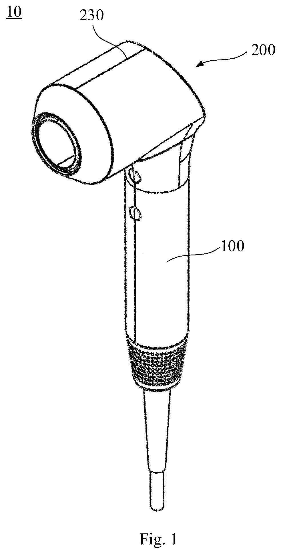
[0026] FIG. 1 is a structural view of a hair drying apparatus according to an embodiment;
[0027] FIG. 2 is a cross-section view of the hair drying apparatus shown in FIG. 1;
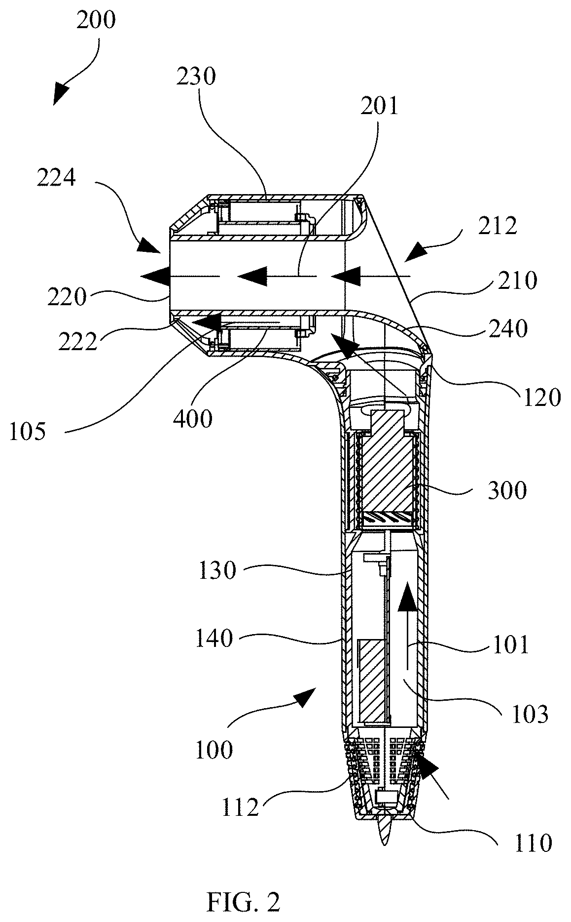
[0028] FIG. 3 is a structural view of a heating element of the hair drying apparatus shown in FIG. 1;
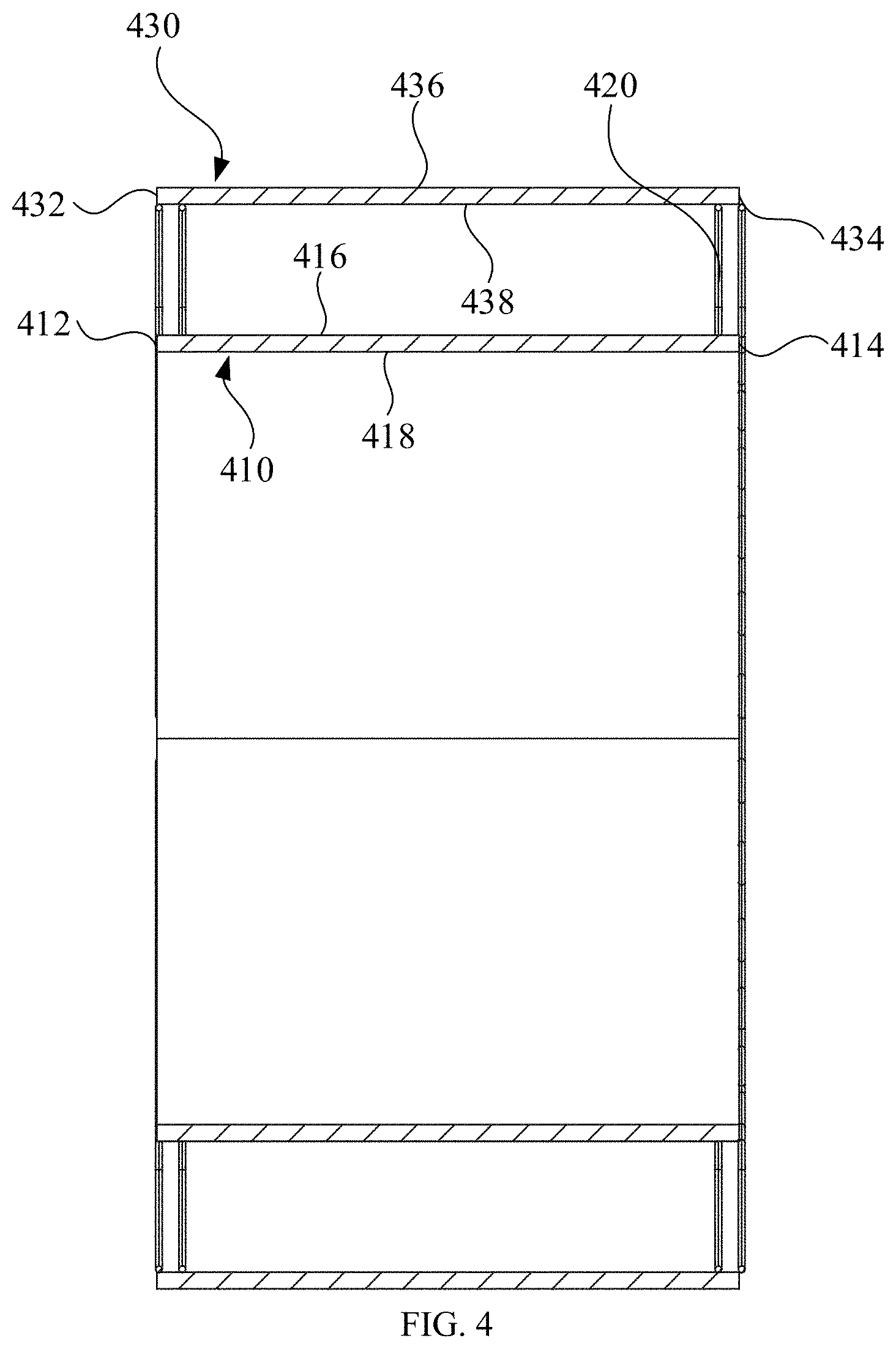
[0029] FIG. 4 is a cross-section view of the heating element shown in FIG. 3;
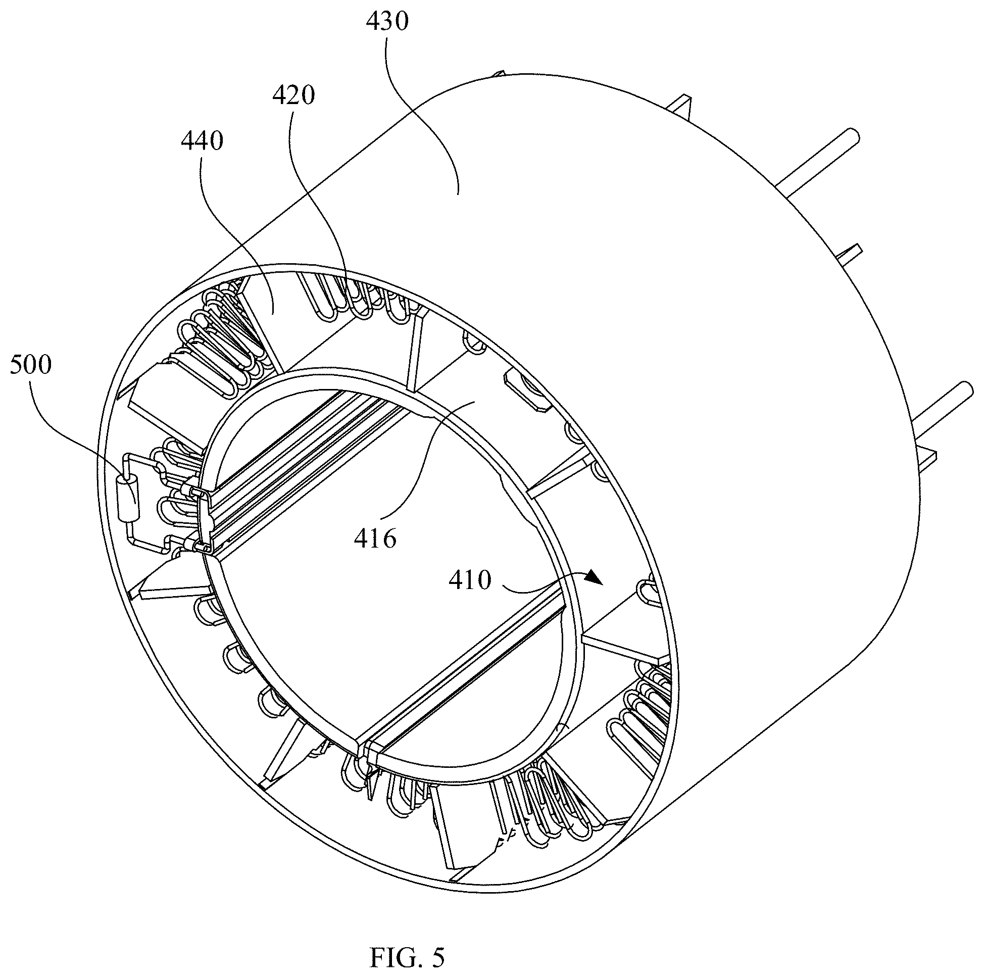
[0030] FIG. 5 is a local structural view of the hair drying apparatus according to another embodiment;
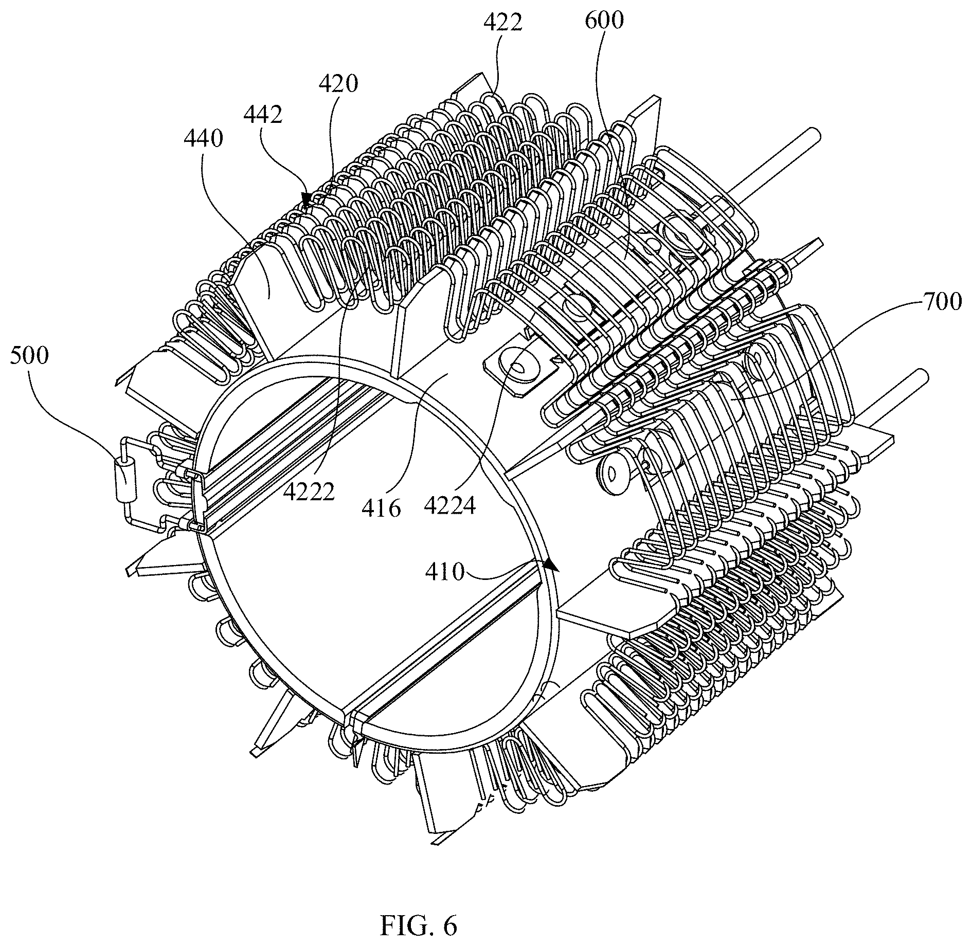
[0031] FIG. 6 is another local structural view of the hair drying apparatus shown in FIG. 5;
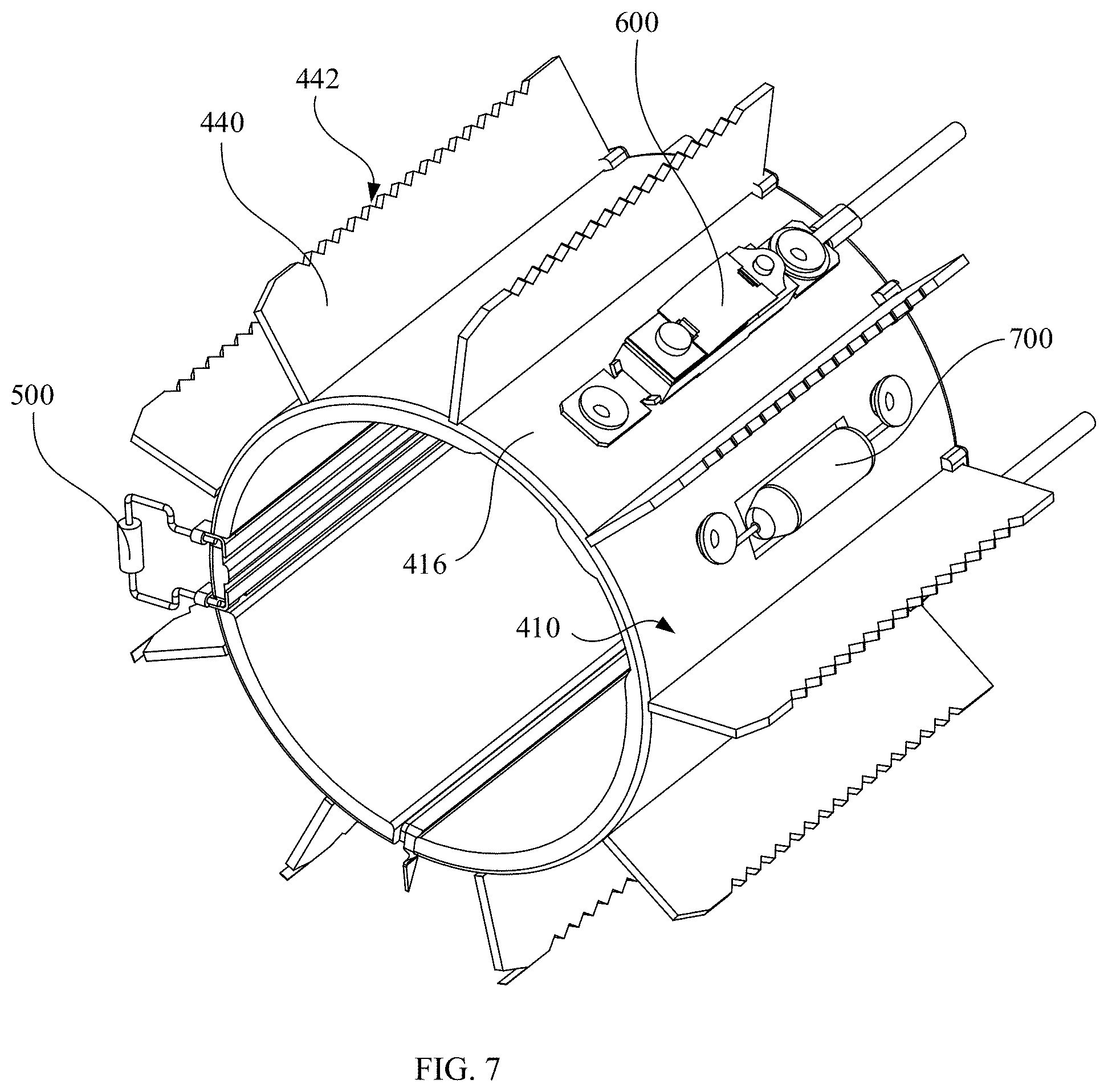
[0032] FIG. 7 is yet another local structural view of the hair drying apparatus shown in FIG. 5;
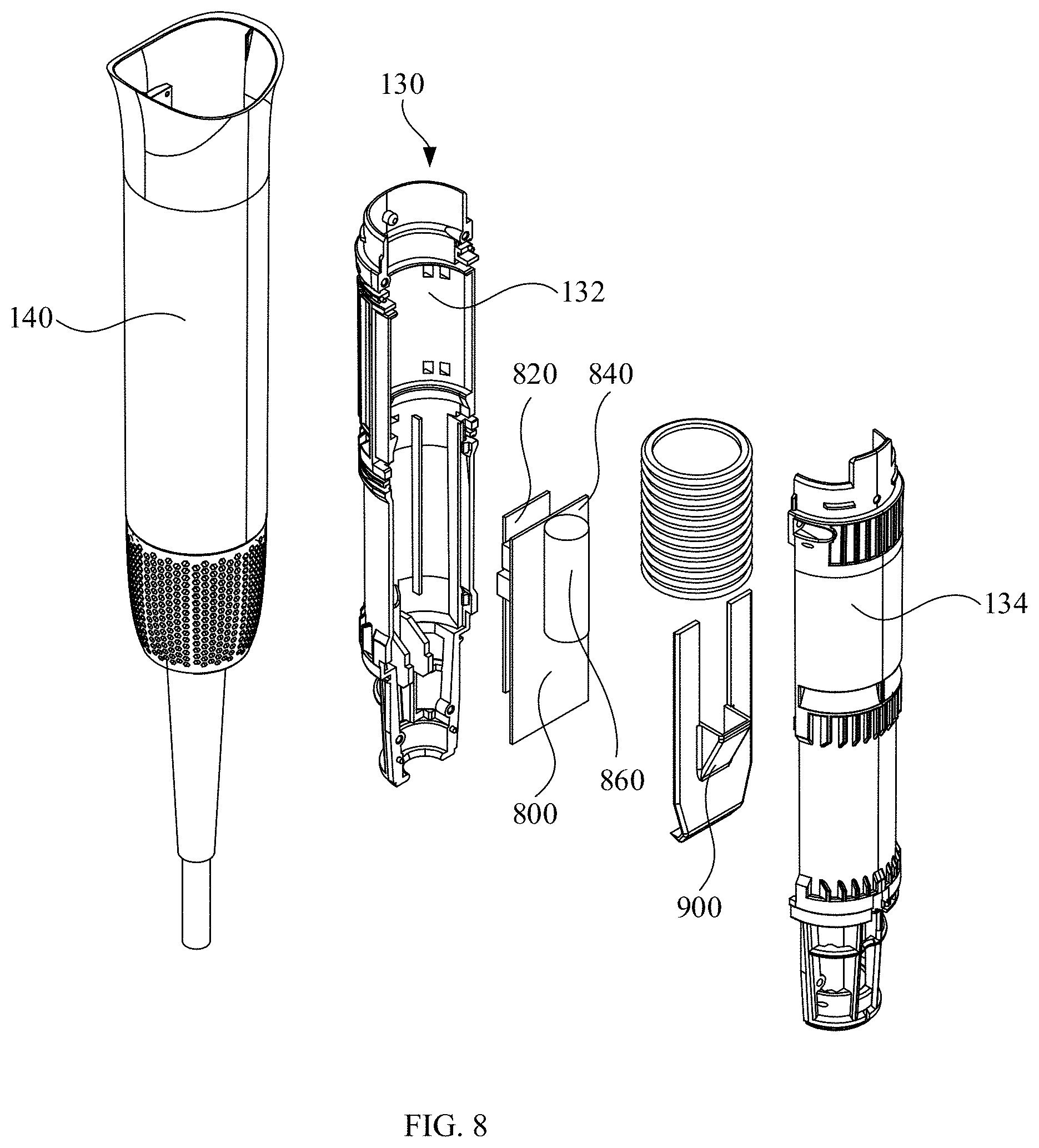
[0033] FIG. 8 is a local exploded view of the hair drying apparatus shown in FIG. 1;
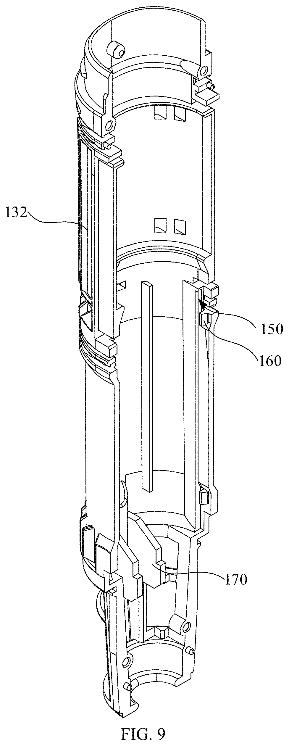
[0034] FIG. 9 is a structural view of a first inner case of the hair drying apparatus shown in FIG. 8;
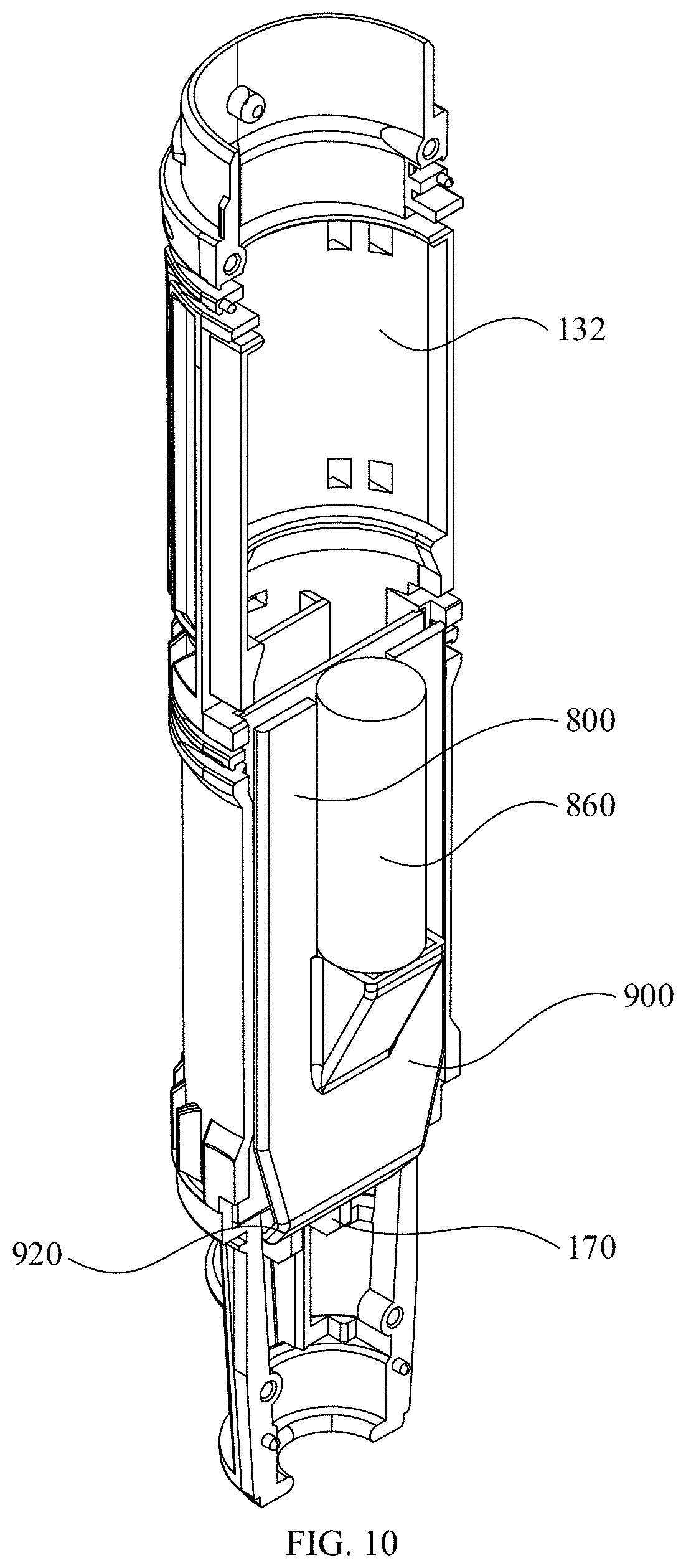
[0035] FIG. 10 is a structural view of the first inner case and a controller, which have been assembled, of the hair drying apparatus shown in FIG. 8;
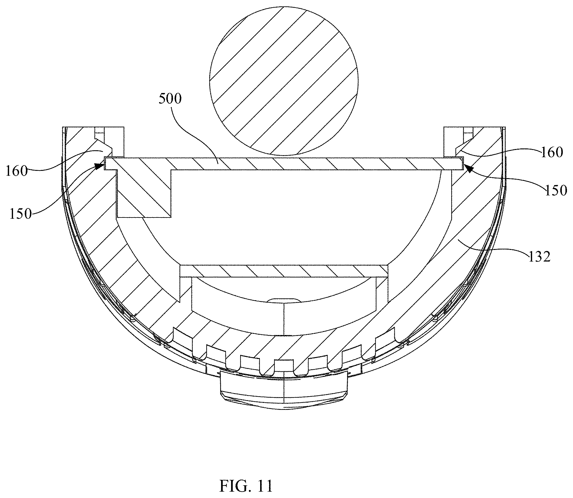
[0036] FIG. 11 is a cross-section view of the first inner case and the controller, which have been assembled, shown in FIG. 10; and
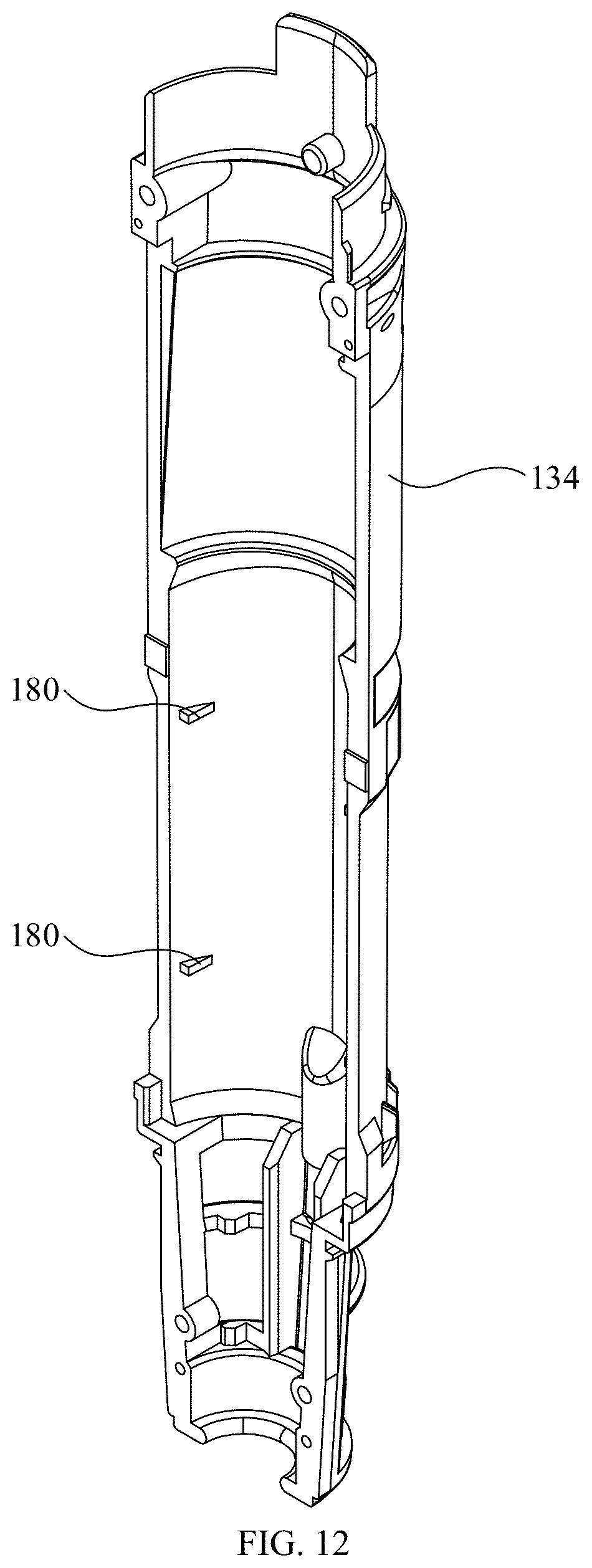
[0037] FIG. 12 is a structural view of a second inner case of the hair drying apparatus shown in FIG. 8.
DETAILED DESCRIPTION OF ILLUSTRATED EMBODIMENTS
[0038] In order to better understand the present disclosure, the application will be described more comprehensively in accompany with associated drawings. The drawings merely provide preferable embodiments. However, the present disclosure may be carried out in various alternative ways, but not exclusive to the embodiments described herein. Conversely, the embodiments provided in the specification aim for more thorough understanding of the present disclosure.
[0039] It should be understood that when an element is "fixed to" another element, the element may be directly located on the other element, alternatively, there may exist a third element therebetween. When an element is "connected to" another element, the element may be directly connected to the other element, alternatively, there may exist a third element therebetween. The terminologies such as "inner", "outer", "left", and "right" and the like used herein are merely for illustration, but not referring to exclusive implementations.
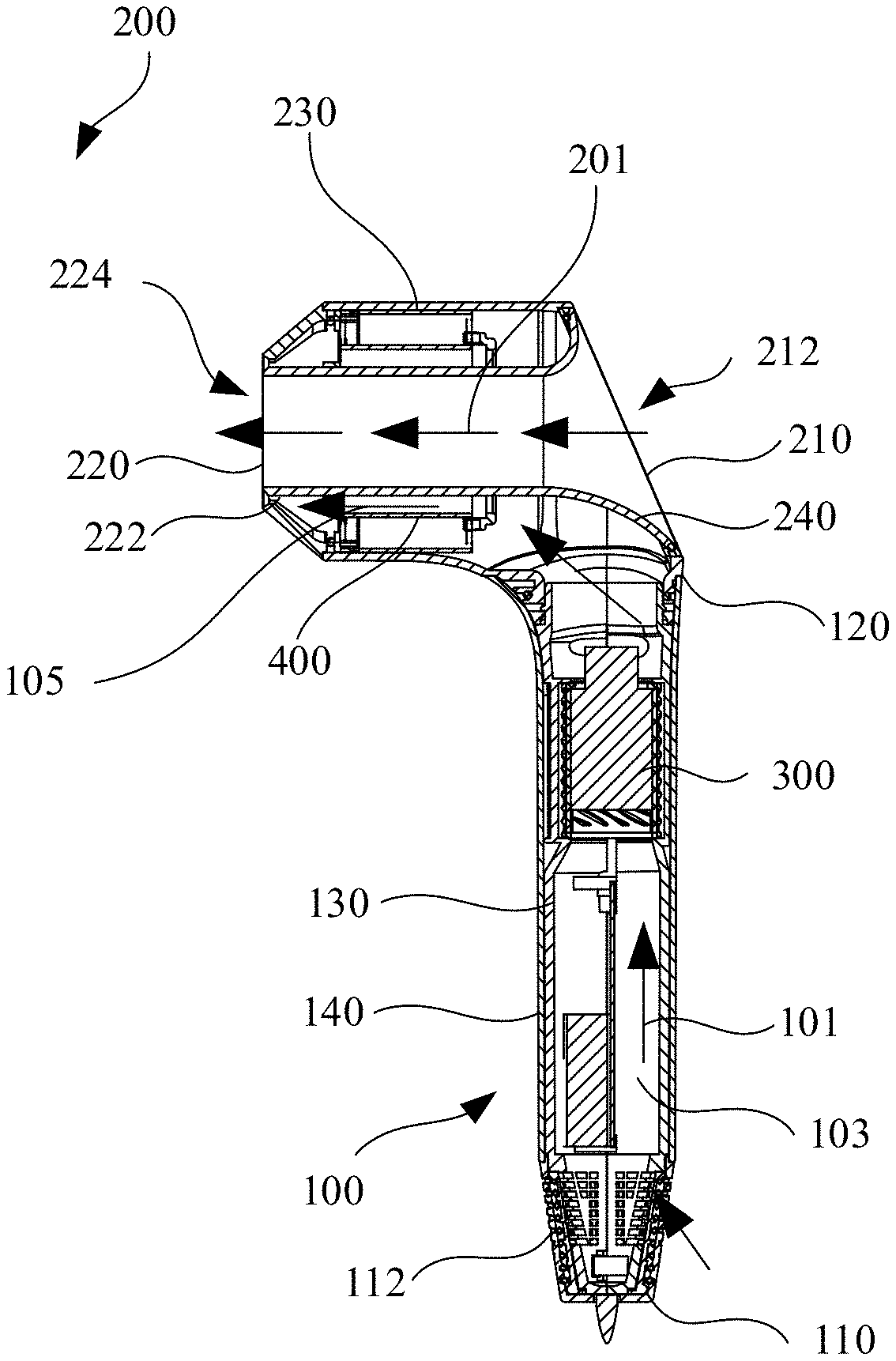
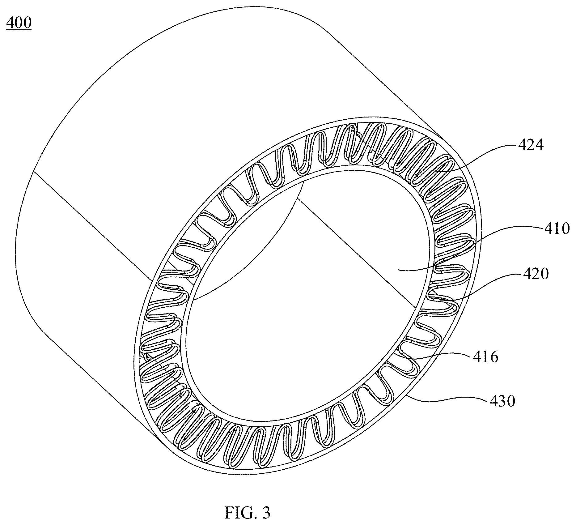
[0040] As shown in FIGS. 1-2, a hair drying apparatus 10 in one embodiment includes a handle 100 and a main body 200. The main body 200 is connected to the handle 100. The handle 100 and the main body 200 provide a first fluid channel 101 for fluid to flow through. The handle 100 includes a first fluid inlet 112. The main body 200 includes a first fluid outlet 222. The first fluid inlet 112 and the first fluid outlet 222 communicate with each other to form the first fluid channel 101. The first fluid inlet 112 and the first fluid outlet 222 are respectively designed for the fluid to flow into and out of the first fluid channel 100.
[0041] As shown in FIG. 2, in one embodiment, the handle 100 includes a first end 110 and a second end 120 arranged opposite to each other. The second end 120 of the handle 100 is connected to the main body 200. The first fluid inlet 112 is arranged at the first end 110 of the handle 100. The main body 200 includes a first end portion 210 and a second end portion 220 arranged opposite to each other. The first fluid outlet 222 is arranged at the second end portion 220 of the main body 200.
[0042] Furthermore, in the present embodiment, the first fluid channel 101 is not linear. The first fluid channel 101 includes a first section 103 and a second section 105 communicated with each other. An extension direction of the first section 103 is perpendicular to that of the second section 105. The first section 103 is located inside the handle 100. The second section 105 is located inside the main body 200. Therefore, the fluid flows along the first section 103 of the first fluid channel 101 through the handle 100, and then flows along the second section 105 of the first fluid channel 101 through the main body 200.
[0043] As shown in FIG. 2, in one embodiment, the hair drying apparatus 10 further includes a fan assembly 300. The fan assembly 300 is located inside the first fluid channel 101. In the present embodiment, the fan assembly 300 is located in the first section 103 of the first fluid channel 101. The fan assembly 300 is configured to suction the fluid, such that the fluid flows through the first fluid inlet 112 and into the first fluid channel 101.
[0044] As shown in FIG. 2, in one embodiment, the main body 200 further includes a first fluid inlet 212 and a second fluid outlet 224. The first fluid inlet 212 and the second fluid outlet 224 communicate with each other to form a second fluid channel 201. The second fluid inlet 212 and the second fluid outlet 224 are respectively designed for another fluid to flow into and out of the second fluid channel 201. In the present embodiment, the second fluid inlet 212 is located at the first end portion 210 of the main body 200. The second fluid outlet 224 is located at the second end portion 220 of the main body 200.
[0045] While the fan assembly 300 is running, the fan assembly 300 suctions a fluid, such that the fluid flows through the first fluid inlet 112 into the first fluid channel 101 and reaches the first fluid outlet 222. The fluid flowing through the main body 200 and out of the first fluid outlet 222 makes the other fluid at the second fluid inlet 212 be suctioned and drawn into the second fluid channel 201, and flows along the second fluid channel 201 towards the second fluid outlet 224. The other fluid that flows out through the second fluid outlet 224 and the fluid that flows out through the first fluid outlet 222 converge at the second end portion 220 of the main body 200, increasing fluid outflow rate of the hair drying apparatus 10.
[0046] As shown in FIG. 2, in one embodiment, the main body 200 includes a housing 230 and a tube body 240 passing through the housing 230. The second fluid channel 201 is defined by the tube body 240. The second fluid channel 201 extends within the tube body 240 from the second fluid inlet 212 to the second fluid outlet 224. The second section 105 of the first fluid channel 101 is defined by a gap between the tube body 240 and a sidewall of the housing 230. A cross section of the first fluid outlet 222 is of annular shape. The first fluid outlet 222 extends around the second fluid channel 201.
[0047] As shown in FIG. 2, in one embodiment, the hair drying apparatus 10 further includes a heater 400. The heater 400 is arranged inside the first fluid channel 101. In the present embodiment, the heater 400 is located in the second section 105 of the first fluid channel 101. The heater 300 extends around the tube body 240. The heater 400 is configured to heat up the fluid within the first fluid channel 101.
[0048] In the present embodiment, for illustrative purpose, an end of the heater 400 close to the first fluid outlet 222 is defined as a downstream end of the heater 400, the other end of the heater 400 distal to the first fluid outlet 222 defined as an upstream end of the heater 400. The fluid flows through the first fluid inlet 112 into the first fluid channel 101 and flows from the upstream end of the heater 400 through the downstream end of the heater 400, then flows along the first fluid channel 101 and reaches the first fluid outlet 222. Therefore, the heater 400 may selectively heat up the fluid in the first fluid channel 101 directly. Furthermore, the other fluid flowing through the second fluid channel 201 may also be heated up indirectly by the heater 400.
[0049] As shown in FIGS. 3-4, in one embodiment, the heater 400 includes an inner layer 410 and a heating element 420. The inner layer 410 is of annular structure. The inner layer 410 includes a first end wall 412, a second end wall 414, a third end wall 416 and a fourth end wall 418. The first end wall 412 is arranged opposite to the second end wall 414. In the present embodiment, the first end wall 412 is located at the downstream end of the heater 400. The second end wall 414 is located at the upstream end of the heater 400. The third end wall 416 is arranged opposite to the fourth end wall 418. The third end wall 416 and the fourth end wall 418 are connected between the first end wall 412 and the second end wall 414. The third end wall 416 and the fourth end wall 418 respectively extend around an axial direction of the inner layer 400. In one embodiment, the inner layer 410 is of hollow structure, the third end wall 416 forming an external sidewall of the inner layer 410, the fourth end wall forming an internal sidewall of the inner layer 410.
[0050] The heating element 420 is configured to heat up the fluid flowing therethrough. The heating element 420 is located at the third end wall 416 of the inner layer 410. Specifically, the heating element 420 is configured to generate thermal energy to heat up the fluid flowing through the heating element 420 upon electrified. The heating element 420 is single layered. The heating element 420 winds around the third end wall 416 of the inner layer 410.
[0051] In the heater 400, the heating element 420 is configured to be single layered such that overall size of the heater 400 is reduced, which lessens obstacles for the fluid to flow through the heater 400 and lowers flow loss of the fluid flowing through the heater 400. On the other hand, since space for the fluid to flow through the heater 400 is smaller, flow rate of the fluid is faster, which improves use performance of the heater substantially with features such as simple structure and small space occupation.
[0052] In one embodiment, the inner layer 410 is made of plastic material. In one embodiment, the plastic material is any one of polyphenyl ester, polybenzimidazole, polyboron diphenyl siloxane, polyphenylene sulfide, chlorinated polyether. Compared with mica material, plastic material possesses better plastic performance with greater hardness. By manufacturing the inner layer 410 of the heater 400 using the plastic material, the inner layer 410, as a heat insulation support structure of the heating elements 420, is easier to be set to alternative shapes and fixed to. Therefore, other structural elements are easier to be mounted relative to the inner layer 410 which acts as the thermal insulation support structure of the heating element 420, thereby substantially improving the bearing adaptability performance of the heater 400.
[0053] As shown in FIG. 3, in one embodiment, the heater 400 further includes an outer layer 430 for insulating the heating element 420. The outer layer 430 is of annular structure and extends around the heating element 420. The heating element 420 is located between the third end wall 416 of the inner layer 410 and the outer layer 430. The outer layer 430 may provide heat insulation for the heater 400 and structures for containing the heater 400. Furthermore, the outer layer 430 may also limit radial movement of the heating element 420 along the inner layer 410 to some extent. In the present embodiment, the outer layer 430 is made of insulation material. Preferably, the outer layer 430 is made of mica.
[0054] As shown in FIG. 4, furthermore, the outer layer 430 includes a fifth end wall 432, a sixth end wall 434, a seventh end wall 436 and an eighth end wall 438. The fifth end wall 432 is arranged opposite to the sixth end wall 434. In the present embodiment, the fifth end wall 432 is located at the downstream end of the heater 400. The sixth end wall 434 is located at the upstream end of the heater 400. The seventh end wall 436 is arranged opposite to the eighth end wall 438. The seventh end wall 436 and the eighth end wall 438 are connected between the fifth end wall 432 and the sixth end wall 434. The seventh end wall 436 and the eighth end wall 438 respectively extend around the heating element 420. The heating element 420 is located between a third end wall 416 of the inner layer 410 and the eighth end wall 438 of the outer layer 430.
[0055] As shown in FIG. 5, in one embodiment, the heater 400 further includes a supporter 440 for supporting the heating element 420. The supporter 440 is arranged on a third end wall 416 of the inner layer 410, and extends along a radial direction of the inner layer 410 towards the outer layer 430. In the present embodiment, the supporter 440 is made of insulation material. Preferably, the supporter 440 is made of mica.
[0056] As shown in FIGS. 6-7, furthermore, a plurality of supporters 440 are provided and arranged at intervals along a circumferential direction of the third end wall 416 so as to improve bearing stability of the heating element 420. In one embodiment, at least six supporters 440 are provided and arranged at intervals around a circumferential direction of the third end wall 416. Furthermore, the supporters 440 each provide a locating opening 442 for locating the heating element 420. The locating opening 442 is of zigzag shape. The heating element 420 is located within the locating opening 442 of each supporter 440.
[0057] In one embodiment, the heating element 420 is a metal wire which is constructed as zigzag or wave shape. The heating element 420 includes a plurality of turns of coil 422, one turn of coil being adjacent to another one. A plurality of locating openings 442 are provided and arranged along an identical line on the supporters 440 at intervals. The multiple turns of coil 422 of the heating element 420 are respectively located in the plurality of locating openings 442 of the supporters, thereby insulating each of the multiple turns of coil 422 of the heating element 420, and reducing limitation to the fluid flowing through the heater 400.
[0058] In one embodiment, a maximum distance from the coil 422 to the third end wall 416 is 6-9 mm, such that the coil 422 may be avoided from moving relative to the third end wall 416 without jeopardizing energy density of the coil 422, improving use performance of the heater 400.
[0059] In one embodiment, the coil 422 includes a first bending portion 4222 and a second bending portion 4224 connected to each other; the first bending portion 4222 and the second bending portion 4224 both wind around the third end wall 416, a length of the second bending portion 4224 along a circumference direction of the inner layer 410 being greater than that of the first bending portion 4222 along the circumference direction of the inner layer 410. By the structural configuration above, the space between the coil 422 and the third end wall 416 may be extended, thereby leaving space for other elements to mount between the coil 422 and the third end wall 416.
[0060] In one embodiment, the heating element 420 includes at least two separated heating units. The heating units are configured to generate thermal energy upon electrified. The configuration allows users to control each of the heating units independently. Therefore, for a low-temperature configuration, merely one of the heating units is needed. When one of the heating units is damaged, the heater 400 may still operate normally, which substantially improve use performance of the heater 400.
[0061] Furthermore, in the present embodiment, the heating element 420 includes two separated heating units. It is understood that in alternative embodiments, the number of the heating units may be three or more than three. Specific configuration may be selected properly based on actual condition. In the present embodiment, each heating unit includes a plurality of turns of coil 422, each turn being adjacent to another one.
[0062] As shown in FIGS. 6-7, in one embodiment, the hair drying apparatus 10 further includes a temperature detector 500. The temperature detector 500 is arranged inside the first fluid channel 101. The temperature detector 500 includes but not limited to a thermistor. The temperature detector 500 is configured to detect temperature of the fluid within the first fluid channel 101. When the first fluid inlet 112 or the first fluid outlet 222 of the first fluid channel 101, inside which the heater 400 is located, is blocked, since fluid flowing around the heating element 420 is limited, the thermal energy cannot be carried away from the heating element 420 by the fluid timely, resulting in overheating of the heating element 420. The temperature detector 500 may detect temperature of the fluid inside the first fluid channel 101 timely. Users may detect whether the heating element 420 is overheated based on detection result, thereby heating the fluid in the first fluid channel 101 controlled by the heater 400 with precise control, and making sure that the hair drying apparatus 10 be used properly.
[0063] Furthermore, in the present embodiment, the temperature detector 500 is arranged at the downstream end of the heater 400. Specifically, the temperature detector 500 is arranged on the first end wall 412 of the inner layer 410. The temperature detector 500 is configured to detect temperature of the fluid between the heater 400 and the first fluid outlet 222. Since temperature of the fluid between the heater 400 and the first fluid outlet 222 is closer to the temperature of actual outflow fluid of the hair drying apparatus 10, the temperature detector 500 may use the temperature of the fluid between the heater 400 and the first fluid outlet 222 as a reference standard for temperature detection by arranging the temperature detector 500 at the downstream end of the heater 400, thereby heating the fluid in the first fluid channel 101 controlled by the heater 400 with precise control.
[0064] As shown in FIGS. 6-7, in one embodiment, the hair drying apparatus 10 further includes a first over-temperature protector 600. The first over-temperature protector 600 is arranged inside the first fluid channel 101 and electrically connected to the heating element 420. The first over-temperature protector 600 includes but not limited to an elastic metal sheet. The first over-temperature protector 600 is configured to disconnect access of power source to the heating element 420 once the temperature of the fluid in the first fluid channel 101 reaches a first preset threshold, and to connect the power source to the heating element 420 once the temperature of the fluid in the first fluid channel 101 falls below the first preset threshold.
[0065] The first over-temperature protector 600 is normally not affected by the fluid flowing therethrough, however, when the first fluid inlet 112 or the first fluid outlet 122 of the first fluid channel 101 is blocked, the temperature of the fluid inside the first fluid channel will rise. When the temperature of the fluid in the first fluid channel 101 reaches the first preset threshold, the first over-temperature protector 600 disconnects access of power source to the heating element 420; when the temperature of the fluid in the first fluid channel 101 falls below the first preset threshold, the first over-temperature protector 600 reconnects the power source to the heating element 420, thereby heating the fluid in the first fluid channel 101 controlled by the heater 400 effectively, and making sure that the hair drying apparatus 10 possesses safe use performance.
[0066] In the present embodiment, the first over-temperature protector 600 is arranged between the third end wall 416 of the inner layer 410 and the heating element 420. Specifically, the first over-temperature protector 600 is embedded in the third end wall 416 of the inner layer 410. Since temperature of the fluid inside the heating element 420 is relatively even, by arranging the first over-temperature protector 600 inside the heating element 420, the first over-temperature protector 600 may utilize the temperature of the fluid inside the heating element 420 as a temperature standard for determining whether disconnecting or connecting access of the power source to the heating element 420, thereby heating up the fluid inside the first fluid channel 101 controlled by the heater 400 with precise control.
[0067] As shown in FIGS. 6-7, in one embodiment, the hair drying apparatus 10 further includes a second over-temperature protector 700. The second over-temperature protector 700 is located in the first fluid channel 101, and electrically connected to the heating element 420. The second over-temperature protector 700 includes but not limited to a thermofuse. The second over-temperature protector 700 is configured to disconnect access of power source to the heating element 420 once the temperature of the fluid in the first fluid channel 101 reaches a second preset threshold.
[0068] Furthermore, the second preset threshold is higher than the first preset threshold. When the first over-temperature protector 600 does not work and the temperature of the fluid inside the first fluid channel 101 reaches the second preset threshold, the second over-temperature protector 700 may disconnect access of power source to the heating element 420, thereby controlling the heater 400 to heat up the fluid inside the first fluid channel 101 more effectively, ensuring safety performance of the hair drying apparatus 10.
[0069] In the present embodiment, the second over-temperature protector 700 is embedded in the third end wall 416 of the inner layer 410, and within the heating element 420. Similar to the configuration of the first over-temperature protector 600, arranging the second over-temperature protector 700 inside the heating element 420 allows the second over-temperature protector 700 to use the temperature of the fluid inside the first fluid channel 101 as a temperature standard for determining whether disconnecting or connecting the access of the power source to the heating element 420, thereby heating up the fluid inside the first fluid channel 101 controlled by the heater 400 with precise control.
[0070] As shown in FIG. 8, in one embodiment, the hair drying apparatus 10 further includes a controller 800. The controller 800 is arranged in the first fluid channel 101, and within the handle 100. Since the controller 800 is located within the first fluid channel 101 and within the handle 100, while the fluid is flowing through the first fluid channel 101 within the handle 100, the fluid may carry away thermal energy generated by the controller 800 timely for heat dissipation of the controller 800, avoiding arranging additional radiators for heating dissipation of the controller 800 within the handle 100 or the main body 200, reducing the number of elements of the hair drying apparatus 10, and hence reducing production cost.
[0071] It should not that in the present embodiment, the controller 800 is electrically connected to the fan assembly 300 and the heater 400. The controller 800 may control heating temperature of the heater 400 and rotation rate of the fan assembly 300. Furthermore, the controller 800 is electrically connected to the temperature detector 500. The controller 800 may control the heating temperature of the heater 400 based on detection result of the temperature detector 500.
[0072] As shown in FIGS. 9-11, in one embodiment, a locating slot 150 is arranged in the inner sidewall of the handle 100. The controller 800 is contained in the locating slot 150. Two opposite inner sidewalls of the locating slot 150 are provided with clips 160. The clips 160 are configured to press against two ends of the controller 800 to fix the controller 800 to a bottom wall of the locating slot 150.
[0073] Furthermore, two opposite inner sidewalls of the locating slot 150 are respectively provided with a plurality of clips 160 for improving mounting stability of the controller 800 inside the locating slot 150. In the present embodiment, two clips 160 are respectively arrange on each of the two opposite sidewalls of the locating slot 150. Four clips 160 respectively press against four corners of the controller 800. It should be understood that, the number of the clips 160 arranged on each of the two opposite sidewalls of the locating slot 150 may be three or more than three. Specific configuration may be selected properly based on actual condition.
[0074] As shown in FIG. 8, in one embodiment, the controller 800 includes a first controller 820 and a second controller 840. The first controller 820 is electrically connected to the second controller 840. In the present embodiment, the controller 800 is of separated structure, such that the structure of the controller 800 is more compact, thereby making full use of the space within the handle 100, reducing size of the controller 800 along one single direction, hence reducing the size of the hair drying apparatus 100. Furthermore, if one of the first controller 820 and the second controller 840 is damaged, merely the damaged one requires to be amended, which reduces maintenance cost substantially. Furthermore, in the present embodiment, the first controller 820 is arranged opposite to the second controller 840.
[0075] It should be understood that in one embodiment, the controller 800 further includes a connector. The first controller 820 is connected to the second controller 840 through the connector. In one embodiment, the connector is a pin header. In one embodiment, the connector includes a pin header and a female head matched with the pin header in plug-in mode. The first controller 820 is fixed relative to the second controller 840 through the connector, such that when the controller 800 and the handle 100 is assembled, merely one of the first controller 820 and the second controller 840 requires to be fixed to the handle 100.
[0076] As shown in FIG. 8, it is worth mentioning that in the present embodiment, the first controller 820 and the second controller 840 are both cuboid, which lowers production complexity and improves production efficiency. In other embodiments, the first controller 820 and the second controller 840 may be of other shapes, such as with cross-section shapes such as circular and elliptical.
[0077] As shown in FIG. 8, in one embodiment, the handle 100 includes an inner case 130. The inner case 130 is connected to the main body 200. The inner case 130 includes a first inner case 132 and a second inner case 134 clipped to each other. The first inner case 134 and the second inner case 134 are clipped together to form the first fluid channel 101 of the handle 100, which is the first section 103 of the first fluid channel 101. The locating slot 150 is located within an inner sidewall of one of the first inner case 132 and the second inner case 134. An extension direction of the locating slot 150 is parallel to that of the first section 103 of the first fluid channel 101. In one embodiment, the handle 100 further includes an outer case 140. The outer case 140 sheaths around the inner case 130 and connects with the main body 200.
[0078] As shown in FIGS. 8-10, in one embodiment, the hair drying apparatus 10 further includes a protection cover 900. The protection cover 900 covers the controller 800. The configuration of the protection cover 900 may protect the controller 800 to some extent, such that the fluid within the first fluid channel 101 of the handler 100 flows around the controller 800. On the other hand, when one or more elements of the controller 800 are damaged, the protection cover 800 may act as a baffle, such that the damaged elements of the controller 800 may be blocked from entering the first fluid channel 101 of the main body 200.
[0079] As shown in FIG. 10, in one embodiment, one end of the protection cover 900 is arranged with a bevel 920. An angle exists between the bevel 920 and an extension direction of the handle 100. The configuration performs a guiding function for the fluid to flow within the first fluid channel 101 and through the protection cover 900, thereby reducing turbulence within the first fluid channel 101 for perpendicular change of flowing direction while the fluid is flowing through the protection cover 900, thereby reducing noise.
[0080] As shown in FIGS. 9-10, in the present embodiment, the locating slot 150 is arranged within the inner sidewall of the first inner case 132. An inner sidewall of the first inner case 132 is further provided with a stopper 170. The controller 800 includes a capacitor 860 embossing and extending towards the second inner case 134. Specifically, the capacitor 860 is arranged on a side of the second controller 840 away from the first controller 820. The protection cover 900 is stopped and limited between the stopper 170 and the capacitor 860.
[0081] As shown in FIG. 12, furthermore, an inner sidewall of the second inner case 134 is provided with a crimping element 180. The crimping element 180 may crimp the protection cover 900 such that the protection cover 900 is fixed to the controller 800. Specifically, there exist a plurality of crimping elements 180. The plurality of crimping elements 180 are arranged on the inner sidewall of the second inner case 134 in an array arrangement, thereby improving crimping stability of the protection cover 900 relative to the controller 800.
[0082] Technical features described in the above embodiments may be combined in any way. For brief description, not all possible combinations of the technical features in the above embodiments are described. However, as long as there is no contradiction therebetween, the combinations should be considered as falling into the scope of this manual.
[0083] The above embodiments are merely for illustrating several embodiments of the present invention, and the description thereof is more specific and detailed. However, this should not be deemed as constructing limitation of the scope of the invention. It should be noted that numerous variations and modifications may be made by those skilled in the art without departing from the spirit and scope of the invention. Therefore, the scope of the invention should be determined by the appended claims.
* * * * *
D00000
D00001
D00002
D00003
D00004
D00005
D00006
D00007
D00008
D00009
D00010
D00011
D00012
XML
uspto.report is an independent third-party trademark research tool that is not affiliated, endorsed, or sponsored by the United States Patent and Trademark Office (USPTO) or any other governmental organization. The information provided by uspto.report is based on publicly available data at the time of writing and is intended for informational purposes only.
While we strive to provide accurate and up-to-date information, we do not guarantee the accuracy, completeness, reliability, or suitability of the information displayed on this site. The use of this site is at your own risk. Any reliance you place on such information is therefore strictly at your own risk.
All official trademark data, including owner information, should be verified by visiting the official USPTO website at www.uspto.gov. This site is not intended to replace professional legal advice and should not be used as a substitute for consulting with a legal professional who is knowledgeable about trademark law.