Adjustable Fit Ring
YEP; Mau Koung
U.S. patent application number 16/175529 was filed with the patent office on 2020-04-30 for adjustable fit ring. This patent application is currently assigned to New Atlantic Assets Limited. The applicant listed for this patent is New Atlantic Assets Limited. Invention is credited to Mau Koung YEP.
| Application Number | 20200128929 16/175529 |
| Document ID | / |
| Family ID | 70327846 |
| Filed Date | 2020-04-30 |


View All Diagrams
| United States Patent Application | 20200128929 |
| Kind Code | A1 |
| YEP; Mau Koung | April 30, 2020 |
Adjustable Fit Ring
Abstract
An adjustable fit ring includes a main ring and a plurality of adjusters. The main ring has a ring inner peripheral surface, a ring outer peripheral surface, a front surface, a rear surface, a through cavity formed as a space surrounded by the ring inner peripheral surface, and a slot formed on the ring inner peripheral surface. The plurality of adjusters are received in the slot of the ring inner peripheral surface. The adjuster has an adjuster inner peripheral surface, an adjuster outer peripheral surface, and a resilient element installed on the adjuster outer peripheral surface to push against an inner wall of the ring outer peripheral surface, the adjuster being connected to the main ring to move between a resting position and a pressed-in position.
| Inventors: | YEP; Mau Koung; (Hong Kong, HK) | ||||||||||
| Applicant: |
|
||||||||||
|---|---|---|---|---|---|---|---|---|---|---|---|
| Assignee: | New Atlantic Assets Limited |
||||||||||
| Family ID: | 70327846 | ||||||||||
| Appl. No.: | 16/175529 | ||||||||||
| Filed: | October 30, 2018 |
| Current U.S. Class: | 1/1 |
| Current CPC Class: | A44C 9/0046 20130101; A44C 9/02 20130101 |
| International Class: | A44C 9/02 20060101 A44C009/02 |
Claims
1. An adjustable fit ring, comprising: a main ring having a ring inner peripheral surface, a ring outer peripheral surface, a front surface, a rear surface, a through cavity formed as a space surrounded by said ring inner peripheral surface, and a slot formed on said ring inner peripheral surface; and a plurality of adjusters received in said slot of said ring inner peripheral surface having an adjuster inner peripheral surface, an adjuster outer peripheral surface, and a resilient element installed on said adjuster outer peripheral surface to push against an inner wall of said ring outer peripheral surface, said plurality of adjusters being connected to said main ring to move between a pressed-in position and a resting position; wherein in said pressed-in position, said plurality of adjuster are fully received within said slot of said ring inner peripheral surface, wherein in said resting position, said resilient element is uncompressed and retains said plurality of adjusters to extend beyond said ring inner peripheral surface.
2. The adjustable fit ring, as recited in claim 1, wherein said plurality of adjusters are provided in pairs placed symmetrically from a middle axis of said main ring.
3. The adjustable fit ring, as recited in claim 2, wherein said plurality of adjusters are pivotally connected to said main ring.
4. The adjustable fit ring, as recited in claim 3, wherein said adjuster outer peripheral surface of said plurality of adjusters comprises a groove and an insert housing for receiving said resilient element.
5. The adjustable fit ring, as recited in claim 4, wherein said resilient element comprises an attaching portion and a pushing portion.
6. The adjustable fit ring, as recited in claim 5, wherein said resilient element is formed by said attaching portion joining with said pushing portion by a single piece of metal forming a V-shape.
7. The adjustable fit ring, as recited in claim 5, wherein said resilient element is formed by said attaching portion joining with said pushing portion by a single piece of metal wire forming a loop coil.
8. The adjustable fit ring, as recited in claim 5, wherein said attaching portion has the same curvature as said adjuster.
9. The adjustable fit ring, as recited in claim 1, wherein said slot is provided in an upper portion of said ring inner peripheral surface.
10. The adjustable fit ring, as recited in claim 2, wherein said slot is provided in an upper portion of said ring inner peripheral surface.
11. The adjustable fit ring, as recited in claim 3, wherein said slot is provided in an upper portion of said ring inner peripheral surface.
12. The adjustable fit ring, as recited in claim 4, wherein said slot is provided in an upper portion of said ring inner peripheral surface.
13. The adjustable fit ring, as recited in claim 5, wherein said slot is provided in an upper portion of said ring inner peripheral surface.
14. The adjustable fit ring, as recited in claim 1, wherein said slot is provided in a lower portion of said ring inner peripheral surface.
15. The adjustable fit ring, as recited in claim 2, wherein said slot is provided in a lower portion of said ring inner peripheral surface.
16. The adjustable fit ring, as recited in claim 3, wherein said slot is provided in a lower portion of said ring inner peripheral surface.
17. The adjustable fit ring, as recited in claim 4, wherein said slot is provided in a lower portion of said ring inner peripheral surface.
18. The adjustable fit ring, as recited in claim 5, wherein said slot is provided in a lower portion of said ring inner peripheral surface.
19. An adjustable fit ring, comprising: a main ring having a ring inner peripheral surface, a ring outer peripheral surface, a front surface, a rear surface, a through cavity formed as a space surrounded by said ring inner peripheral surface, and a slot formed on said ring inner peripheral surface; and a secondary adjuster received in said slot of said ring inner peripheral surface having an adjuster inner peripheral surface, an adjuster outer peripheral surface, and a resilient element installed on said adjuster outer peripheral surface to push against an inner wall of said ring outer peripheral surface, said secondary adjuster being connected to said main ring to move between a pressed-in position and a resting position; wherein in said pressed-in position, said secondary adjuster is fully received within said slot of said ring inner peripheral surface, wherein in said resting position, said resilient element is uncompressed and retains said secondary adjuster to extend beyond said ring inner peripheral surface.
20. The adjustable fit ring, as recited in claim 19, wherein said slot is provided in an upper portion of said ring inner peripheral surface.
Description
BACKGROUND OF THE PRESENT INVENTION
Field of Invention
[0001] The present invention relates to a ring, and more particularly to a jewel ring with an adjustable fit feature such that users with different finger sizes may wear the ring fittedly when putting it on the first time without any prior measurement or adjustment.
Description of Related Arts
[0002] Conventional jewel rings only come in one size. If the ring does not fit the user, the ring will need to be readjusted for fitting. There are many disadvantages for an unfit ring. For example, if the ring is too tight, it may be uncomfortable for the user to wear. If the ring may be too loose, then it is easy to lose the ring. In addition, if the ring is too loose, the display featured jewel (typically on top of the ring) may move around loosely. Thus, it is very important to have the correct fitting for the ring. Conventional way for adjusting the size of the ring is by stretching the ring to enlarge it. There are other conventional design jewel rings which allow user to customize or adjust the size of the ring according to their needs. However, these designs are often complicated in structure and require the user to manipulate some kind of mechanism for changing the inner ring size.
[0003] As one may see from the above, there are problems with these conventional design rings. Thus, there is a need to invent a jewel ring with an adjustable fit feature such that the user may enjoy wearing a fitted ring without any prior configurations.
SUMMARY OF THE PRESENT INVENTION
[0004] The present invention provides an adjustable fit ring which a user may the ring fittedly when putting it on the first time without any prior measurement or adjustment.
[0005] In one aspect of the present invention, it provides an adjustable fit ring, comprising:
[0006] a main ring having a ring inner peripheral surface, a ring outer peripheral surface, a front surface, a rear surface, a through cavity formed as a space surrounded by the ring inner peripheral surface, and a slot formed on the ring inner peripheral surface; and
[0007] plurality of adjusters received in the slot of the ring inner peripheral surface having an adjuster inner peripheral surface, an adjuster outer peripheral surface, and a resilient element installed on the adjuster outer peripheral surface to push against an inner wall of the ring outer peripheral surface, the plurality of adjusters being connected to the main ring to move between a pressed-in position and a resting position;
[0008] wherein in the pressed-in position, the plurality of adjusters are fully received within the slot of the ring inner peripheral surface, wherein in the resting position, the resilient element is uncompressed and retains the plurality of adjusters to extend beyond the ring inner peripheral surface.
[0009] In another aspect of the present invention, it provides an adjustable fit ring, comprising:
[0010] a main ring having a ring inner peripheral surface, a ring outer peripheral surface, a front surface, a rear surface, a through cavity formed as a space surrounded by the ring inner peripheral surface, and a slot formed on the ring inner peripheral surface; and
[0011] a secondary adjuster received in the slot of the ring inner peripheral surface having an adjuster inner peripheral surface, an adjuster outer peripheral surface, and a resilient element installed on the adjuster outer peripheral surface to push against an inner wall of the ring outer peripheral surface, the secondary adjusters being connected to the main ring to move between a resting position and a pressed-in position.
[0012] wherein in the pressed-in position, the secondary adjuster is fully received within the slot of the ring inner peripheral surface, wherein in the resting position, the resilient element is uncompressed and retains the secondary adjuster to extend beyond the ring inner peripheral surface.
[0013] This summary presented above is provided merely to introduce certain concepts and not to identify any key or essential features of the claimed subject matter.
BRIEF DESCRIPTION OF THE DRAWINGS
[0014] FIG. 1 is a perspective view of the adjustable fit ring according to the first embodiment of the present invention.
[0015] FIG. 2 is a side view of the main ring according to the first embodiment of the present invention illustrating the location of the slot.
[0016] FIG. 3 is another perspective view of the adjustable fit ring according to the first embodiment of the present invention illustrating the location of the slot.
[0017] FIGS. 4A and 4B are perspective views of the adjuster according to the first embodiment of the present invention.
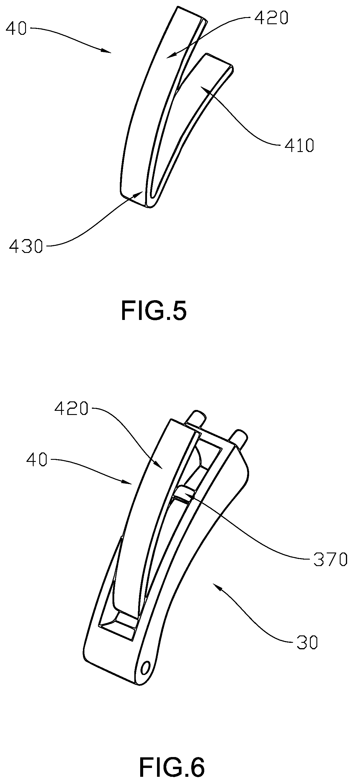
[0018] FIG. 5 is a perspective view of the resilient element according to the first embodiment of the present invention.
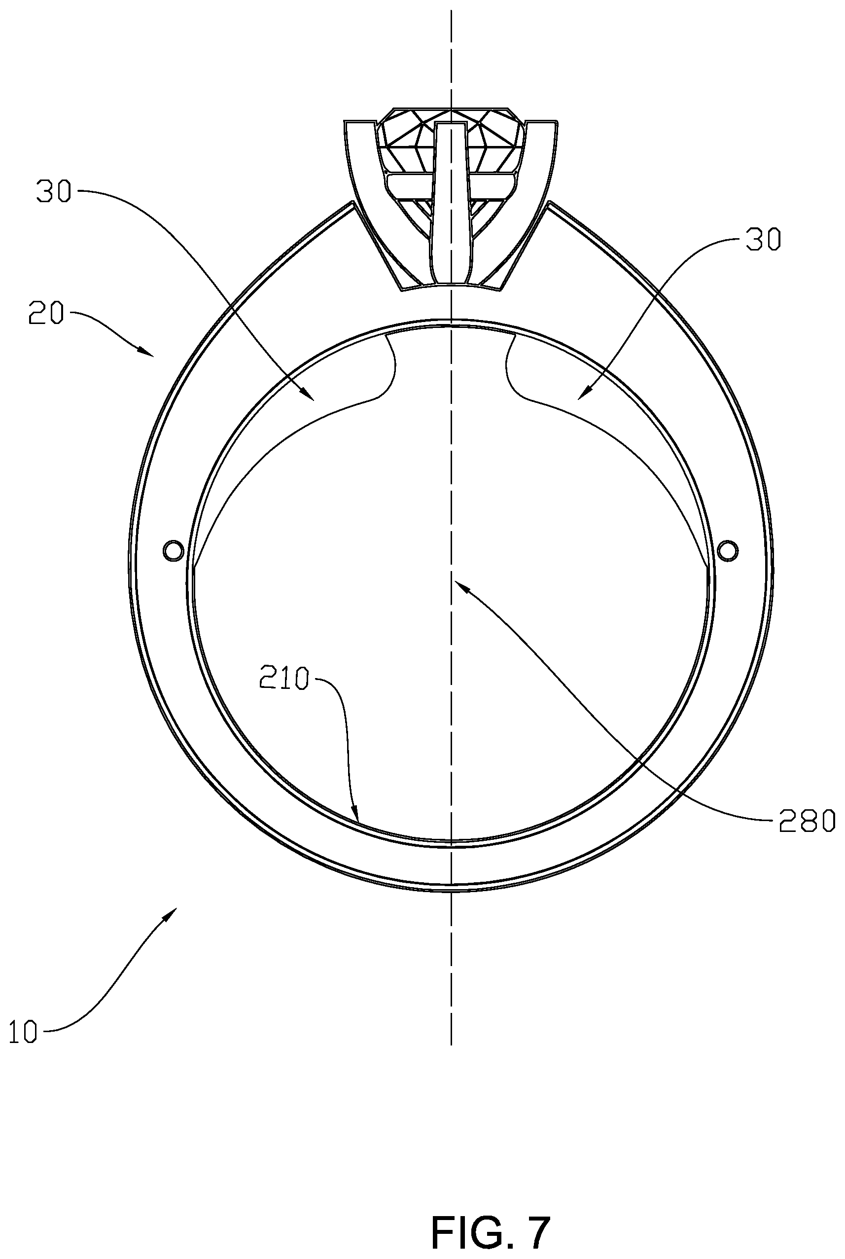
[0019] FIG. 6 is a perspective view of the resilient element and the adjuster according to the first embodiment of the present invention.
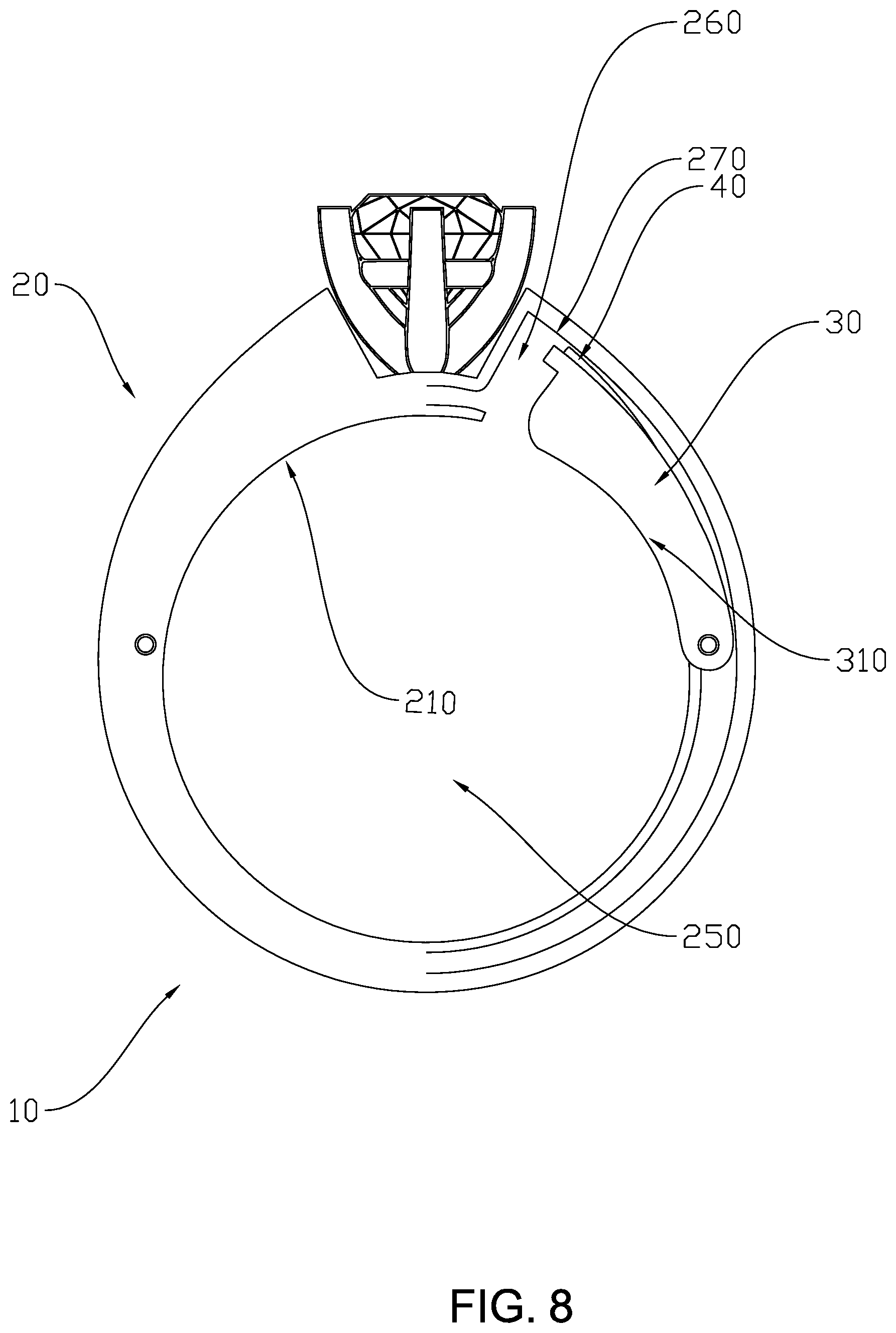
[0020] FIG. 7 is a side view of the adjustable fit ring according to the first embodiment of the present invention.
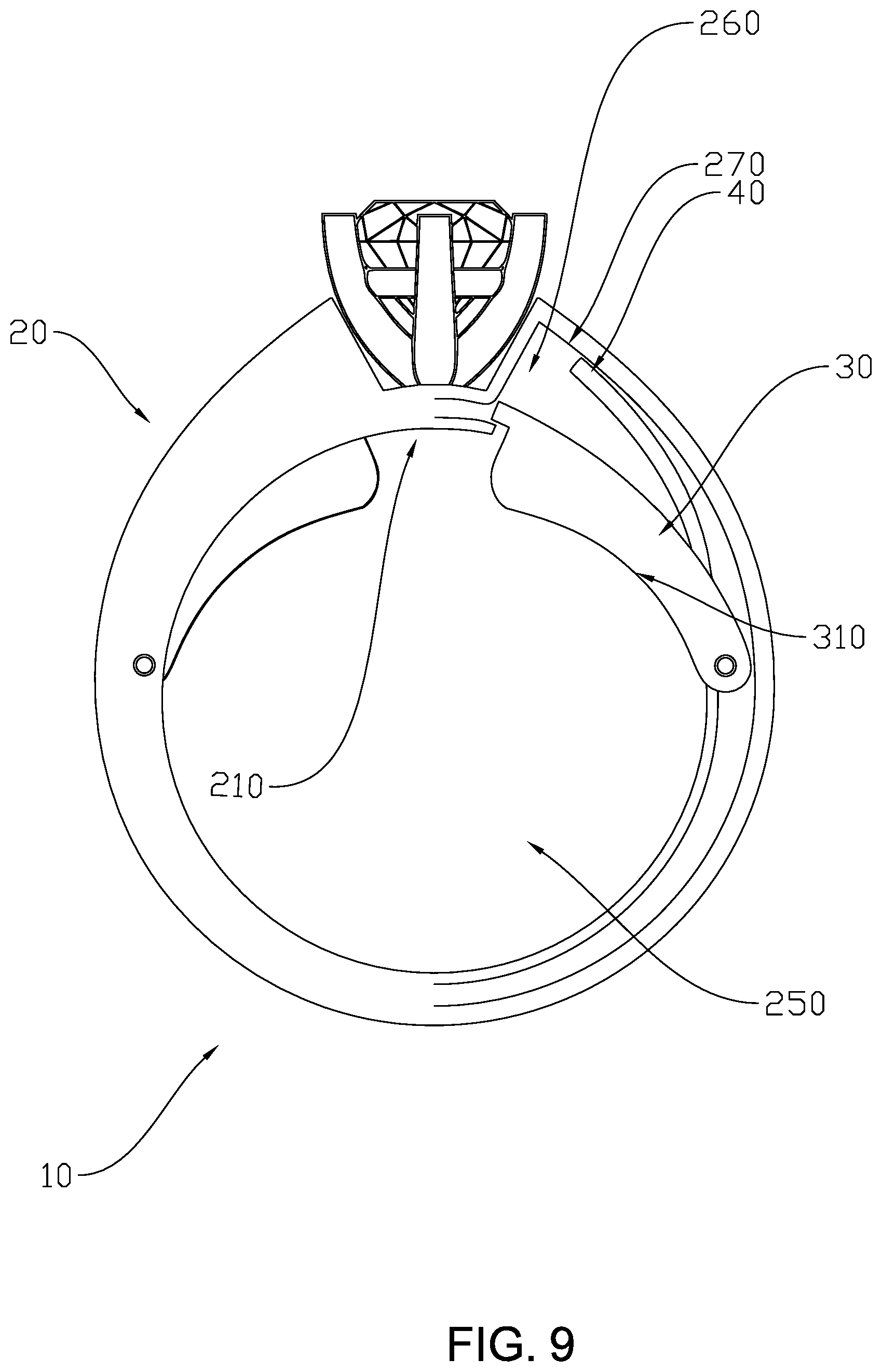
[0021] FIG. 8 is a partial see through side view of the adjustable fit ring according to the first embodiment of the present invention illustrating the adjuster and the resilient element in a pressed-in position.
[0022] FIG. 9 is a partial see through side view of the adjustable fit ring according to the first embodiment of the present invention illustrating the adjuster and the resilient element in a resting position.
[0023] FIG. 10 is a side view of the adjustable fit ring according to an alternative of the present invention.
[0024] FIG. 11 is a perspective view of the resilient element according to an alternative of the present invention.
[0025] FIG. 12 is a perspective view of the adjuster with the resilient element inserted according to an alternative of the present invention.
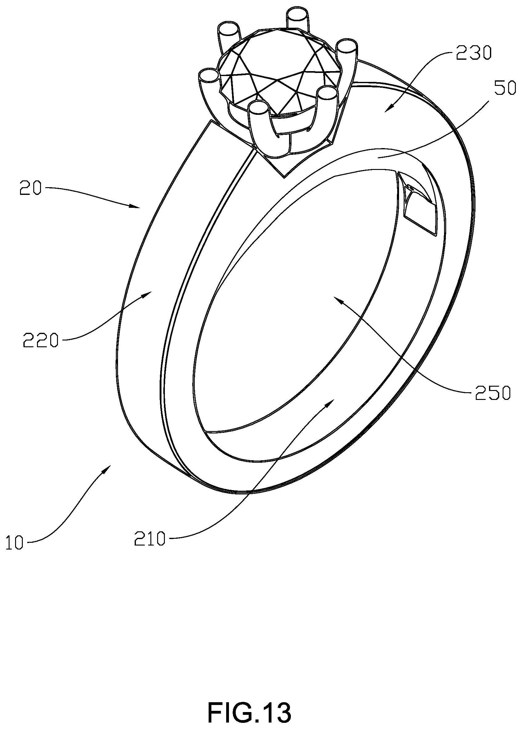
[0026] FIG. 13 is a perspective view of an adjustable fit ring according to the second embodiment of the present invention.
[0027] FIG. 14 is a side view of the main ring according to the second embodiment of the present invention illustrating the location of the slot.
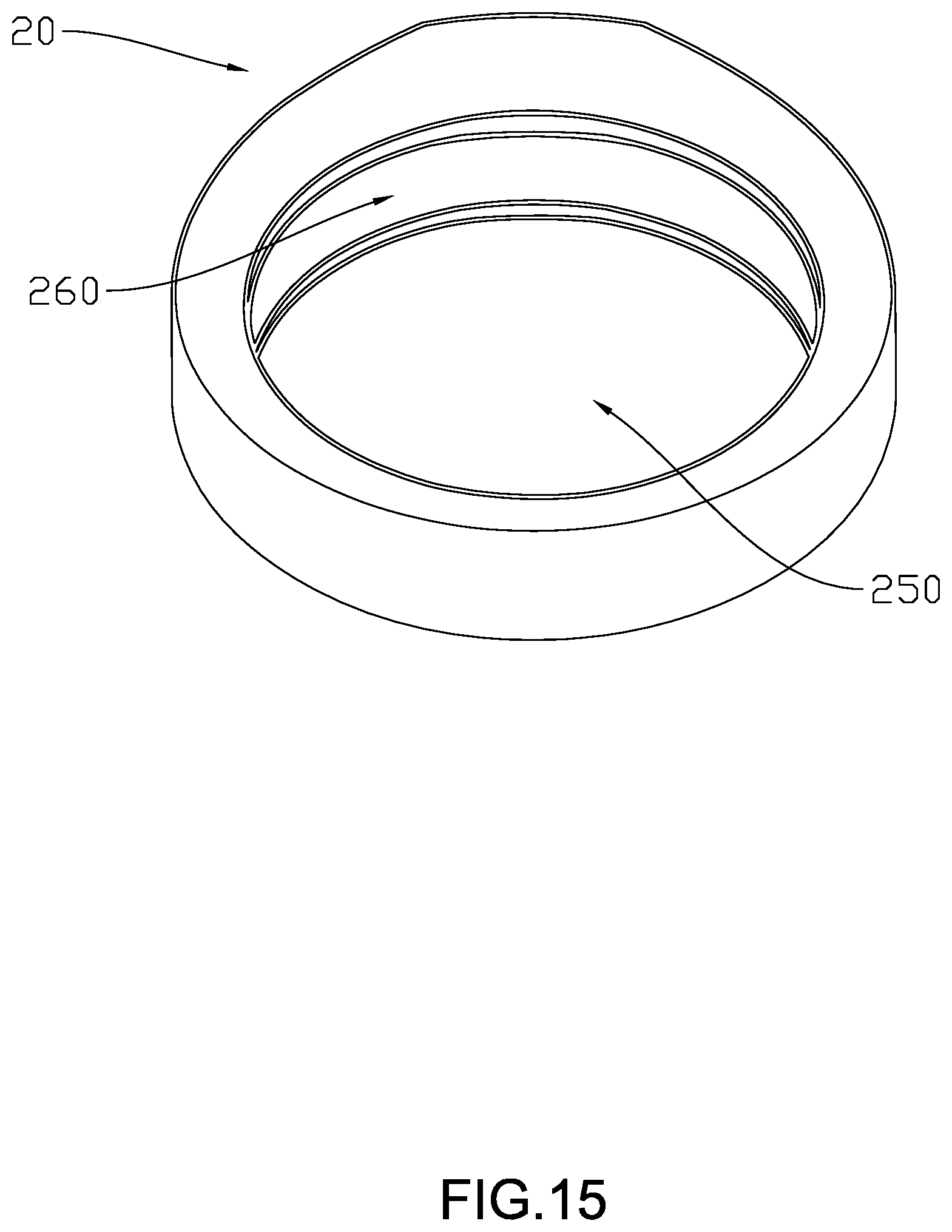
[0028] FIG. 15 is another perspective view of the adjustable fit ring according to the second embodiment of the present invention illustrating the location of the slot.
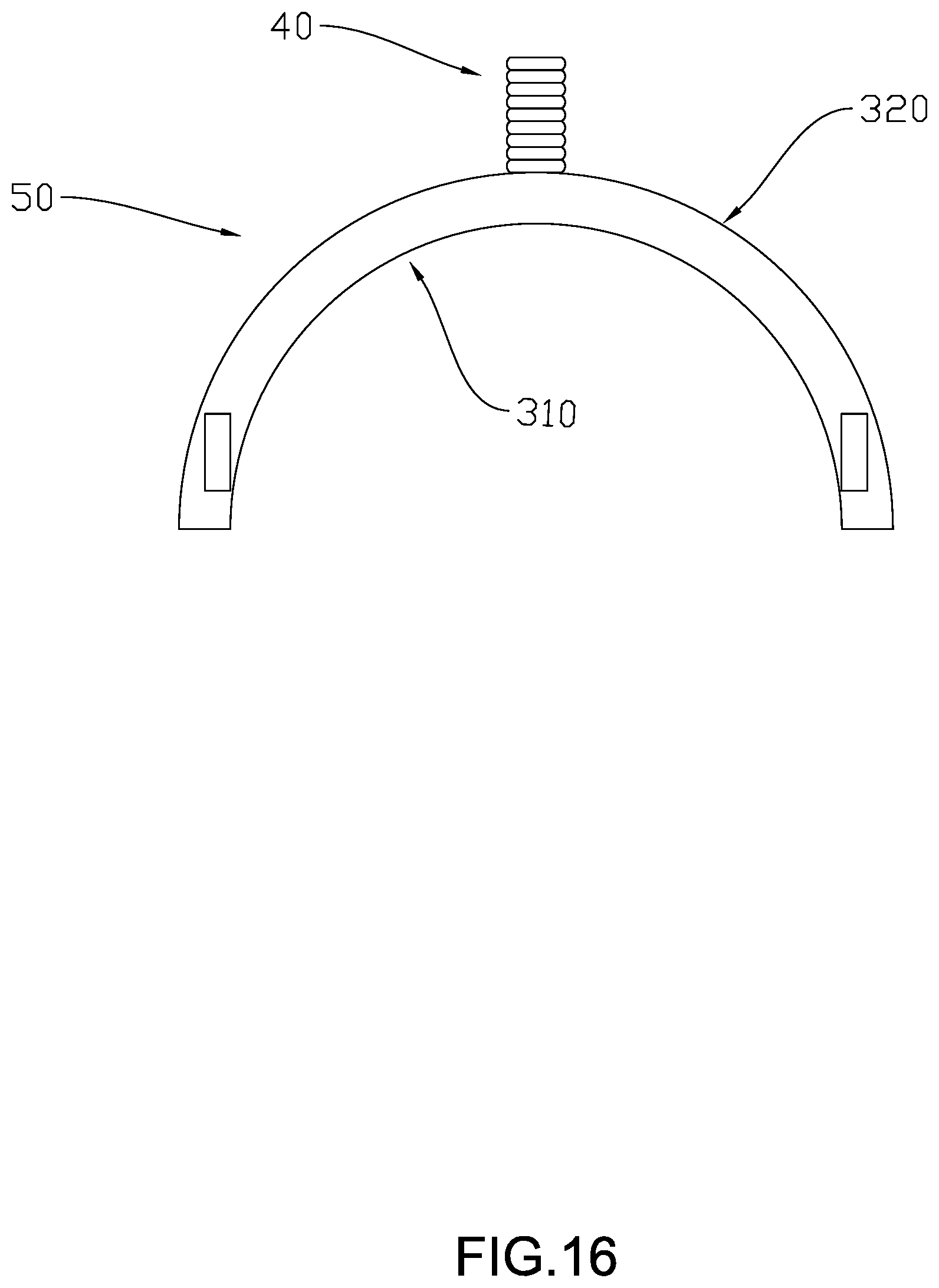
[0029] FIG. 16 is a side view of the secondary adjuster and the resilient element according to the second embodiment of the present invention.
[0030] FIG. 17 is a side view of the adjustable fit ring according to the second embodiment of the present invention illustrating the adjuster and the resilient element in a pressed-in position.
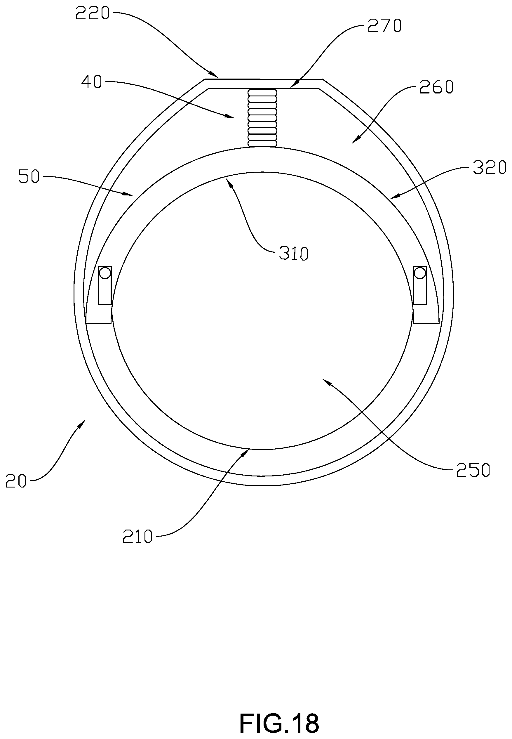
[0031] FIG. 18 is a side view of the adjustable fit ring according to the second embodiment of the present invention illustrating the adjuster and the resilient element in a resting position.
DETAILED DESCRIPTION OF THE PREFERRED EMBODIMENT
[0032] The following detailed description of the preferred embodiment is the preferred mode of carrying out the invention. The description is not to be taken in any limiting sense. It is presented for the purpose of illustrating the general principles of the present invention.
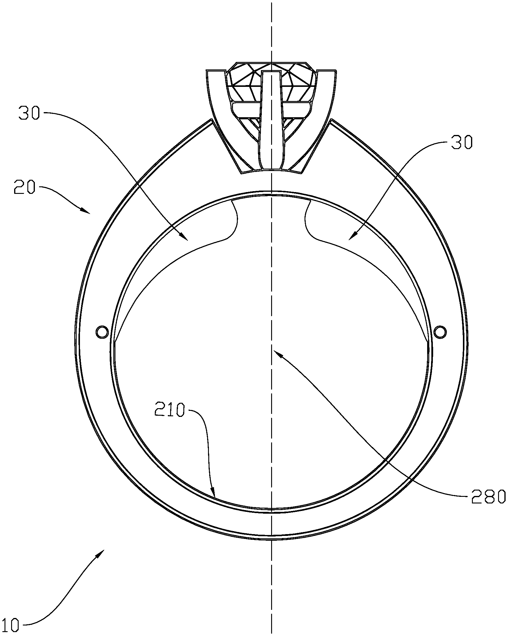
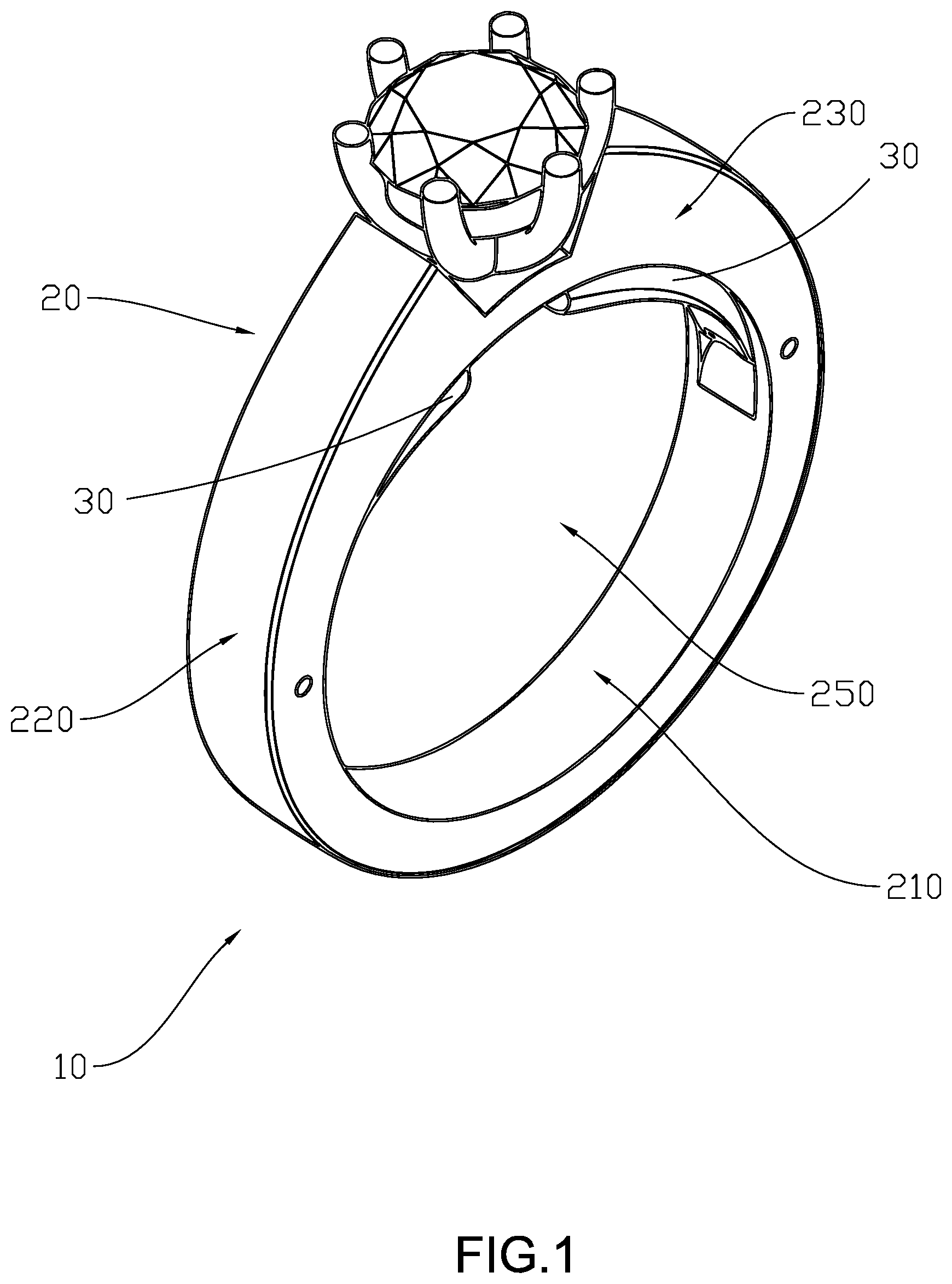
[0033] Referring to FIG. 1 of the drawings, the adjustable fit ring 10 according to the first embodiment of the present invention is illustrated. Broadly, the adjustable fit ring 10 may comprise a main ring 20, a plurality of adjusters 30, and a resilient element 40. The main ring 20 may have a ring inner peripheral surface 210, a ring outer peripheral surface 220, a front surface 230, a rear surface 240, and a through cavity 250 formed as a space surrounded by the ring inner peripheral surface 210. The rear surface 240 is just on the opposite side of the front surface 230.
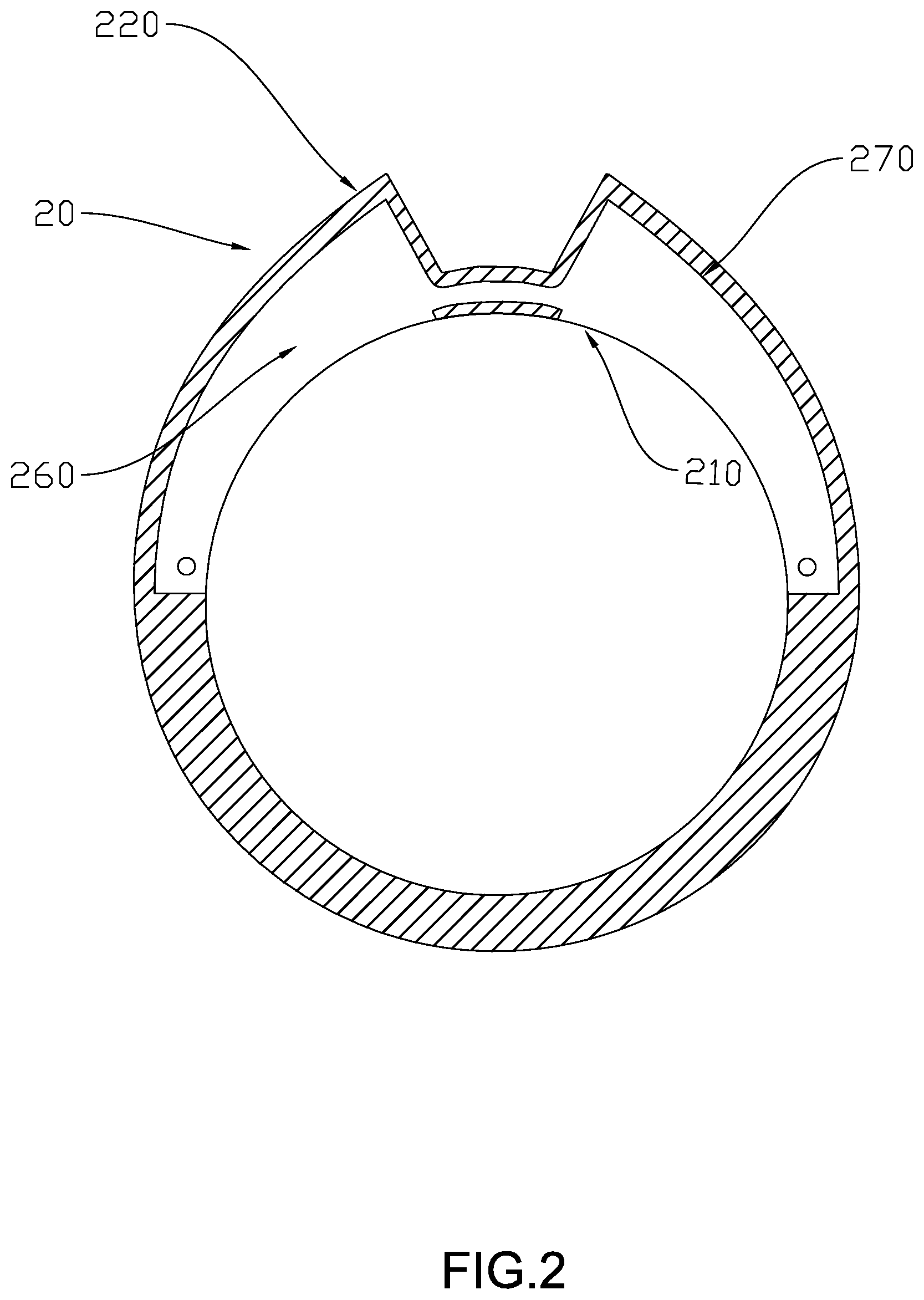
[0034] Referring to FIG. 2 of the drawings, a cross sectional side view of the main ring 20 according to the first embodiment of the present invention is illustrated. The ring inner peripheral surface 210 has a slot 260 located at an upper portion of the ring inner peripheral surface 210. The slot 260 is provided inside the ring inner peripheral surface 210 such that an inner wall surface 270 of the ring outer peripheral surface 220 can be exposed.
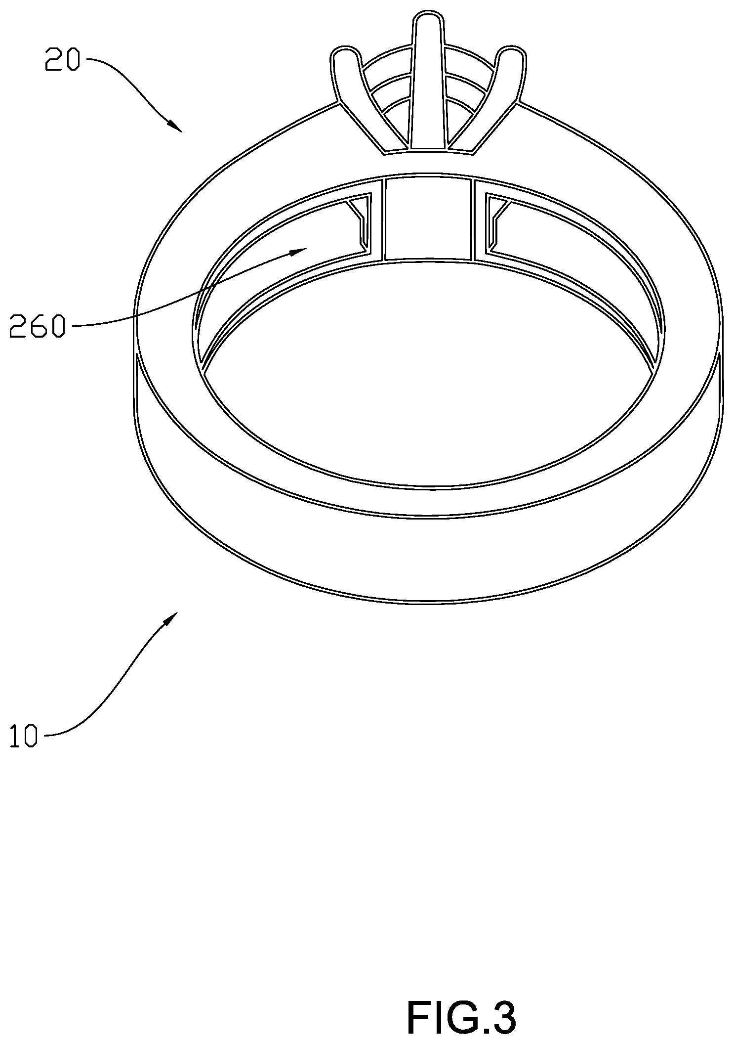
[0035] Referring to FIG. 3 of the drawings, another perspective view of the adjustable fit ring 10 is illustrated. It can be seen that the slot 260 provides an empty space area for receiving the adjuster 30.
[0036] Referring to FIG. 4A and FIG. 4B of the drawings, two perspective views of the adjuster 30 are illustrated. The adjuster 30 comprises an adjuster inner peripheral surface 310, and an adjuster outer peripheral surface 320. The adjuster outer peripheral surface 320 further comprises a groove 350 and an insert housing 370 for receiving the resilient element 40.
[0037] Referring to FIG. 5 of the drawings, a perspective view of the resilient element 40 according to the first embodiment of the present invention is illustrated. The resilient element 40 further comprises an attaching portion 410 and a pushing portion 420. The attaching portion 410 joins with the pushing portion 420 which is formed by a single piece of metal forming a V-shape 430 which may bend when the attaching portion 410 or the pushing portion 420 are pressed. Referring to FIG. 6 of the drawings, the attaching portion 410 of the resilient element 40 is inserted inside the insert housing 370 of the adjuster 30. According to this embodiment, the insert housing 370 is rectangular in shape for receiving a rectangular cross sectional shaped resilient element 40.
[0038] Referring to FIG. 7-9 of the drawings, side views of the adjustable fit ring 10 according to the first embodiment of the present invention are illustrated. According to the first embodiment of the present invention, the plurality of adjusters 30 are installed to received inside the slot 260 of the ring inner peripheral surface 210. The plurality of adjusters 30 are placed symmetrically along a middle axis 280 of the main ring 20 such that the support on the finger are balanced and is more stable. The plurality of adjusters 30 are capable to pivotally move between a pressed-in position and a resting position. An end of the adjuster 30 is pivotally connected to the main ring 20 by a simple slot and bolt connection. The pushing portion 420 of the resilient element 40 presses against the inner wall surface 270. In a pressed-in position, according to FIG. 8 of the drawings, the resilient element 40 is compressed which pivotally moves the adjuster 30 such that the adjuster 30 is fully received within the slot 260 of the ring inner peripheral surface 210. The attaching portion 410 has the same curvature of the adjuster 30 such that the compressed resilient element 40 can be fittedly and fully received inside the groove 350 of the adjuster 30. In a resting position, the uncompressed resilient element 40 naturally provides a steady force from the pushing portion 420 onto the inner wall surface 270 to retain the adjuster 30 to extend beyond the ring inner peripheral surface 210 as shown in FIG. 9 of the drawings.
[0039] As shown in the first embodiment of the present invention, the plurality of adjusters 30 are capable to move between the pressed-in position and the resting position. If a user inserts his/her finger into the through cavity 250, the resilient element 40 will compress according to the finger size and retain the position of the plurality of adjusters 30 by pressing the adjuster inner peripheral surface 310 downwardly in close contact against the user's finger. When the adjuster inner peripheral surface 310 is pressing against the user's finger, it will help prevent the adjustable fit ring 10 from moving which can help to always display the ornament on the ring.
[0040] FIG. 10 of the drawings illustrates a side view of the adjustable fit ring 10 according to an alternative of the present invention. According to this alternative, the slot 260 is located at a lower portion of the ring inner peripheral surface 210. Accordingly, the plurality of adjusters 30 are also installed to receive inside the slot 260 at the lower portion of the ring inner peripheral surface 210. Aside from the location of the slots 260, the structure and the operation of this alternative is the same as the first embodiment of the present invention.
[0041] FIG. 11 and FIG. 12 of the drawings illustrate another alternative of the present invention. FIG. 11 of the drawings displays a perspective view of the resilient element 40. According to this alternative, the resilient element 40 has a circular cross sectional shape and is formed by a single piece of metal wire forming a loop coil 440 as shown in the FIG. 11. The attaching portion 410 of the resilient element 40 is inserted inside the insert housing 370 of the adjuster 30. According to this alternative, the insert housing 370 is circular in shape for receiving a circular cross sectional shaped resilient element 40. FIG. 12 of the drawings illustrates a perspective view of the resilient element 40 inserted inside the adjuster 30.
[0042] Referring to FIG. 13 of the drawings, the adjustable fit ring 10 according to the second embodiment of the present invention is illustrated. Broadly, the adjustable fit ring 10 may comprise the main ring 20, a secondary adjuster 50, and the resilient element 40. The main ring 20 may have the ring inner peripheral surface 210, the ring outer peripheral surface 220, the front surface 230, the rear surface 240, and the through cavity 250 formed as a space surrounded by the ring inner peripheral surface 210. The rear surface 240 is just on the opposite side of the front surface 230. The surfaces of the main ring 20 are the same as illustrated above from the first embodiment of the present invention.
[0043] Referring to FIG. 14 of the drawings, a cross section side view of the main ring 20 according to the second embodiment of the present invention is illustrated. The ring inner peripheral surface 210 has the slot 260 located at an upper portion of the ring inner peripheral surface 210. The slot 260 is provided inside the ring inner peripheral surface 210 such that the inner wall surface 270 of the ring outer peripheral surface 220 can be exposed.
[0044] Referring to FIG. 15 of the drawings, another perspective view of the adjustable fit ring 10 is illustrated. It can be seen that the slot 260 provides an empty space area for receiving the secondary adjuster 50.
[0045] Referring to FIG. 16-18 of the drawings, the side view of the secondary adjuster 50 and the resilient element 40 is illustrated. According to the second embodiment of the present invention, the secondary adjuster 50 is capable to travel in an up and down motion to move between a pressed-in position and a resting position. The secondary adjuster 50 is received inside the slot 260 of the ring inner peripheral surface 210. A simple glide mechanism is used to allow the secondary adjuster 50 to move. The secondary adjuster 50 has the adjuster inner peripheral surface 310 and the adjuster outer peripheral surface 320. According to the second embodiment of the present invention, the resilient element 40 is a simple spring which can be compressed. One end of the resilient element 40 is connected to the adjuster outer peripheral surface 320 of the secondary adjuster 50. Another end of the resilient element 40 is connected to the inner wall surface 270. In the pressed-in position, according to FIG. 17 of the drawings, the resilient element 40 is compressed which moves the secondary adjuster 50 upward through the glide mechanism such that the secondary adjuster 50 is fully received within the slot 260 of the ring inner peripheral surface 210. In the resting position, the uncompressed resilient element 40 naturally provides a steady force onto the inner wall surface 270 to retain the secondary adjuster 50 to extend beyond the ring inner peripheral surface 210 as shown in FIG. 18 of the drawings
[0046] As shown in the second embodiment of the present invention, the secondary adjuster 50 is capable to move between the resting position and the pressed-in position. If a user inserts his/her finger into the through cavity 250, the resilient element 40 will compress according to the finger size and retain the position of the secondary adjuster 50 by pressing the adjuster inner peripheral surface 310 downwardly in close contact against the user's finger. When the adjuster inner peripheral surface 310 is pressing against the user's finger, it will help to prevent the adjustable fit ring 10 from moving which can help to always display the ornament on the ring.
[0047] The present invention, while illustrated and described in terms of different preferred embodiments, is not limited to the particular description contained in this specification. Additional alternative or equivalent components could also be used to practice the present invention.
* * * * *
D00000
D00001
D00002
D00003
D00004
D00005
D00006
D00007
D00008
D00009
D00010
D00011
D00012

D00013
D00014
D00015

D00016
XML
uspto.report is an independent third-party trademark research tool that is not affiliated, endorsed, or sponsored by the United States Patent and Trademark Office (USPTO) or any other governmental organization. The information provided by uspto.report is based on publicly available data at the time of writing and is intended for informational purposes only.
While we strive to provide accurate and up-to-date information, we do not guarantee the accuracy, completeness, reliability, or suitability of the information displayed on this site. The use of this site is at your own risk. Any reliance you place on such information is therefore strictly at your own risk.
All official trademark data, including owner information, should be verified by visiting the official USPTO website at www.uspto.gov. This site is not intended to replace professional legal advice and should not be used as a substitute for consulting with a legal professional who is knowledgeable about trademark law.