Footwear With Active Gripping Outsole
Loverin; Marc R.
U.S. patent application number 16/176283 was filed with the patent office on 2020-04-30 for footwear with active gripping outsole. The applicant listed for this patent is Wolverine Outdoors, Inc.. Invention is credited to Marc R. Loverin.
| Application Number | 20200128913 16/176283 |
| Document ID | / |
| Family ID | 66349322 |
| Filed Date | 2020-04-30 |
| United States Patent Application | 20200128913 |
| Kind Code | A1 |
| Loverin; Marc R. | April 30, 2020 |
FOOTWEAR WITH ACTIVE GRIPPING OUTSOLE
Abstract
A footwear construction is provided including a sole assembly having one or more active gripping pods that collapse upon themselves to grip underfoot surfaces and terrain. The gripping pods can include a generally centrally located actuator lug that engages a ground surface and collapses upward and optionally into the sole assembly, and while so doing, pulls one or more adjacent lug rings toward it along corresponding arcuate paths. The collapse and pull in of the lug rings causes those elements to grip the ground surface with a predetermined force.
| Inventors: | Loverin; Marc R.; (Scituate, MA) | ||||||||||
| Applicant: |
|
||||||||||
|---|---|---|---|---|---|---|---|---|---|---|---|
| Family ID: | 66349322 | ||||||||||
| Appl. No.: | 16/176283 | ||||||||||
| Filed: | October 31, 2018 |
| Current U.S. Class: | 1/1 |
| Current CPC Class: | A43C 15/02 20130101; A43C 15/168 20130101; A43B 13/26 20130101; A43B 13/04 20130101; A43C 15/16 20130101; A43B 3/02 20130101; A43B 13/184 20130101 |
| International Class: | A43B 13/26 20060101 A43B013/26; A43B 13/04 20060101 A43B013/04; A43C 15/02 20060101 A43C015/02; A43C 15/16 20060101 A43C015/16 |
Claims
1. An article of footwear comprising: an upper; a sole assembly joined with the upper, the sole assembly including a first gripping pod, the first gripping pod comprising: a first central axis; a first actuator lug generally aligned with the first central axis, the first actuator lug including an actuator lug ground contacting surface defining a periphery and an exterior actuator lug wall extending upwardly from the actuator lug ground contacting surface; and a first lug ring that surrounds the first actuator lug and that is disposed radially outward from the exterior actuator lug wall, the first lug ring including a lug ring interior edge and a lug ring interior wall that face generally toward the exterior actuator lug wall, and a lug ring ground contacting surface; wherein the first gripping pod includes a first collapse compartment defined in the sole assembly above the first actuator lug and the first lug ring; wherein the first gripping pod is operable in an extended mode when the first gripping pod is not under a compressive force due to a wearer's weight, and in a gripping mode when the first gripping pod is under the compressive force, wherein in the gripping mode, the first actuator lug and the first lug ring collapse at least partially into the first collapse compartment, with the first lug ring moving toward the first central axis of the first gripping pod in the gripping mode, wherein the lug ring interior edge is disposed above the ground contacting surface of the first actuator lug such that a part of the lug ring ground contacting surface is above the ground contacting surface of the first actuator lug in the gripping mode, whereby a ground surface material is grabbed between the lug ring interior wall and the actuator lug exterior wall to improve traction of the footwear relative to the ground surface material.
2. The article of footwear of claim 1, comprising: a second gripping pod distal from the first gripping pod, the second gripping pod comprising: a second central axis; a second actuator lug aligned with the second central axis; a second lug ring that surrounds the second actuator lug; wherein the second gripping pod includes a second collapse compartment defined in the sole assembly above the second actuator lug and the second lug ring; wherein the second gripping pod is operable in an extended mode and in a gripping mode, wherein in the gripping mode, the second actuator lug and the second lug ring collapse at least partially into the second collapse compartment, with the second lug ring moving toward the second central axis of the second gripping pod and with a portion of the second lug ring moving away from the first central axis of the first gripping pod.
3. The article of footwear of claim 2, wherein the first gripping pod is located in a heel region of the footwear, wherein the second gripping pod is located in a forefoot region of the footwear.
4. The article of footwear of claim 3, wherein the sole assembly includes a side to side width and a longitudinal length, wherein the first gripping pod extends across a majority of the side to side width, wherein the second gripping pod extends across a majority of the side to side width.
5. The article of footwear of claim 1, wherein the lug ring interior edge travels toward the exterior actuator lug wall along an arcuate path when transitioning to the gripping mode.
6. The article of footwear of claim 1, wherein the actuator lug ground contacting surface is a first distance below the lug ring ground contacting surface when the first gripping pod is in the extended mode, wherein the actuator lug ground contacting surface is a second distance below the lug ring ground contacting surface when the first gripping pod is in the gripping mode, wherein the second distance is less than the first distance.
7. The article of footwear of claim 6, wherein the first distance is at least 1 mm, inclusive, and the second distance is less than 1 mm so that the actuator lug ground contacting surface retracts upward relative to the lug ring ground contacting surface in the gripping mode.
8. The article of footwear of claim 1, wherein the first collapse compartment includes a foam material unit therein sufficient to allow the first gripping pod to collapse.
9. The article of footwear of claim 1, wherein the first actuator lug travels along a substantially linear path toward the first collapse compartment during a transition to the gripping mode from the extended mode, wherein the lug ring interior edge travels along a curvilinear path toward the actuator lug exterior wall during the transition to the gripping mode from the extended mode.
10. The article of footwear of claim 9, wherein the lug ring interior wall tilts toward the exterior actuator lug wall during the transition from the extended mode to the gripping mode.
11. The article of footwear of claim 10, wherein the lug ring interior wall is disposed at a first angle relative to a vertical plane in the extended mode, wherein the lug ring interior wall is disposed at a second angle relative to a vertical plane in the gripping mode, wherein the second angle is at least 2 degrees greater than the first angle.
12. The article of footwear of claim 1, wherein the lug ring interior edge and the exterior actuator lug wall are separated by a first distance in the extended mode, wherein the lug ring interior edge and the exterior actuator lug wall are separated by a second distance in the gripping mode, wherein the second distance is less than the first distance.
13. An article of footwear comprising: an upper; a sole assembly joined with the upper, the sole assembly including a first gripping pod, the first gripping pod comprising: a first central axis; a first actuator lug including a ground contacting surface and an exterior actuator lug wall; and a first lug ring that surrounds the first actuator lug and that is disposed outward from the exterior actuator lug wall, with a groove defined therebetween, the first lug ring including a lug ring interior edge, a lug ring interior wall and a lug ring ground contacting surface; wherein the first gripping pod is operable in an extended mode when the first gripping pod is not under a compressive force due to a wearer's weight, the lug ring interior wall being parallel to the first central axis in the extended mode, and in a gripping mode when the first gripping pod is under the compressive force, wherein in the gripping mode, the first actuator lug and the first lug ring collapse at least partially upward into the sole assembly, with the first lug ring moving toward the first central axis of the first gripping pod in the gripping mode, wherein the lug ring interior wall angles inward toward the first central axis in the gripping mode so that a ground surface material is grabbed between the lug ring interior wall and the actuator lug exterior wall to improve traction of the footwear relative to the ground surface material.
14. The article of footwear of claim 13, a second gripping pod distal from the first gripping pod, the second gripping pod comprising: a second central axis; a second actuator lug; a second lug ring that surrounds the second actuator lug; wherein the second gripping pod is operable in an extended mode and in a gripping mode, wherein in the gripping mode, the second actuator lug and the second lug ring move at least partially into the sole assembly, with the second lug ring moving toward the second central axis of the second gripping pod and with a portion of the second lug ring moving away from the first central axis of the first gripping pod.
15. The article of footwear of claim 13, wherein the lug ring interior edge and the lug ring ground contacting surface are interrupted by a plurality of voids such that the lug ring ground contacting surface is discontinuous.
16. The article of footwear of claim 15, wherein the first actuator lug travels along a substantially linear path during a transition to the gripping mode from the extended mode, wherein the lug ring interior edge travels along a curvilinear path toward the actuator lug exterior wall during the transition to the gripping mode from the extended mode.
17.-18. (canceled)
19. An article of footwear comprising: an upper; a sole assembly joined with the upper and including a first gripping pod and a second gripping pod, the first gripping pod comprising: a first central axis; a first actuator lug including a ground contacting surface and an exterior actuator lug wall; and a first lug ring that surrounds the first actuator lug and that is disposed outward from the exterior actuator lug wall, with a groove defined therebetween, the first lug ring including a lug ring interior edge and a lug ring ground contacting surface; wherein in the gripping mode, the first actuator lug and the first lug ring collapse at least partially upward into the sole assembly, with the first lug ring moving toward the first central axis of the first gripping pod in the gripping mode, wherein the lug ring interior edge travels toward the exterior actuator lug wall along an arcuate path when transitioning to the gripping mode, wherein the first actuator lug ground contacting surface is a first distance below the lug ring ground contacting surface when the first gripping pod is in the extended mode, wherein the first actuator lug ground contacting surface is a second distance below the lug ring ground contacting surface when the first gripping pod is in the gripping mode, wherein the second distance is less than the first distance, wherein the lug ring interior edge raises a third distance above the ground contacting surface of the first actuator lug, so the lug ring interior edge is above a horizontal level of the ground contacting surface of the first actuator lug in the gripping mode.
20. (canceled)
21. The article of footwear of claim 19, wherein the lug ring interior edge travels upward in an arcuate path above the first actuator lug ground contacting surface while the first actuator lug ground contacting surface engages a ground surface, whereby a ground surface material is grabbed between the lug ring interior wall and the actuator lug exterior wall to improve function of the footwear relative to the ground surface material.
22. The article of footwear of claim 13, wherein the lug interior wall is vertical in the extended mode, wherein the lug interior wall is angled at least 2.degree. toward the central axis in the gripping mode.
23. The article of footwear of claim 13, wherein the lug ring interior edge is disposed above the ground contacting surface of the first actuator lug such that a part of the lug ring ground contacting surface is above the ground contacting surface of the first actuator lug in the gripping mode.
Description
BACKGROUND OF THE INVENTION
[0001] The present invention relates to footwear, and more particularly to footwear having a sole with treads that grip the ground for improved traction.
[0002] There is a variety of different types of footwear that serve different functions. Some footwear is designed for rigorous outdoor activity. This footwear can include heavy duty structural uppers and outsoles configured to withstand extensive engagement with an outdoor environment. Many times, the outsoles of such footwear are designed to provide extreme traction on natural terrain features, such as soil, rocks and mud.
[0003] Some manufacturers enhance the traction of outsoles by varying tread shape and lug patterns. When an outsole may be used in rugged but soft terrain, it might be designed with deep treads that penetrate into the ground to provide bite. For slightly harder terrain having rocks, an outsole might be designed with shallower but stickier treads spaced in a particular pattern. Yet other outsoles for muddier terrain might be designed with a more open lug pattern to allow the mud to separate from the outsole and not build up on it.
[0004] While there are many different tread types and lug patterns, most are designed to simply penetrate into a terrain feature, like the ground, so that the tread or lug engages more material and is less prone to slip or move due to that enhanced surface area engagement with the terrain feature. While this is helpful, it does not always result in superior traction and prevent unwanted slippage or movement relative to the ground.
[0005] Accordingly, there remains room for improvement in the field of outsole traction features to enhance engagement of footwear with terrain features.
SUMMARY OF THE INVENTION
[0006] Footwear is provided including a sole assembly having one or more active gripping pods that collapse upon themselves to grip underfoot surfaces and terrain.
[0007] In one embodiment, the sole assembly can include one or more gripping pods in the forefoot and/or heel regions of the footwear. The gripping pods can be rather large, each spanning at least half the width of the sole from a lateral side to a medial side.
[0008] In another embodiment, a gripping pod of the sole assembly can include a generally centrally located actuator lug that engages a ground surface and collapses upward and optionally into the sole assembly, and while so doing, pulls one or more adjacent lug rings toward it along corresponding arcuate paths. The collapse and pull in of the lug rings causes those elements to grip the ground surface with a predetermined force.
[0009] In another embodiment, the actuator lug can be taller than the lug rings of the gripping pod. With its extra height, the actuator lug can engage the ground surface first to facilitate and/or enable the pod to collapse into itself and/or relative to the remainder of the sole assembly.
[0010] In still another embodiment, the height of the actuator lug can vary, depending on how much gripping action is desired. For example, the actuator lug can be optionally 1.0 mm to 5.0 mm, or other distances, taller than adjacent lug rings.
[0011] In yet another embodiment, the lug rings can be disposed concentrically around all or a portion of the actuator lug. The lug rings can be continuous or interrupted. The lug rings can be different in configuration and number for each gripping pod, depending on the application. The lug rings also can vary in structure, height and location relative to one another and the actuator lug depending on the location along the sole assembly, and/or location in the sole assembly along the heel to toe length.
[0012] In a further embodiment, the gripping pod can include two or more lug rings disposed concentrically about one another and/or the actuator lug. Between a first lug ring and a second more outward positioned lug ring, a groove can be defined. The groove depth can be selected to alter the amount of movement of the lug rings toward the actuator lug and/or one another. A base or bottom of the groove also can be thinned or constructed from a different material than the rings to alter the amount of movement of the rings. For example, the base can be softer or thinner than the rings to facilitate collapse of the rings toward the center of the pod and/or the actuator lug.
[0013] In still a further embodiment, the gripping pod can overlay a collapse compartment. The actuator lug and the one or more lug rings can collapse inward at least partially into the collapse compartment when transitioning from an extended mode to a retracted or gripping mode.
[0014] In yet a further embodiment, the gripping pod can overlay a soft backer. The actuator lug and the one or more lug rings can collapse inward into the soft backer when transitioning from an extended mode to a retracted or gripping mode.
[0015] In even a further embodiment, a first lug ring can be adjacent the actuator lug, separated therefrom by a groove therebetween. The first lug ring can include a lug ring interior edge and interior wall that lays across the groove, opposite an actuator lug outer wall. When the pod converts from an extended mode to a gripping mode, the lug ring interior edge and/or interior wall can move toward the lug outer wall. When this occurs, the distance between these elements decreases from a first distance to a lesser distance. Accordingly, any ground surface material between the ring and the actuator lug is grabbed or gripped between the actuator lug and the lug ring, and in particular, between the lug ring interior edge and/or interior wall and the actuator lug outer wall to improve traction.
[0016] In yet still another embodiment, the lug ring interior edge and/or interior wall move toward the lug outer wall during part of a gait cycle and/or impact of the sole assembly with a ground surface. The interior edge and/or the interior wall can follow an arcuate path toward the actuator lug and optionally the interior wall. When this occurs, the interior edge of the lug ring can raise above or be at an equal level with the lowermost surface of the actuator lug, which contacts the ground surface. The interior edge also can travel on the arcuate path toward the interior wall such that part of the lowermost surface of the lug ring at the interior edge is no longer at the same horizontal level as the lowermost surface of the actuator lug.
[0017] In yet another, further embodiment, the sole assembly can include a gripping pod with an actuator lug and a surrounding lug ring. The gripping pod can be configured to collapse upward into the remainder of the sole assembly. The lug ring can be continuous and can completely surround an outer periphery of the actuator lug. When the gripping pod engages a generally flat or planar surface, the collapse of the pod can produce a negative pressure so that the pod is suctioned to the surface.
[0018] The footwear of the current embodiments provides a sole assembly with exceptional traction. Where the gripping pods include the actuator lug and lug rings, those lugs can operate in concert to grab an underlying ground surface. This can provide reactive and dynamic traction to the sole assembly and footwear, thus enabling the wearer to have confidence in their footing. Where the lug ring is continuous, and the gripping pod produces suction upon its collapse, the sole assembly can provide improved traction on wet or slippery surfaces, particularly where those surfaces are flat or planar.
[0019] These and other objects, advantages, and features of the invention will be more fully understood and appreciated by reference to the description of the current embodiment and the drawings.
[0020] Before the embodiments of the invention are explained in detail, it is to be understood that the invention is not limited to the details of operation or to the details of construction and the arrangement of the components set forth in the following description or illustrated in the drawings. The invention may be implemented in various other embodiments and of being practiced or being carried out in alternative ways not expressly disclosed herein. Also, it is to be understood that the phraseology and terminology used herein are for the purpose of description and should not be regarded as limiting. The use of "including" and "comprising" and variations thereof is meant to encompass the items listed thereafter and equivalents thereof as well as additional items and equivalents thereof. Further, enumeration may be used in the description of various embodiments. Unless otherwise expressly stated, the use of enumeration should not be construed as limiting the invention to any specific order or number of components. Nor should the use of enumeration be construed as excluding from the scope of the invention any additional steps or components that might be combined with or into the enumerated steps or components.
BRIEF DESCRIPTION OF THE DRAWINGS
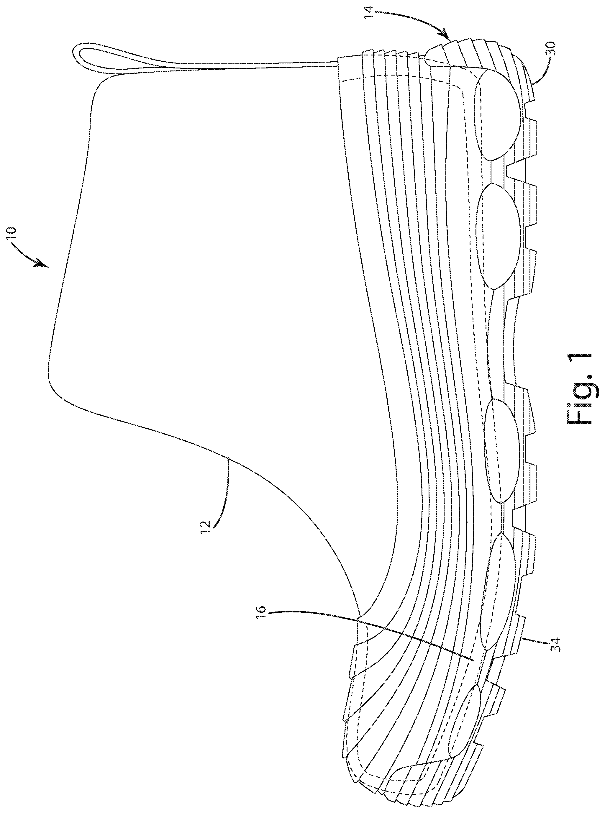
[0021] FIG. 1 is a side view of footwear of a current embodiment illustrating a gripping sole assembly;
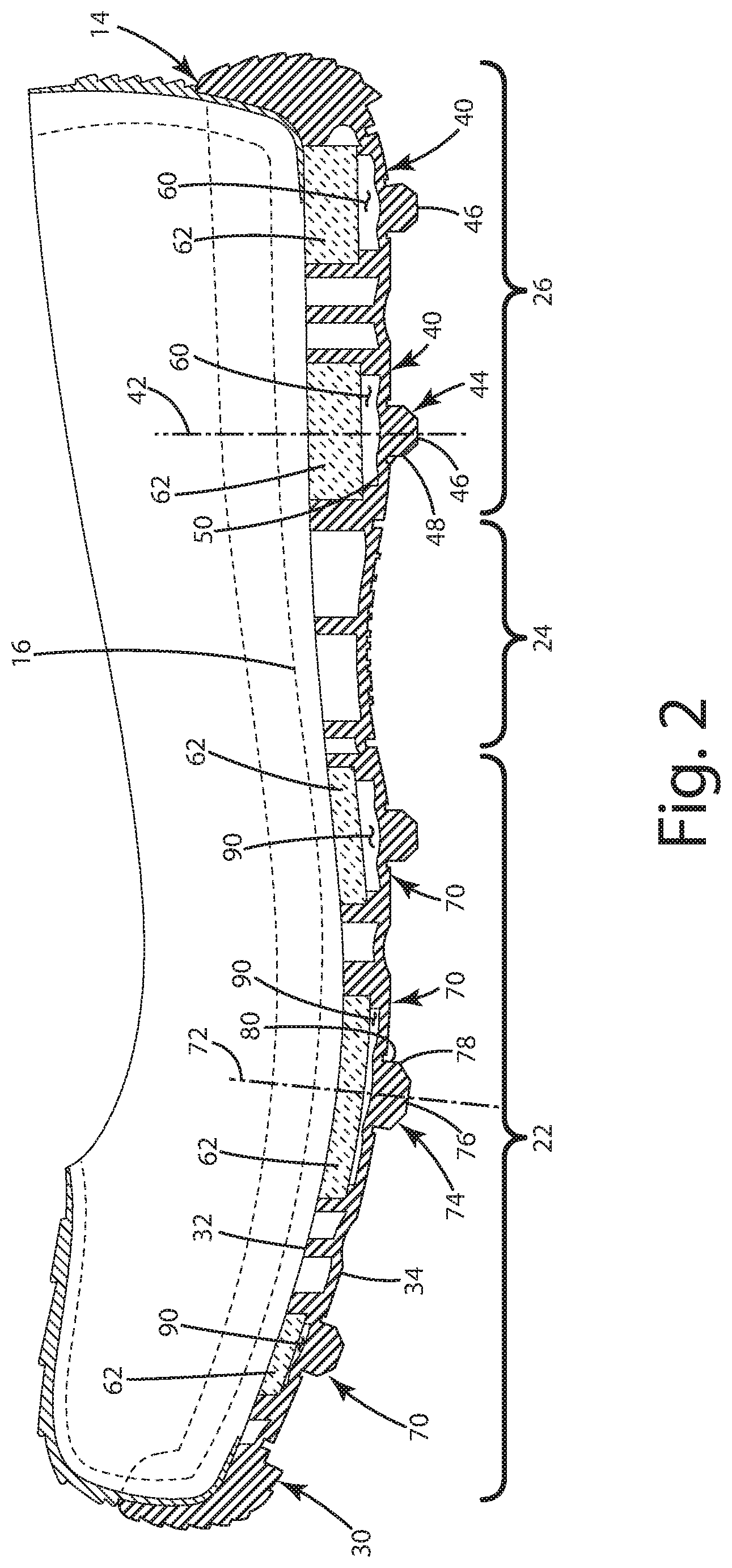
[0022] FIG. 2 is a section view of the footwear illustrating multiple gripping pods of the sole assembly;
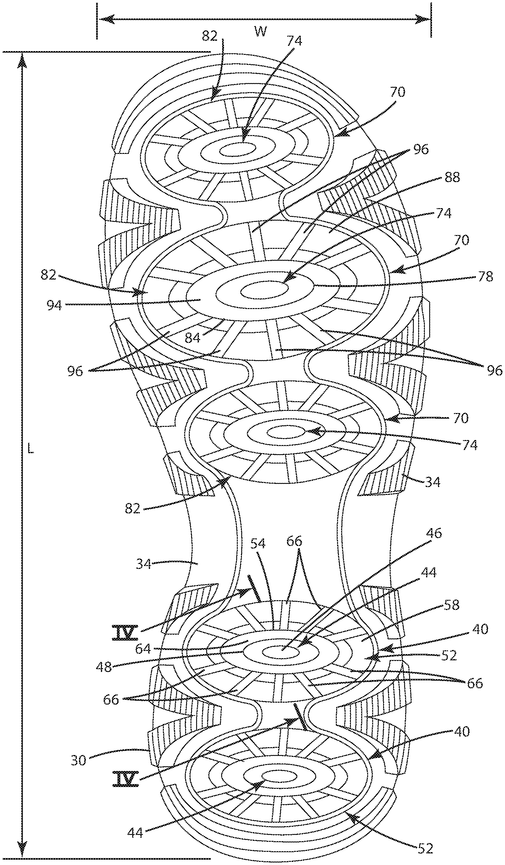
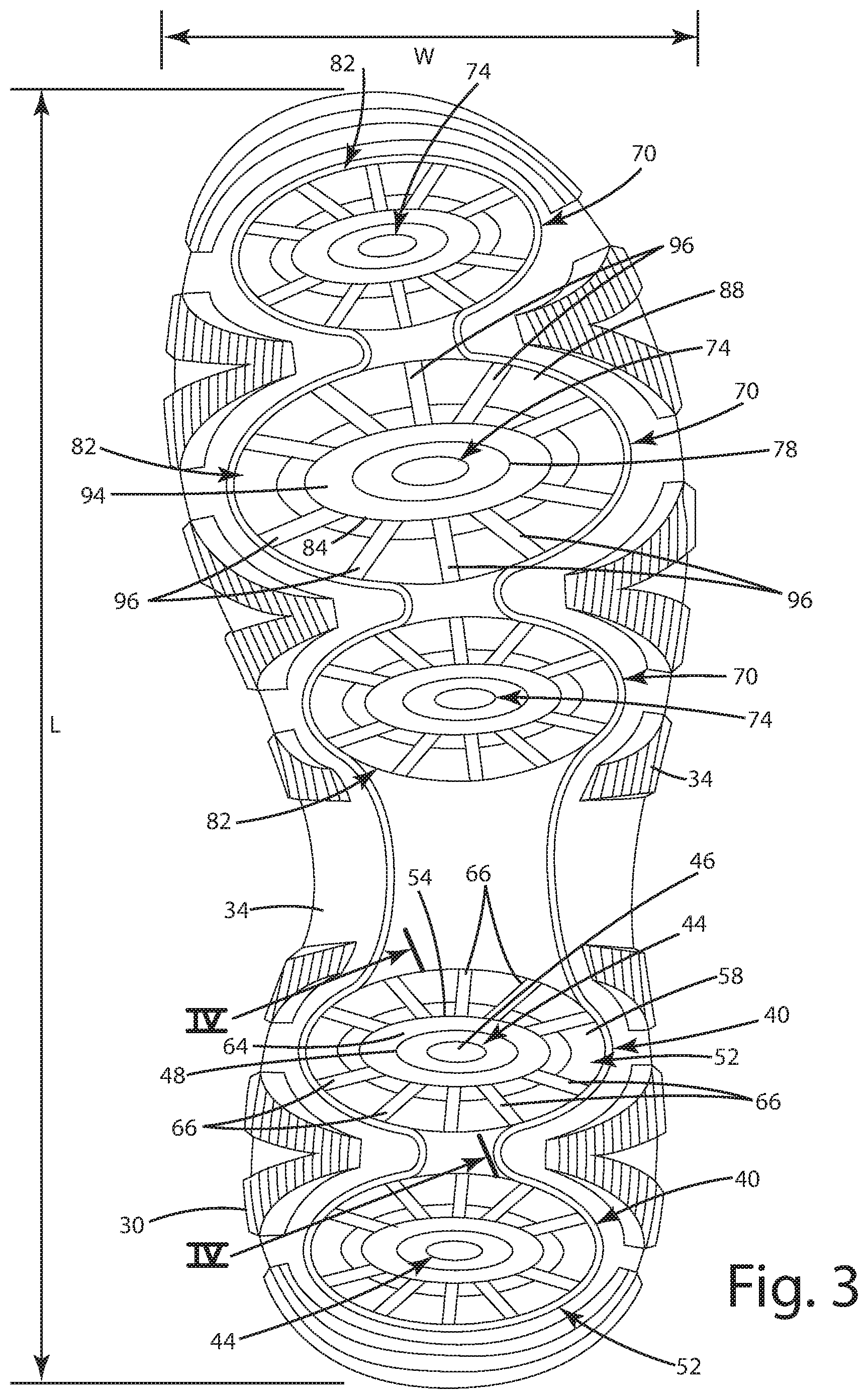
[0023] FIG. 3 is a bottom view of the sole assembly;
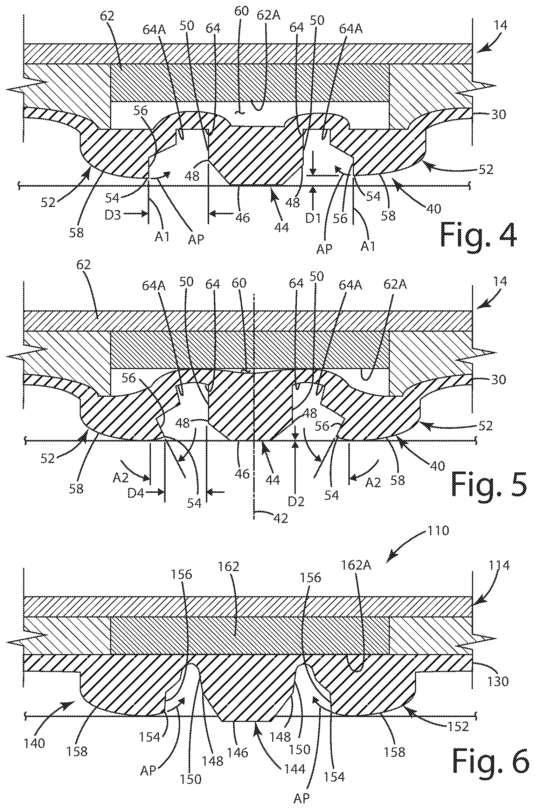
[0024] FIG. 4 is a section view of a gripping pod in an extended mode;
[0025] FIG. 5 is a section view of the gripping pod in a retracted or gripping mode;
[0026] FIG. 6 is a section view of a gripping pod in an extended mode of a sole assembly of an alternative embodiment;
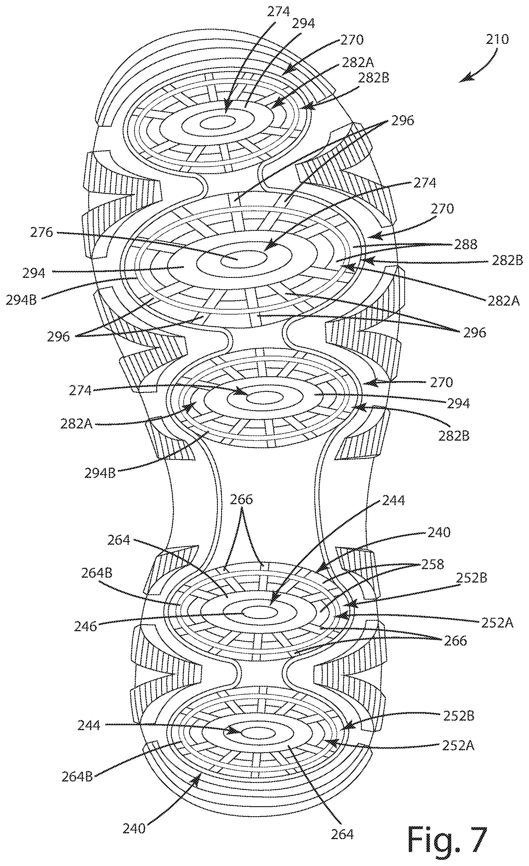
[0027] FIG. 7 is a bottom view of the sole assembly of an alternative embodiment; and
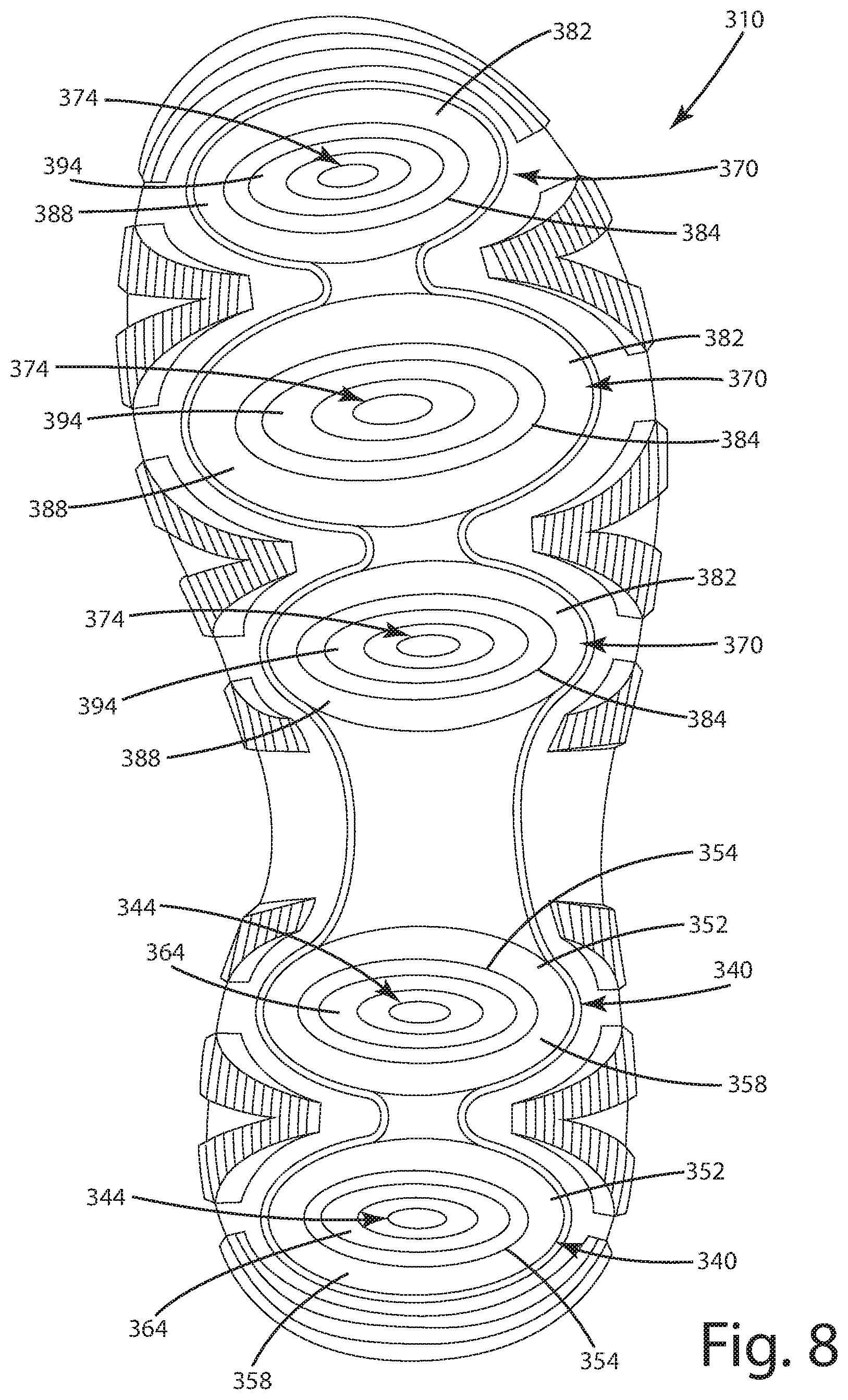
[0028] FIG. 8 is a bottom view of the sole assembly according to an alternative embodiment.
DESCRIPTION OF THE CURRENT EMBODIMENTS
[0029] A current embodiment of the footwear is illustrated in FIGS. 1-5, and generally designated 10. In these embodiments, the improved article of footwear includes a sole construction configured to enhance engagement of footwear with terrain features and provide improved traction.
[0030] Although the current embodiments are illustrated in the context of a winter boot or water resistant shoe, they may be incorporated into any type or style of footwear, including performance shoes, hiking shoes, trail shoes and boots, hiking boots, work boots, all-terrain shoes, barefoot running shoes, athletic shoes, running shoes, sneakers, conventional tennis shoes, walking shoes, multisport footwear, casual shoes, dress shoes or any other type of footwear or footwear components. Generally, the shoe is well suited for wet or slippery surfaces, including where those surfaces are flat or planar. For example, the shoe and the lugs described herein can operate in concert to grab an underlying ground surface. This can provide reactive and dynamic traction to the sole assembly and footwear, thus enabling the wearer to have confidence in their footing, including on a wet or otherwise slippery surface.
[0031] It also should be noted that directional terms, such as "vertical," "horizontal," "top," "bottom," "upper," "lower," "inner," "inwardly," "outer" and "outwardly," are used to assist in describing the invention based on the orientation of the embodiments shown in the illustrations. Further, the terms "medial," "lateral" and "longitudinal" are used in the manner commonly used in connection with footwear. For example, when used in referring to a side of the shoe, the term "medial" refers to the inward side (that is, the side facing the other shoe) and "lateral" refers to the outward side. When used in referring to a direction, the term "longitudinal direction" refers to a direction generally extending along the length of the shoe between toe and heel, and the term "lateral direction" refers to a direction generally extending across the width of the shoe between the medial and lateral sides of the shoe. The use of directional terms should not be interpreted to limit the invention to any specific orientation. Further, as used herein, the term "arch region" (or arch or midfoot) refers generally to the portion of the footwear or sole assembly corresponding to the arch or midfoot of the wearer's foot; the term "forefoot region" (or forefoot) refers generally to the portion of the footwear forward of the arch region corresponding to the forefoot (for example, including the ball and the toes) of a wearer's foot; and the term "heel region" (or heel) refers generally to that portion of the footwear rearward of the arch region corresponding to the heel of the wearer's foot. The forefoot region 22, arch region or mid-foot region 24, and heel region 26 generally are identified in FIG. 2. However, it is to be understood that delineation of these regions may vary depending upon the configuration of the sole assembly and/or footwear.
[0032] With reference to FIG. 2, the footwear 10 can include a sole assembly 14. The sole assembly 14 includes a lowermost or ground contacting surface which itself may include multiple lugs, treads, spikes, cleats and/or other features designed to enhance traction between the footwear 10 and in underlying surface. The sole assembly 14 can include one or more different components, such as an outsole 30, a midsole 16, and/or an insole or footbed (not shown). However, more or fewer elements of the sole assembly 14 can be included in some embodiments. For example, some embodiments can exclude the footbed, while other embodiments can include only the footbed and an outsole. The sole assembly 14 can include EVA foam with a cushioning top portion and a firmer, wear resistant bottom portion. The components of the sole assembly 14 may individually and/or collectively provide the article of footwear 10 with a number of attributes, such as support, rigidity, flexibility, stability, cushioning, comfort, reduced weight, and/or other attributes. Generally, regardless of which components are present, the sole assembly 14 can form the bottommost portion of the footwear 10. The sole assembly 14 includes a side-to-side width W and a heel-to-toe longitudinal length L, illustrated in FIG. 3.
[0033] The footwear 10 can include a textile upper 12 and the sole assembly 14. The upper 12 can be formed from a variety of material elements joined together to cover at least a portion of the wearer's foot. The material elements can be selected based on the intended uses of the article of footwear 10, and can include synthetic textiles, mesh textiles, polymers or leather, for example. The upper 12 is generally constructed to not impede the flexibility of the sole assembly 14, and can include stretchable or elastic material elements. For example, the material elements can include Lycra, Neoprene or Spandex. The upper 12 can include one or more closure elements, including for example shoelaces or hook and loop fasteners. The upper 12 additionally includes an upper opening for receiving the wearer's foot and a lower periphery for attachment to the sole assembly 14.
[0034] The footbed can be positioned within the void defined by the upper and is generally non-stretchable and lightweight and is joined to the upper to provide a void for receipt of the wearer's foot. The footbed can be constructed from a sheet of material, such as foam, EVA, PU, latex, gel or other materials, and by virtue of its compressibility, provide cushioning, and may also conform to the foot in order to provide comfort, support, and stability. The lower peripheral allowance or edge of the upper 12 can be stitched, cemented, or otherwise fastened to the footbed around the perimeter of the footbed. The sole assembly 14 can be combined with any other type or style of upper construction capable of being suitably joined with the outsole 30, for example a Strobel construction. The joining of the sole assembly/outsole and the upper can be accomplished using adhesives, cement, injection molding, pour molding or any other technique used to join an upper and sole.
[0035] The midsole 16 can be positioned below the footbed, and can be constructed from a material having a density that is generally less dense than the density of the outsole 30; for example, ethyl vinyl acetate (EVA), polyurethane (PU), latex, foam, a gel or other materials. Generally the density of the midsole 16 is such that it compresses relatively easily to provide cushion to the wearer's foot, for example, the heel. The midsole material can have a durometer, optionally about 30 Asker C to about 65 Asker C, further optionally about 42 Asker C to about 48 Asker C, and even further optionally about 45 Asker C or about 43 Asker C. In general, harder materials have more wear resistance, but they are also less flexible. Conversely, softer materials possess less wear resistance, but are more flexible.
[0036] The outsole 30 can be joined to the upper 12 and disposed below the midsole 16. The outsole 30 includes an upper surface 32 and a lowermost surface 34. The outsole 30 can include multiple lugs and/or treads that extend downward, as described below. The lugs and treads can be arranged as desired, and not necessarily in a repeating pattern. The lugs and treads can include one or more geometric shapes. The outsole 30 can be constructed from one or more materials, for example, natural or synthetic rubber, thermoplastic polyurethane elastomers (TPU), nylon, polymer blends, wear resistant polymers, elastomers and/or other materials. Other materials, such as fiber-reinforced polymers can be used, which can include epoxy, polyethylene or thermosetting plastic reinforced with carbon, glass and/or aramid fibers for enhanced protection. The outsole material can have a durometer, optionally about 40 Shore A to about 70 Shore A, further optionally about 68 Shore A to 72 Shore A.
[0037] As shown in FIG. 2, the sole assembly 14 can include one or more first gripping pods 40 having a first central axis 42 and a first actuator lug 44 generally aligned with, and optionally centered on, the first central axis 42. The first gripping pod 40 can be interspersed amongst treads and other lugs and can be integrally formed with the outsole 30. The outsole 30 can be of a preselected thickness, selected to provide the desired flexibility between individual lugs, treads, regions and/or portions of the outsole 20. The actuator lug 44 can be constructed from a material having a selected durometer and a coefficient of static friction.
[0038] Referring to FIGS. 2-4, the first actuator lug 44 can include an actuator lug ground contacting surface 46 defining a periphery 48 and an exterior actuator lug wall 50 that extends upwardly from the actuator lug ground contacting surface 46. While the first actuator lug 44 is shown as being ovate in shape, it should be understood that the lug can include one or more geometric shapes. The height of the actuator lug 44 can vary, depending on how much gripping action is desired. Further, the actuator lug ground contacting surface 46 transitions to the exterior actuator lug wall 50 generally at the periphery 48 and may include a chamfer, rounded corner, or the like at that interface or transition.
[0039] As shown in FIGS. 3-8, the first gripping pod 40 can include at least one first lug ring 52 that surrounds or encircles the first actuator lug 44 and is disposed radially outward from the exterior actuator lug wall 50. The first lug ring 52 can include a lug ring interior edge 54 and a lug ring interior wall 56 that face generally toward the exterior actuator lug wall 50. The first lug ring 52 lowermost surface defines a lug ring ground contacting surface 58. The lug ring interior edge 54 is defined at the intersection of the lug ring interior wall 56 and the lug ring ground contacting surface 58. The lug ring interior edge 54 extends around the periphery of the first lug ring 52, and while the lug ring interior edge 54 is show as being substantially a right-angle corner, the lug ring interior edge 54 can include a rounded corner or chamfer, both of which can be considered a corner herein, along with an actual right-angle corner where two surfaces intersect at 90.degree. to one another. The first lug ring 52 can follow the shape of the actuator lug 44, generally surrounding the exterior actuator lug wall 50. Optionally, the lug ring 52 can be disposed around all or a portion of the actuator lug 44.
[0040] The actuator lug 44 can be "taller" than the lug ring 52. The actuator lug ground contacting surface 46 extends a first distance D1 below the lug ring ground contacting surface 58 when the sole assembly is placed on a surface, such as a horizontal surface. Put another way, the first distance D1 can be, and can include, at least 1 mm. In one example, the actuator lug 44 can be taller than the adjacent lug ring ground contacting surface 58 by the distance D1. This distance can be optionally at least 1.0 mm, further optionally 1.0 mm to 5.0 mm, inclusive, further optionally 1.0 mm to 8.0 mm, inclusive, yet further optionally, 1.0 mm to 12.0 mm, inclusive. In addition, the lug ring interior edge 54 and the exterior actuator lug wall 50 are separated a distance D3.
[0041] This distance D3 can be optionally at least 1.0 mm, further optionally 1.0 mm to 5.0 mm, inclusive, further optionally 1.0 mm to 8.0 mm, inclusive, yet further optionally, 1.0 mm to 12.0 mm, inclusive. The first gripping pod 40 can include a first collapse compartment 60. The first collapse compartment 60 can be a substantially open space defined in the sole assembly 14 and disposed above the first actuator lug 44 and the first lug ring 52. The collapse compartment 60 can have a substantially similar peripheral shape as the first actuator lug 44 and first lug ring 52, however, other shapes are also contemplated. Optionally, a backer, such as a soft material 62 can be included within the collapse compartment 60, the purpose of which will be discussed below. The material 62 can be a material having a density that is generally less dense than the density of the outsole 20; for example, ethyl vinyl acetate (EVA), polyurethane (PU), latex, a gel or other materials. Generally, the density of the material 62 can be such that it compresses relatively easily. The material 62 can be sized and shaped so as to leave a gap between a lower surface 62A thereof and the upper surface 32 of the outsole 30. This gap can be optionally 0.1 mm to 10 mm, inclusive, further optionally, 1 mm to 6 mm, inclusive.
[0042] Deferring to FIGS. 3-4, a groove 64 can be defined between the first actuator lug 44 and the surrounding first lug ring 52. The groove 64 can extend upward, toward the midsole 16, and can follow the peripheral shape of the exterior actuator lug wall 50. The groove 64 surrounding the first actuator lug 44 provides localized flexibility to the outsole 30 so that the actuator lug 44 can more readily move upward toward the collapse compartment 60, as described below. The groove 64 depth can be selected to alter the amount of movement of the lug ring 52 toward the actuator lug 44 and/or one another. The base 64A or uppermost portion of the groove 64 also can be thinned or constructed from a different material than the lug ring 52 to alter the amount of movement of the lug ring 52. For example, the base 64A can be softer or thinner than the lug ring 52 to facilitate collapse of the ring 52 toward the central axis 42 of the gripping pod and/or the actuator lug 44, as described below. The transition of the groove 64 to the lug ring interior edge 54 can include a chamfer, rounded corner, or the like.
[0043] The sole assembly 14 also can include one or more second gripping pods 70 similar to the first gripping pod 40 described above. A second gripping pod 70 can include a second actuator lug 74 aligned with and/or centered on a second central axis 72 and a second lug ring 82 surrounding the second actuator lug 74. The second gripping pod 70 also includes a second collapse compartment 90 defined by the sole assembly 14 above the second actuator lug 74 and second lug ring 82. Additionally, a soft material 62 can be included within the second collapse compartment 90.
[0044] As illustrated in the exemplary embodiment of FIG. 3, the second gripping pod 70 and the first gripping pod 40 can be distal from one another. The first gripping pod 40 is shown located in the heel region 26 of the footwear 10, and the second gripping pod 70 is shown located in the forefoot region 22 of the footwear 10. According to one example, the gripping pods 40, 70 can extend across a majority of the side-to-side width W of the sole assembly 14 in their respective locations. While the illustrated example shows two first gripping pods 40 and three second gripping pods 70, more or fewer of either pod is contemplated herein, as well as other arrangements of the pods. Optionally, gripping pods 40, 70 can include different configurations and different numbers of lug rings 52, 82, depending on the application. The lug rings 52, 82 also can vary in structure, height, and location relative to one another and the actuator lug 44, 74 depending on the location along the sole assembly 14, and/or location in the sole assembly 14 along the heel-to-toe longitudinal length L.
[0045] The gripping pods 40, 70 also can include multiple channels or voids 66, 96 that are upwardly recessed into the lug ring ground contacting surface 58, 88 and extend through the lug ring interior edge 54, 84. For example, the voids 66, 96 extend radially away from the actuator lugs 44, 74 and can be spaced, evenly or unevenly, around the lug rings 52, 82. The lug ring ground contacting surface 58, 88 and the lug ring interior edge 54, 84 can therefore be interrupted by the voids 66, 96 such that the lug ring ground contacting surface 58, 88 is discontinuous. The voids 66, 96 can provide localized flex in the surrounding areas. The voids 66, 96 can be linear, curved, angled, segmented, circular, and/or polygonal in cross-section.
[0046] When the article of footwear 10 is worn, the shape of the outsole 30 can change when the wearer exerts pressure on the shoe as a result of the wearer's weight and contact with the ground surface. More particularly, the first gripping pod 40 and the second gripping pod 70 are each configured to move between an extended mode, illustrated in FIGS. 2 and 4, and a retracted or gripping mode, illustrated in FIG. 5. In the extended mode, the gripping pod 40, 70 is not under a compressive force due to a wearer's weight. In the gripping mode, the gripping pod 40, 70 is under the compressive force due to the wearer's weight. It should be understood that the gripping pods 40, 70 are independent and can be in the extended or gripping mode regardless of which mode the other pod is in. In some cases, for example, when all the pods are engaging the ground surface, the gripping pods can all be in the same mode.
[0047] Referring to FIGS. 4-5, in the gripping mode, the gripping pods 40, 70 at least partially collapse in upon themselves and/or up into the sole assembly to grip underfoot surfaces and terrain. Referring to the first gripping pod 40, when the footwear 10 is worn and initially contacts the ground to bear the weight of the wearer, the first actuator lug 44 engages the ground surface before the first lug ring 52 and moves upward, at least partially, into and/or toward the first collapse compartment 60 in the sole assembly 14. The upward movement of the first actuator lug 44 pulls the adjacent lug ring 52 toward it. The inward collapse of the first actuator lug 44 and pull in of the first lug ring 52 causes those elements to move toward the first central axis 42 of the first gripping pod 40 and grip the ground surface therebelow with a predetermined force. The density of the material 62 within the collapse compartment 60 can be selected to provide a sufficient amount of compression to allow the first gripping pod 40 to collapse as desired. The actuator lug 44 and the lug ring 52 collapse inward into the softer foam material 62 when transitioning from the extended mode to the gripping mode.
[0048] Optionally, the second gripping pod 70 collapses in the same manner as the first gripping pod 40. The second actuator lug 74 and the second lug ring 82 collapse at least partially into the second collapse compartment 90, with the second lug ring 82 moving toward the second central axis 72 of the second gripping pod 70. In this manner, a portion of the second lug ring 82 moves away from the first central axis 42 of the first gripping pod 40, while a second portion of the second lug ring 82 moves toward the first central axis 42 of the first gripping pod 40.
[0049] During the wearer's gait cycle and transition between the extended mode and the gripping mode, the lug ring interior edge 54, 84 travels toward the exterior actuator lug wall 50, 80, optionally following a substantially curvilinear or arcuate path AP, illustrated in FIG. 4. When this occurs, the interior edge 54, 84 of the lug ring 52, 82 can raise above the ground contacting surface 46, 76 of the actuator lug 44, 74, as shown in FIG. 5. The lug ring interior edge 54, 84 also can travel on the arcuate path AP toward the interior wall 56, 86 such that part of the ground contacting surface 58, 88 of the lug ring 52, 82 is no longer at the same horizontal level as the actuator ground contacting surface 46, 86. In contrast, the actuator lugs 44, 74 travel along a substantially linear path upward toward respective collapse compartments 60, 90 during the transition to the gripping mode from the extended mode.
[0050] In the extended mode, the actuator lug ground contacting surface 46, 86 can be disposed the first distance D1 (see FIG. 4) below the lug ring ground contacting surface 58, 88. During transition to the gripping mode, the actuator lug ground contacting surface 46, 86 retracts upward relative to the lug ring ground contacting surface 46, 86. In gripping mode, the actuator lug ground contacting surface 46, 86 can be disposed a second distance D2 (see FIG. 5) below the lug ring ground contacting surface 58, 88. The second distance D2 can be less than the first distance D1. As an example, the first distance D1 can be at least 1 mm, inclusive, and the second distance D2 is therefore less than 1 mm.
[0051] Additionally, in the extended mode, the lug ring interior wall 56, 86 can be disposed at a first angle A1 (see FIG. 4) relative to a vertical plane. During transition to the gripping mode, the lug ring interior wall 56, 86 is pulled and/or tilts toward the actuator lug 44, 74 indicated by the arrows in FIG. 4. Once in gripping mode, the lug ring interior wall 56, 86 can be disposed at a second angle A2 (see FIG. 5) relative to the vertical plane. The second angle A2 can be at least 2 degrees greater than the first angle A1. The first angle A1, as illustrated in FIG. 4, appears substantially vertical; however, angles other than vertical are contemplated herein. For example, the first angle A1 can optionally be positive or negative about 20.degree. relative to the vertical plane, and further optionally positive or negative about 30.degree., 45.degree., or 60.degree. relative to the vertical plane.
[0052] The lug ring interior edge 54 and the exterior actuator lug wall 50 are separated the first distance D3 (see FIG. 4) in the extended mode. Upon transition to the gripping mode, the lug ring interior edge 54 and the exterior actuator lug wall 50 are separated a second distance D4 (see FIG. 5). The second distance D4 is less than the first distance D3. When the gripping pod 40, 70 converts from the extended mode to the gripping mode, the lug ring interior edge 54, 84 and/or interior wall 56, 86 move toward the actuator lug exterior wall 50, 80. When this occurs the distance between these elements decreases from the first distance D3 to the lesser distance D4. Accordingly, any ground surface material between the lug ring 52, 82 and the actuator lug 44, 74 can be grabbed, gripped, or pinched between the actuator lug 44, 74 and the lug ring 52, 82. In particular, the ground surface material is grabbed or gripped between the lug ring interior edge 54, 84 and/or interior wall 56, 86 and the actuator lug exterior wall 50, 80 to improve traction.
[0053] A first alternative embodiment of the footwear is illustrated in FIG. 6, and generally designated 110. This footwear can be similar in structure, function, and operation to the embodiment described above with some exceptions. For example, this footwear 110 can include a backer 162 that substantially fills the collapse compartment 160, leaving no gap as described in the embodiment above. The gripping pod 140, 170 overlays the softer foam backer 162 to provide an amount of compression. The actuator lug 144, 174 and the ring lug 152, 182 can collapse inward into the soft backer 162 when transitioning from the extended mode to the gripping mode. The footwear 110 also can eliminate the groove of the previous embodiment, to affect the localized flexibility of the outsole 130 as desired. While the backer 162 and eliminated groove can change the response of the footwear, the collapse of the pods 140, 170 is generally similar as the collapse described above, and the actuator lugs 144, 174 and lug rings 152, 182 still compress and pull in as described above.
[0054] An alternative embodiment of the footwear is illustrated in FIG. 7, and generally designated 210. This footwear can be similar in structure, function, and operation to the embodiment described above with some exceptions. The gripping pod 240 can optionally include two or more lug rings 252 disposed concentrically about one another. Between a first lug ring 252a and a more outward positioned second lug ring 252b, a second groove 264b can be defined. The geometry and material of the groove can be selected as described above with respect to the previous embodiment. Additionally, the collapse compartment 260 can be larger, so as to be disposed above the first actuator lug 244, the first lug ring 252a, and the second lug ring 252b.
[0055] During the transition from the extended mode to the gripping mode, the second lug ring interior wall 256b is pulled and/or tilts toward the first lug ring 252a, in a similar manner as the lug ring interior wall of the first embodiment. However, the axis of rotation for the second lug ring interior wall 256b is different than (separate and spaced from) the axis of rotation for the first lug interior wall 256a. That is to say that the second lug ring interior wall 256a will not necessarily collapse in at the same angle (A2) as the first lug interior wall 256a. Given its distance from the central axis 242, the pull from the upward movement of the actuator lug 244 can be less than the pull experienced by the first lug ring 252a. It should be understood that both lug rings 252a and 252b can tilt during the transition from the extended mode to the gripping mode, however. Of course, it should also be understood that, while the description above is relative to the first gripping pod 240 including two lug rings 252, the second gripping post 270 also can include multiple lug rings and need not be described in greater detail.
[0056] Another alternative embodiment of the footwear is illustrated in FIG. 8 and generally designated 310. This footwear can be similar in structure, function, and operation to the embodiment described above with some exceptions. For example, this footwear 310 can eliminate the voids in the lug ring interior edge 354, 384 and the lug ring ground contacting surface 358, 388. In this manner, the ground contacting surfaces 358, 388 are continuous.
[0057] Without the voids of the first embodiment, the lug ring 352 is continuous and can completely surround an outer periphery of the actuator lug 344. When the gripping pod 340 engages a generally flat or planar surface, collapse of the pod 340 can produce a negative pressure so that the gripping pod 340 is essentially, or at least partially, suctioned to the surface therebelow. As such, when the lug ring 352 is continuous, the gripping pod 340 produces suction upon its collapse, providing improved traction on wet or slippery surfaces, particularly where those surfaces are flat or planar. Of course, the same is true of the second gripping pod 370. It is contemplated that some, but not necessarily all, of the gripping pods be continuous, while others include the voids and are therefore discontinuous.
[0058] The footwear of any of the above embodiments provides a sole assembly with exceptional traction. Where the gripping pods include the actuator lug and lug rings, those lugs can operate in concert to grab an underlying ground surface. This can provide reactive and dynamic traction to the sole assembly and footwear, thus enabling the wearer to have confidence in their footing. Additionally, where the lug ring is continuous, and the gripping pod produces suction upon its collapse, the sole assembly can provide improved traction on wet or slippery surfaces, particularly where those surfaces are flat or planar.
[0059] The various components and features of the embodiments herein, for example, the upper, sole or other footwear portions, can take on a variety of aesthetic forms, shapes and sizes. Although a particular component or feature can have a function, that feature can be expressed in different aesthetic manners to form an artistic design and/or purely ornamental design.
[0060] Directional terms, such as "vertical," "horizontal," "top," "bottom," "upper," "lower," "inner," "inwardly," "outer" and "outwardly," are used to assist in describing the invention based on the orientation of the embodiments shown in the illustrations. The use of directional terms should not be interpreted to limit the invention to any specific orientation(s).
[0061] The above description is that of current embodiments of the invention. Various alterations and changes can be made without departing from the spirit and broader aspects of the invention as defined in the appended claims, which are to be interpreted in accordance with the principles of patent law including the doctrine of equivalents. This disclosure is presented for illustrative purposes and should not be interpreted as an exhaustive description of all embodiments of the invention or to limit the scope of the claims to the specific elements illustrated or described in connection with these embodiments. For example, and without limitation, any individual element(s) of the described invention may be replaced by alternative elements that provide substantially similar functionality or otherwise provide adequate operation. This includes, for example, presently known alternative elements, such as those that might be currently known to one skilled in the art, and alternative elements that may be developed in the future, such as those that one skilled in the art might, upon development, recognize as an alternative. Further, the disclosed embodiments include a plurality of features that are described in concert and that might cooperatively provide a collection of benefits. The present invention is not limited to only those embodiments that include all of these features or that provide all of the stated benefits, except to the extent otherwise expressly set forth in the issued claims. Any reference to claim elements in the singular, for example, using the articles "a," "an," "the" or "said," is not to be construed as limiting the element to the singular. Any reference to claim elements as "at least one of X, Y and Z" is meant to include any one of X, Y or Z individually, and any combination of X, Y and Z, for example, X, Y, Z; X, Y; X, Z; and Y, Z.
* * * * *
D00000
D00001
D00002
D00003
D00004
D00005
D00006
XML
uspto.report is an independent third-party trademark research tool that is not affiliated, endorsed, or sponsored by the United States Patent and Trademark Office (USPTO) or any other governmental organization. The information provided by uspto.report is based on publicly available data at the time of writing and is intended for informational purposes only.
While we strive to provide accurate and up-to-date information, we do not guarantee the accuracy, completeness, reliability, or suitability of the information displayed on this site. The use of this site is at your own risk. Any reliance you place on such information is therefore strictly at your own risk.
All official trademark data, including owner information, should be verified by visiting the official USPTO website at www.uspto.gov. This site is not intended to replace professional legal advice and should not be used as a substitute for consulting with a legal professional who is knowledgeable about trademark law.