False Eyelash Conversion System, Applicator And Methods Of Using The Same
Bougie; Keri ; et al.
U.S. patent application number 16/587853 was filed with the patent office on 2020-04-30 for false eyelash conversion system, applicator and methods of using the same. The applicant listed for this patent is L'Attitude Lash Co., LLC. Invention is credited to Monte David Anderson, Keri Bougie.
| Application Number | 20200128896 16/587853 |
| Document ID | / |
| Family ID | 70327657 |
| Filed Date | 2020-04-30 |


| United States Patent Application | 20200128896 |
| Kind Code | A1 |
| Bougie; Keri ; et al. | April 30, 2020 |
FALSE EYELASH CONVERSION SYSTEM, APPLICATOR AND METHODS OF USING THE SAME
Abstract
A false eyelash conversion system and an applicator for use with an eyelash extension system are disclosed.
| Inventors: | Bougie; Keri; (San Diego, CA) ; Anderson; Monte David; (Colorado Springs, CO) | ||||||||||
| Applicant: |
|
||||||||||
|---|---|---|---|---|---|---|---|---|---|---|---|
| Family ID: | 70327657 | ||||||||||
| Appl. No.: | 16/587853 | ||||||||||
| Filed: | September 30, 2019 |
Related U.S. Patent Documents
| Application Number | Filing Date | Patent Number | ||
|---|---|---|---|---|
| 62753186 | Oct 31, 2018 | |||
| Current U.S. Class: | 1/1 |
| Current CPC Class: | A45D 2200/10 20130101; A41G 5/02 20130101; A45D 2/48 20130101; A45D 44/00 20130101 |
| International Class: | A41G 5/02 20060101 A41G005/02; A45D 44/00 20060101 A45D044/00; A45D 2/48 20060101 A45D002/48 |
Claims
1. An applicator for use with an eyelash extension system, comprising: a handle having a proximal end and a distal end; a frame extending from the distal end of the handle, wherein the frame comprises a first arm and a second arm; a first member coupled to a distal end of the first arm and a distal end of the second arm, wherein the first member comprises a first magnetic strip; and a second member movably coupled to a proximal end of the first arm and a proximal end of the second arm, wherein the second member comprises a second magnetic strip, and wherein the second member is movable between a first position and a second position.
2. The applicator of claim 1, wherein the first and second members are closer to each other when the second member is in the second position than when the second member is in the first position.
3. The applicator of claim 1, wherein the first member comprises an outer edge and an inner edge, wherein the first magnetic strip extends along at least a portion of a length of the first member, and wherein the first magnetic strip is movable between the inner edge and the outer edge of the first member.
4. The applicator of claim 1, wherein the second member includes an upper edge and a lower edge.
5. The applicator of claim 1, wherein the second magnetic strip extends along at least a portion of a length of the second member.
6. The applicator of claim 1, further comprising a control member disposed on the handle, the control member being configured to control a movement of the second member relative to the first member.
7. The applicator of claim 1, further comprising an actuation member disposed on the handle, the actuation member being configured to control a movement of the first magnetic strip from a third position to a fourth position.
8. The applicator of claim 1, wherein the first magnetic strip has a first magnetic force and the second magnetic strip has a second magnetic force different from the first magnetic force.
9. The applicator of claim 1, wherein the first and second magnetic strips each are at least partially surrounded by a non-magnetic strip.
10. The applicator of claim 1, wherein the eyelash extension system comprises a first strip comprising a plurality of magnetic elements, a second strip comprising a plurality of magnetic elements, and a third strip comprising a plurality of magnetic elements, and wherein a false eyelash strip is removably coupled between the first strip of the eyelash extension system and the second strip of the eyelash extension system.
11. The applicator of claim 8, wherein the first magnetic force is greater than the second magnetic force.
12. The applicator of claim 10, wherein the first magnetic strip of the applicator is releasably attachable to the first strip of the eyelash extension system and wherein the second magnetic strip of the applicator is releasably attachable to the third strip of the eyelash extension system.
13. A false eyelash conversion system, comprising: a first strip comprising at least one magnetic element; a second strip comprising at least one magnetic element, wherein the first strip and the second strip are hinged together through at least one connection member; and a third strip comprising at least one magnetic element, the third strip being configured to be releasably coupled to the second strip.
14. The false eyelash conversion system of claim 13, wherein the first strip and the second strip are configured to releasably couple a false eyelash strip therebetween.
15. The false eyelash conversion system of claim 13, wherein the first strip comprises a first plurality of magnetic elements, the second strip comprises a second plurality of magnetic elements, and the third strip comprises a third plurality of magnetic elements.
16. The false eyelash conversion system of claim 13, wherein the second strip and the third strip are configured to releasably couple a person's natural eyelashes therebetween.
17. The false eyelash conversion system of claim 15, wherein each of the first plurality of magnetic elements is aligned with a corresponding one of the second plurality of magnetic elements.
18. The false eyelash conversion system of claim 15, wherein the third strip is configured to be releasably coupled to the second strip by a magnetic attraction between the third plurality of magnetic elements and the second plurality of magnetic elements.
Description
CROSS-REFERENCE TO RELATED APPLICATIONS
[0001] This application claims the benefit of U.S. Provisional Patent Application No. 62/753,186, entitled "False Eyelash Conversion System, Applicator and Methods of Using the Same," filed on Oct. 31, 2018, the entirety of which is hereby incorporated herein by reference.
BACKGROUND
[0002] False eyelashes are generally affixed to the eyelid of the wearer to enhance the appearance of the natural eyelashes of the wearer with better curl, color, fullness, length, or other desirable physical characteristics. Conventional false eyelashes generally include synthetic hairs tied or adhered to a semi-flexible, rope-like strip formed from a textile or non-woven material. To affix the false eyelash to the eyelid of the wearer, an adhesive substance may be placed on a surface of the strip or directly on the eyelid just above the wearer's natural eyelashes. The strip of the false eyelash is then pressed against the wearer's eyelid, such that the false eyelash will be secured to the eyelid. Conventional adhesives may include, for example, latex adhesives, solvent-borne adhesives, pressure-sensitive adhesives (PSAs), and hot melt adhesives.
[0003] Convention adhesives may have one or more drawbacks, including stickiness, difficult or messy to apply, the inability to reuse the eyelash strip and potentially result in discomfort to remove adhesive from the wearer's eyelid. Therefore, it may be advantageous to utilize non-adhesive means, such as a magnetic force to affix a false eyelash to the eyelid of the wearer. Utilizing magnetic attraction may provide a fully-reusable, easy to apply, remove, and reapply, self-aligning false eyelash without the use of adhesives. For example, utilizing magnetic attraction may avoid the deformation of the false eyelash resulted in applying adhesives to affix the false eyelash to the wearer's eyelid and removing the false eyelash from the eyelid after use. In addition, the holding power of magnetic attraction may be greater and last longer than conventional adhesive materials, especially when exposed throughout the day to oils secreted by the wearer's eyelid. Unlike conventional adhesives, magnetic materials may not irritate the wearer' eyes and/or skins and may not leave any residue on the wearer's eyelid once removed.
DESCRIPTION OF THE DRAWINGS
[0004] The present disclosure can be better understood with reference to the following drawings and description. The components in the figures are not necessarily to scale, emphasis instead being placed upon illustrating the principles of the present disclosure. Moreover, in the figures, like-referenced numerals designate corresponding parts throughout the different views.
[0005] FIG. 1 is an illustration showing a perspective view of a false eyelash conversion system in accordance with certain aspects of the present disclosure.
[0006] FIG. 2 is an illustration showing a front view of the false eyelash conversion system of FIG. 1 in accordance with certain aspects of the present disclosure.
[0007] FIG. 3 is an illustration showing a side view of the false eyelash conversion system of FIG. 1 in accordance with certain aspects of the present disclosure.
[0008] FIG. 4 is an illustration showing a perspective view of the false eyelash conversion system of FIG. 1 to be coupled to a set of false eyelashes in accordance with certain aspects of the present disclosure.
[0009] FIG. 5 is an illustration showing a rear view of an embodiment of an applicator to be used with, for example, the false eyelash conversion system of FIG. 1 in accordance with certain aspects of the present disclosure, the applicator including a handle, a frame, a first member, and a second member.
[0010] FIG. 6 is an illustration showing a side view of the applicator of FIG. 5 in accordance with certain aspects of the present disclosure.
[0011] FIG. 7 is an illustration showing a front view of the applicator of FIG. 5 in accordance with certain aspects of the present disclosure.
[0012] FIG. 8 is an illustration showing a rear view of the applicator of FIG. 5 in accordance with certain aspects of the present disclosure, the applicator including the second member that is in a first position.
[0013] FIG. 9 is an illustration showing a partial, enlarged perspective view of a portion of the applicator of FIG. 8 in accordance with certain aspects of the present disclosure.
[0014] FIG. 9A is an illustration showing a partial, cross-sectional view of the portion of the applicator of FIG. 9 in accordance with certain aspects of the present disclosure.
[0015] FIG. 10 is an illustration showing a rear view of the applicator of FIG. 5 in accordance with certain aspects of the present disclosure, the applicator including the second member that is moved to a second position by manipulating a control member.
[0016] FIG. 11 is an illustration showing a partial, enlarged perspective view of a portion of the applicator of FIG. 10 in accordance with certain aspects of the present disclosure.
[0017] FIG. 11A is an illustration showing a partial, cross-sectional view of the portion of the applicator of FIG. 11 in accordance with certain aspects of the present disclosure.
[0018] FIG. 12 is an illustration showing a front view of the applicator of FIG. 7 in accordance with certain aspects of the present disclosure, the applicator including the second member that is in the first position and a first magnetic strip that is in a third position.
[0019] FIG. 13 is an illustration showing a partial, enlarged perspective view of a portion of the applicator of FIG. 12 in accordance with certain aspects of the present disclosure, the applicator including the second member that is in the second position and the first magnetic strip that is in the third position.
[0020] FIG. 13A is an illustration showing a partial, cross-sectional view of the portion of the applicator of FIG. 13 in accordance with certain aspects of the present disclosure, the applicator including the second member that is in the second position and the first magnetic strip that is in the third position.
[0021] FIG. 14 is an illustration showing a front view of the applicator of FIG. 12 in accordance with certain aspects of the present disclosure, the applicator including the second member that is in the first position and the first magnetic strip being moved to a fourth position by manipulating an actuation member.
[0022] FIG. 15 is an illustration showing a partial, enlarged perspective view of a portion of the applicator of FIG. 14 in accordance with certain aspects of the present disclosure, the applicator including the second member that is in the second position and the first magnetic strip being moved to the fourth position by manipulating the actuation member.
[0023] FIG. 15A is an illustration showing a partial, cross-sectional view of the portion of the applicator of FIG. 15 in accordance with certain aspects of the present disclosure, the applicator including the second member that is in the second position and the first magnetic strip being moved to the fourth position by manipulating the actuation member.
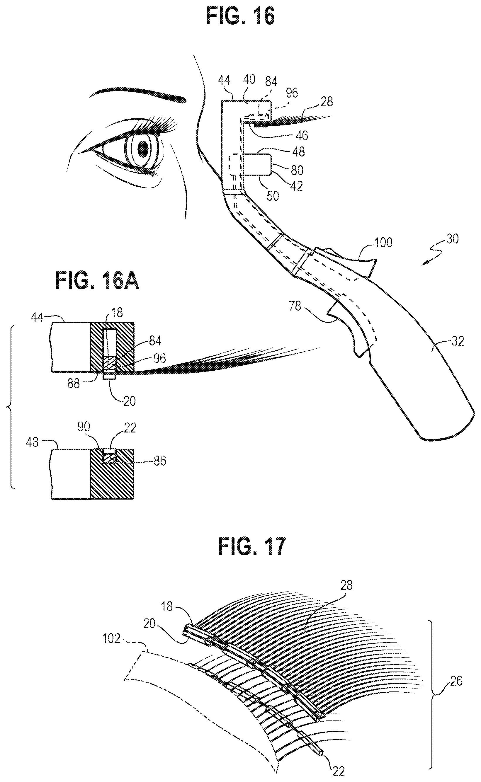
[0024] FIG. 16 is an illustration showing a side view of the applicator of FIG. 6 with a magnetic false eyelash extension system removably coupled thereto to be applied to a wearer's natural eyelashes in accordance with certain aspects of the present disclosure.
[0025] FIG. 16A is an illustration showing a partial, cross-sectional view of a portion of the applicator of FIG. 16 with the magnetic false eyelash extension system removably coupled thereto in accordance with certain aspects of the present disclosure.
[0026] FIG. 17 is an illustration showing a partial, enlarged perspective view of the magnetic false eyelash extension system removably coupled to the applicator of FIG. 16, the magnetic false eyelash extension system positioned such that the wearer's natural eyelashes are disposed between opposing surfaces of the magnetic false eyelash extension system.
[0027] FIG. 18 is an illustration showing a side view of the applicator of FIG. 16 being applied to the wearer's natural eyelashes in accordance with certain aspects of the present disclosure, the wearer's natural eyelashes are sandwiched by the first and second members of the applicator when the first magnetic strip is in the third position and the second member is moved to the second position by manipulating the control member.
[0028] FIG. 18A is an illustration showing a partial, cross-sectional view of a portion of the applicator of FIG. 18 being applied to the wearer's natural eyelashes in accordance with certain aspects of the present disclosure, the wearer's natural eyelashes are sandwiched by the first and second members of the applicator when the first magnetic strip is in the third position and the second member is moved to the second position.
[0029] FIG. 19 is an illustration showing a side view of the applicator of FIG. 16 being applied to the wearer's natural eyelashes in accordance with certain aspects of the present disclosure, the wearer's natural eyelashes are sandwiched by the first and second members of the applicator when the first magnetic strip is moved to the fourth position by manipulating the actuation member.
[0030] FIG. 19A is an illustration showing a partial, cross-sectional view of a portion of the applicator of FIG. 19 being applied to the wearer's natural eyelashes in accordance with certain aspects of the present disclosure, the wearer's natural eyelashes are sandwiched by the first and second members of the applicator when the first magnetic strip is moved to the fourth position.
[0031] FIG. 20 is an illustration showing a side view of the applicator of FIG. 16 being removed from the wearer's natural eyelashes after coupling the magnetic false eyelash extension system to the wearer's natural eyelashes in accordance with certain aspects of the present disclosure, the second member of the applicator is in the first position while the first magnetic strip is in the fourth position.
[0032] FIG. 21 is an illustration showing a partial, enlarged perspective view of the magnetic false eyelash extension system coupled to the wearer's natural eyelashes of FIG. 20 in accordance with certain aspects of the present disclosure.
[0033] FIG. 22 is an illustration showing a perspective view of another embodiment of an applicator to be used with, for example, the false eyelash conversion system of FIG. 1 in accordance with certain aspects of the present disclosure.
[0034] FIG. 22A is an illustration showing an enlarged perspective view of a portion of the applicator of FIG. 22 in accordance with certain aspects of the present disclosure.
DETAILED DESCRIPTION
[0035] Various aspects are described below with reference to the drawings in which like elements generally are identified by like numerals. The relationship and functioning of the various elements of the aspects may better be understood by reference to the following detailed description. However, aspects are not limited to those illustrated in the drawings or explicitly described below. It also should be understood that the drawings are not necessarily to scale, and in certain instances details may have been omitted that are not necessary for an understanding of aspects disclosed herein, such as conventional fabrication and assembly.
[0036] Certain aspects of the present disclosure relate to a false eyelash conversion system that may be used with various types of false eyelashes to convert the false eyelashes into a magnetic false eyelash extension system. When referring to the magnetic false eyelash extension system, the magnetic false eyelash extension system may be applied to the natural eyelashes in the upper eyelid of a wearer and/or the lower eyelid of the wearer. The magnetic false eyelash extension system may also be applied to either the left or the right eye of the wearer. For simplicity of explanation, unless otherwise stated, the description in the present disclosure references application to the eyelashes located in the upper eyelid of the wearer.
[0037] One general aspect of the present disclosure includes an applicator for use with an eyelash extension system, including: a handle having a proximal end and a distal end; a frame extending from the distal end of the handle, where the frame has a first arm and a second arm; a first member attached to a distal end of the first arm and a distal end of the second arm, where the first member has a first magnetic strip; and a second member movably attached to a proximal end of the first arm and a proximal end of the second arm, where the second member has a second magnetic strip, and where the second member is movable between a first position and a second position.
[0038] Another general aspect of the present disclosure includes a false eyelash conversion system, including: a first strip having at least one magnetic element; a second strip having at least one magnetic element, where the first strip and the second strip are hinged together through at least one connection member; and a third strip having at least one magnetic element, where the third strip is configured to be releasably coupled to the second strip.
[0039] Referring to FIGS. 1-4, a false eyelash conversion system 10 including a first strip 12, a second strip 14, and a third strip 16 is shown. The first strip 12 and the second strip 14 are hinged together through at least one connection member 24, and as shown, a plurality of connection members 24. The first strip 12 includes at least one, and as shown, a first plurality of magnetic elements 18 attached thereto and along a length of the first strip 12. The second strip 14 includes at least one, and as shown, a second plurality of magnetic elements 20 attached thereto and along a length of the second strip 14. The third strip 16 includes at least one, and as shown, a third plurality of magnetic elements 22 attached thereto and along a length of the third strip 16. The false eyelash conversion system 10 may be used with any type of false eyelash 28 to convert the false eyelash 28 into a magnetic false eyelash extension system 26 (as shown, for example, in FIGS. 4 and 17).
[0040] The first, second, and third strips 12, 14 and 16 may have substantially the same narrow and elongated configuration. In some embodiments, each strip 12, 14 and 16 may be shaped to mirror the contour of the wearer's eyelid edge. The length of each strip 12, 14 and 16 may be substantially the same (as shown in FIGS. 1-2), or may be different. Each strip 12, 14 and 16 may be long enough to substantially cover at least a portion of the wearer's eyelid edge. That is, the length of each strip 12, 14 and 16 may cover the entire length or a portion of the length of a wearer's eyelid edge. For example, each strip 12, 14 and 16 may have a length that is substantially the same as false eyelashes commonly used, such as from about 30 mm to 50 mm. It is also contemplated that each strip 12, 14 and 16 may have a length that is longer than a wearer's eyelid edge and/or than false eyelashes commonly used and then trimmed or cut to a desired length by the user to provide a customized length. Each strip 12, 14, and 16 may be composed of a textile, a non-woven material, a polymer (e.g. rubbers, plastics), or other suitable material (e.g. metals and/or alloys, such as Nitinol) that is thin, flexible, lightweight, and can be readily adaptable to the attachment of magnetic elements, be easily manipulated to accommodate a particular contour of the wearer's eyelid edge, and be easily to cut to cover a desired length of the wearer's eyelid edge.
[0041] The first, second and third plurality of magnetic elements 18, 20 and 22 may be composed of an inherently magnetic material, such as neodymium. In some embodiments, the magnetic elements 18, 20 and 22 may be composed of a magnetizable material, such as magnetite or any other ferrous material, which is magnetized after attachment to the respective strips 12, 14 and 16. In some embodiments, the first and second plurality of magnetic elements 18 and 20 may have opposite polarities such that the false eyelash 28 may be sandwiched and releasably coupled by the magnetic attraction between them (as shown in FIGS. 4 and 17). In this way, the false eyelash conversion system 10 sandwiching the false eyelash 28 may constitute a magnetic false eyelash extension system 26 that may be applied to the eyelid of the wearer to enhance the appearance of the wearer's natural eyelashes.
[0042] In some embodiments, the second and third plurality of magnetic elements 20 and 22 may have opposite polarities such that the magnetic false eyelash extension system 26 may be removably coupled to the wearer's natural eyelashes through the magnetic attraction between them (as shown in FIGS. 20 and 21). That is, when in use, the hinged-together first and second strips 12 and 14 sandwiching the false eyelash 28 is placed above the wearer's natural eyelashes and the third strip 16 is placed underneath the wearer's natural eyelashes, such that the false eyelash 28 is secured in place above the wearer's natural eyelashes through the magnetic attraction between the second and third strips 14 and 16. In some embodiments, the hinged-together first and second strips 12 and 14 may be placed underneath the wearer's natural eyelashes, and the third strip may be placed above the wearer's natural eyelashes. In some embodiments, the false eyelash conversion system 10 may additionally include a fourth strip (not shown) with magnetic elements attached thereto. The third strip 16 and the fourth strip may be hinged together in the same manner as the first and second strips 12 and 14. In this configuration, an additional false eyelash may be sandwiched by the third strip 16 and the fourth strip through magnetic attraction. When in use, the additional false eyelash may be secured in place underneath the wearer's natural eyelashes, which would add an additional layer of false eyelash to the false eyelash 28 secured in place above the wearer's natural eyelashes, thereby enhancing the appearance of the natural eyelashes of the wearer with even greater length and/or fullness.
[0043] As shown in FIGS. 1-2, the plurality of magnetic elements 18, 20 and 22 may have substantially the same configuration and in other embodiments they may be different. In some embodiments, each of the plurality of magnetic elements 18, 20 and 22 may have a narrow and elongated configuration extending substantially the same length of the respective strip 12, 14 or 16. The plurality of magnetic elements 18, 20 and 22 may be one long continuous magnet extending substantially the length of the respective strip 12, 14 or 16 or they may comprise a plurality of smaller spaced-apart magnets as shown generally in FIG. 1. It will be appreciated that various configurations and dimensions of the plurality of magnetic elements 18, 20 and 22 are also possible as desired and/or needed. In some embodiments, the plurality of magnetic elements 18, 20 and 22 each may be attached to a surface of the respective strip 12, 14 or 16.
[0044] In some embodiments, the plurality of magnetic elements 18, 20 and 22 each may substantially cover at least a portion of the respective strip 12, 14, or 16, such that the respective strips 12, 14, and 16 may be visible only in the portions that are not covered by one of the plurality of magnetic elements 18, 20 and 22. The plurality of magnetic elements 18, 20 and 22 may be spaced along or cover the entire length of the respective strips 12, 14 and 16. Each of the plurality of magnetic elements 18, 20, and 22 may be placed at any desired location along the length of the respective strip 12, 14 or 16. In some embodiments, each respective strip 12, 14 or 16 may have the same number of magnetic elements 18, 20 and 22. In some embodiments, when the first plurality of magnetic elements 18 are spaced along the length of the respective strip 12, the second and third plurality of magnetic elements 14 and 16 may be spaced along the length of the respective strips 14 and 16 in the same manner as the first plurality of magnetic elements 18 (as shown in FIGS. 1-2).
[0045] For example, each of the plurality of magnetic element 18, 20 and 22 may be spaced at substantially uniform distances so as to cover the entire length of the respective strip 12, 14 or 16. In this configuration, each of the first plurality of magnetic elements 18 may be aligned with a corresponding one of the second plurality of magnetic elements 20, and also aligned with a corresponding one of the third plurality of magnetic elements 22. Although four magnetic elements are shown in each of the first, second, and third plurality of magnetic elements 18, 20, and 22 of the embodiment as shown in FIGS. 1-2, it will be appreciated that the number, spacing and arrangement of magnetic elements along the length of the respective strips 12, 14 and 16 may be varied as necessary and desired to accommodate the configuration of the respective strips 12, 14 and 16 and the type of false eyelash 28 to be used with the false eyelash conversion system 10. Although many suitable configurations and arrangements are conceivable, the configurations and arrangements must be such that the plurality of magnetic elements 18, 20 and 22 allow the desired magnetic attraction at the desired locations.
[0046] In some embodiments, the first strip 12, carrying each of the first plurality of magnetic elements 18, is connected to the second strip 14, carrying a corresponding one of the second plurality of magnetic elements 20, through at least one of the plurality of connection members 24. The number of connection members 24 used to connect the two strips 12, 14 (which carry the first and second plurality of magnetic elements 18 and 20, respectively) may vary to accommodate the number and/or length of the magnetic elements. Each connection member 24 may have substantially the same short, narrow, and elongated configuration. Each of the plurality of connection members 24 may be composed of a textile, a non-woven material, a polymer, or other suitable material that is thin, flexible, elastic, lightweight, and can be readily adaptable to the connection of the corresponding magnetic elements from the first and second plurality of magnetic elements 18 and 20.
[0047] The connection member 24 may be easily manipulated to change the false eyelash conversion system 10 between an open state (as shown in FIG. 4) and a closed state (as shown in FIG. 17). When not in use, the false eyelash conversion system 10 may generally be in the closed state, where the first and second strips 12 and 14 may be very close to each other or, in some embodiments, the first and second strips 12 and 14 are coupled together through the magnetic attraction between the first and second plurality of magnetic elements 18 and 20. By enlarging the distance between the first and second strips 12 and 14 or by pulling apart the attached together first and second strips 12 and 14 until the magnetic attraction therebetween is overcome, the false eyelash conversion system 10 reaches the open state. When the false eyelash conversion system 10 is held in the open state, the magnetic false eyelash extension system 26 may be made by placing the first strip 12 on the upper surface of the false eyelash 28 and placing the second strip 14 on the bottom surface of the false eyelash 28. Thus, when the false eyelash conversion system 10 returns to the closed state, the false eyelash 28 is sandwiched and removably coupled between the first and second strips 12 and 14 through the magnetic attraction therebetween. The connection member 24 may provide various advantages, such as the ability to make the corresponding plurality of magnetic elements 18 and 20 self-aligned, which would facilitate sandwiching the false eyelash 28 therebetween. The flexible hinged-together configuration of the first and second strips 12 and 14 may accommodate different types of false eyelashes, such as false eyelashes with different thicknesses and/or curl, for example, which would allow the wearer to convert various types of false eyelashes into magnetic false eyelashes as desired.
[0048] The false eyelash conversion system 10 may provide a variety of advantages, such as the ability to convert any type of false eyelashes into magnetic false eyelashes without permanently changing the original characteristics of the false eyelashes. By simply taking the false eyelashes out of the conversion system, the false eyelashes will return to non-magnetic false eyelashes. The false eyelash conversion system 10 may also allow the wearer to create various types of magnetic false eyelashes with desired length, color, fullness, curl, etc. That is, the wearer will not be limited in the type of false eyelashes that are already attached to a magnetic strip, and may continue to use his or her preferred type and brand of false eyelashes while enjoying the benefits of magnetic attraction. For example, the wearer will not be limited in the number of hairs that are already attached to the strip and can easily add sufficient fullness to his or her natural eyelashes through desired type and number of false eyelashes. Additionally or alternatively, the false eyelash conversion system 10 may provide relatively high durability by allowing the wearer to easily replace the false eyelashes while keeping the conversion system that is still in good condition or replace the conversion system while continuing to use the false eyelashes that are still in good condition.
[0049] In use, the magnetic false eyelash extension system 26 may be applied by first placing the hinged-together first and second strips 12 and 14 (which are sandwiching the false eyelash 28 therebetween) directly above the wearer's natural eyelashes and along the edge of the wearer's eyelid and then placing the third strip 16 directly below the wearer's natural eyelashes and along the edge of the wearer's eyelid. As the third strip 16 is moved closer to the second strip 14 with each of the third plurality of magnetic elements 22 being aligned with a corresponding one of the second plurality of magnetic elements 20, magnetic force between the second and third plurality of magnetic elements 20 and 22 will engage the second and third strips 14 and 16 with the wearer's natural eyelashes sandwiched therebetween. The magnetic attraction between the second and third strips 14 and 16 is strong enough to keep the magnetic false eyelash extension system 26 engaged and frictionally coupled to the wearer's natural eyelashes.
[0050] The magnetic false eyelash extension system 26 may be removed from the wearer's natural eyelashes by directly pulling the third strip 16 away and apart from the hinged-together first and second strips 12 and 14 until the magnetic attraction between the second and third strips 14 and 16 is overcome. Alternatively, the magnetic false eyelash extension system 26, still secured to the wearer's natural eyelashes, may be slid forward along the wearer's natural eyelashes until the wearer's natural eyelashes are completely freed from the magnetic false eyelash extension system 26. Then, the third strip 16 and the hinged-together first and second strips 12 and 14 may be pulled apart (or be magnetically coupled together, if preferred) for storage.
[0051] The magnetic false eyelash extension system 26 may also be applied and removed by using an applicator. Referring to FIGS. 5-11A, an embodiment of an applicator 30 for use with the eyelash extension system 26 discussed above is shown. The applicator 30 includes a handle 32, a frame 34, a first member 40, and a second member 42.
[0052] The handle 32 may comprise an elongate member extending from a proximal end 55 to a distal end 52. The handle 32 may be ergonomically shaped to form a comfortable grasping structure. The frame 34 may be attached to the distal end 52 of the handle 32 or may be integrally formed with the handle 32. The frame 34 may include a first arm 36, a second arm 38, and a third arm 54. The first, second, and third arms 36, 38, and 54 may be connected together at connection points 56 and 57 with the first and second arms 36 and 38 extending distally from the connection points 56 and 57 and the third arm 54 extending proximally from the connection points 56 and 57. Alternatively the frame 34 may be one unitary component with the first, second and/or third arms 36, 38 and 54 molded or formed from the same piece of material.
[0053] The first and second arms 36 and 38 may extend substantially parallel to each other while being spaced apart by a width of the third arm 54. The third arm 54 may extend proximally from the connection points 56 and 57 at an angle 58 to the plain 60 as shown in FIG. 6. The angle 58 may be varied to accommodate the handle 32, such that when the frame 34 is attached to the distal end 52 of the handle 32, the third arm 54 and at least a distal portion of the handle 32 may extend substantially at a same angle 58 to the plain 60.
[0054] The first member 40 may have two ends that are respectively attached to distal end portions of the first arm 36 and the second arm 38. The first member 40 may be securely mounted to the distal end portions of the first and second arms 36 and 38 through any suitable means. Similarly, the second member 42 may have two ends that are respectively attached to proximal end portions of the first arm 36 and the second arm 38. The second member 42 may be movably mounted to the proximal end portions of the first and second arms 36 and 38. In some embodiments, as shown in FIG. 9, the first arm 36 may include a first receiver slot 62 extending along at least a portion of the length of the first arm 36, and the second arm 38 may include a second receiver slot 64 extending along at least a portion of the length of the second arm 38. The first and second receiver slots 62 and 64 may be configured such that the two ends of the second member 42 may be received therein, which allows the second member to move along the length of the first and second receiver slots 62 and 64. In some embodiments, the first and second receiver slots 62 and 64 may extend substantially the same length.
[0055] The first member 40 and the second member 42 may have substantially the same shape. In some embodiments, the first and second members 40 and 42 may be curved and shaped to mirror the contour of the wearer's eyelid edge, such that the applicator 30 may be placed so that the first and second members 40 and 42 each are substantially parallel to the contour of the wearer's eyelid edge. The first and second members 40 and 42 may extend substantially parallel to each other between the first arm 36 and the second arm 38. The first and second receiver slots 62 and 64 are configured such that when the second member 42 is moved along the length of the first and second receiver slots 62 and 64, the first and second members 40 and 42 can remain parallel to each other. The first and second members 40 and 42 may have substantially the same width 104, such as a width between about 30 mm to about 50 mm. The first member 40 may include an outer (top) edge 44 and an inner (bottom) edge 46 that extend substantially parallel to each other between the first and second arms 36 and 38. The outer (top) edge 44 may extend through or at least proximate to a plain 66 through the distal ends of the first and second arms 36 and 38 as shown in FIG. 9. The second member 42 may include an upper (top) edge 48 and a lower (bottom) edge 50 that extend substantially parallel to each other between the first and second arms 36 and 38.
[0056] When the second member 42 is located at the proximal (bottom) ends of the first and second receiver slots 62 and 64, that is when the second member 42 is in a first position 80. In the first position 80, the lower edge 50 may extend through or at least proximate to a plain 68 extending through the proximal ends of the first and second receiver slots 62 and 64 as shown in FIG. 9. When the second member 42 is in the first position 80, the applicator 30 is in the open configuration, where the upper edge 48 of the second member 42 faces the inner (bottom) edge 46 of the first member 40 while being spaced apart a first distance 74.
[0057] When the second member 42 is located at the distal (top) ends of the first and second receiver slots 62 and 64, that is when the second member 42 is in a second position 82. In the second position 82, the upper edge 48 of the second member 42 may extend through or at least proximate to a plain 72 (as shown in FIG. 11) extending through the distal ends of the first and second receiver slots 62 and 64. When the second member 42 is in the second position 82, the applicator 30 is in the closed configuration, where the upper (top) edge 48 of the second member 42 faces the inner (bottom) edge 46 of the first member 40 while being spaced apart a second distance 76. The first distance 74 may generally be greater than the second distance 76. In some embodiments, the second distance 76 may be between about 5 to about 40 thousandths of an inch, or any other suitable distance to accommodate the magnetic false eyelash extension system 26.
[0058] The movement of the second member 42 may be controlled by a control member 78 located on the handle 32. In the embodiment as shown in FIG. 8, the control member 78 is located on the back side of the handle 32. It will be appreciated that the control member 78 may be located on the front side of the handle 32 or any other location on the handle 32 or the frame 34 as desired. The means of using the control member 78 to control the movement of the second member 42 may vary depending on the type of control member 78 being used. In the embodiment as shown in FIGS. 8 and 10, the second member 42 may be moved from the first position 80 to the second position 82 by pushing the control member 78 distally, and the second member 42 may be moved from the second position 82 to the first position 80 by pushing the control member 78 proximally.
[0059] As shown in FIGS. 9 and 9A, the first member 40 may include a first magnetic strip 84 disposed upon, imbedded and/or located therein and the second member 42 may include a second magnetic strip 86 disposed upon, imbedded and/or located therein. The first and second magnetic strips 84 and 86 may be at least partially formed of any suitable magnetic materials. The first and second magnetic strips 84 and 86 may have substantially the same shape as the first and second members 40 and 42 respectively, while with at least partially smaller dimensions, and may be shaped to mirror the contour of the wearer's eyelid edge. Various configurations and dimensions of the first and second magnetic strips 84 and 86 are also possible if desired. The first magnetic strip 84 may be disposed along or at least proximate to the inner (bottom) edge 46 of the first member 40, such that the hinged-together first and second strips 12 and 14 (sandwiching the false eyelash 28) may be removably coupled thereto through a magnetic attraction between at least the first strip 12 (and also possibly the second strip 14, depending on the strength of the magnetic force) and the first magnetic strip 84. The second magnetic strip 86 may be disposed along or at least proximate to the upper (top) edge 48 of the second member 42, such that the third strip 16 may be removably coupled thereto through the magnetic attraction between the third strip 16 and the second magnetic strip 86.
[0060] It will be appreciated that the first and second magnetic strips 84 and 86 may attract any type of magnetic elements disposed thereon through magnetic force. For example, in some embodiments, the first magnetic strip 84 may be used to attract the third strip 16 disposed thereon through magnetic force, and the second magnetic strip 86 may be used to attract the hinged together first and second strips 12 and 14 sandwiching the false eyelash 28. The strength of the magnetic force of the first and second magnetic strips 84 and 86 may be selected to accomplish desired magnetic attraction with the respective plurality of magnetic elements 18, 20, and 22. In some embodiments, the first magnetic strip 84 may have a first magnetic force and the second magnetic strip 86 may have a second magnetic force. The first magnetic force may be the same as the second magnetic force or the respective magnetic forces may be different. In one example, the first magnetic force of the first magnetic strip 84 may be greater than the second magnetic force of the second magnetic strip 86, or vice versa.
[0061] The first magnetic strip 84 may have a length that is substantially the same as, smaller than, or greater than the length of the second magnetic strip 86. The first and second magnetic strips 84 and 86 each may have a length that is substantially the same as or longer than the respective strip 12, 14, or 16. In some embodiments, the length of the first and second magnetic strips 84 and 86 may be approximately 40 mm. At least a portion of the length of the first magnetic strip 84 is aligned with at least a portion of the length of the second magnetic strip 86. As such, at least a portion of the first magnetic strip 84 and at least a portion of the second magnetic strip 86 may be located apart or slightly away from respective edges 92 and 94 of the first and second members 40 and 42 by substantially the same distance, for example by a distance about 25 mm. It will be appreciated that the material, length and shape of the first and second magnetic strips 84 and 86 and the distance between the first and second magnetic strips 84 and 86 and the respective edges 92 and 94 may be varied as desired without departing from the scope of the present invention. Although many suitable configurations and dimensions are conceivable, the configurations and dimensions must be such that first and second magnetic strips 84 and 86 may generally cover and/or align with the respective plurality of magnetic elements 18, 20 and 22 to achieve desired magnetic attraction at the desired locations.
[0062] The first and second magnetic strips 84 and 86 may be at least partially surrounded by a first non-magnetic strip 88 and a second non-magnetic strip 90 respectively. The first and second non-magnetic strips 88 and 90 may be at least partially formed of plastic materials or other suitable non-magnetic materials. In some embodiments, the first and second non-magnetic strips 88 and 90 may have substantially the same length and substantially the same shape as the first and second magnetic strips 84 and 86 respectively. In some embodiments, the first and second non-magnetic strips 88 and 90 may extend along at least a portion of respective longitudinal edges of the first and second magnetic strips 84 and 86. In some embodiments, the length of the first and second non-magnetic strips 88 and 90 each may be about 40 mm.
[0063] In some embodiments, at least a portion of the first non-magnetic strip 88 may be aligned with and generally parallel to at least a portion of the second non-magnetic strip 90. As such, the magnetic elements 18, 20 and 22 disposed on the first, second, and third strips 12, 14, and 16 may be easily aligned when attached to the first and second magnetic strips 84 and 86. That is, at least a portion of the first non-magnetic strip 88 and at least a portion of the second non-magnetic strip 90 may be spaced apart from the respective edges 92 and 94 of the first and second members 40 and 42 by substantially the same distance, for example by a distance approximately 25 mm. This configuration provides the ability to easily align and releasably couple the magnetic elements (e.g., 18, 20, 22) to the respective first and second magnetic strips 84 and 86. In one example, each of the second plurality of magnetic elements 20 is releasably coupled to a corresponding one or more of the adjacent plurality of magnetic elements 22 when the second member 42 is moved to the second (closed) position 82. It will be appreciated that the material, length and shape of the first and second non-magnetic strips 88 and 90 and the distance between the first and second non-magnetic strips 88 and 90 and the respective edges 92 and 94 may be varied as desired without departing from the scope of the present invention.
[0064] Referring to FIGS. 12-15A, the first magnetic strip 84 may be moveable from a third position 96 (FIG. 12) to a fourth position 98 (FIG. 14) within the first member 40 by an actuation member 100 located on the handle 32. When the first magnetic strip 84 is located proximate to the inner (bottom) edge 46 of the first member 40 (e.g., as shown in FIG. 12), the first magnetic strip 84 is in the third position 96. When the first magnetic strip 84 is located proximate to the outer (top) edge 44 of the first member 40 (e.g., as shown in FIG. 14), the first magnetic strip 84 is in the fourth position 98. In the embodiment as shown in FIGS. 12 and 14, the actuation member 100 is located on the front side of the handle 32. It will be appreciated that the actuation member 100 may be located on the back or side of the handle 32 or any other location on the handle 32 or the frame 34 as desired. It will also be appreciated that the location of the actuation member 100 may depend on the location of the control member 78 (described below) such that the wearer may be able to manipulate both of them simultaneously with one hand. The means of using the actuation member 100 to control the movement of the first magnetic strip 84 may vary depending on the type of actuation member 100 being used. In the embodiment as shown in FIGS. 12 and 14, the first magnetic strip 84 may be moved from the third position 96 to the fourth position 98 by pushing the actuation member 100 distally, and the first magnetic strip 84 may be moved from the fourth position 98 to the third position 96 by pushing the actuation member 100 proximally. When in use, as described in greater detail below, the first magnetic strip 84 with the magnetic false eyelash extension system 26 coupled thereto may be placed in the third position 96 such that the magnetic false eyelash extension system 26 can be coupled to the wearer's natural eyelashes by closing the applicator 30 (e.g., by moving the second member 42 to the second position 82). Then, moving the first magnetic strip 84 distally (e.g., from the third position 96 to the fourth position 98) may allow the applicator 30 to be removed or decoupled from the magnetic false eyelash extension system 26 once the extenson system 26 is suitably coupled to the wearer's natural eyelashes.
[0065] Referring to FIGS. 16-21, a method of using the applicator 30 to apply the magnetic false eyelash extension system 26 to the wearer's eyelid is shown. In the embodiment as shown in FIGS. 16 and 16A, when the second member 42 is in the first position 80, the hinged-together first and second strips 12 and 14 sandwiching the false eyelash 28 may be attached to the first magnetic strip 84 through the magnetic attraction between the first plurality of magnetic elements 18 (and possibly also the second plurality of magnetic elements 20, depending on the strength of the magnetic attraction) and the first magnetic strip 84. The false eyelash 28 may be sandwiched between the first and second strips 12 and 14 such that when attached to the applicator 30, the false eyelash 28 extends away from the frame 34 and toward the top (distal end) of the applicator 30. The third strip 16 may be attached to the second magnetic strip 86 through the magnetic attraction between the third plurality of magnetic elements 22 and the second magnetic strip 86. The hinged-together first and second strips 12 and 14 and the third strip 16 may be positioned such that they are generally parallel and/or aligned. It will be appreciated that in some embodiments, the third strip 16 may be attached to the first magnetic strip 84 and the hinged-together first and second strips 12 and 14 may be attached to the second magnetic strip 86.
[0066] After attaching the magnetic false eyelash extension system 26 to the applicator 30, the applicator may be moved closer to the wearer's eyelid such that the wearer's natural eyelashes are disposed between the second strip 14 and the third strip 16, and the second and third strips 14 and 16 are vertically aligned with the wearer's eyelid edge 102 (as shown in FIG. 17). By moving the second member 42 distally to the second position 82 through the control member 78 (e.g., by pushing the control member 78 distally as shown in FIG. 18), the wearer's natural eyelashes may be sandwiched and releasably coupled between the second strip 14 and the third strip 16 through magnetic attraction between the second and third plurality of magnetic elements 20 and 22.
[0067] Then, by manipulating the actuation member 100 (e.g., by pushing the actuation member 100 distally as shown in FIG. 19), the first magnetic strip 84 may be pushed away from the first strip 12 by moving the first magnetic strip 84 toward the outer (top) edge 44 of the first member 40 (e.g., moving from the third position 96 (as shown in FIGS. 18 and 18A) to the fourth position 98 (as shown in FIGS. 19 and 19A)). It will be appreciated that the strength of the magnetic attraction between the first magnetic strip 84 and the first strip 12 is less than the magnetic attraction between the hinged-together first and second strips 12 and 14 and the third strip 16 when the second magnetic strip 86 is magnetically attached to the bottom of the third strip 16, such that the force necessary to disengage the first magnetic strip 84 from the magnetic false eyelash extension system 26 is less than to disengage the hinged first and second strips 12 and 14 from the third strip 16. As such, when the first magnetic strip 84 is pushed distally and removed from the first strip 12, the magnetic false eyelash extension system 26 is still secured to the wearer's natural eyelashes.
[0068] Then, while holding the first magnetic strip 84 in the fourth (distal-most) position 98, the second member 42 may be removed from the third strip 16. For example, the second member 42 may be moved proximally (e.g., from the second position 82 (as shown in FIGS. 19 and 19A) to the first position 80 (as shown in FIG. 20)) by manipulating the control member 78 (e.g., by pushing the control member 78 down or proximally as shown in FIG. 20). It will be appreciated that the strength of the magnetic attraction between the second magnetic strip 86 and the third strip 16 is less than the magnetic attraction between the hinged-together first and second strips 12 and 14 and the third strip 16, such that the force necessary to disengage the second magnetic strip 86 from the magnetic false eyelash extension system 26 is less than to disengage the hinged-together first and second strips 12 and 14 from the third strip 16. As such, when the second magnetic strip 86 is removed from the third strip 16, the magnetic false eyelash extension system 26 is still secured to the wearer's natural eyelashes (as shown in FIGS. 20 and 21).
[0069] In some embodiments, the first magnetic strip of the applicator may be stationary. For example, as shown in FIGS. 22 and 22A, an embodiment of the applicator 2230 may include a first member 2240 and a second member 2242. The first magnetic strip 2284 may be disposed along or at least proximate to an inner (bottom) edge 2246 of the first member 2240, such that the hinged-together first and second strips 12 and 14 (sandwiching the false eyelash 28) may be removably coupled thereto through a magnetic attraction between at least the first strip 12 (and also possibly the second strip 14, depending on the strength of the magnetic force) and the first magnetic strip 2284 of the applicator 2230.
[0070] A second magnetic strip of the applicator 2230 may also be stationary. For example, second magnetic strip 2286 may be disposed along or at least proximate to an upper (top) edge 2248 of the second member 2242 of the applicator 2230, such that the third strip 16 may be removably coupled thereto through the magnetic attraction between the third strip 16 and the second magnetic strip 2286.
[0071] The method of using the applicator 2230 to apply the magnetic false eyelash extension system 26 to the wearer's eyelid may be similar to the method of using the applicator 30. As discussed above with respect to the applicator 30, the user may suitably position the magnetic false eyelash extension system 26 on the applicator 2230, as shown generally in FIGS. 16 and 16A in connection with the embodiment of applicator 30. In one example, this includes removably attaching, by magnetic attraction, the first strip 12 (hinged together with the second strip 14) to the first member 2240 and/or also removably attaching the third strip 16 to the second member 2242 by magnetic attraction between the second magnetic strip 2286 and the third strip 16.
[0072] With the wearer's natural lashes positioned between the hinged together first and second strips 12 and 14 and the third strip 16, the user may then move the second member 2242 up, or distally, to the second position 82 through manipulation of the control member 78 (e.g., by pushing the control member 78 up, or distally as shown in FIG. 22). The wearer's natural eyelashes may then become sandwiched and releasably coupled between the second strip 14 and the third strip 16 through magnetic attraction between the second and third plurality of magnetic elements 20 and 22, while the false lashes are sandwiched between the hinged-together first and second strips 12 and 14.
[0073] Then by manipulating the control member 78 (e.g., by pushing the control member 78 down or proximally), the second magnetic strip 2286 may be disengaged from the third strip 16 by moving the second member 2242 proximally from the second position 82 to the first position 80. It will be appreciated that the strength of the magnetic attraction between the second magnetic strip 2286 and the third strip 16 is less than the magnetic attraction between the hinged-together first and second strips 12 and 14 and the third strip 16. As such, the second magnetic strip 2286 can be disengaged from the third strip 16, while allowing the magnetic false eyelash extension system 26 to remain secured to the wearer's natural eyelashes.
[0074] The first magnetic strip 2284 may also be disengaged from the first strip 12 and/or second strip 14 by moving the first member 2240 of the applicator 2230 distally and/or away from the first strip 12 (e.g., moving the applicator 2230 away from the user's natural lashes). It will be appreciated that the strength of the magnetic attraction between the first magnetic strip 2284 of the applicator 2230 and the first strip 12 is less than the magnetic attraction between the hinged-together first and second strips 12 and 14 and the third strip 16. As such, when the first magnetic strip 2284 of the applicator 2230 is disengaged from the first strip 12, the magnetic false eyelash extension system 26 will remain secured to the wearer's natural eyelashes.
[0075] The applicator 30 may also be used to remove the magnetic false eyelash extension system 26 from the wearer's eyelid. When the applicator 30 is in the open configuration (e.g., when the second member is in the first position 80), the wearer can move the applicator 30 to a position where the magnetic false eyelash extension system 26, secured to the wearer's natural eyelashes, is disposed between the first and second magnetic strips 84 and 86. The wearer may adjust the position of the applicator 30 such that the first strip 12 is vertically aligned with the first magnetic strip 84 and the third strip 16 is vertically aligned with the second magnetic strip 86. Then, by manipulating the control member 78 (e.g., by pushing the control member 78 distally), the second member 42 may be moved towards the first member 40 and to the second position 82, such that the first magnetic strip 84 is magnetically attached to the first strip 12 while the second magnetic strip 86 is magnetically attached to the third strip 16. It will be appreciated that the attachment of the first magnetic strip 84 to the first strip 12 and the attachment of the second magnetic strip 86 to the third strip 16 may be achieved simultaneously, or either one may occur before the other, without departing from the scope of the present invention.
[0076] Then, by manipulating the control member 78 (e.g., by pushing the control member 78 proximally), the second member 42 may be moved proximally (e.g., from the second position 82 back to the first position 80), such that the third strip 16 attached to the second magnetic strip 86 may be removed from the hinged-together first and second strips 12 and 14 with second member 42. Then the hinged-together first and second strips 12 and 14 attached to the first magnetic strip 84 may be removed from the wearer's natural eyelashes by moving the applicator 30 away from the wearer's eyelid. As such, the wearer's natural eyelashes may be freed from the magnetic false eyelash extension system 26.
[0077] It will be appreciated that the strength of the magnetic attraction between the second magnetic strip 86 and the third strip 16 may be stronger than the magnetic attraction between the hinged-together first and second strips 12 and 14 and the third strip 16 when the first magnetic strip 84 is placed above and magnetically attached to the first strip 12, such that the force necessary to disengage the hinged-together first and second strips 12 and 14 and the third strip 16 is less than the strength needed to disengage the third strip 16 and the second magnetic strip 86. The magnetic false eyelash extension system 26 may then be disengaged from the applicator 30, and the false eyelash 28 may then be disengaged from the first and second strips 12 and 14 for storage and future use.
[0078] Using the above described applicator and methods to apply the magnetic eyelash extension system 26 may provide various advantages in applying false eyelashes to the eyelid, such as efficiency and simplicity. By aligning the hinged together first and second strips 12 and 14 with the third strip 16 in advance, it may significantly reduce the alignment problem and the possibility of eye injury or harm. Utilizing the applicator permits the false eyelash 28 sandwiched between the first and second strips 12 and 14 to be carefully aligned with the wearer's natural eyelashes before it contacts the wearer's eyelid. When the applicator 30 is positioned relative to the wearer's eyelid until proper alignment is obtained, the self-aligning structure of the first and second magnetic strips 84 and 86 allows the false eyelash 28 to be applied to the entire eyelid simultaneously with a simple actuation of the control member 78. Similarly, the applicator 30 also allows the false eyelash 28 to be removed from the eyelid as a whole instead of being pulled away from one end to the other, which would result in deformation or damage of the false eyelash 28. The applicator is also easy to handle requiring no special degree of manual dexterity and a user may learn how to use the applicator within a very short time.
[0079] While various embodiments of the present disclosure have been described, the present disclosure is not to be restricted except in light of the attached claims and their equivalents. One skilled in the relevant art will recognize that numerous variations and modifications may be made to the embodiments described above without departing from the scope of the present invention, as defined by the appended claims. Moreover, the advantages described herein are not necessarily the only advantages of the present disclosure and it is not necessarily expected that every embodiment of the present disclosure will achieve all of the advantages described.
* * * * *
D00000
D00001
D00002
D00003
D00004
D00005
D00006
D00007
D00008
D00009
D00010
XML
uspto.report is an independent third-party trademark research tool that is not affiliated, endorsed, or sponsored by the United States Patent and Trademark Office (USPTO) or any other governmental organization. The information provided by uspto.report is based on publicly available data at the time of writing and is intended for informational purposes only.
While we strive to provide accurate and up-to-date information, we do not guarantee the accuracy, completeness, reliability, or suitability of the information displayed on this site. The use of this site is at your own risk. Any reliance you place on such information is therefore strictly at your own risk.
All official trademark data, including owner information, should be verified by visiting the official USPTO website at www.uspto.gov. This site is not intended to replace professional legal advice and should not be used as a substitute for consulting with a legal professional who is knowledgeable about trademark law.